EP1555360B1 - Profilschienensystem zur Überbrückung von Bodenbelagsübergängen - Google Patents
Profilschienensystem zur Überbrückung von Bodenbelagsübergängen Download PDFInfo
- Publication number
- EP1555360B1 EP1555360B1 EP05000573A EP05000573A EP1555360B1 EP 1555360 B1 EP1555360 B1 EP 1555360B1 EP 05000573 A EP05000573 A EP 05000573A EP 05000573 A EP05000573 A EP 05000573A EP 1555360 B1 EP1555360 B1 EP 1555360B1
- Authority
- EP
- European Patent Office
- Prior art keywords
- profile
- rotary joint
- rail system
- inner shell
- profiled rail
- Prior art date
- Legal status (The legal status is an assumption and is not a legal conclusion. Google has not performed a legal analysis and makes no representation as to the accuracy of the status listed.)
- Expired - Lifetime
Links
Images



Classifications
-
- E—FIXED CONSTRUCTIONS
- E04—BUILDING
- E04F—FINISHING WORK ON BUILDINGS, e.g. STAIRS, FLOORS
- E04F19/00—Other details of constructional parts for finishing work on buildings
- E04F19/02—Borders; Finishing strips, e.g. beadings; Light coves
- E04F19/06—Borders; Finishing strips, e.g. beadings; Light coves specially designed for securing panels or masking the edges of wall- or floor-covering elements
- E04F19/062—Borders; Finishing strips, e.g. beadings; Light coves specially designed for securing panels or masking the edges of wall- or floor-covering elements used between similar elements
-
- E—FIXED CONSTRUCTIONS
- E04—BUILDING
- E04F—FINISHING WORK ON BUILDINGS, e.g. STAIRS, FLOORS
- E04F11/00—Stairways, ramps, or like structures; Balustrades; Handrails
- E04F11/02—Stairways; Layouts thereof
- E04F11/104—Treads
- E04F11/16—Surfaces thereof; Protecting means for edges or corners thereof
- E04F11/163—Protecting means for edges or corners
- E04F11/166—Protecting means for edges or corners with means for fixing a separate edging strip
-
- E—FIXED CONSTRUCTIONS
- E04—BUILDING
- E04F—FINISHING WORK ON BUILDINGS, e.g. STAIRS, FLOORS
- E04F19/00—Other details of constructional parts for finishing work on buildings
- E04F19/02—Borders; Finishing strips, e.g. beadings; Light coves
- E04F19/06—Borders; Finishing strips, e.g. beadings; Light coves specially designed for securing panels or masking the edges of wall- or floor-covering elements
- E04F19/062—Borders; Finishing strips, e.g. beadings; Light coves specially designed for securing panels or masking the edges of wall- or floor-covering elements used between similar elements
- E04F19/063—Borders; Finishing strips, e.g. beadings; Light coves specially designed for securing panels or masking the edges of wall- or floor-covering elements used between similar elements for simultaneously securing panels having different thicknesses
-
- E—FIXED CONSTRUCTIONS
- E04—BUILDING
- E04F—FINISHING WORK ON BUILDINGS, e.g. STAIRS, FLOORS
- E04F19/00—Other details of constructional parts for finishing work on buildings
- E04F19/02—Borders; Finishing strips, e.g. beadings; Light coves
- E04F19/06—Borders; Finishing strips, e.g. beadings; Light coves specially designed for securing panels or masking the edges of wall- or floor-covering elements
- E04F19/065—Finishing profiles with a T-shaped cross-section or the like
- E04F19/066—Finishing profiles with a T-shaped cross-section or the like fixed onto a base profile by means of a separate connector
Definitions
- the invention relates to a profiled rail system according to the preamble of patent claim 1.
- a generic profile rail system for bridging flooring transitions is known, which is formed by a base profile and a cover profile.
- the base profile has a horizontal mounting leg and two vertical legs, which are partially cylindrical shaped inside and form an outer shell of a rotary joint. Between these two vertical legs, a rotary body is held, which forms an inner shell of the rotary joint and is pivotable relative to the base profile. In this rotary body engages a web of the cover profile, which is held in the rotating body by means of propellers. A height adjustment the cover profile is not provided in this skirting board and technically not feasible.
- U1 is another profile rail system for flooring known.
- This consists of a base profile with two upwardly directed webs, which are provided on the inside with a sawtooth profiling.
- the profile rail system has a cover profile, the downwardly directed web has an approximately cylindrical extension. In this extended area, the web is provided on the outside with a corresponding SAge leopardprofilleiter.
- This profile rail system allows height adjustment and pivoting of the cover profile relative to the base profile.
- both types of movement are made possible by the same SAge leopardprofil réelle, so that the cover profile experiences only a moderate guiding effect when pressed into the base profile. This makes it difficult to install the cover profile.
- the invention has for its object to provide a profile rail system of the type mentioned above, which is characterized by a more universal applicability and ease of assembly.
- the profiled rail system according to claim 1 serves for bridging floor coverings, in particular with different heights. It has for this purpose a base profile, which in a gap between the adjacent Floor coverings used and secured therein.
- the base profile can be determined for example in the joint by gluing or screwing.
- the base profile has at least one vertical leg on which a shell of a rotary joint is provided.
- a cover profile is supported, which preferably rests with Abdeckerieln on the two floor coverings and covers the joint between the floor coverings.
- the outer shell of the rotary joint is formed by two downwardly directed webs of the cover profile, which have part-cylindrical inner contours.
- the cover profile can be adjusted in stages to a considerable extent to achieve an adaptation to different floor cover thicknesses.
- the part-cylindrical inner contours of the webs are formed to match the inner shell of the rotary joint, so that there is a good pivotability of the cover profile relative to the base profile.
- the pivot remains within the part-cylindrical inner contour of the webs, in which the hinge was clicked or pushed axially. This results in a slight pivotability of the cover profile relative to the hinge, which is in particular independent of the height adjustment.
- the cover profile is kept clean during all movements and can thus be mounted very easily.
- the inner shell of the rotary joint is height-adjustable supported on the vertical web of the base profile.
- the inner shell of the rotary joint thereby forms a separate part, which is adjustable both with respect to the base profile and with respect to the cover profile.
- This additional adjustment results in an increased height adjustment range, which adds to the stepwise adjustability of the cover profile relative to the inner shell of the rotary joint.
- this height adjustment can be infinitely or at least very finely formed, so that there is a particularly accurate adaptation of the cover profile of the respective floor cover thicknesses.
- a simple realization of the height adjustment of the inner shell of the rotary joint results according to claim 4 by a vertical groove in the rotary joint.
- This vertical groove engages the vertical web of the base profile, so that the inner shell of the rotary joint is guided displaceably in the vertical direction.
- This height-adjustable mounting of the inner shell of the rotary joint disturbs the pivotability of the cover profile in any way, wherein a particularly compact structure of the profile rail system results.
- tooth profiles can be designed symmetrically in order to achieve the same holding forces up and down.
- the tooth profiles can also be sawtooth-shaped in order to achieve an increased holding force of the cover profile with correspondingly reduced indentation force.
- a profiled rail system 1 according to FIG. 1 consists of a base profile 2 and a cover profile 3.
- the base profile 2 has a horizontal leg 4, which is fixed in a joint, for example by gluing or screws.
- the horizontal leg 4 on the underside has a profiling 5, which causes an improved adhesion of the adhesive used.
- not shown holes 4 are provided in the horizontal leg, which can be penetrated by corresponding retaining screws.
- the base profile 2 also has a vertical leg 6, which is provided on both sides with a tooth profiling 7.
- This vertical leg 6 engages in a groove 8 of a part 9, which forms the inner shell 9 of a rotary joint 10.
- This groove 8 is also provided with a matching tooth profiling 7, so that the inner shell 9 of the rotary joint 10 is held vertically displaceable relative to the base profile 2.
- the tooth profiling 7 ensures a firm grip of the inner shell 9 of the rotary joint 10 on the base profile. 2
- the cover profile 3 On the inner shell 9 of the rotary joint 10, the cover profile 3 is supported by means of two vertically downwardly directed webs 11. These vertical webs 11 have two superimposed partial cylindrical inner contours 12, which are adapted to the outer contour 13 of the inner shell 9 of the rotary joint 10. In this way, there is a pivoting and height adjustment of the cover profile 3 relative to the base profile 2.
- the cover profile 3 has two covering wings 14 which rest with lips 15 on the adjacent floor coverings. Thus, the cover profile 3 completely covers the joint provided between the floor coverings.
- FIG. 2 shows the profile rail system according to FIG. 1 , wherein like reference numerals designate like parts.
- the cover profile 3 relative to the inner shell 9 of the rotary joint 10 is displaced upwards, so that the inner shell 9 of the rotary joint 10 is detected by the lower part-cylindrical inner contour 12 of the vertical webs 11.
- the position according to FIG. 1 considerably larger vertical distance of the cover profile 3 from the base profile 2 in order to be able to reliably cover floor coverings of medium thickness.
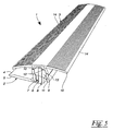
- the inner shell 9 of the rotary joint 10 is displaced vertically upward to the vertical distance of the cover profile 3 from the base profile 2 to enlarge. In this way, relatively thick floor coverings can be covered without having to change the profile rail system 1. Since the inner shell 9 of the rotary joint 10 is almost infinitely variable with respect to the base profile 2, virtually any floor covering thicknesses can be covered in this way. Of course, it is also thought, the displaceability of the inner shell 9 of the rotary joint 10 in the position of the cover profile according to FIG. 1 to use. Through these combinations, all existing in practice flooring thicknesses can be reliably covered.
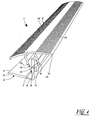
- FIG. 4 shows the profile rail system 1 according to FIG. 3 In a pivoted position of the cover profile 3.
- the swivel joint 10 formed by the webs 6 and the inner shell 9 is used to pivot the cover profile 3 in order to be able to compensate for different floor cover thicknesses safely.
- FIG. 5 the profile rail system 1 according to FIG. 1 in a pivoted position. From this representation it can be seen in particular that the webs 6 should not be too long in the region of the lower part-cylindrical inner contour 12, since otherwise the pivotability of the cover profile 3 would no longer be guaranteed when used for thin floor coverings.
- the covering wings 14 may also be of different lengths, in order to further increase the height compensation between the floor coverings.
Landscapes
- Architecture (AREA)
- Engineering & Computer Science (AREA)
- Civil Engineering (AREA)
- Structural Engineering (AREA)
- Floor Finish (AREA)
- Road Signs Or Road Markings (AREA)
- Housing For Livestock And Birds (AREA)
- Invalid Beds And Related Equipment (AREA)
- Revetment (AREA)
- Machines For Laying And Maintaining Railways (AREA)
- Legs For Furniture In General (AREA)
- Steps, Ramps, And Handrails (AREA)
- Tires In General (AREA)
- Blinds (AREA)
- Curtains And Furnishings For Windows Or Doors (AREA)
- Types And Forms Of Lifts (AREA)
- Chairs For Special Purposes, Such As Reclining Chairs (AREA)
- Escalators And Moving Walkways (AREA)
- Body Structure For Vehicles (AREA)
- Tents Or Canopies (AREA)
- Mutual Connection Of Rods And Tubes (AREA)
Description
- Die Erfindung betrifft ein Profilschienensystem gemäß dem Oberbegriff des Patentanspruchs 1.
- Aus der
EP 1 223 268 A1 ist ein gattungsgemäßes Profilschienensystem zur Überbrückung von Bodenbelagsübergängen bekannt, das von einem Basisprofil und einem Deckprofil gebildet ist. Das Basisprofil weist einen horizontalen Befestigungsschenkel und zwei vertikale Schenkel auf, die innenseitig teilzylinderförmig geformt sind und eine Außenschale eines Drehgelenks bilden. Zwischen diesen beiden vertikalen Schenkeln ist ein Drehkörper gehalten, der eine Innenschale des Drehgelenks bildet und relativ zum Basisprofil verschwenkbar ist. In diesen Drehkörper greift ein Steg des Deckprofils ein, welches im Drehkörper mittels Treibschrauben gehalten ist. Eine Höhenverstellung des Deckprofils ist bei dieser Fußbodenleiste nicht vorgesehen und auch technisch nicht realisierbar. - Aus der
DE 200 15 244 U1 ist ein weiteres Profilschienensystem für Bodenbeläge bekannt. Dieses besteht aus einem Basisprofil mit zwei nach oben gerichteten Stegen, die innenseitig mit einer Sägezahnprofilierung versehen sind. Außerdem weist das Profilschienensystem ein Deckprofil auf, dessen nach unten gerichteter Steg eine in etwa zylindrische Erweiterung aufweist. In diesem erweiterten Bereich ist der Steg außenseitig mit einer korrespondierenden Sägezahnprofilierung versehen. Dieses Profilschienensystem erlaubt eine Höhenverstellung und Verschwenkung des Deckprofils relativ zum Basisprofil. Allerdings werden beide Bewegungsarten durch die gleiche Sägezahnprofilierung ermöglicht, so daß das Deckprofil beim Eindrücken in das Basisprofil nur eine mäßige Führungswirkung erfährt. Dies erschwert die Montage des Deckprofils. - Dokument
DE 20214831 (U ) ist die nächste Stand der Technik, weil es ein Profilschienensystem gemäß der einleitendes Teil des Anspruchs 1 beschreibt. - Der Erfindung liegt die Aufgabe zugrunde, ein Profilschienensystem der eingangs genannten Art zu schaffen, das sich durch eine universellere Einsetzbarkeit und Montageerleichterung auszeichnet.
- Diese Aufgabe wird erfindungsgemäß mit den Merkmalen des Patentanspruchs 1 gelöst.
- Das Profilschienensystem gemäß Anspruch 1 dient zum Überbrücken von Bodenbelagsübergängen, insbesondere mit unterschiedlichen Höhen. Es weist hierzu ein Basisprofil auf, welches in eine Fuge zwischen den aneinander grenzenden Bodenbelägen eingesetzt und darin befestigt wird. Das Basisprofil kann beispielsweise in der Fuge durch Kleben oder Schrauben festgelegt werden. Das Basisprofil weist mindestens einen vertikalen Schenkel auf, an dem eine Schale eines Drehgelenks vorgesehen ist. An diesem Drehgelenk ist ein Deckprofil abgestützt, welches vorzugsweise mit Abdeckflügeln auf den beiden Bodenbelägen aufliegt und die Fuge zwischen den Bodenbelägen überdeckt. Die Außenschale des Drehgelenks wird von zwei nach unten gerichteten Stegen des Deckprofils gebildet, welche teilzylindrische Innenkonturen aufweisen. Zur Erzielung einer Höhenverstellbarkeit des Profilschienensystems sind mindestens zwei dieser teilzylindrischen Innenkonturen an den Stegen übereinander vorgesehen. Damit kann das Deckprofil stufig in erheblichem Maße verstellt werden, um eine Anpassung an unterschiedliche Bodenbelagsdicken zu erzielen. Die teilzylindrischen Innenkonturen der Stege sind passend zur Innenschale des Drehgelenks ausgebildet, so daß sich eine gute Verschwenkbarkeit des Deckprofils gegenüber dem Basisprofil ergibt. Beim Verschwenken des Deckprofils bleibt das Drehgelenk innerhalb der teilzylindrischen Innenkontur der Stege, in die das Drehgelenk eingeklickt oder axial eingeschoben wurde. Dadurch ergibt sich eine leichte Verschwenkbarkeit des Deckprofils relativ zum Drehgelenk, die insbesondere unabhängig von der Höhenverstellbarkeit ist. Damit ist das Deckprofil bei allen Bewegungen sauber geführt und läßt sich somit sehr leicht montieren.
- Um zu verhindern, daß die Stege im Bereich der unteren, teilzylindrischen Innenkonturen die Verschwenkbarkeit des Deckprofils beeinträchtigen, ist es gemäß Anspruch 2 günstig, wenn die unteren Innenkonturen der Stege die Innenschale des Drehgelenks um höchstens je 60° von beiden Seiten umgreifen. Vorzugsweise umgreifen diese Innenkonturen die Innenschale um höchstens 45°. Damit ist auch bei geringer Bodenbelagsdicke eine ausreichende Verschwenkbarkeit des Deckprofils sichergestellt.
- Zur weiteren Verbesserung der Höhenverstellbarkeit des Deckprofils ist es gemäß Anspruch 3 günstig, wenn die Innenschale des Drehgelenks höhenverstellbar am vertikalen Steg des Basisprofils abgestützt ist. Die Innenschale des Drehgelenks bildet dabei ein separates Teil, das sowohl gegenüber dem Basisprofil als auch gegenüber dem Deckprofil verstellbar ist. Durch diese zusätzliche Verstellung ergibt sich ein vergrößerter Höhenverstellbereich, der sich zur stufigen Verstellbarkeit des Deckprofils gegenüber der Innenschale des Drehgelenks addiert. Zusätzlich kann diese Höhenverstellbarkeit stufenlos oder zumindest sehr feinstufig ausgebildet werden, so daß sich eine besonders exakte Anpassung des Deckprofils an die jeweiligen Bodenbelagsdicken ergibt.
- Eine einfache Realisierung der Höhenverstellbarkeit der Innenschale des Drehgelenks ergibt sich gemäß Anspruch 4 durch eine vertikale Nut im Drehgelenk. In diese vertikale Nut greift der vertikale Steg des Basisprofils ein, so daß die Innenschale des Drehgelenks in vertikaler Richtung verschiebbar geführt ist. Diese höhenverstellbare Halterung der Innenschale des Drehgelenks stört die Verschwenkbarkeit des Deckprofils in keiner Weise, wobei sich ein besonders kompakter Aufbau des Profilschienensystems ergibt.
- Zur einfachen Arretierung der Innenschale des Drehgelenks ist es gemäß Anspruch 5 günstig, wenn die Nutwandungen und der vertikale Steg des Basisprofils zueinander passende Zahnprofilierungen aufweisen. Diese Zahnprofilierungen können symmetrisch ausgebildet sein, um gleiche Haltekräfte nach oben und unten zu erzielen. Alternativ können die Zahnprofilierungen auch sägezahnförmig ausgebildet sein, um eine erhöhte Haltekraft des Deckprofils bei entsprechend verringerter Eindrückkraft zu erzielen.
- Schließlich ist es gemäß Anspruch 6 vorteilhaft, die Innenkonturen der Stege und die Außenkonturen der Innenschale des Drehgelenks mit zueinander passenden Zahnprofilierungen zu versehen. Auf diese Weise wird erreicht, daß das Deckprofil zwar gegenüber dem Basisprofil verdrehbar ist, das Deckprofil verbleibt jedoch nach der Montage sicher in der jeweiligen Schwenklage, so daß das Deckprofil besonders leicht zu montieren ist. Außerdem werden ungewollte Verschwenkungen des Deckprofils bei Schwingungen der Bodenbeläge auf diese Weise zuverlässig verhindert.
- Der Erfindungsgegenstand wird beispielhaft anhand der Zeichnung erläutert, ohne den Schutzumfang zu beschränken.
- Es zeigt:
- Figur 1
- eine perspektivische Darstellung eines Profilschienensystems in einer Stellung für geringe Bodenbelagsdicken,
- Figur 2
- das Profilschienensystem gemäß
Figur 1 für mittlere Bodenbelagsdicken, - Figur 3
- das Profilschienensystem gemäß
Figur 2 für große Bodenbelagsdicken, - Figur 4
- das Profilschienensystem gemäß
Figur 3 in verschwenkter Lage des Deckprofils und - Figur 5
- das Profilschienensystem gemäß
Figur 1 in verschwenkter Lage des Deckprofils. - Ein Profilschienensystem 1 gemäß
Figur 1 besteht aus einem Basisprofil 2 und einem Deckprofil 3. Das Basisprofil 2 besitzt einen horizontalen Schenkel 4, der in einer Fuge, beispielsweise durch Kleben oder Schrauben, festgelegt ist. Zu diesem Zweck besitzt der horizontale Schenkel 4 unterseitig eine Profilierung 5, die eine verbesserte Haftung des eingesetzten Klebstoffs bewirkt. Zusätzlich sind im horizontalen Schenkel 4 nicht dargestellte Bohrungen vorgesehen, die von entsprechenden Halteschrauben durchsetzt werden können. - Das Basisprofil 2 weist außerdem einen vertikalen Schenkel 6 auf, der beidseitig mit einer Zahnprofilierung 7 versehen ist. Dieser vertikale Schenkel 6 greift in eine Nut 8 eines Teils 9 ein, welches die Innenschale 9 eines Drehgelenks 10 bildet. Diese Nut 8 ist gleichfalls mit einer passenden Zahnprofilierung 7 versehen, so daß die Innenschale 9 des Drehgelenks 10 vertikal gegenüber dem Basisprofil 2 verschiebbar gehalten ist. Die Zahnprofilierung 7 sorgt dabei für einen festen Halt der Innenschale 9 des Drehgelenks 10 am Basisprofil 2.
- An der Innenschale 9 des Drehgelenks 10 ist das Deckprofil 3 mittels zweier vertikal nach unten gerichteter Stege 11 abgestützt. Diese vertikalen Stege 11 besitzen zwei übereinander gesetzte teilzylindrische Innenkonturen 12, die an die Außenkontur 13 der Innenschale 9 des Drehgelenks 10 angepaßt sind. Auf diese Weise ergibt sich eine Verschwenkbarkeit und Höhenverstellbarkeit des Deckprofils 3 gegenüber dem Basisprofil 2. Das Deckprofil 3 weist zwei Abdeckflügel 14 auf, die mit Lippen 15 an den angrenzenden Bodenbelägen aufliegen. Damit deckt das Deckprofil 3 die zwischen den Bodenbelägen vorgesehene Fuge vollständig ab.
-
Figur 2 zeigt das Profilschienensystem gemäßFigur 1 , wobei gleiche Bezugszeichen gleiche Teile benennen. Im Unterschied zur Ausbildung gemäßFigur 1 ist das Deckprofil 3 gegenüber der Innenschale 9 des Drehgelenks 10 nach oben verschoben, so daß die Innenschale 9 des Drehgelenks 10 von der unteren teilzylindrischen Innenkontur 12 der vertikalen Stege 11 erfaßt wird. Auf diese Weise ergibt sich ein gegenüber der Stellung gemäßFigur 1 erheblich größerer vertikaler Abstand des Deckprofils 3 vom Basisprofil 2, um Bodenbeläge mittlerer Dicke sicher abdekken zu können. - Bei der Stellung gemäß
Figur 3 ist zusätzlich die Innenschale 9 des Drehgelenks 10 vertikal nach oben verschoben, um den vertikalen Abstand des Deckprofils 3 vom Basisprofil 2 zu vergrößern. Auf diese Weise können auch relativ dicke Bodenbeläge abgedeckt werden, ohne das Profilschienensystem 1 wechseln zu müssen. Da die Innenschale 9 des Drehgelenks 10 gegenüber dem Basisprofil 2 nahezu stufenlos verstellbar ist, können praktisch beliebige Bodenbelagsdicken auf diese Weise abgedeckt werden. Selbstverständlich ist auch daran gedacht, die Verschiebbarkeit der Innenschale 9 des Drehgelenks 10 in der Stellung des Deckprofils gemäßFigur 1 zu nutzen. Durch diese Kombinationen können alle in der Praxis vorkommenden Bodenbelagsdicken zuverlässig abgedeckt werden. -
Figur 4 zeigt das Profilschienensystem 1 gemäßFigur 3 in einer verschwenkten Lage des Deckprofils 3. Dabei wird das von den Stegen 6 und der Innenschale 9 gebildete Drehgelenk 10 dazu genutzt, das Deckprofil 3 zu verschwenken, um unterschiedliche Bodenbelagsdicken sicher ausgleichen zu können. - Schließlich zeigt
Figur 5 das Profilschienensystem 1 gemäßFigur 1 in verschwenkter Lage. Aus dieser Darstellung ist insbesondere zu erkennen, daß die Stege 6 im Bereich der unteren teilzylindrischen Innenkontur 12 nicht zu lang ausgebildet sein sollten, da anderenfalls die Verschwenkbarkeit des Deckprofils 3 beim Einsatz für dünne Bodenbeläge nicht mehr gewährleistet wäre. - Alternativ zum dargestellten Ausführungsbeispiel können die Abdeckflügel 14 auch unterschiedlich lang ausgebildet sein, um den Höhenausgleich zwischen den Bodenbelägen weiter zu vergrößern.
-
- 1
- Profilschienensystem
- 2
- Basisprofil
- 3
- Deckprofil
- 4
- horizontaler Steg
- 5
- Profilierung
- 6
- vertikaler Steg
- 7
- Zahnprofilierung
- 8
- Nut
- 9
- Innenschale
- 10
- Drehgelenk
- 11
- vertikaler Steg
- 12
- teilzylindrische Innenkontur
- 13
- Außenkontur
- 14
- Abdeckflügel
- 15
- Lippe
Claims (6)
- Profilschienensystem zur Überbrückung von Bodenbelagsübergängen, -abschlüssen und/oder Treppenkanten, wobei das Profilschienensystem (1) ein Basisprofil (2) aufweist, welches mindestens einen vertikalen Schenkel (6) besitzt, an dem eine Schale (9) eines Drehgelenks (10) vorgesehen ist, welches ein Deckprofil (3) verschwenkbar abstützt, wobei am Deckprofil (3) zwei nach unten gerichtete Stege (11) vorgesehen sind, welche zur Bildung einer Außenschale des Drehgelenks (10) teilzylindrische Innenkonturen (12) aufweisen, die passend zur Innenschale (9) des Drehgelenks (10) ausgebildet sind, dadurch gekennzeichnet, daß zur Erzielung einer stufigen Verstellbarkeit des Deckprofils (3) mindestens zwei der teilzylindrischen Innenkonturen (12) übereinander liegend vorgesehen sind, wobei das Drehgelenk (10) wahlweise in jeweils eine der teilzylindrischen Innenkonturen (12) einklickbar und/oder axial einschiebbar und innerhalb der teilzylindrischen Innenkontur (12) verschwenkbar ist.
- Profilschienensystem nach Anspruch 1, dadurch gekennzeichnet, daß zumindest die unteren teilzylindrischen Innenkonturen der Stege (11) die Innenschale (9) des Drehgelenks (10) um höchstens je 60° von beiden Seiten umgreifen.
- Profilschienensystem nach Anspruch 1 oder 2, dadurch gekennzeichnet, daß die Innenschale (9) des Drehgelenks (10) höhenverstellbar am vertikalen Steg (6) des Basisprofils (2) abgestützt ist.
- Profilschienensystem nach Anspruch 3, dadurch gekennzeichnet, daß die Innenschale (9) des Drehgelenks (10) eine vertikale Nut (8) aufweist, in die der vertikale Steg (6) des Basisprofils (2) eingreift.
- Profilschienensystem nach Anspruch 4, dadurch gekennzeichnet, daß in den Wandungen der vertikalen Nut (8) der Innenschale (9) des Drehgelenks (10) und am vertikalen Steg (6) des Basisprofils (2) zueinander passende Zahnprofilierungen (7) vorgesehen sind.
- Profilschienensystem nach mindestens einem der Ansprüche 1 bis 5, dadurch gekennzeichnet, daß die Innenkonturen (12) der Stege (11) und die Außenkontur der Innenschale (9) des Drehgelenks (10) zueinander passende Zahnprofilierungen aufweisen.
Priority Applications (2)
| Application Number | Priority Date | Filing Date | Title |
|---|---|---|---|
| PL05000573T PL1555360T3 (pl) | 2004-01-16 | 2005-01-13 | System szyn profilowych do pokrywania przejść wykładzin podłogowych |
| SI200530626T SI1555360T1 (sl) | 2004-01-16 | 2005-01-13 | Sistem profilnih letev za premoščanje prehodov med talnimi oblogami |
Applications Claiming Priority (2)
| Application Number | Priority Date | Filing Date | Title |
|---|---|---|---|
| DE202004000706U | 2004-01-16 | ||
| DE202004000706U DE202004000706U1 (de) | 2004-01-16 | 2004-01-16 | Profilschienensystem zur Überprüfung von Bodenbelagsübergängen |
Publications (3)
| Publication Number | Publication Date |
|---|---|
| EP1555360A2 EP1555360A2 (de) | 2005-07-20 |
| EP1555360A3 EP1555360A3 (de) | 2006-05-24 |
| EP1555360B1 true EP1555360B1 (de) | 2008-12-17 |
Family
ID=32319269
Family Applications (1)
| Application Number | Title | Priority Date | Filing Date |
|---|---|---|---|
| EP05000573A Expired - Lifetime EP1555360B1 (de) | 2004-01-16 | 2005-01-13 | Profilschienensystem zur Überbrückung von Bodenbelagsübergängen |
Country Status (17)
| Country | Link |
|---|---|
| US (1) | US7392627B2 (de) |
| EP (1) | EP1555360B1 (de) |
| CN (1) | CN100374671C (de) |
| AT (1) | ATE417973T1 (de) |
| AU (1) | AU2005200178B2 (de) |
| BR (1) | BRPI0405955B1 (de) |
| CA (1) | CA2492401C (de) |
| DE (2) | DE202004000706U1 (de) |
| DK (1) | DK1555360T3 (de) |
| EA (1) | EA006517B1 (de) |
| ES (1) | ES2319540T3 (de) |
| MX (1) | MXPA05000582A (de) |
| NZ (1) | NZ537679A (de) |
| PL (1) | PL1555360T3 (de) |
| PT (1) | PT1555360E (de) |
| RS (1) | RS50845B (de) |
| SI (1) | SI1555360T1 (de) |
Families Citing this family (24)
| Publication number | Priority date | Publication date | Assignee | Title |
|---|---|---|---|---|
| DE202004018094U1 (de) * | 2004-11-22 | 2005-02-03 | Karl Pedross Ag | Profilschienensystem zum Abdecken von Fugen |
| ITPD20050049A1 (it) * | 2005-02-24 | 2006-08-25 | Profilpas Snc | Profili per la posa dei pavimenti in ceramica, legno, pavimenti laminati, moquette, ecc. |
| DE202005004624U1 (de) | 2005-03-19 | 2005-07-21 | Herm. Friedr. Künne Gmbh & Co. | Profilschienensystem |
| US20070028550A1 (en) * | 2005-07-20 | 2007-02-08 | Clapper Edward O | Rafter platform |
| AT503244A3 (de) * | 2005-10-24 | 2009-12-15 | Neuhofer Franz Jun | Vorrichtung zum stirnseitigen abschliessen eines bodenbelages |
| DE202005020074U1 (de) * | 2005-12-21 | 2006-04-20 | Herm. Friedr. Künne Gmbh & Co. | Profilschienensystem |
| DE202006000428U1 (de) * | 2006-01-11 | 2006-03-30 | Fiedler, Karl-Heinz | Fußbodenleiste |
| GB2449482A (en) * | 2007-05-24 | 2008-11-26 | Western Cork Ltd | Threshold trim strip |
| US7600352B2 (en) * | 2007-10-24 | 2009-10-13 | Schulze Todd M | Slab saver form attachment device |
| DE202009007156U1 (de) * | 2009-05-18 | 2009-08-20 | Sondermann, Thomas | Profilschienensystem zum Abdecken mindestens eines Belagrandes |
| DE102011000524A1 (de) * | 2011-02-04 | 2012-08-09 | Fleischmann & Kollegen GmbH | Fußbodenleiste zum Abdecken einer Fuge zwischen zwei aneinandergrenzende Bodenbeläge |
| US9366040B2 (en) * | 2011-04-11 | 2016-06-14 | Easytrim Reveals Inc. | Wall panel trim reveal system and method |
| CN102287043B (zh) * | 2011-06-29 | 2013-03-13 | 常熟市古里镇白茆联动建筑变形缝装置厂 | 一种石材分隔条 |
| CN103711267A (zh) * | 2012-10-08 | 2014-04-09 | 薛童 | 楼梯安全气囊托盘 |
| CN103422649B (zh) * | 2013-08-15 | 2017-08-08 | 浙江亚厦装饰股份有限公司 | 一种石材地板与地毯的拼接结构 |
| US20150204084A1 (en) * | 2014-01-17 | 2015-07-23 | Fukuvi Usa, Inc. | Height-adjustable caps for concrete shuttering formwork |
| US9945483B2 (en) * | 2014-05-05 | 2018-04-17 | Lockheed Martin Corporation | System and apparatus for aerodynamically sealing surfaces |
| CN104196213B (zh) * | 2014-07-14 | 2016-08-24 | 苏州金螳螂幕墙有限公司 | 一种装饰线万维转动连接件 |
| USD823487S1 (en) * | 2016-01-05 | 2018-07-17 | Ryan Peterson | Rubber cushion with interlocking tabs |
| US10202777B1 (en) * | 2017-08-08 | 2019-02-12 | Dennis Leavey | Securement devices for securing molding to a surface, and methods of securing molding to a surface |
| FR3076563B1 (fr) * | 2018-01-09 | 2020-06-19 | Fixat | Accessoire de finition deformable adapte pour former un raccord entre deux surfaces |
| CA185784S (en) * | 2019-01-18 | 2020-06-30 | Brand Shared Services Llc | Forming panel insert |
| USD924438S1 (en) * | 2019-05-08 | 2021-07-06 | Mark Zabala | Cove system |
| USD1109293S1 (en) * | 2023-03-28 | 2026-01-13 | Ebbe America Lc | Shower curb cap |
Family Cites Families (26)
| Publication number | Priority date | Publication date | Assignee | Title |
|---|---|---|---|---|
| US3254361A (en) * | 1964-11-16 | 1966-06-07 | William L Bonnell Company Inc | Carpet-edge binding means |
| US3473278A (en) * | 1968-02-01 | 1969-10-21 | Gossen Corp | Wall trim assemblies |
| US3696461A (en) * | 1969-07-28 | 1972-10-10 | Robert G Kelly | Carpet installation system for use in an aircraft |
| US3688340A (en) * | 1970-12-21 | 1972-09-05 | Aircheck Inc | Roller assembly for sliding panels |
| US4067155A (en) * | 1975-08-28 | 1978-01-10 | Grefco, Inc. | Sealing system |
| FR2367886A1 (fr) * | 1976-10-15 | 1978-05-12 | Dinac Sa | Profiles de jonction de revetements |
| US4189880A (en) * | 1978-06-16 | 1980-02-26 | Gene Ballin | Combination mounting frame and film for a window |
| US4858405A (en) * | 1987-07-10 | 1989-08-22 | Christie Dawson A | Building system for windows, enclosures, buildings and the like |
| CH676275A5 (de) * | 1987-11-12 | 1990-12-28 | Daetwyler Ag | |
| DE9412987U1 (de) * | 1994-08-11 | 1994-10-27 | Seiß, Helmut, 85080 Gaimersheim | Profilschienensystem zum Überbrücken von Fugen oder Rändern bei Belägen |
| US20030084634A1 (en) * | 2001-11-08 | 2003-05-08 | Oliver Stanchfield | Transition molding |
| DE4439963B4 (de) * | 1994-11-09 | 2005-10-20 | Alfer Aluminium Gmbh | Fugenabdeckvorrichtung |
| US5939670A (en) * | 1997-11-06 | 1999-08-17 | Scientific Technologies Incorporated | Trim structure for safetymat |
| US6199328B1 (en) * | 1998-12-11 | 2001-03-13 | Owens Corning Fiberglas Technology, Inc. | Clamp assembly for attaching panels to substrate |
| DE29822236U1 (de) * | 1998-12-14 | 1999-03-18 | Schlüter-Systems GmbH, 58640 Iserlohn | Vorrichtung zur Ausbildung des Übergangs zwischen zwei aneinandergrenzenden Bodenabschnitten unterschiedlicher Höhe |
| DE29916138U1 (de) * | 1999-09-14 | 2000-01-13 | Xaver Grünwald GmbH, 86633 Neuburg | Leistenanordnung zum Abdecken oder Überbrücken von Fugen, insbesondere für Fußböden |
| SE517353C2 (sv) * | 1999-12-13 | 2002-05-28 | Perstorp Flooring Ab | Övergångslist vid golv avsedd att placeras vid en golvenhets ände eller mellan två golvenheter |
| AT4086U1 (de) * | 1999-12-22 | 2001-01-25 | Neuhofer Franz Jun | Abdeckvorrichtung für bodenbelagsfugen od. dgl. |
| DE50012775D1 (de) * | 2000-09-01 | 2006-06-22 | Carl Prinz Gmbh & Co | Profilschienensystem für Bodenbeläge |
| DE20015244U1 (de) * | 2000-09-01 | 2001-02-22 | Carl Prinz GmbH & Co. Metallwarenfabrik, 47574 Goch | Profilschienensystem für Bodenbeläge |
| DE20015224U1 (de) * | 2000-09-04 | 2000-12-14 | Insta Elektro GmbH & Co KG, 58511 Lüdenscheid | Universelle elektrische/elektronische Anschlussanordnung |
| FR2815983B1 (fr) * | 2000-11-02 | 2003-06-06 | Michel Grosjean | Couvre-joint |
| JP2002168333A (ja) | 2000-11-28 | 2002-06-14 | Fuji Heavy Ind Ltd | 自動車のヒルホールド制御装置 |
| DE20100413U1 (de) * | 2001-01-11 | 2002-03-21 | PROLINE Profil System GmbH, 56154 Boppard | Fußbodenleiste |
| DE20214831U1 (de) * | 2002-09-24 | 2003-02-27 | Mako Pinsel GmbH, 91596 Burk | Profilschienensystem |
| EP1403444A1 (de) * | 2002-09-24 | 2004-03-31 | Manfred Kochler | Profilschienensystem |
-
2004
- 2004-01-16 DE DE202004000706U patent/DE202004000706U1/de not_active Expired - Lifetime
- 2004-12-29 BR BRPI0405955-7B1A patent/BRPI0405955B1/pt not_active IP Right Cessation
-
2005
- 2005-01-13 PT PT05000573T patent/PT1555360E/pt unknown
- 2005-01-13 CA CA002492401A patent/CA2492401C/en not_active Expired - Fee Related
- 2005-01-13 DE DE502005006243T patent/DE502005006243D1/de not_active Expired - Lifetime
- 2005-01-13 RS RSP-2009/0111A patent/RS50845B/sr unknown
- 2005-01-13 SI SI200530626T patent/SI1555360T1/sl unknown
- 2005-01-13 ES ES05000573T patent/ES2319540T3/es not_active Expired - Lifetime
- 2005-01-13 DK DK05000573T patent/DK1555360T3/da active
- 2005-01-13 AT AT05000573T patent/ATE417973T1/de active
- 2005-01-13 PL PL05000573T patent/PL1555360T3/pl unknown
- 2005-01-13 MX MXPA05000582A patent/MXPA05000582A/es active IP Right Grant
- 2005-01-13 EP EP05000573A patent/EP1555360B1/de not_active Expired - Lifetime
- 2005-01-14 EA EA200500026A patent/EA006517B1/ru not_active IP Right Cessation
- 2005-01-14 CN CNB2005100045164A patent/CN100374671C/zh not_active Expired - Fee Related
- 2005-01-14 NZ NZ537679A patent/NZ537679A/en not_active IP Right Cessation
- 2005-01-14 US US11/035,825 patent/US7392627B2/en not_active Expired - Lifetime
- 2005-01-14 AU AU2005200178A patent/AU2005200178B2/en not_active Ceased
Also Published As
| Publication number | Publication date |
|---|---|
| BRPI0405955A (pt) | 2005-09-20 |
| DK1555360T3 (da) | 2009-04-14 |
| DE202004000706U1 (de) | 2004-05-13 |
| SI1555360T1 (sl) | 2009-06-30 |
| RS50845B (sr) | 2010-08-31 |
| DE502005006243D1 (de) | 2009-01-29 |
| US7392627B2 (en) | 2008-07-01 |
| ES2319540T3 (es) | 2009-05-08 |
| ATE417973T1 (de) | 2009-01-15 |
| EP1555360A2 (de) | 2005-07-20 |
| PT1555360E (pt) | 2009-03-16 |
| CN1641135A (zh) | 2005-07-20 |
| AU2005200178B2 (en) | 2007-02-15 |
| BRPI0405955B1 (pt) | 2014-08-05 |
| EA200500026A1 (ru) | 2005-08-25 |
| CA2492401A1 (en) | 2005-07-16 |
| US20050188628A1 (en) | 2005-09-01 |
| EA006517B1 (ru) | 2005-12-29 |
| AU2005200178A1 (en) | 2005-08-04 |
| MXPA05000582A (es) | 2005-08-29 |
| CA2492401C (en) | 2009-06-16 |
| PL1555360T3 (pl) | 2009-05-29 |
| CN100374671C (zh) | 2008-03-12 |
| EP1555360A3 (de) | 2006-05-24 |
| NZ537679A (en) | 2007-01-26 |
Similar Documents
| Publication | Publication Date | Title |
|---|---|---|
| EP1555360A2 (de) | Profilschienensystem zur Überbrückung von Bodenbelagsübergängen | |
| AT509796B1 (de) | Hohlprofil | |
| EP2050898A1 (de) | Fußbodenprofilanordnung mit Gelenk | |
| EP3241974B1 (de) | Anordnung für eine dichtung, insbesondere für eine auflaufdichtung oder für eine sich selbsttätig absenkende bodendichtung für türen | |
| EP2255058B1 (de) | Aufsatz-Rollladenkasten sowie Profilsystem mit einem solchen Aufsatz-Rollladenkasten | |
| DE102008006917B4 (de) | Vorrichtung zur Lageverstellung eines Kabelkanals oder dergleichen | |
| CH460296A (de) | Kantenabdeckung für Flachdächer, Schrägdächer, Terrassenböden und dergleichen | |
| DE2535255A1 (de) | Dachdurchfuehrung | |
| DE202004009557U1 (de) | System zur Aufhängung von Rohren, Leitungen o.dgl. an einer Decke | |
| EP1439269B1 (de) | Verbinder für die Befestigung von Montageprofilen der Sanitärtechnik sowie Traggestell mit einem solchen Verbinder | |
| EP0761153B1 (de) | Vorrichtung für den Einbau einer Bade- oder Duschwanne | |
| AT402834B (de) | Verstellbarer firstlattenhalter für eine dachstuhlkonstruktion | |
| DE10136348C1 (de) | Halterung für eine ausrichtbare Befestigung der Stützen eines Balkongeländers | |
| DE202014002034U1 (de) | Stützhalter zur Wandmontage einer Simsplatte | |
| DE202007003287U1 (de) | Vorrichtung zum Befestigen eines Geländers | |
| DE2817768B2 (de) | Geländer oder dergleichen | |
| DE2916496A1 (de) | Gelenkarmmarkise | |
| DE8420711U1 (de) | Befestigungsvorrichtung für eine Dekorplatte an der Gerätetür eines Einbaukühlschrankes | |
| EP0617191B1 (de) | Führungsschienenanordnung für eine Wintergartenmarkise o. dgl. | |
| EP2959812B1 (de) | Anordnung zum verbinden zweier profilschienen | |
| EP3569794B1 (de) | Profilschienensystem | |
| EP3412844B1 (de) | Dachrinnen-befestigungsanordnung, dachanordnung und verfahren zur montage einer dachrinne | |
| EP0197354B1 (de) | Jalousie | |
| DE29902096U1 (de) | Duschabtrennung | |
| EP0237634B1 (de) | Vorrichtung zum Befestigen von hinterlüfteten Fassadenplatten an einem Bauwerk |
Legal Events
| Date | Code | Title | Description |
|---|---|---|---|
| PUAI | Public reference made under article 153(3) epc to a published international application that has entered the european phase |
Free format text: ORIGINAL CODE: 0009012 |
|
| AK | Designated contracting states |
Kind code of ref document: A2 Designated state(s): AT BE BG CH CY CZ DE DK EE ES FI FR GB GR HU IE IS IT LI LT LU MC NL PL PT RO SE SI SK TR |
|
| AX | Request for extension of the european patent |
Extension state: AL BA HR LV MK YU |
|
| PUAL | Search report despatched |
Free format text: ORIGINAL CODE: 0009013 |
|
| AK | Designated contracting states |
Kind code of ref document: A3 Designated state(s): AT BE BG CH CY CZ DE DK EE ES FI FR GB GR HU IE IS IT LI LT LU MC NL PL PT RO SE SI SK TR |
|
| AX | Request for extension of the european patent |
Extension state: AL BA HR LV MK YU |
|
| 17P | Request for examination filed |
Effective date: 20060614 |
|
| AKX | Designation fees paid |
Designated state(s): AT BE BG CH CY CZ DE DK EE ES FI FR GB GR HU IE IS IT LI LT LU MC NL PL PT RO SE SI SK TR |
|
| AXX | Extension fees paid |
Extension state: YU Payment date: 20060614 Extension state: LV Payment date: 20060614 Extension state: AL Payment date: 20060614 |
|
| GRAP | Despatch of communication of intention to grant a patent |
Free format text: ORIGINAL CODE: EPIDOSNIGR1 |
|
| GRAS | Grant fee paid |
Free format text: ORIGINAL CODE: EPIDOSNIGR3 |
|
| GRAA | (expected) grant |
Free format text: ORIGINAL CODE: 0009210 |
|
| AK | Designated contracting states |
Kind code of ref document: B1 Designated state(s): AT BE BG CH CY CZ DE DK EE ES FI FR GB GR HU IE IS IT LI LT LU MC NL PL PT RO SE SI SK TR |
|
| AX | Request for extension of the european patent |
Extension state: AL LV YU |
|
| REG | Reference to a national code |
Ref country code: GB Ref legal event code: FG4D Free format text: NOT ENGLISH |
|
| REG | Reference to a national code |
Ref country code: CH Ref legal event code: EP |
|
| REG | Reference to a national code |
Ref country code: IE Ref legal event code: FG4D Free format text: LANGUAGE OF EP DOCUMENT: GERMAN |
|
| REF | Corresponds to: |
Ref document number: 502005006243 Country of ref document: DE Date of ref document: 20090129 Kind code of ref document: P |
|
| REG | Reference to a national code |
Ref country code: RO Ref legal event code: EPE |
|
| REG | Reference to a national code |
Ref country code: PT Ref legal event code: SC4A Free format text: AVAILABILITY OF NATIONAL TRANSLATION Effective date: 20090305 |
|
| REG | Reference to a national code |
Ref country code: SE Ref legal event code: TRGR |
|
| REG | Reference to a national code |
Ref country code: GR Ref legal event code: EP Ref document number: 20090400785 Country of ref document: GR |
|
| REG | Reference to a national code |
Ref country code: DK Ref legal event code: T3 |
|
| REG | Reference to a national code |
Ref country code: ES Ref legal event code: FG2A Ref document number: 2319540 Country of ref document: ES Kind code of ref document: T3 |
|
| REG | Reference to a national code |
Ref country code: PL Ref legal event code: T3 |
|
| PG25 | Lapsed in a contracting state [announced via postgrant information from national office to epo] |
Ref country code: MC Free format text: LAPSE BECAUSE OF NON-PAYMENT OF DUE FEES Effective date: 20090131 Ref country code: IS Free format text: LAPSE BECAUSE OF FAILURE TO SUBMIT A TRANSLATION OF THE DESCRIPTION OR TO PAY THE FEE WITHIN THE PRESCRIBED TIME-LIMIT Effective date: 20090417 |
|
| REG | Reference to a national code |
Ref country code: HU Ref legal event code: AG4A Ref document number: E005498 Country of ref document: HU |
|
| PLBE | No opposition filed within time limit |
Free format text: ORIGINAL CODE: 0009261 |
|
| STAA | Information on the status of an ep patent application or granted ep patent |
Free format text: STATUS: NO OPPOSITION FILED WITHIN TIME LIMIT |
|
| 26N | No opposition filed |
Effective date: 20090918 |
|
| PG25 | Lapsed in a contracting state [announced via postgrant information from national office to epo] |
Ref country code: CY Free format text: LAPSE BECAUSE OF FAILURE TO SUBMIT A TRANSLATION OF THE DESCRIPTION OR TO PAY THE FEE WITHIN THE PRESCRIBED TIME-LIMIT Effective date: 20081217 |
|
| REG | Reference to a national code |
Ref country code: FR Ref legal event code: PLFP Year of fee payment: 12 |
|
| PGFP | Annual fee paid to national office [announced via postgrant information from national office to epo] |
Ref country code: LT Payment date: 20151223 Year of fee payment: 12 |
|
| PGFP | Annual fee paid to national office [announced via postgrant information from national office to epo] |
Ref country code: PL Payment date: 20151221 Year of fee payment: 12 Ref country code: RO Payment date: 20151221 Year of fee payment: 12 Ref country code: PT Payment date: 20151221 Year of fee payment: 12 Ref country code: CZ Payment date: 20151223 Year of fee payment: 12 Ref country code: SK Payment date: 20151222 Year of fee payment: 12 |
|
| PGFP | Annual fee paid to national office [announced via postgrant information from national office to epo] |
Ref country code: LU Payment date: 20160122 Year of fee payment: 12 |
|
| PGFP | Annual fee paid to national office [announced via postgrant information from national office to epo] |
Ref country code: TR Payment date: 20160111 Year of fee payment: 12 Ref country code: ES Payment date: 20160111 Year of fee payment: 12 Ref country code: BG Payment date: 20160201 Year of fee payment: 12 Ref country code: IE Payment date: 20160121 Year of fee payment: 12 Ref country code: EE Payment date: 20160126 Year of fee payment: 12 Ref country code: DK Payment date: 20160127 Year of fee payment: 12 Ref country code: IT Payment date: 20160129 Year of fee payment: 12 |
|
| PGFP | Annual fee paid to national office [announced via postgrant information from national office to epo] |
Ref country code: FI Payment date: 20160125 Year of fee payment: 12 Ref country code: HU Payment date: 20160111 Year of fee payment: 12 Ref country code: GR Payment date: 20160127 Year of fee payment: 12 Ref country code: BE Payment date: 20160121 Year of fee payment: 12 Ref country code: SI Payment date: 20151223 Year of fee payment: 12 Ref country code: GB Payment date: 20160127 Year of fee payment: 12 Ref country code: SE Payment date: 20160127 Year of fee payment: 12 Ref country code: FR Payment date: 20160128 Year of fee payment: 12 |
|
| PG25 | Lapsed in a contracting state [announced via postgrant information from national office to epo] |
Ref country code: BE Free format text: LAPSE BECAUSE OF NON-PAYMENT OF DUE FEES Effective date: 20170131 |
|
| REG | Reference to a national code |
Ref country code: LT Ref legal event code: MM4D Effective date: 20170113 |
|
| REG | Reference to a national code |
Ref country code: EE Ref legal event code: MM4A Ref document number: E003184 Country of ref document: EE Effective date: 20170131 |
|
| REG | Reference to a national code |
Ref country code: DK Ref legal event code: EBP Effective date: 20170131 |
|
| GBPC | Gb: european patent ceased through non-payment of renewal fee |
Effective date: 20170113 |
|
| REG | Reference to a national code |
Ref country code: SK Ref legal event code: MM4A Ref document number: E 5177 Country of ref document: SK Effective date: 20170113 |
|
| REG | Reference to a national code |
Ref country code: FR Ref legal event code: ST Effective date: 20170929 |
|
| REG | Reference to a national code |
Ref country code: SI Ref legal event code: KO00 Effective date: 20170912 |
|
| PG25 | Lapsed in a contracting state [announced via postgrant information from national office to epo] |
Ref country code: FI Free format text: LAPSE BECAUSE OF NON-PAYMENT OF DUE FEES Effective date: 20170113 Ref country code: EE Free format text: LAPSE BECAUSE OF NON-PAYMENT OF DUE FEES Effective date: 20170131 Ref country code: FR Free format text: LAPSE BECAUSE OF NON-PAYMENT OF DUE FEES Effective date: 20170131 Ref country code: SK Free format text: LAPSE BECAUSE OF NON-PAYMENT OF DUE FEES Effective date: 20170113 Ref country code: LT Free format text: LAPSE BECAUSE OF NON-PAYMENT OF DUE FEES Effective date: 20170113 Ref country code: RO Free format text: LAPSE BECAUSE OF NON-PAYMENT OF DUE FEES Effective date: 20170113 Ref country code: CZ Free format text: LAPSE BECAUSE OF NON-PAYMENT OF DUE FEES Effective date: 20170113 Ref country code: GR Free format text: LAPSE BECAUSE OF NON-PAYMENT OF DUE FEES Effective date: 20170811 |
|
| REG | Reference to a national code |
Ref country code: IE Ref legal event code: MM4A |
|
| PG25 | Lapsed in a contracting state [announced via postgrant information from national office to epo] |
Ref country code: LU Free format text: LAPSE BECAUSE OF NON-PAYMENT OF DUE FEES Effective date: 20170113 Ref country code: SI Free format text: LAPSE BECAUSE OF NON-PAYMENT OF DUE FEES Effective date: 20170114 Ref country code: SE Free format text: LAPSE BECAUSE OF NON-PAYMENT OF DUE FEES Effective date: 20170114 Ref country code: PT Free format text: LAPSE BECAUSE OF NON-PAYMENT OF DUE FEES Effective date: 20170713 Ref country code: HU Free format text: LAPSE BECAUSE OF NON-PAYMENT OF DUE FEES Effective date: 20170114 Ref country code: GB Free format text: LAPSE BECAUSE OF NON-PAYMENT OF DUE FEES Effective date: 20170113 |
|
| PG25 | Lapsed in a contracting state [announced via postgrant information from national office to epo] |
Ref country code: DK Free format text: LAPSE BECAUSE OF NON-PAYMENT OF DUE FEES Effective date: 20170131 |
|
| REG | Reference to a national code |
Ref country code: BE Ref legal event code: MM Effective date: 20170131 |
|
| PG25 | Lapsed in a contracting state [announced via postgrant information from national office to epo] |
Ref country code: IT Free format text: LAPSE BECAUSE OF NON-PAYMENT OF DUE FEES Effective date: 20170113 Ref country code: IE Free format text: LAPSE BECAUSE OF NON-PAYMENT OF DUE FEES Effective date: 20170113 |
|
| PG25 | Lapsed in a contracting state [announced via postgrant information from national office to epo] |
Ref country code: ES Free format text: LAPSE BECAUSE OF NON-PAYMENT OF DUE FEES Effective date: 20170114 |
|
| PG25 | Lapsed in a contracting state [announced via postgrant information from national office to epo] |
Ref country code: PL Free format text: LAPSE BECAUSE OF NON-PAYMENT OF DUE FEES Effective date: 20170113 |
|
| REG | Reference to a national code |
Ref country code: ES Ref legal event code: FD2A Effective date: 20181116 |
|
| PG25 | Lapsed in a contracting state [announced via postgrant information from national office to epo] |
Ref country code: BG Free format text: LAPSE BECAUSE OF NON-PAYMENT OF DUE FEES Effective date: 20170808 |
|
| REG | Reference to a national code |
Ref country code: DE Ref legal event code: R082 Ref document number: 502005006243 Country of ref document: DE Ref country code: DE Ref legal event code: R082 Ref document number: 502005006243 Country of ref document: DE Representative=s name: PATENTANWAELTE STAEGER & SPERLING PARTNERSCHAF, DE |
|
| REG | Reference to a national code |
Ref country code: DE Ref legal event code: R082 Ref document number: 502005006243 Country of ref document: DE Representative=s name: PATENTANWAELTE STAEGER & SPERLING PARTNERSCHAF, DE |
|
| PG25 | Lapsed in a contracting state [announced via postgrant information from national office to epo] |
Ref country code: TR Free format text: LAPSE BECAUSE OF NON-PAYMENT OF DUE FEES Effective date: 20170113 |
|
| PGFP | Annual fee paid to national office [announced via postgrant information from national office to epo] |
Ref country code: CH Payment date: 20230111 Year of fee payment: 19 Ref country code: AT Payment date: 20230120 Year of fee payment: 19 |
|
| PGFP | Annual fee paid to national office [announced via postgrant information from national office to epo] |
Ref country code: DE Payment date: 20230327 Year of fee payment: 19 |
|
| PGFP | Annual fee paid to national office [announced via postgrant information from national office to epo] |
Ref country code: NL Payment date: 20230119 Year of fee payment: 19 |
|
| REG | Reference to a national code |
Ref country code: DE Ref legal event code: R119 Ref document number: 502005006243 Country of ref document: DE |
|
| REG | Reference to a national code |
Ref country code: CH Ref legal event code: PL |
|
| REG | Reference to a national code |
Ref country code: NL Ref legal event code: MM Effective date: 20240201 |
|
| REG | Reference to a national code |
Ref country code: AT Ref legal event code: MM01 Ref document number: 417973 Country of ref document: AT Kind code of ref document: T Effective date: 20240113 |
|
| PG25 | Lapsed in a contracting state [announced via postgrant information from national office to epo] |
Ref country code: DE Free format text: LAPSE BECAUSE OF NON-PAYMENT OF DUE FEES Effective date: 20240801 |
|
| PG25 | Lapsed in a contracting state [announced via postgrant information from national office to epo] |
Ref country code: NL Free format text: LAPSE BECAUSE OF NON-PAYMENT OF DUE FEES Effective date: 20240201 |
|
| PG25 | Lapsed in a contracting state [announced via postgrant information from national office to epo] |
Ref country code: CH Free format text: LAPSE BECAUSE OF NON-PAYMENT OF DUE FEES Effective date: 20240131 |
|
| PG25 | Lapsed in a contracting state [announced via postgrant information from national office to epo] |
Ref country code: AT Free format text: LAPSE BECAUSE OF NON-PAYMENT OF DUE FEES Effective date: 20240113 |
|
| PG25 | Lapsed in a contracting state [announced via postgrant information from national office to epo] |
Ref country code: NL Free format text: LAPSE BECAUSE OF NON-PAYMENT OF DUE FEES Effective date: 20240201 Ref country code: DE Free format text: LAPSE BECAUSE OF NON-PAYMENT OF DUE FEES Effective date: 20240801 Ref country code: CH Free format text: LAPSE BECAUSE OF NON-PAYMENT OF DUE FEES Effective date: 20240131 Ref country code: AT Free format text: LAPSE BECAUSE OF NON-PAYMENT OF DUE FEES Effective date: 20240113 |