EP1550774B1 - Steuersystem eines Stempels eines Radladers - Google Patents
Steuersystem eines Stempels eines Radladers Download PDFInfo
- Publication number
- EP1550774B1 EP1550774B1 EP04030864A EP04030864A EP1550774B1 EP 1550774 B1 EP1550774 B1 EP 1550774B1 EP 04030864 A EP04030864 A EP 04030864A EP 04030864 A EP04030864 A EP 04030864A EP 1550774 B1 EP1550774 B1 EP 1550774B1
- Authority
- EP
- European Patent Office
- Prior art keywords
- ram cylinder
- ram
- joystick
- cylinder control
- control valve
- Prior art date
- Legal status (The legal status is an assumption and is not a legal conclusion. Google has not performed a legal analysis and makes no representation as to the accuracy of the status listed.)
- Ceased
Links
- 239000010720 hydraulic oil Substances 0.000 claims description 35
- 230000007935 neutral effect Effects 0.000 claims description 12
- 239000012530 fluid Substances 0.000 claims description 6
- 238000010586 diagram Methods 0.000 description 5
- 238000001514 detection method Methods 0.000 description 2
- 230000005540 biological transmission Effects 0.000 description 1
- 230000000903 blocking effect Effects 0.000 description 1
- 238000010276 construction Methods 0.000 description 1
- 238000000034 method Methods 0.000 description 1
- 239000003921 oil Substances 0.000 description 1
Images


Classifications
-
- E—FIXED CONSTRUCTIONS
- E02—HYDRAULIC ENGINEERING; FOUNDATIONS; SOIL SHIFTING
- E02F—DREDGING; SOIL-SHIFTING
- E02F9/00—Component parts of dredgers or soil-shifting machines, not restricted to one of the kinds covered by groups E02F3/00 - E02F7/00
- E02F9/20—Drives; Control devices
- E02F9/22—Hydraulic or pneumatic drives
- E02F9/2203—Arrangements for controlling the attitude of actuators, e.g. speed, floating function
- E02F9/2207—Arrangements for controlling the attitude of actuators, e.g. speed, floating function for reducing or compensating oscillations
-
- E—FIXED CONSTRUCTIONS
- E02—HYDRAULIC ENGINEERING; FOUNDATIONS; SOIL SHIFTING
- E02F—DREDGING; SOIL-SHIFTING
- E02F9/00—Component parts of dredgers or soil-shifting machines, not restricted to one of the kinds covered by groups E02F3/00 - E02F7/00
- E02F9/20—Drives; Control devices
-
- E—FIXED CONSTRUCTIONS
- E02—HYDRAULIC ENGINEERING; FOUNDATIONS; SOIL SHIFTING
- E02F—DREDGING; SOIL-SHIFTING
- E02F9/00—Component parts of dredgers or soil-shifting machines, not restricted to one of the kinds covered by groups E02F3/00 - E02F7/00
- E02F9/20—Drives; Control devices
- E02F9/22—Hydraulic or pneumatic drives
- E02F9/2217—Hydraulic or pneumatic drives with energy recovery arrangements, e.g. using accumulators, flywheels
-
- E—FIXED CONSTRUCTIONS
- E02—HYDRAULIC ENGINEERING; FOUNDATIONS; SOIL SHIFTING
- E02F—DREDGING; SOIL-SHIFTING
- E02F9/00—Component parts of dredgers or soil-shifting machines, not restricted to one of the kinds covered by groups E02F3/00 - E02F7/00
- E02F9/20—Drives; Control devices
- E02F9/22—Hydraulic or pneumatic drives
- E02F9/226—Safety arrangements, e.g. hydraulic driven fans, preventing cavitation, leakage, overheating
-
- E—FIXED CONSTRUCTIONS
- E02—HYDRAULIC ENGINEERING; FOUNDATIONS; SOIL SHIFTING
- E02F—DREDGING; SOIL-SHIFTING
- E02F9/00—Component parts of dredgers or soil-shifting machines, not restricted to one of the kinds covered by groups E02F3/00 - E02F7/00
- E02F9/20—Drives; Control devices
- E02F9/22—Hydraulic or pneumatic drives
- E02F9/2278—Hydraulic circuits
- E02F9/2292—Systems with two or more pumps
-
- E—FIXED CONSTRUCTIONS
- E02—HYDRAULIC ENGINEERING; FOUNDATIONS; SOIL SHIFTING
- E02F—DREDGING; SOIL-SHIFTING
- E02F9/00—Component parts of dredgers or soil-shifting machines, not restricted to one of the kinds covered by groups E02F3/00 - E02F7/00
- E02F9/20—Drives; Control devices
- E02F9/22—Hydraulic or pneumatic drives
- E02F9/2278—Hydraulic circuits
- E02F9/2296—Systems with a variable displacement pump
Definitions
- the present invention relates to a system for controlling a ram cylinder interposed between an axle and an upper frame in a wheel type hydraulic excavator, and in particular to a ram cylinder control system for a wheel type excavator for automatically locking or releasing a ram cylinder depending on the operating mode of an excavator.
- pilot hydraulic pump 105 the hydraulic oil from a pilot hydraulic pump 105 is controlled by a pilot control valve 107 by way of a pilot feed line 106, and the controlled hydraulic oil acts as pilot pressure (P1a-P2a) for controlling the control valve 102.
- pilot pressure P1a-P2a
- the check valves 111b allow the hydraulic oil to be discharged from each of the ram cylinders 111 in this manner, the hydraulic oil in the ram cylinders 111 is capable of flowing freely, thereby permitting the extension and retraction movement of the ram cylinders 111. If the pilot pressure ceases to exist, the check valves 111b will block off the discharge of the hydraulic oil from each of the ram cylinders 111. Consequently, the working fluid in both of the ram cylinders 111 cannot flow in any direction, thereby locking the ram cylinders 111.
- the control system for locking or releasing the ram cylinders 111 is provided with a ram cylinder hydraulic line 108 for supplying hydraulic oil from the pilot hydraulic pump to the pressure receiving parts of the check valves 111b, a solenoid ram cylinder control valve 109 for controlling the flow of hydraulic oil through the ram cylinder hydraulic line 109, and a ram cylinder locking switch 116 for feeding or cutting off the solenoid operating power to the ram cylinder control valve 109.
- an object of the present invention is to provide a ram cylinder control system for automatically locking or releasing ram cylinders according to operation modes of an excavator, thereby assuring easy and convenient manipulation of a hydraulic excavator.
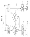
- a ram cylinder control system for a wheel type excavator having brakes, a joy stick and ram cylinders for supporting an upper frame of a vehicle body, comprising: a pilot hydraulic pump; pilot-opened check valves for normally prohibiting discharge of working fluid from the ram cylinders to lock the ram cylinders; a ram cylinder control valve adapted to shift from a home position to an operating position in response to a valve control signal for allowing the hydraulic oil from the pilot hydraulic pump to open the check valves so that the hydraulic oil can be discharged from the ram cylinders; brake pressure sensing means for detecting hydraulic oil pressure supplied to the brakes; joystick position detector means for detecting position of the joystick to generate one of a forward position signal, a backward position signal and a neutral signal; and a controller for applying the valve control signal to the ram cylinder control valve if the forward position signal or the backward position signal is generated from the joystick position
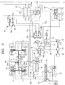
- a hydraulic circuit diagram of a ram cylinder control system for a wheel type excavator according to the present invention.
- the ram cylinder control system for a wheel type excavator comprises a main hydraulic pump for supplying hydraulic oil to various hydraulic actuators such as a travel motor 1, a pilot hydraulic pump 20 for supplying pilot pressure to control valves, and an auxiliary pump 30 for supplying hydraulic pressure to brakes 5 provided on vehicle axles 4.
- a brake pressure sensor 17 is provided between brake lines 16a, 16b for feeding the brakes 5 with the hydraulic oil from the auxiliary pump 30.
- the brake pressure sensor 17 is adapted to detect a brake pressure in the brake lines 16a, 16b, whichever is higher, and then input a corresponding signal into a controller 19 described later.
- this joystick 26 is positioned at the forward position or the backward position and thus the forward position signal or the backward position signal is generated, the signal is supplied to the forward control valve 25a or the backward control valve 25b through the controller 19 described later, thereby shifting the corresponding one of the traveling control valves 25a, 25b.
- the forward control valve 25a or the backward control valve 25b is shifted, the hydraulic oil from the pilot hydraulic pump 20 acts as the forward pilot pressure or the backward pilot pressure through the traveling control pilot line 27a or 27b. If the joystick 26 is positioned at the neutral position 26c, no traveling signal is fed to the traveling control valves 25a, 25b.
- connection lines 24a has a pair of check valves 24b that normally block off the discharge of hydraulic oil from each of the ram cylinders 24.
- the ram cylinder control valve 29 is always resiliently biased to the home position 29b by a return spring 29c provided at one side of the control valve 29. In addition, if a signal is applied to a solenoid part 29d, the ram cylinder control valve 29 is shifted toward the operating position 29a. The solenoid part 29d is activated if a ram cylinder-locking signal is applied from the controller 19.
- ram cylinder control valve 29 if a ram cylinder releasing signal is applied to the solenoid part 29d from the controller 19, the ram cylinder control valve 29 is shifted to the operating position 29 and thus releases the ram cylinders 24, but if no ram cylinder releasing signal is applied to the solenoid part 29d from the controller, the ram cylinder control valve 29 returns to its home position 29b and thus causes the ram cylinders 24 to be locked.
Landscapes
- Engineering & Computer Science (AREA)
- Mining & Mineral Resources (AREA)
- Civil Engineering (AREA)
- General Engineering & Computer Science (AREA)
- Structural Engineering (AREA)
- Operation Control Of Excavators (AREA)
Claims (6)
- Arbeitszylinder-Steuersystem für einen Radbagger, der Bremsen (5), einen Joystick (26) und Arbeitszylinder (24) zum Unterstützen eines oberen Rahmens einer Fahrzeugkarosserie besitzt, mit:einer Vorsteuer-Hydraulikpumpe (20);durch Vorsteuerung zu öffnenden Rückschlagventilen (24b), um den Ausstoß von Arbeitsfluid von dem Arbeitszylinder (24) normalerweise zu verhindern, um die Arbeitszylinder (24) zu verriegeln;einem Arbeitszylinder-Steuerventil (29), das ausgelegt ist, um sich in Reaktion auf ein Ventilsteuersignal aus einer Ruheposition in eine Arbeitsposition (29a) zu verschieben, um zuzulassen, dass das Hydrauliköl von der Vorsteuer-Hydraulikpumpe (20) die Rückschlagventile öffnet, damit Hydrauliköl von den Arbeitszylindern (24) ausgestoßen werden kann; undJoystickpositions-Detektormitteln zum Erfassen der Position des Joysticks, um entweder ein Vorwärtspositionssignal, ein Rückwärtspositionssignal oder ein Neutralsignal zu erzeugen;dadurch gekennzeichnet, dass es ferner umfasst:Bremsdruck-Erfassungsmittel zum Erfassen von Hydrauliköldruck, der an die Bremsen angelegt wird;eine Steuereinheit (19) zum Eingeben des Ventilsteuersignals in das Arbeitszylinder-Steuerventil (29), falls das Vorwärtspositionssignal oder das Rückwärtspositionssignal von den Joystickpositions-Detektormitteln erzeugt wird und falls der durch die Bremsdruck-Erfassungsmittel erfasste Bremsdruck nicht größer als ein Solldruck ist, und zum Unterbrechen des Ventilsteuersignals, das in das Arbeitszylinder-Steuerventil (29) eingegeben wird, falls das Neutralsignal von den Joystickpositions-Detektormitteln erzeugt wird und falls der Bremsdruck den Solldruck übersteigt.
- System nach Anspruch 1, wobei die Steuereinheit (19) ausgelegt ist, um das Ventilsteuersignal, das in das Arbeitszylinder-Steuerventil (29) eingegeben wird, selbst dann zu unterbrechen, wenn das Vorwärtspositionssignal oder das Rückwärtspositionssignal von den Joystickpositions-Detektormittein erzeugt wird, sofern der Bremsdruck den Solldruck übersteigt.
- System nach Anspruch 1 oder 2, wobei die Steuereinheit (19) eine automatische Betriebsart besitzt, um das Ventilsteuersignal in das Arbeitszylinder-Steuerventil (29) in Abhängigkeit von den Signalen von den Bremsdruck-Erfassungsmitteln und von den Joystickpositions-Detektormitteln einzugeben oder zu unterbrechen, eine feste Freigabebetriebsart hat, um das Ventilsteuersignal unabhängig von den Signalen von den Bremsdruck-Erfassungsmitteln und dem Joystick-Steuersignal, das in das Arbeitszylinder-Steuerventil (29) unabhängig von den Signalen von den Bremsdruck-Erfassungsmitteln und den Joystickpositions-Detektormitteln eingegeben wird, in das Arbeitszylinder-Steuerventil (29) einzugeben.
- System nach Anspruch 3, das ferner einen Betriebsartauswahlschalter (33) umfasst, um einer Bedienungsperson zu ermöglichen, entweder die automatische Betriebsart oder die feste Freigabebetriebsart oder die feste Verriegelungsbetriebsart auszuwählen.
- System nach einem der Ansprüche 1 bis 4, wobei die Steuereinheit (19) eine Freigabebetriebsart hat, um das Ventilsteuersignal in das Arbeitszylinder-Steuerventil (29) in Abhängigkeit von den Signalen von den Bremsdruck-Erfassungsmitteln und den Joystickpositions-Detektormitteln einzugeben oder zu unterbrechen, und eine feste Verriegelungsbetriebsart hat, um das Ventilsteuersignal, das in das Arbeitszylinder-Steuerventil (29) eingegeben wird, unabhängig von den Signalen von den Bremsdruck-Erfassungsmitteln und von den Joystickpositions-Detektormittein zu unterbrechen.
- System nach Anspruch 5, das ferner einen Betriebsartauswahlschalter (33) umfasst, um einer Bedienungsperson zu ermöglichen, entweder die Freigabebetriebsart oder die feste Verriegelungsbetriebsart zu wählen.
Applications Claiming Priority (2)
| Application Number | Priority Date | Filing Date | Title |
|---|---|---|---|
| KR1020030098611A KR100988420B1 (ko) | 2003-12-29 | 2003-12-29 | 휠타입 굴삭기의 램실린더 제어장치 |
| KR2003098611 | 2003-12-29 |
Publications (3)
| Publication Number | Publication Date |
|---|---|
| EP1550774A2 EP1550774A2 (de) | 2005-07-06 |
| EP1550774A3 EP1550774A3 (de) | 2005-08-10 |
| EP1550774B1 true EP1550774B1 (de) | 2008-03-26 |
Family
ID=34567846
Family Applications (1)
| Application Number | Title | Priority Date | Filing Date |
|---|---|---|---|
| EP04030864A Ceased EP1550774B1 (de) | 2003-12-29 | 2004-12-28 | Steuersystem eines Stempels eines Radladers |
Country Status (5)
| Country | Link |
|---|---|
| EP (1) | EP1550774B1 (de) |
| JP (1) | JP2005194870A (de) |
| KR (1) | KR100988420B1 (de) |
| CN (1) | CN100591871C (de) |
| DE (1) | DE602004012700T2 (de) |
Cited By (2)
| Publication number | Priority date | Publication date | Assignee | Title |
|---|---|---|---|---|
| CN102338134A (zh) * | 2011-10-24 | 2012-02-01 | 中联重科股份有限公司 | 混凝土泵送设备及其泵送油缸的换向控制方法 |
| WO2016032811A1 (en) * | 2014-08-27 | 2016-03-03 | Caterpillar Inc. | Hydraulic winch control system and method |
Families Citing this family (7)
| Publication number | Priority date | Publication date | Assignee | Title |
|---|---|---|---|---|
| KR100753988B1 (ko) * | 2006-06-09 | 2007-08-31 | 볼보 컨스트럭션 이키프먼트 홀딩 스웨덴 에이비 | 건설중장비용 엑슬 록킹 실린더 구조 |
| JP4944537B2 (ja) * | 2006-08-09 | 2012-06-06 | 日立建機株式会社 | 油圧駆動車両の走行制御装置 |
| DE102007018405B4 (de) * | 2007-04-17 | 2022-09-15 | Alpha Fluid Hydrauliksysteme Müller GmbH | Elektrohydraulische Ansteuerung |
| KR102042285B1 (ko) * | 2013-12-26 | 2019-11-27 | 두산인프라코어 주식회사 | 휠 타입 건설기계의 램실린더 제어 장치 및 그 방법 |
| CN105351272B (zh) * | 2015-12-11 | 2017-05-24 | 重庆纳川山隅重工设备有限公司 | 液压凿岩钻机的自适应阀组 |
| KR102533655B1 (ko) * | 2016-09-05 | 2023-05-17 | 에이치디현대인프라코어 주식회사 | 건설 기계 |
| CN116241516B (zh) * | 2022-12-26 | 2025-08-15 | 中国铁建重工集团股份有限公司 | 掘锚机泵站的控制系统、掘锚机 |
Family Cites Families (9)
| Publication number | Priority date | Publication date | Assignee | Title |
|---|---|---|---|---|
| JPS55114610A (en) * | 1979-02-21 | 1980-09-04 | Kubota Ltd | Working car |
| NL8200556A (nl) * | 1982-02-13 | 1983-09-01 | Rotterdamsche Droogdok Mij | Voertuig. |
| US4835970A (en) * | 1985-08-13 | 1989-06-06 | Nissan Motor Co. Ltd. | Pneumatic power brake system |
| JPS6361621A (ja) | 1986-09-02 | 1988-03-17 | Hitachi Constr Mach Co Ltd | 作業車両のラムロツク制御装置 |
| JP2937329B2 (ja) * | 1987-10-26 | 1999-08-23 | 日立建機株式会社 | 作業車両のラムロック制御装置 |
| JPH0662269B2 (ja) * | 1989-04-21 | 1994-08-17 | 株式会社神戸製鋼所 | 移動式クレーンの変位抑制装置 |
| KR970040698A (ko) | 1995-12-29 | 1997-07-24 | 유상부 | 휠타입 굴삭기의 작업브레이크장치 |
| US6592190B2 (en) * | 2001-07-11 | 2003-07-15 | Deere & Company | Secondary brake system with electrohydraulic proportional valve |
| KR200315168Y1 (ko) | 2003-02-19 | 2003-06-02 | 정권철 | 굴삭기의 차축 록킹제어장치 |
-
2003
- 2003-12-29 KR KR1020030098611A patent/KR100988420B1/ko not_active Expired - Fee Related
-
2004
- 2004-12-28 DE DE602004012700T patent/DE602004012700T2/de not_active Expired - Lifetime
- 2004-12-28 JP JP2004380109A patent/JP2005194870A/ja active Pending
- 2004-12-28 EP EP04030864A patent/EP1550774B1/de not_active Ceased
- 2004-12-29 CN CN200410104956A patent/CN100591871C/zh not_active Expired - Fee Related
Cited By (3)
| Publication number | Priority date | Publication date | Assignee | Title |
|---|---|---|---|---|
| CN102338134A (zh) * | 2011-10-24 | 2012-02-01 | 中联重科股份有限公司 | 混凝土泵送设备及其泵送油缸的换向控制方法 |
| CN102338134B (zh) * | 2011-10-24 | 2013-08-21 | 中联重科股份有限公司 | 混凝土泵送设备及其泵送油缸的换向控制方法 |
| WO2016032811A1 (en) * | 2014-08-27 | 2016-03-03 | Caterpillar Inc. | Hydraulic winch control system and method |
Also Published As
| Publication number | Publication date |
|---|---|
| JP2005194870A (ja) | 2005-07-21 |
| CN1637211A (zh) | 2005-07-13 |
| DE602004012700D1 (de) | 2008-05-08 |
| KR100988420B1 (ko) | 2010-10-18 |
| KR20050067620A (ko) | 2005-07-05 |
| CN100591871C (zh) | 2010-02-24 |
| EP1550774A3 (de) | 2005-08-10 |
| EP1550774A2 (de) | 2005-07-06 |
| DE602004012700T2 (de) | 2009-04-16 |
Similar Documents
| Publication | Publication Date | Title |
|---|---|---|
| KR101970855B1 (ko) | 작업 차량의 제어 장치 | |
| EP2805858B1 (de) | Hydraulische steuervorrichtung für eine arbeitsmaschine | |
| EP2334525B1 (de) | Verfahren zum betrieb eines bremssystems einer arbeitsmaschine und bremssystem für eine arbeitsmaschine | |
| JP7572874B2 (ja) | 作業機械の制御システム、作業機械の制御方法、および作業機械 | |
| EP1550774B1 (de) | Steuersystem eines Stempels eines Radladers | |
| JP4373820B2 (ja) | 作業機械の前後進操作装置 | |
| WO2017068083A1 (en) | A powered vehicle including a sahr brake | |
| KR101068920B1 (ko) | 작업차량의 제어장치 | |
| KR101007484B1 (ko) | 엔진지게차의 안전제어방법 | |
| US6062331A (en) | Auxiliary hydraulic control system for a work machine | |
| JP4758075B2 (ja) | 作業車両の制御装置 | |
| JP4361422B2 (ja) | 作業車両 | |
| KR102815684B1 (ko) | 경사 각도 센싱을 통한 휠 굴삭기의 자동 파킹 브레이크 시스템 | |
| JP2007051652A (ja) | 作業車両の制御装置 | |
| KR100976925B1 (ko) | 휠타입 굴삭기의 램실린더 제어장치 | |
| JP5973326B2 (ja) | 作業車両のブレーキ制御装置 | |
| US9555784B2 (en) | Braking system and method for machine | |
| JP5156811B2 (ja) | 作業車両の制御装置 | |
| KR100976926B1 (ko) | 휠타입 굴삭기의 램실린더 제어장치 | |
| KR20160119486A (ko) | 유압 브레이크 장치 |
Legal Events
| Date | Code | Title | Description |
|---|---|---|---|
| PUAI | Public reference made under article 153(3) epc to a published international application that has entered the european phase |
Free format text: ORIGINAL CODE: 0009012 |
|
| PUAL | Search report despatched |
Free format text: ORIGINAL CODE: 0009013 |
|
| AK | Designated contracting states |
Kind code of ref document: A2 Designated state(s): AT BE BG CH CY CZ DE DK EE ES FI FR GB GR HU IE IS IT LI LT LU MC NL PL PT RO SE SI SK TR |
|
| AX | Request for extension of the european patent |
Extension state: AL BA HR LV MK YU |
|
| AK | Designated contracting states |
Kind code of ref document: A3 Designated state(s): AT BE BG CH CY CZ DE DK EE ES FI FR GB GR HU IE IS IT LI LT LU MC NL PL PT RO SE SI SK TR |
|
| AX | Request for extension of the european patent |
Extension state: AL BA HR LV MK YU |
|
| RAP1 | Party data changed (applicant data changed or rights of an application transferred) |
Owner name: DOOSAN INFRACORE CO., LTD. |
|
| 17P | Request for examination filed |
Effective date: 20060209 |
|
| AKX | Designation fees paid |
Designated state(s): DE FR GB IT |
|
| GRAP | Despatch of communication of intention to grant a patent |
Free format text: ORIGINAL CODE: EPIDOSNIGR1 |
|
| GRAS | Grant fee paid |
Free format text: ORIGINAL CODE: EPIDOSNIGR3 |
|
| GRAA | (expected) grant |
Free format text: ORIGINAL CODE: 0009210 |
|
| AK | Designated contracting states |
Kind code of ref document: B1 Designated state(s): DE FR GB IT |
|
| REG | Reference to a national code |
Ref country code: GB Ref legal event code: FG4D |
|
| REF | Corresponds to: |
Ref document number: 602004012700 Country of ref document: DE Date of ref document: 20080508 Kind code of ref document: P |
|
| ET | Fr: translation filed | ||
| PLBE | No opposition filed within time limit |
Free format text: ORIGINAL CODE: 0009261 |
|
| STAA | Information on the status of an ep patent application or granted ep patent |
Free format text: STATUS: NO OPPOSITION FILED WITHIN TIME LIMIT |
|
| 26N | No opposition filed |
Effective date: 20081230 |
|
| REG | Reference to a national code |
Ref country code: FR Ref legal event code: PLFP Year of fee payment: 12 |
|
| REG | Reference to a national code |
Ref country code: FR Ref legal event code: PLFP Year of fee payment: 13 |
|
| REG | Reference to a national code |
Ref country code: FR Ref legal event code: PLFP Year of fee payment: 14 |
|
| PGFP | Annual fee paid to national office [announced via postgrant information from national office to epo] |
Ref country code: FR Payment date: 20211224 Year of fee payment: 18 Ref country code: GB Payment date: 20211216 Year of fee payment: 18 |
|
| PGFP | Annual fee paid to national office [announced via postgrant information from national office to epo] |
Ref country code: DE Payment date: 20211222 Year of fee payment: 18 |
|
| PGFP | Annual fee paid to national office [announced via postgrant information from national office to epo] |
Ref country code: IT Payment date: 20211230 Year of fee payment: 18 |
|
| P01 | Opt-out of the competence of the unified patent court (upc) registered |
Effective date: 20230523 |
|
| REG | Reference to a national code |
Ref country code: DE Ref legal event code: R119 Ref document number: 602004012700 Country of ref document: DE |
|
| GBPC | Gb: european patent ceased through non-payment of renewal fee |
Effective date: 20221228 |
|
| PG25 | Lapsed in a contracting state [announced via postgrant information from national office to epo] |
Ref country code: GB Free format text: LAPSE BECAUSE OF NON-PAYMENT OF DUE FEES Effective date: 20221228 Ref country code: DE Free format text: LAPSE BECAUSE OF NON-PAYMENT OF DUE FEES Effective date: 20230701 |
|
| PG25 | Lapsed in a contracting state [announced via postgrant information from national office to epo] |
Ref country code: FR Free format text: LAPSE BECAUSE OF NON-PAYMENT OF DUE FEES Effective date: 20221231 |
|
| PG25 | Lapsed in a contracting state [announced via postgrant information from national office to epo] |
Ref country code: IT Free format text: LAPSE BECAUSE OF NON-PAYMENT OF DUE FEES Effective date: 20221228 |