EP1548316B1 - Scheibenbremse. - Google Patents
Scheibenbremse. Download PDFInfo
- Publication number
- EP1548316B1 EP1548316B1 EP04028116A EP04028116A EP1548316B1 EP 1548316 B1 EP1548316 B1 EP 1548316B1 EP 04028116 A EP04028116 A EP 04028116A EP 04028116 A EP04028116 A EP 04028116A EP 1548316 B1 EP1548316 B1 EP 1548316B1
- Authority
- EP
- European Patent Office
- Prior art keywords
- caliper
- disc
- recess
- bore
- passage opening
- Prior art date
- Legal status (The legal status is an assumption and is not a legal conclusion. Google has not performed a legal analysis and makes no representation as to the accuracy of the status listed.)
- Expired - Lifetime
Links
- 238000004891 communication Methods 0.000 claims description 49
- 238000005266 casting Methods 0.000 claims description 35
- 238000003754 machining Methods 0.000 claims description 15
- 230000005484 gravity Effects 0.000 claims description 7
- 238000004519 manufacturing process Methods 0.000 claims description 6
- 238000005520 cutting process Methods 0.000 description 7
- 230000000694 effects Effects 0.000 description 4
- 239000012530 fluid Substances 0.000 description 4
- 238000003801 milling Methods 0.000 description 4
- VYPSYNLAJGMNEJ-UHFFFAOYSA-N Silicium dioxide Chemical compound O=[Si]=O VYPSYNLAJGMNEJ-UHFFFAOYSA-N 0.000 description 2
- 229910000838 Al alloy Inorganic materials 0.000 description 1
- 239000006004 Quartz sand Substances 0.000 description 1
- 238000010276 construction Methods 0.000 description 1
- 238000003780 insertion Methods 0.000 description 1
- 230000037431 insertion Effects 0.000 description 1
- 239000011347 resin Substances 0.000 description 1
- 229920005989 resin Polymers 0.000 description 1
- 239000004576 sand Substances 0.000 description 1
- 239000007787 solid Substances 0.000 description 1
Images


Classifications
-
- F—MECHANICAL ENGINEERING; LIGHTING; HEATING; WEAPONS; BLASTING
- F16—ENGINEERING ELEMENTS AND UNITS; GENERAL MEASURES FOR PRODUCING AND MAINTAINING EFFECTIVE FUNCTIONING OF MACHINES OR INSTALLATIONS; THERMAL INSULATION IN GENERAL
- F16D—COUPLINGS FOR TRANSMITTING ROTATION; CLUTCHES; BRAKES
- F16D55/00—Brakes with substantially-radial braking surfaces pressed together in axial direction, e.g. disc brakes
- F16D55/02—Brakes with substantially-radial braking surfaces pressed together in axial direction, e.g. disc brakes with axially-movable discs or pads pressed against axially-located rotating members
- F16D55/22—Brakes with substantially-radial braking surfaces pressed together in axial direction, e.g. disc brakes with axially-movable discs or pads pressed against axially-located rotating members by clamping an axially-located rotating disc between movable braking members, e.g. movable brake discs or brake pads
- F16D55/228—Brakes with substantially-radial braking surfaces pressed together in axial direction, e.g. disc brakes with axially-movable discs or pads pressed against axially-located rotating members by clamping an axially-located rotating disc between movable braking members, e.g. movable brake discs or brake pads with a separate actuating member for each side
-
- F—MECHANICAL ENGINEERING; LIGHTING; HEATING; WEAPONS; BLASTING
- F16—ENGINEERING ELEMENTS AND UNITS; GENERAL MEASURES FOR PRODUCING AND MAINTAINING EFFECTIVE FUNCTIONING OF MACHINES OR INSTALLATIONS; THERMAL INSULATION IN GENERAL
- F16D—COUPLINGS FOR TRANSMITTING ROTATION; CLUTCHES; BRAKES
- F16D55/00—Brakes with substantially-radial braking surfaces pressed together in axial direction, e.g. disc brakes
- F16D2055/0004—Parts or details of disc brakes
- F16D2055/0016—Brake calipers
- F16D2055/002—Brake calipers assembled from a plurality of parts
-
- F—MECHANICAL ENGINEERING; LIGHTING; HEATING; WEAPONS; BLASTING
- F16—ENGINEERING ELEMENTS AND UNITS; GENERAL MEASURES FOR PRODUCING AND MAINTAINING EFFECTIVE FUNCTIONING OF MACHINES OR INSTALLATIONS; THERMAL INSULATION IN GENERAL
- F16D—COUPLINGS FOR TRANSMITTING ROTATION; CLUTCHES; BRAKES
- F16D55/00—Brakes with substantially-radial braking surfaces pressed together in axial direction, e.g. disc brakes
- F16D2055/0075—Constructional features of axially engaged brakes
- F16D2055/0091—Plural actuators arranged side by side on the same side of the rotor
-
- F—MECHANICAL ENGINEERING; LIGHTING; HEATING; WEAPONS; BLASTING
- F16—ENGINEERING ELEMENTS AND UNITS; GENERAL MEASURES FOR PRODUCING AND MAINTAINING EFFECTIVE FUNCTIONING OF MACHINES OR INSTALLATIONS; THERMAL INSULATION IN GENERAL
- F16D—COUPLINGS FOR TRANSMITTING ROTATION; CLUTCHES; BRAKES
- F16D2250/00—Manufacturing; Assembly
- F16D2250/0007—Casting
-
- Y—GENERAL TAGGING OF NEW TECHNOLOGICAL DEVELOPMENTS; GENERAL TAGGING OF CROSS-SECTIONAL TECHNOLOGIES SPANNING OVER SEVERAL SECTIONS OF THE IPC; TECHNICAL SUBJECTS COVERED BY FORMER USPC CROSS-REFERENCE ART COLLECTIONS [XRACs] AND DIGESTS
- Y10—TECHNICAL SUBJECTS COVERED BY FORMER USPC
- Y10T—TECHNICAL SUBJECTS COVERED BY FORMER US CLASSIFICATION
- Y10T29/00—Metal working
- Y10T29/49—Method of mechanical manufacture
- Y10T29/4998—Combined manufacture including applying or shaping of fluent material
- Y10T29/49988—Metal casting
- Y10T29/49989—Followed by cutting or removing material
Definitions
- the present invention relates to a disc brake for a vehicle.
- a pair of pads are disposed on opposite sides of a disc, and pistons , each of which is disposed on a side opposite to the disc relative to the corresponding pad, are adapted to press the pads against the disc, to thereby apply a braking force to the vehicle.
- the pistons are slidably fitted into bores formed in a caliper body.
- a bottom portion of each of the bores for the pistons is formed by a member externally attached to an open end of the bore.
- a tool is inserted from the open end of the bore, and a passage opening is formes by cutting from a portion in the bore on a side of the bottom portion thereof, and then the bore is closed by threadably engaging the bottom portion with the caliper body.
- the passage opening must be formed by cutting from a predetermined position, in the bore while avoiding interference with the open end of the bore before it is closed. Therefore, the passage opening must be formed with high machining accuracy and an operation for forming the passage opening becomes cumbersome. This lowers production efficiency. Further, since the passage opening must be formed while avoiding interference with the open end of the bore, a degree of freedom of design when determining the Position of the passage opening is low.
- the disclosed embodiments of the present invention provide a disc brake in which an opening for forming a brake fluid passage can be easily formed, thus achieving high production efficiency, and which enables the position of the opening for the brake fluid passage to be determined with a high degree of freedom of design.
- a disc brake comprising a pair of pads disposable on opposite sides of a disc; a caliper disposable so as to extend over the disc, the caliper being adapted to be mounted on a vehicle; and pistons including at least one piston slidably held in each side of the caliper to be disposed on each side of the disc, each piston being located on a side of the corresponding pad opposite to the side of each pad that is configured to contact the disc, the caliper including machined bores including at least one machined bore on each side of the disc, each machined bore being machined from a prepared hole, into which the at least one piston on each side is slidably fitted, cf. EP-A-907034 .
- the invention according to claim 1 is characterised in that the caliper further comprises a recess formed on each side of the disc together with the prepared hole by means of a core when the caliper is cast so that it extends from a part of the circumference of a bottom portion of the prepared hole outwardly in a radial direction of the prepared hole; a linear passage opening formed by boring so as to extend from an exterior surface of the caliper to the recess on one side of the disc, and another linear passage opening in communication with the linear passage opening, the another linear passage opening being formed by boring so as to extend from the exterior surface of the caliper to the recess on the other side of the disc, wherein the bores on the respective sides of the disc are in communication with each other through the linear passage opening and the another linear passage opening.
- a cast caliper to be machined to form a caliper for a disc brake comprising prepared holes including at least one prepared hole formed on each side of the space to which a disc is inserted when the cast caliper is mounted on a vehicle, said at least one prepared hole adapted to be machined to form at least one bore into which a piston can be slidably fitted; a recess formed on each side of said cast caliper together with one prepared hole by means of a core when the caliper is cast, the recess extending from a part of the circumference of a bottom portion of the prepared hole outwardly in a radial direction of the prepared hole.
- a method of manufacturing a disc brake comprising the steps of casting a caliper in a mould including a core so as to form a cast caliper including at least one prepared hole and a recess extending from a part of the circumference of a bottom portion of the prepared hole outwardly in a radial direction of the prepared hole on each side of a space to which the disc will be inserted when the caliper is mounted on a vehicle; machining each prepared hole to form a bore into which a piston can be slidably fitted; and boring at least two linear passage openings communicable with each other in the cast caliper to extend from an exterior surface of the caliper to each recess.
- the following describes a disc brake comprising a pair of pads disposed on opposite sides of a disc, a caliper disposed so as to extend over the disc, the caliper being adapted to be mounted on a vehicle body, and at least one piston slidably held in the caliper, the piston being located on a side opposite to the disc relative to the corresponding pad.
- the caliper includes a prepared hole to be machined to form at least one bore into which the piston is slidably fitted, and a recess extending from a bottom portion of the prepared hole outwardly in a radiale direction of the prepared hole.
- the prepared hole and the recess are formed by means of a core when the caliper is cast.
- a linear passage opening is formed so as to extend from an exterior surface of the caliper to the recess.
- the caliper includes a plurality of bores arranged in a spaced relationship in a direction of rotation of the disc, and a communication passage for communication between the adjacent bores is formed in the caliper by means of the core when the caliper is cast.
- the recess is formed at a position corresponding to the top of the uppermost bore when the caliper is mounted on the vehicle body.
- the passage opening is formed so as to extend from the exterior surface of a portion of the caliper that is located at an upper position when the caliper is mounted on the vehicle body.
- the plurality of bores are disposed on each of opposite sides of the disc in an axial direction of the disc, and a linear communication opening is formed so as to extend from the exterior surface of the caliper and to intersect the passage opening.
- the communication opening is adapted to form a part of a connection passage for allowing communication between the bores disposed on opposite sides of the disc in the axial direction of the disc.
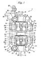
- reference numeral 1 denotes an opposed-piston type disc brake.
- a caliper 11 of this disc brake is an opposed-piston type caliper 11.
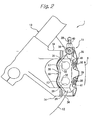
- the caliper 11 comprises a caliper body 16 which extends over a disc 12, as shown in Fig. 1 , and which is mounted on a mount portion 14 of a front fork 13 as a non-rotational portion of a body of a vehicle (a motor cycle in this embodiment), as shown in Fig. 2 .
- the caliper 11 further comprises a plurality of pairs (two pairs in this embodiment) of pistons 17 slidably provided in the caliper body 16, so as to face each other with the disc 12 being disposed therebetween.
- a radial direction of the disc 12, an axial direction of the disc 12, a direction of rotation of the disc 12 refer to those in a state in which the caliper body is mounted on a vehicle body.
- an arrow R indicates the direction of rotation of the disc 12 when a vehicle travels in a forward direction.
- the caliper body 16 is a one-piece member comprising an outer-side cylinder portion 20 disposed on an outer side of the disc 12 (a side opposite to a wheel) and an inner-side cylinder portion 21 disposed on an inner side of the disc 12 (a side on which a wheel is provided).
- the caliper body 16 further comprises a plurality (three in this embodiment) of outer-side torque bearing portions 23 projecting from the outer-side cylinder portion 20 towards the inner side of the disc, the outer-side torque bearing portions 23 being arranged in a spaced relationship in a direction of rotation of the disc 12, a plurality (three in this embodiment) of inner-side torque bearing portions 24 projecting from the inner-side cylinder portion 21 towards the outer side of the disc, the inner-side torque bearing portions 24 being arranged in a spaced relationship in a direction of rotation of the disc 12, and a plurality (three in this embodiment) of disc pass portions 26, each connecting the outer-side torque bearing portion 23 and the inner-side torque bearing portion 24 corresponding to each other in terms of a position in the direction of rotation of the disc.
- the outer-side torque bearing portions 23 and the inner-side torque bearing portions 24 are provided between the outer-side cylinder portion 20 and the inner-side cylinder portion 21, and the disc pass portions 26 are provided between the outer-side torque bearing portions 23 and the inner-side torque bearing portions 24 and connect the outer-side torque bearing portions 23 and the inner-side torque bearing portions 24.
- a plurality (three in this embodiment) of portions are arranged in a spaced relationship in a direction of rotation of the disc 12, each of which portions comprises the outer-side torque bearing portion 23, the disc pass portion 26 and the inner-side torque bearing portion 24 extending in an axial direction of the disc 12.
- a pad-mounting space 28 is formed between each pair of adjacent ones of these portions, which space 28 has an opening facing in a radial direction of the disc 12.
- opposed surfaces 20a and 21a of the outer-side and inner-side cylinder portions 20 and 21 face each other through each pad-mounting space 28.
- a pad pin 30 extends in an axial direction of the disc through the pad-mounting space 28 between the opposed surfaces 20a and 21a.
- Bores 31 are formed in the opposed surfaces 20a and 21a of the outer-side and inner-side cylinder portions 20 and 21, which surfaces face each other through each pad-mounting space 28.
- Each bore 31 has a center axis parallel to an axial direction of the disc.
- the pistons 17 are fitted into inner-diameter portions 32 of the bores 31.
- a plurality of pairs (two pairs in this embodiment) of bores 31 are arranged in a direction of rotation of the disc, with the bores 31 of each pair facing each other in an axial direction of the disc.
- a plurality of pairs (two pairs in this embodiment) of pistons 17 are arranged in a direction of rotation of the disc, with the pistons 17 of each pair facing each other in an axial direction of the disc.
- a pair of pads 33 are supported on each pad pin 30 of the caliper body 16. Thus, totally two pairs of pads 33 are provided in the caliper body 16.
- the pads 33 are adapted to slidably move in an axial direction of the disc.
- the pads 33 are respectively disposed on opposite sides of the disc 12 in an axial direction of the disc.
- the pistons 17, each of which is disposed on a side opposite to the disc 12 relative to the corresponding pad 33, are adapted to press the pads 33 against the disc 12, thus applying a braking force to the vehicle.
- a braking torque during braking when the vehicle travels in a forward direction acts as a force which moves the pads 33 from an entrance side of the disc 12 in a direction of rotation of the disc (hereinafter, referred to simply as “the entrance side of the disc”) to an exit side of the disc 12 in the direction of rotation of the disc (hereinafter, referred to simply as “the exit side of the disc”).
- This force is transmitted from the pair of pads 33 on the exit side of the disc to the caliper body 16 through the outer-side torque bearing portion 23 and the inner-side torque bearing portion 24 which are located most closely to the exit side of the disc and abut against these pads 33.
- the force is also transmitted from the pair of pads 33 on the entrance side of the disc to the caliper body 16 through the outer-side torque bearing portion 23 and the inner-side torque bearing portion 24 which are located at an intermediate position in a direction of rotation of the disc and abut against these pads 33.
- a braking torque during braking is transmitted from the pads 33 to the caliper body 16 through the outer-side torque bearing portions 23 and the inner-side torque bearing portions 24 which abut against the pads 33 on a side opposite to those which abut against the pads 33 when the vehicle travels in a forward direction.
- an inner side (as viewed in a radial direction of the disc) of the disc pass portion 26 of the caliper body 16 includes a pass recess 34 in which the disc 12 is provided.
- the outer-side torque bearing portion 23 and the inner-side torque bearing portion 24 extend beyond the disc pass portion 26 inwardly in a radial direction of the disc, so as to enable the torque from the pads 33 disposed in an overlapping relation to the disc 12 in a radial direction of the disc to be received in a direction of rotation of the disc. That is, a wall thickness of the disc pass portion 26 in a radial direction of the disc is smaller than that of each of the outer-side torque bearing portion 23 and the inner-side torque bearing portion 24.
- a pad spring 35 is disposed so as to bias the pads 33 inwardly in a radial direction of the disc.
- the disc brake 1 comprises a pair of pads 33 disposed on opposite sides of the disc 12, a caliper body 16 disposed so as to extend over the disc 12, and pistons 17, each of which is slidably held on a side opposite to the disc 12 relative to the corresponding pad 33.
- a plurality of bores 31 are disposed in a spaced relationship in a direction of rotation of the disc.
- An inner-side torque bearing portion 24, a disc pass portion 26 and an outer-side torque bearing portion 23 are disposed between the bores 31 adjacent to each other in a direction of rotation of the disc.
- the outer-side cylinder portion 20 of the caliper body 16 includes a plurality (two in this embodiment) of mounting bolt openings 37 for mounting of the caliper 11 on the mount portion 14 of the front fork 13.
- the mounting bolt openings 37 are formed in parallel to each other in the radial direction of the disc.
- the outer-side cylinder portion 20 of the caliper body 16 includes a pipe mount opening 38 for mounting of a brake pipe, which opening extends in an axial direction of the disc.
- the pipe mount opening 38 is formed at a position which corresponds to an upper position when the caliper body is mounted on the front fork 13 and which is located on the exit side of the disc during braking when the vehicle travels in a forward direction.
- a bleeder mounting opening 40 for mounting a bleeder plug 39 for release of air is vertically formed at an upper end position above the pipe mount opening 38.
- the outer-side cylinder portion 20 and the inner-side cylinder portion 21 of the caliper body 16 include pad pin holes 41 for mounting of the pad pins 30.
- the pad pin holes 41 extend in an axial direction of the disc.
- the outer-side cylinder portion 20, the inner-side cylinder portion 21, all the outer-side torque bearing portions 23, all the inner-side torque bearing portions 24 and all the disc pass portions 26 are cast into a one-piece member, which forms the caliper body 16.
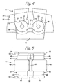
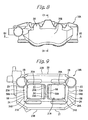
- a core 44 shown in Figs. 4 to 6 is used.
- the core 44 comprises a base portion 45, a plurality (two in this embodiment) of pad-mounting space forming portions 46 extending from the base portion 45 in the same direction while being spaced from each other, and a plurality (four in this embodiment) of prepared hole forming portions 47 extending in opposite directions beyond the pad-mounting space forming portions 46 so as to orthogonally intersect the direction of array of the pad-mounting space forming portions 46.
- Each prepared hole forming portion 47 comprises an inner-diameter prepared hole forming portion 49 having a solid cylindrical body and an inmost recess forming portion 50 in a disc-like form, the inmost recess forming portion being formed in the inner-diameter prepared hole forming portion 49 on a side opposite to the pad-mounting space forming portion 46 in a coaxial relationship to the inner-diameter prepared hole forming portion 49.
- the inmost recess forming portion 50 has a larger diameter than the inner-diameter prepared hole forming portion 49 and also has a larger diameter than the inner-diameter portion 32 of the bore 31 after machining of an inner surface of a prepared hole.
- the core 44 comprises communication passage forming portions 51, each connecting proximately opposed portions of the adjacent inmost recess forming portions 50 arranged on the same side of the core 44, recess forming portions 52 extending from the inmost recess forming portions 50 disposed on opposite sides of one pad-mounting space forming portion 46.
- Each recess forming portion 52 extends from the corresponding inmost recess forming portion 50 on a side opposite to the communication passage forming portion 51 outwardly as viewed in a radial direction of the inmost recess forming portion 50.
- the recess forming portion 52 has a substantially tapered triangular form projecting from the inmost recess forming portion 50 while being inclined relative to the radial direction of the prepared hole forming portion 47, and has a non-circular form.
- the recess forming portion 52 is configured, such that it does not extend along the circumference of the inmost recess forming portion 50 in a coaxial relationship to the inmost recess forming portion 50, but extends outwardly from a circumferential part of the inmost recess forming portion 50.
- a projection forming portion 53 in the form of a recess is formed at a central portion of a surface of the inmost recess forming portion 50 on a side opposite to the inner-diameter prepared hole forming portion 49.
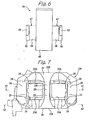
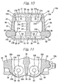
- the core 44 is provided in a mold 55 indicated by a two-dot chain line in Fig. 4 . Then, for example, an aluminum alloy in molten state is charged into a cavity 56 formed by the mold 55 and the core 44. In the cavity 56, the pad-mounting space forming portions 46 are fully spaced apart from each other. After charging, the mold is disassembled, and the core 44 is removed. As a result, a caliper body casting 16A shown in Figs. 7 to 15 is obtained.
- the outer-side cylinder portion 20 and the inner-side cylinder portion 21 facing each other are formed by means of the mold 55 and the two pad-mounting space forming portions 46 of the core 44.
- the three outer-side torque bearing portions 23 respectively project from the outer-side cylinder portion 20 towards the inner side of the disc while being spaced from each other in a direction of rotation of the disc.
- the three inner-side torque bearing portions 24 respectively project from the inner-side cylinder portion 21 towards the outer side of the disc while being spaced from each other in a direction of rotation of the disc.
- the three disc pass portions 26 are formed, each of which connects outer sides (in a radial direction of the disc) of the outer-side torque bearing portion 23 and the inner-side torque bearing portion 24 arranged in an axial direction of the disc.
- the casting 16A also includes three interpositions 58 each connecting, on an inner side of the disc pass portion 26 (as viewed in a radial direction of the disc), the outer-side torque bearing portion 23 and the inner-side torque bearing portion 24 arranged in an axial direction of the disc, and thus the two pad-mounting spaces 28 are formed at two positions between the outer-side cylinder portion 20 and the inner-side cylinder portion 21. As indicated in Fig.
- the disc pass portion 26 and the interposition 58 corresponding to each other in terms of a position in a direction of rotation of the disc are formed as one piece in a radial direction of the disc.
- a surface 58A of the interposition 58 on an inner side thereof in a radial direction of the disc, and a surface 23A of the outer-side torque bearing portion 23 and a surface 24A of the inner-side torque bearing portion 24, are connected without being stepped.
- the two pad-mounting spaces 28 are formed by means of two pad-mounting space forming portions 46 of the core 44.
- the outer-side cylinder portion 20 of the casting 16A of the caliper body 16 includes prepared holes 31A, which are formed by means of the prepared hole forming portions 47 projecting from the pad-mounting space forming portions 46 of the core 44.
- two prepared holes 31A are formed, each of which is formed between the adjacent outer-side torque bearing portions 23 of the outer-side cylinder portion 20.
- Each of the prepared holes 31A is formed in a surface 20A facing the inner-side cylinder portion 21, so as to have a predetermined depth.
- an inner-diameter prepared hole portion 32A of the prepared hole 31A having a cylindrical surface is formed by means of the inner-diameter prepared hole forming portion 49 of the core 44.
- an inmost recess portion 60 of the prepared hole 31A which has a larger diameter than the inner-diameter prepared hole portion 32A and also has a larger diameter than the inner-diameter portion 32 of the bore 31 after machining, is formed at an end of the inner-diameter prepared hole portion 32A on a side of a bottom portion 61 in a coaxial relationship with the inner-diameter prepared hole portion 32A.
- a bottom surface 59 forming the inmost recess portion 60 of each prepared hole 31A includes a projection 64 slightly projecting therefrom in an axial direction.
- the projection 64 is formed by means of the projection forming portion 53 of the core 44 during casting.
- a recess 63 is formed at the inmost recess portion 60 (i.e., the bottom portion 61 of the prepared hole 31A) on the exit side of the disc during braking when the vehicle travels in a forward direction.
- the recess 63 is located on a side opposite to the communication passage 62 relative to the inmost recess portion 60.
- the recess 63 is formed by means of the recess forming portion 52 of the core 44, and has a non-circular form. Specifically, the recess 63 has a substantially tapered triangular form extending outwardly in a radial direction of the prepared hole 31A while being inclined relative to the radial direction of the prepared hole 31A. The recess 63 extends from the inmost recess portion 60 outwardly in a radial direction of the disc.
- a distal end of the recess is located outwardly from a region occupied by the corresponding inmost recess portion as viewed in a direction of rotation of the disc, while being located radially outwardly from the center axis of the corresponding bore as viewed in a radial direction of the disc.
- a proximal end of the recess 63 which is located on a side of the inmost recess portion 60, extends to a position corresponding to the center axis of the prepared hole 31A or a position located inwardly from the center axis of the prepared hole 31A as viewed in the radial direction of the disc 12.
- the proximal end of the recess extends, outwardly in a radial direction of the disc along the circumference of the inmost recess portion, from a position corresponding to the center axis of the corresponding bore or a position located inwardly from the center axis of the corresponding bore as viewed in a radial direction of the disc.
- the inner-side cylinder portion 21 of the casting 16A of the caliper body 16 includes prepared holes 31A, which are formed by means of the prepared hole forming portions 47 projecting from the pad-mounting space forming portions 46 of the core 44. Specifically, two prepared holes 31A are formed, each of which is formed between the adjacent inner-side torque bearing portions 24 of the inner-side cylinder portion 21. Each of the prepared holes 31A is formed in a surface 21A facing the outer-side cylinder portion 20 so as to have a predetermined depth.
- the inner-diameter prepared hole portion 32A of the prepared hole 31A having a cylindrical surface is formed by means of the inner-diameter prepared hole forming portion 49 of the core 44.
- the inmost recess forming portion 50 of the core 44 the inmost recess portion 60, which has a larger diameter than the inner-diameter prepared hole portion 32A and also has a larger diameter than the inner-diameter portion 32 of the bore 31 after machining, is formed at an end of the inner-diameter prepared hole portion 32A on a side of the bottom portion 61 in a coaxial relationship with the inner-diameter prepared hole portion 32A.
- the bottom surface 59 forming the inmost recess portion 60 of each prepared hole 31A includes the projection 64 slightly projecting therefrom in an axial direction.
- the projection 64 is formed by means of the projection forming portion 53 of the core 44 during casting.
- proximately opposed portions of the inmost recess portions 60 disposed adjacent to each other in the direction of rotation of the disc are communicated with each other through the communication passage 62, which is formed by means of the communication passage forming portion 51 of the core 44 during casting.
- the recess forming portion 52 of the core 44 the recess 63 is formed at the inmost recess portion 60 on the exit side of the disc during braking when the vehicle travels in a forward direction.
- the recess 63 is located on a side opposite to the communication passage 62 relative to the inmost recess portion 60.
- the recess 63 has a non-circular form.
- the recess 63 has a substantially tapered triangular form extending from the inmost recess portion 60 outwardly in a radial direction of the prepared hole 31A.
- the proximal end of the recess 63 which is located on a side of the inmost recess portion 60, extends to a position corresponding to the center axis of the prepared hole 31A or a position located inwardly from the center axis of the prepared hole 31A as viewed in the radial direction of the disc 12.
- the recess 63 of the outer-side cylinder portion 20 and the recess 63 of the inner-side cylinder portion 21 correspond to each other in terms of a position in the direction of rotation and in the radial direction of the disc.
- prepared holes 31A which are machined into the bores 31, are arranged at a plurality (two in this embodiment) of positions in a spaced relationship in the direction of rotation of the disc 12.
- the inner-side torque bearing portion 24, the outer-side torque bearing portion 23, the disc pass portion 26 and the interposition 58 are formed as a one-piece member by casting between the prepared holes 31A adjacent to each other in the direction of rotation of the disc.
- the recess 63 is formed at a position corresponding to the top of the uppermost prepared hole 31A (the prepared hole 31A located on the exit side of the disc during braking when the vehicle travels in a forward direction) when the caliper body is mounted on the vehicle body.
- the number of the pad-mounting spaces 28 and the number of the prepared holes 31A facing the pad-mounting spaces 28 are increased according to the number of bores 31, and the communication passage 62 is provided at each of the positions between the prepared holes 31A arranged in the direction of rotation of the disc.
- the inner-side torque bearing portion 24, the outer-side torque bearing portion 23, the disc pass portion 26 and the interposition 58 which are formed into one piece by casting, are also provided at each of the positions between the prepared holes 31A arranged in a direction of rotation of the disc.
- the recess 63 is formed at the inmost recess portion 60 on a side opposite to the communication passage 62, the inmost recess portion 60 being located most closely to the exit side of the disc during braking when the vehicle travels in a forward direction and also located at an uppermost position when the caliper body is mounted.
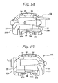
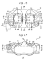
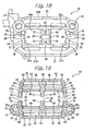
- the casting 16A is machined in a manner such as mentioned below, to thereby obtain the caliper body 16 shown in Figs. 16 to 26 .
- An outer surface 20B of the outer-side cylinder portion 20 on a side opposite to the disc 12 and an outer surface 21B of the inner-side cylinder portion 21 on a side opposite to the disc 12 are clamped by means of a machining apparatus.
- the interposition 58 formed on an inner side of the disc pass portion 26 in a radial direction of the disc 12 makes an intermediate portion between the outer-side torque bearing portion 23 and the inner-side torque bearing portion 24 have the same wall thickness as the outer-side torque bearing portion 23 and the inner-side torque bearing portion 24 in a radial direction of the disc 12.
- outer-side torque bearing portion 23, the inner-side torque bearing portion 24, the disc pass portion 26 and the interposition 58 are provided between the prepared holes 31A adjacent to each other in a direction of rotation of the disc, in addition to those provided on opposite ends of the outer-side cylinder portion 20 and the inner-side cylinder portion 21 in a direction of rotation of the disc. Therefore, deformation of the casting 16A due to application of clamping force can be prevented.
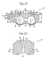
- a tool is inserted from each pad-mounting space 28 between the outer-side cylinder portion 20 and the inner-side cylinder portion 21 into the casting 16A clamped by the machining apparatus. Then, as shown in Figs. 19 and 21 , a cutting operation is conducted with respect to only the inner-diameter prepared hole portion 32A of the prepared hole 31A formed in each of the outer-side cylinder portion 20 and the inner-side cylinder portion 21 and facing the pad-mounting space 28, and the inner-diameter prepared hole portion 32A is formed into the inner-diameter portion 32 by boring (see the inner-diameter prepared hole portion 32A before boring and the inner-diameter portion 32 obtained after boring shown in Fig. 26 ).
- each of the bores 31 formed comprises the inner-diameter portion 32 and the seal grooves 66 and 67, which are formed by machining, and the inmost recess portion 60 which is unmachined after casting.
- the piston 17 is fitted into the inner-diameter portion 32 of each bore 31, with seal rings (not shown) being fittingly disposed in the seal grooves 66 and 67.
- each of the bores 31 is formed by machining from a portion on a side of the pad-mounting space 28 between the inner-side cylinder portion 21 and the outer-side cylinder portion 20.
- the bottom portions 61 of all the bores 31 are maintained in a closed state obtained by casting.
- the projection 64 of the inmost recess portion 60 enables the piston 17 and the bottom surface 59 to be always spaced apart from each other, even when the piston 17 abuts against the projection 64.
- a tool is inserted from each pad-mounting space 28 between the outer-side cylinder portion 20 and the inner-side cylinder portion 21 and the surfaces of the outer-side torque bearing portion 23 and the surfaces of the inner-side torque bearing portion 24 facing the pad-mounting space 28 are cut by milling, to thereby form outer-side torque bearing surfaces 70 and inner-side torque bearing surfaces 71 shown in Figs. 16 , 18 , 19 and 21 .
- the outer-side torque bearing surfaces 70 and inner-side torque bearing surfaces 71 are adapted to abut against the end surfaces of the pads 33 in a direction of rotation of the disc 12, to thereby receive a torque from the pads 33.
- the mounting bolt openings 37 shown in Figs. 16 and 18 to 20 for insertion of mounting bolts into the mount portion 14 of the front fork 13 are formed by boring in the outer-side cylinder portion 20 at two positions spaced apart from each other in a direction of rotation of the disc 12.
- the mounting bolt openings 37 orthogonally intersect an axial direction of the disc and extend through the outer-side cylinder portion 20 in parallel to each other.
- the pad pin holes 41 extending in an axial direction of the disc 12 are also formed by boring.
- a linear passage opening 75 is formed by boring from an external surface of the outer-side cylinder portion 20 as viewed in a direction of rotation of the disc 12 so as to extend towards the top of the recess 63 of the outer-side cylinder portion 20.
- the bleeder mounting opening 40 is threaded.
- the passage opening 75 is formed by cutting from the external surface of a portion of the outer-side cylinder portion 20 that is located at an upper position when the caliper body is mounted on a vehicle body, and is communicated with the recess 63.
- a linear communication opening 76 with the pipe mount opening 38 for mounting a brake pipe from a master cylinder being formed at an open end portion thereof, is formed by boring from an external surface of the outer-side cylinder portion 20 as viewed in an axial direction of the disc 12 so as to extend towards an intermediate position in the caliper body 16.
- An intermediate part of the communication opening 76 intersects the passage opening 75 having the bleeder mounting opening 40.
- the pipe mount opening 38 is threaded.
- a connection opening (passage opening) 77 is formed by boring from an external surface of the inner-side cylinder portion 21 as viewed in an axial direction of the disc 12 so as to extend towards the intermediate position in the caliper body 16.
- connection opening 77 extends through the recess 63 of the inner-side cylinder portion 21 and intersects the communication opening 76. To close an open end of the connection opening 77 exposed at the external surface of the inner-side cylinder portion 21, a ball is struck into the open end of the connection opening 77 during assembly.
- the adjacent inmost recess portions 60 that is, the bores 31, of the outer-side cylinder portion 20 arranged in a direction of rotation of the disc 12 are communicated with each other through the communication passage 62.
- the adjacent inmost recess portions 60 that is, the bores 31, of the inner-side cylinder portion 21 are also communicated with each other through the communication passage 62.
- the inmost recess portion 60 (that is, the bore 31) having the recess 63 in the outer-side cylinder portion 20 is communicated through this recess 63, the passage opening 75, the communication opening 76 and the connection opening 77 with the inmost recess portion 60 (that is, the bore 31) having the recess 63 in the inner-side cylinder portion 21.
- all the bores 31, i.e., the bores 31 arranged in a direction of rotation of the disc 12, and the bores 31 disposed in a face-to-face relationship in an axial direction of the disc 12 with the bores 31 arranged in the direction of notation of the disc 12, are communicated with each other, and disposed in a single brake fluid flow passage.
- all the bores 31 are communicates with the pipe mount opening 38 formed at the open end portion of the communication opening 76. Therefore, brake fluid is introduced into the bores 31 through a brake pipe which is connected to the communication opening 76 during assembly. Further, all the bores 31 are communicated with the bleeder mounting opening 40 formed at the open end portion of the passage opening 75. Therefore, release of air is conducted through the bleeder plug 39, which is connected to the bleeder mounting opening 40 during assembly.
- Each disc pass portion 26 connects outer sides (as viewed in a radial direction of the disc) of the outer-side torque bearing portion 23 and the inner-side torque bearing portion 24, and has a smaller wall-thickness than the outer-side torque bearing portion 23 and the inner-side torque bearing portion 24.
- machining operations is not limited to the above embodiment and may be appropriately changed.
- the prepared hole 31A for the bore 31 into which the piston 17 is slidably fitted and the recess 63 extending from the bottom portion 61 of the prepared hole 31A outwardly in a radial direction of the prepared hole 31A are formed by means of the core 44 during casting. Therefore, an open end of the recess 63 which connects to the bore 31 can be formed with high precision.
- the linear passage opening 75 and the connection opening 77 are formed by cutting from an exterior surface of the caliper body 16 so as to extend to the recesses 63 which are formed with high precision relative to the bores 31.
- the passage opening 75 and the connection opening 77 are not required to form the passage opening 75 and the connection opening 77 with high machining accuracy, resulting in ease of forming operations and high production efficiency. Further, it is unnecessary to form the passage opening 75 and the connection opening 77 while avoiding interference with an opening for mounting a separate bottom portion of the bore. Therefore, the positions of the passage opening 75 and the connection opening 77 can be determined with a high degree of freedom of design.
- the adjacent bores 31 are communicated with each other through the communication passage 62 which is formed during casting.
- the recess 63 is formed at a position corresponding to the top of the uppermost bore 31 when the caliper body is mounted on a vehicle body.
- the linear passage opening 75 for communication with the recess 63 is formed by cutting from an external surface of the caliper body 16 at a position on an upper side when the caliper body is mounted on a vehicle body. Therefore, release of air can be satisfactorily conducted through the communication passage 62, the recess 63 and the passage opening 75.
- the plurality of bores 31 formed in a spaced relationship in a direction of rotation of the disc are communicated with each other through the communication passage 62, the recess 63 and the passage opening 75. Further, a part of the connection passage 80 for communication between the bores 31 disposed on opposite sides in an axial direction of the disc 12 is formed by the communication opening 76 which is formed by cutting from an exterior surface so as to intersect the passage opening 75. Therefore, it is possible to reduce the number of openings for communication between all the bores 31 arranged in a direction of rotation of the disc and arranged in an axial direction of the disc.
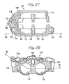
- Figs. 27 and 28 show a second embodiment of the present invention.
- elements corresponding to those in the first embodiment are designated by the corresponding reference numerals prefixed with 1.
- the constructions and effects of those elements are the same as those in the first embodiment, unless otherwise described.
- a pipe mount opening 138 is formed between two bores 131 of an outer-side cylinder portion 120.
- a portion between the mounting bolt opening 37 and an adjacent exterior surface of the outer-side cylinder portion 20 is required to have a sufficiently large wall thickness for accommodating the pipe mount opening 38 and the communication opening 76 extending therefrom.
- the pipe mount opening 138 is formed between the two bores 131, there is no need to provide such a portion having a large wall thickness. This achieves a reduction in weight of the caliper body.
- the recesses 163 on opposite sides of the caliper body 116 are communicated with each other through two passage openings 175 and 175a intersecting each other, and also communicated with a bleeder mounting opening 140.
- An outer end of the passage opening 175a is to be closed in the same manner as in the first embodiment.
- the same effects as those of the first embodiment can be obtained by using two linear passage openings, and therefore an operation for forming passage openings becomes easy.
- the recesses 163 increases the freedom of design regarding the location of passage openings, and enable the linear passage opening 175a to pass through the wall between a pad-mounting space 128 and the mounting bolt opening 137 disposed adjacent to the recess 163.
- a proximal end of the recess 163 extends along the circumference of the corresponding bore 131 to a position that is located inwardly from the center axis of the bore as viewed in a radial direction of the disc.
- This arrangement has the same effect as the first embodiment. That is, when the caliper body 116 is mounted in a vertical position with the recess 163 being located at the top of the corresponding bore 131, it is possible to more effectively prevent air from being trapped in the uppermost portion of the circumferential wall surface of the bore.
- the position to which the proximal end of the recess 163 extends along the circumference of the bore 131 may be defined in a different way as well.
- the position may be located on a gravity line that is drawn from the center axis of the bore in a direction parallel to the direction of gravity when the caliper body 116 is mounted on a vehicle, wherein the intersection of the gravity line and the circumference of the bore near an inner end of the linear passage opening 175a communicating with the recess 163 is closer to the center of the disc than an intersection of a radius line drawn from the center of the bore to the inner end of the linear passage opening 175a and the circumference.
- the caliper is mounted on the vehicle substantially vertically as shown schematically in Figs. 1 and 2 .
- the position may also be located on the same side of the gravity line as the center of the disc.
Landscapes
- Engineering & Computer Science (AREA)
- General Engineering & Computer Science (AREA)
- Mechanical Engineering (AREA)
- Braking Arrangements (AREA)
Claims (20)
- Scheibenbremse, umfassend:ein Paar Beläge (33), die an gegenüberliegenden Seiten einer Scheibe (12) anordenbar sind;einen Bremssattel (11), der derart anordenbar ist, um sich über die Scheibe (12) zu erstrecken, wobei der Bremssattel (11) ausgebildet ist, um an einem Fahrzeug angeordnet zu werden; undKolben (17) umfassend zumindest einen Kolben (17), der gleitbar in jeder Seite des Bremssattels (11) gehalten wird, um an jeder Seite der Scheibe (12) angeordnet zu sein, wobei jeder Kolben (17) an einer Seite des entsprechenden Belags (33) gegenüber der Seite von jedem Belag (33) angeordnet ist, der ausgebildet ist, um die Scheibe (12) zu kontaktieren,wobei der Bremssattel (11), umfasst:maschinell hergestellte Bohrungen (31, 131) umfassend zumindest eine maschinell hergestellte Bohrung (31, 131) an jeder Seite der Scheibe (12), wobei jede maschinell hergestellte Bohrung (31, 131) aus einem vorbereiteten Loch (31A) maschinell hergestellt wird, in welches der zumindest eine Kolben (17) an jeder Seite gleitbar eingepasst wird,dadurch gekennzeichnet, dass der Bremssattel ferner umfasst:eine Ausnehmung (63, 133), die an jeder Seite der Scheibe (12) gemeinsam mit dem vorbereiteten Loch (31A) mittels eines Kerns (44) ausgebildet ist, wenn der Bremssattel (11) gegossen wird, sodass er sich von einem Abschnitt des Umfangs eines Bodenabschnitts (61) des vorbereiteten Lochs (31A) nach außen in einer Radialrichtung des vorbereiteten Lochs (31A) erstreckt;eine lineare Leitungsöffnung (75, 175), die durch Bohren ausgebildet wird, um sich von einer äußeren Oberfläche des Bremssattels (11) hin zu der Ausnehmung (63, 163) an einer Seite der Scheibe (12) zu erstrecken; undeine weitere lineare Leitungsöffnung (77, 175a) in Verbindung mit der linearen Leitungsöffnung (75, 175), wobei die weitere lineare Leitungsöffnung (77, 175a) durch Bohren ausgebildet wird, um sich von der äußeren Oberfläche des Bremssattels (11) hin zu der Ausnehmung (63, 163) an der anderen Seite der Scheibe (12) zu erstrecken,wobei die Bohrungen (31, 131) an den jeweiligen Seiten der Scheiben (12) in Verbindung miteinander über die lineare Leitungsöffnung (75, 175) und die weitere lineare Leitungsöffnung (77, 175a) stehen.
- Scheibenbremse nach Anspruch 1, bei der
der Bremssattel (11) die Vielzahl an Bohrungen (31, 131) umfasst, die in einer beabstandeten Beziehung in einer Richtung der Drehung (R) der Scheibe (12) angeordnet sind und eine Verbindungsleitung (62) zur Verbindung zwischen jedem Paar der angrenzenden Bohrungen (31, 131) umfasst, wobei die Verbindungsleitungen (62) gemeinsam mit der Vielzahl an vorbereiteten Löchern (31A) in dem Bremssattel (11) mittels des Kerns (44) ausgebildet werden, wenn der Bremssattel (11) gegossen wird;
wobei die Ausnehmung (63, 163) an jeder Seite an einer Position ausgebildet wird, die der Spitze des obersten vorbereiteten Lochs (31A) von der Vielzahl an vorbereiteten Löchern (31A) entspricht, wenn der Bremssattel (11) an dem Fahrzeug angeordnet wird; und
wobei die Leitungsöffnung (75, 175) und die weitere Leitungsöffnung (77, 175a) in Verbindung mit den Ausnehmungen (63, 163) ausgebildet werden, um sich von der äußeren Oberfläche eines Abschnitts des Bremssattels (11) zu erstrecken, die an einer oberen Position angeordnet ist, wenn der Bremssattel an dem Fahrzeug angeordnet wird. - Scheibenbremse nach Anspruch 1, bei der der Bremssattel (11) eine lineare Kommunikationsöffnung (76) umfasst, wobei die lineare Kommunikationsöffnung (76) ausgebildet ist, um sich von der externen Oberfläche des Bremssattels (11) zu erstrecken und um die Leitungsöffnung (75) und die weitere Leitungsöffnung (77) zu schneiden, um die Leitungsöffnungen (75, 77) miteinander zu verbinden.
- Scheibenbremse nach Anspruch 1, bei der der Bremssattel einen innenseitigen Zylinderabschnitt (21, 121) und einen außenseitigen Zylinderabschnitt (20, 120) umfasst, welche jeweils die Bohrung (31, 131) aufweisen, in welche der Kolben gleitbar eingepasst wird, wobei der innenseitige und der außenseitige Zylinderabschnitt als einstückiges Element durch Gießen ausgebildet werden; und
wobei die Bohrungen durch Bearbeiten von all den vorbereiteten Löchern (31A) von Abschnitten davon an einer Seite eines Raums (28) zwischen dem innenseitigen Zylinderabschnitt (21, 121) und dem außenseitigen Zylinderabschnitt (20, 120) in Richtung der Bodenabschnitte (61) der vorbereiteten Löcher (31) ausgebildet werden, um dadurch einen verschlossenen Zustand der Bodenabschnitte (61) von all den vorbereiteten Löchern (31A), die durch Gießen erhalten werden, aufrechtzuerhalten. - Scheibenbremse nach Anspruch 4, bei der:die vorbereiteten Löcher (31A) jeweils einen inneren vorbereiten Lochabschnitt (32A) und einen innersten Ausnehmungsabschnitt (60) umfassen, der einen größeren Durchmesser als der des inneren vorbereiteten Lochabschnitts (32A) aufweist, undwobei der innere vorbereitete Lochabschnitt (32A), die innersten Ausnehmungsabschnitte (60) und die Ausnehmungen (63, 133), die sich von den Abschnitten der Umfänge der innersten Ausnehmungsabschnitte (60) nach außen in einer Radialrichtung davon erstrecken, mittels des Kerns (44) ausgebildet werden, wenn der Bremssattel (11) gegossen wird; undwobei die Bohrungen (31, 131) durch Bearbeiten des inneren vorbereiteten Lochabschnitts (32A) des vorbereiteten Lochs (31A) von Abschnitten davon an einer Seite des Raums (28) zwischen dem innenseitigen Zylinderabschnitt (21, 121) und dem außenseitigen Zylinderabschnitt (20, 120) geformt werden.
- Scheibenbremse nach Anspruch 1, bei der jede der maschinell hergestellten Bohrungen (31, 131) einen maschinell hergestellten inneren Durchmesserabschnitt (32) und einen innersten Ausnehmungsabschnitt (60), der an einem Bodenabschnitt (61) der Bohrung des innersten Ausnehmungsabschnitts (60), der einen größeren Durchmesser als der des inneren Durchmesserabschnitts der Bohrung aufweist, angeordnet ist, aufweist, und
wobei die innersten Ausnehmungsabschnitte (60) und die Ausnehmung (63, 163), die mittels des Kerns (44) ausgebildet werden, wenn der Bremssattel (11) gegossen wird, unbearbeitet bleiben. - Scheibenbremse nach Anspruch 1, bei der:der Bremssattel (11) die Vielzahl an maschinell hergestellten Bohrungen (31, 131) umfasst, die an den jeweiligen Seiten des Bremssattels ausgebildet sind, um in einer beabstandeten Beziehung in einer Rotationsrichtung der Scheibe (12), über die sich der Bremssattel erstreckt, wenn der Bremssattel an dem Fahrzeug angeordnet ist, angeordnet zu werden; wobei die Bohrungen (31, 131) jeweils einen innersten Ausnehmungsabschnitt (60) aufweisen, der an einem Bodenabschnitt (61) der Bohrung (31, 131) angeordnet ist, wobei der innerste Ausnehmungsabschnitt (60) einen größeren Durchmesser als der des inneren Durchmesserabschnitts (32A) der Bohrung aufweist; undwobei der innerste Ausnehmungsabschnitt (60), die Ausnehmung (63, 163), die sich von einem Abschnitt des Umfangs des innersten Ausnehmungsabschnitts nach außen in einer Radialrichtung davon erstreckt, sowie eine Verbindungsleitung (62) zur Verbindung zwischen den innersten Ausnehmungsabschnitten der angrenzenden Bohrungen, mittels des Kerns (44) ausgebildet werden, wenn der Bremssattel (11) gegossen wird.
- Scheibenbremse nach einem der Ansprüche 1 bis 4, bei der die Leitungsöffnung (75, 175) und die weitere Leitungsöffnung (77, 175a) in Verbindung mit einem distalen Ende der Ausnehmung (63, 163) sind, die sich von einer Bohrung nach außen in der Radialrichtung davon erstreckt.
- Scheibenbremse nach einem der Ansprüche 5 bis 7, bei der die Leitungsöffnung (75, 175) und die weitere Leitungsöffnung (77, 175a) in Verbindung mit einem distalen Ende der Ausnehmung (63, 163) sind, die sich von dem innersten Ausnehmungsabschnitt (60) der einen Bohrung (31, 131) nach außen in der Radialrichtung davon erstreckt.
- Scheibenbremse nach einem der Ansprüche 1 bis 4, bei der ein proximales Ende der Ausnehmung (63, 163) sich nach außen in einer Richtung erstreckt, die einer Radialrichtung der Scheibe entspricht, über die sich der Bremssattel (11) erstreckt, wenn der Bremssattel an einem Fahrzeug angeordnet wird, von einem Abschnitt des Umfangs des Bodenabschnitts (61), der an einer Position angeordnet ist, die der zentralen Achse der einen Bohrung (31, 131) oder einer in Radialrichtung relativen Position zu einer zentralen Achse der einen Bohrung (31, 131) entspricht, wenn in der Radialrichtung der Scheibe (12) betrachtet.
- Scheibenbremse nach einem der Ansprüche 5 bis 7, bei der ein proximales Ende der Ausnehmung (63, 163) sich nach außen in einer Richtung erstreckt, die einer Radialrichtung der Scheibe (12) entspricht, über welche sich der Bremssattel (11) erstreckt, wenn der Bremssattel an einem Fahrzeug angeordnet wird, von dem Abschnitt des Umfangs des innersten Ausnehmungsabschnitts (60), der an einer Position angeordnet ist, die der zentralen Achse der einen Bohrung (31, 131) entspricht oder einer Position radial einwärts relativ zu der zentralen Achse der einen Bohrung (31, 131), wenn in der Radialrichtung der Scheibe (12) betrachtet.
- Scheibenbremse nach einem der Ansprüche 1 bis 7, bei der eine Entlüftungsanbringungsöffnung (40, 140) zum Anbringen eines Entlüftungsventils (39) zum Auslassen von Luft an dem Ende der Leitungsöffnung (75, 175) gegenüber des Endes, das sich zu der Ausnehmung (63, 163) erstreckt, ausgebildet ist.
- Scheibenbremse nach einem der Ansprüche 1 bis 7, bei der die Leitungsöffnung (175) oder eine weitere Leitungsöffnung (175a) sich zwischen einer Anbringbolzenöffnung (137), die sich in einer Richtung erstreckt, die einer Radialrichtung der Scheibe (12) entspricht, über welche sich der Bremssattel (11) erstreckt, wenn der Bremssattel an einem Fahrzeug angeordnet wird, und einem Belaganbringraum (128) erstreckt.
- Scheibenbremse nach einem der Ansprüche 1 bis 4, bei der ein distales Ende der Ausnehmung (63, 163) von einem Bereich ausgehend nach außen gerichtet ist, der von dem Bodenabschnitt (61) der einen Bohrung (31, 131) belegt ist, wenn in einer Richtung betrachtet, die der Rotationsrichtung der Scheibe (12) entspricht, über welche sich der Bremssattel (12) erstreckt, wenn der Bremssattel an einem Fahrzeug angeordnet wird, und das distale Ende außerhalb relativ zu dem Ende der Bohrung (31, 131) in der Rotationsrichtung der Scheibe (12) angeordnet ist.
- Scheibenbremse nach einem der Ansprüche 5 bis 7, bei der ein distales Ende der Ausnehmung (63, 163) nach außen von einem Bereich, der von dem innersten Ausnehmungsabschnitt (60) der einen Bohrung (31, 131) belegt ist, gerichtet ist, wenn in einer Richtung betrachtet, die einer Rotationsrichtung der Scheibe (12) entspricht, über welche sich der Bremssattel (12) erstreckt, wenn der Bremssattel an einem Fahrzeug angeordnet wird, und das distale Ende außerhalb relativ zu dem Ende des innersten Ausnehmungsabschnitts (60) in der Rotationsrichtung der Scheibe (12) angeordnet ist.
- Scheibenbremse nach einem der Ansprüche 1 bis 7, bei der ein proximales Ende der Ausnehmung (63, 163) sich nach außen in einer Richtung erstreckt, die einer Radialrichtung der Scheibe (12) entspricht, über welche sich der Bremssattel erstreckt, wenn er an einem Fahrzeug angeordnet wird, entlang des Umfanges des Bodenabschnitts (61), von einer Position, die auf einer Schwerkraftlinie liegt, die von der zentralen Achse der einen Bohrung (31, 131) in einer Richtung parallel zu der Schwerkraftrichtung gezogen wird, wenn der Bremssattel (11) auf einem Fahrzeug angeordnet ist, wobei der Schnittpunkt der Schwerkraftlinie und des Umfangs der einen Bohrung (31, 131) in der Nähe eines inneren Endes der linearen Leitungsöffnung (75, 175), die in Verbindung mit der Ausnehmung (63, 163) steht, näher zu dem Zentrum der Scheibe (12) ist als ein Schnittpunkt einer Radiuslinie, die von dem Zentrum der einen Bohrung (31, 131) hin zu dem inneren Ende der linearen Leitungsöffnung (75, 175) und dem Umfang oder auf die selbe Seite wie die Linie als dem Zentrum der Scheibe (12) gezogen wird.
- Ein gegossener Bremssattel (16, 116), der hergestellt wird, um einen Bremssattel für eine Scheibenbremse (1) auszubilden, umfassend:vorbereitete Löcher (31A) umfassend zumindest ein vorbereitetes Loch (31A), das an jeder Seite des Raums (28) ausgebildet ist, in welchen eine Scheibe (12) eingeführt wird, wenn der gegossene Bremssattel (16, 116) an einem Fahrzeug angeordnet wird, wobei zumindest ein vorbereitetes Loch (31A) ausgebildet ist, um hergestellt zu werden, um zumindest eine Bohrung (31, 131) auszubilden, in welche ein Kolben (17) gleitbar eingepasst werden kann;eine Ausnehmung (63, 163), die an jeder Seite von dem gegossenen Bremssattel (16, 116) gemeinsam mit einem vorbereiteten Loch (31A) mittels eines Kerns ausgebildet wird, wenn der Bremssattel gegossen wird, wobei die Ausnehmung (63, 163) sich von einem Abschnitt des Umfangs eines Bodenabschnitts des vorbereiteten Lochs (31A) nach außen in einer Radialrichtung des vorbereiteten Lochs erstreckt.
- Gegossener Bremssattel nach Anspruch 17, bei dem
das mindestens eine vorbereitete Loch (31A) maschinell hergestellt wird, um zumindest eine Bohrung (31, 131) auszubilden, in welche ein Kolben (17) gleitbar eingepasst werden kann;
wobei eine lineare Leitungsöffnung (75, 175) ausgebildet wird, indem gebohrt wird, um sich von einer externen Oberfläche des gegossenen Bremssattels (16, 116) hin zu der Ausnehmung (63, 163), an einer Seite des Raums (28) zu erstrecken, und
wobei eine weitere Leitungsöffnung (75, 175a) durch Bohren ausgebildet wird, um mit der Leitungsöffnung (75, 175) in Verbindung zu stehen und um sich von der äußeren Oberfläche des Bremssattels (16, 116) hin zu der Ausnehmung (63, 163) zu erstrecken, die an der anderen Seite des Raums (28) angeordnet ist. - Verfahren zur Herstellung einer Scheibenbremse, umfassend die Schritte:Gießen eines Bremssattels (16, 116) in einer Form umfassend einen Kern, um einen gegossenen Bremssattel auszubilden, umfassend zumindest ein vorbereitetes Loch (31A) und eine Ausnehmung (63, 163), die sich von einem Abschnitt des Umfangs eines Bodenabschnitts des vorbereiteten Lochs (31A) nach außen in einer Radialrichtung des vorbereiteten Lochs an jeder Seite eines Raums (28) erstreckt, in welchen die Scheibe (12) eingeführt wird, wenn der Bremssattel (16, 116) an einem Fahrzeug angeordnet wird;Maschinelles Bearbeiten von jedem vorbereiteten Loch (31A), um eine Bohrung (31, 131) auszubilden, in welche ein Kolben (17) gleitbar eingepasst werden kann; undBohren von zumindest zwei linearen Leitungsöffnungen (75, 77; 175, 175a), die in dem gegossenen Bremssattel miteinander verbindbar sind, um sich von einer externen Oberfläche des Bremssattels (16, 116) zu jeder Ausnehmung (63, 163) hin zu erstrecken.
- Verfahren zur Herstellung einer Scheibenbremse nach Anspruch 19, bei der die Ausnehmung (63, 163) mittels des Kerns ausgebildet wird, sodass ein distales Ende der Ausnehmung (63, 163) von einem Bereich ausgehend nach außen gerichtet ist, der von einem Bodenabschnitt (61) der einen Bohrung (31, 131) belegt ist, wenn in einer Richtung betrachtet, die einer Rotationsrichtung der Scheibe (12) entspricht, über welche sich der Bremssattel erstrecken wird, wenn der Bremssattel an einem Fahrzeug angeordnet wird und das distale Ende ist außerhalb relativ zu dem distalen Ende der Bohrung (31, 131) in der Rotationsrichtung der Scheibe (12) angeordnet.
Applications Claiming Priority (2)
| Application Number | Priority Date | Filing Date | Title |
|---|---|---|---|
| JP2003399553A JP2005163809A (ja) | 2003-11-28 | 2003-11-28 | ディスクブレーキ |
| JP2003399553 | 2003-11-28 |
Publications (2)
| Publication Number | Publication Date |
|---|---|
| EP1548316A1 EP1548316A1 (de) | 2005-06-29 |
| EP1548316B1 true EP1548316B1 (de) | 2011-11-02 |
Family
ID=34544872
Family Applications (1)
| Application Number | Title | Priority Date | Filing Date |
|---|---|---|---|
| EP04028116A Expired - Lifetime EP1548316B1 (de) | 2003-11-28 | 2004-11-26 | Scheibenbremse. |
Country Status (3)
| Country | Link |
|---|---|
| US (2) | US20050115780A1 (de) |
| EP (1) | EP1548316B1 (de) |
| JP (1) | JP2005163809A (de) |
Families Citing this family (22)
| Publication number | Priority date | Publication date | Assignee | Title |
|---|---|---|---|---|
| US8672100B2 (en) * | 2005-02-07 | 2014-03-18 | Hitachi, Ltd. | Cylinder apparatus and disk brake |
| US7318502B2 (en) * | 2005-02-18 | 2008-01-15 | Costa Vincenzo F | Fluid passage layout for integrated motorcycle brake and suspension system |
| JP4828255B2 (ja) * | 2006-02-24 | 2011-11-30 | 日立オートモティブシステムズ株式会社 | ディスクブレーキ |
| US20070278049A1 (en) * | 2006-06-05 | 2007-12-06 | Akebono Brake Industry Co., Ltd. | Opposed piston type disc brake |
| ES2291123B1 (es) * | 2006-07-13 | 2008-12-16 | Fagor, S. Coop. | "macho y molde para la fabricacion de un caliper de freno por moldeo". |
| ITMI20061973A1 (it) * | 2006-10-13 | 2008-04-14 | Freni Brembo Spa | Pinza per freno a disco |
| KR20090068340A (ko) * | 2006-10-19 | 2009-06-26 | 누카베 코포레이션 | 디스크 브레이크의 브레이크 캘리퍼 |
| JP4832402B2 (ja) * | 2007-10-22 | 2011-12-07 | 日立オートモティブシステムズ株式会社 | ディスクブレーキおよびディスクブレーキの製造方法 |
| JP2009264506A (ja) * | 2008-04-25 | 2009-11-12 | Nissin Kogyo Co Ltd | 車両用ディスクブレーキ |
| JP5157816B2 (ja) | 2008-10-21 | 2013-03-06 | 株式会社アドヴィックス | ピストン対向型ディスクブレーキ |
| US8835017B2 (en) * | 2009-07-29 | 2014-09-16 | Yuan Deng Metals Industrial Co., Ltd. | Metal sheet member having high plastic bonding strength |
| JP5559503B2 (ja) * | 2009-09-30 | 2014-07-23 | 日立オートモティブシステムズ株式会社 | ディスクブレーキ |
| DE102009055420A1 (de) * | 2009-12-30 | 2011-07-07 | Robert Bosch GmbH, 70469 | Bremssattel für ein Fahrzeugbremssystem sowie Verfahren und Vorrichtung zum Herstellen eines Gussteils mit mindestens einer Führungsstruktur |
| JP2011163401A (ja) * | 2010-02-08 | 2011-08-25 | Nissin Kogyo Co Ltd | 車両用ディスクブレーキのキャリパボディ |
| WO2012025604A1 (de) * | 2010-08-26 | 2012-03-01 | Gustav Magenwirth Gmbh & Co. Kg | Geberarmatur und hydraulische scheibenbremse |
| DE102011052169A1 (de) * | 2011-07-27 | 2013-01-31 | Dr. Ing. H.C. F. Porsche Aktiengesellschaft | Bremssattel für eine Scheibenbremse eines Kraftfahrzeugs |
| US9874253B2 (en) * | 2011-09-20 | 2018-01-23 | Shimano, Inc. | Bicycle disk brake caliper with a fluid bleeding structure |
| JP6299650B2 (ja) * | 2015-03-31 | 2018-03-28 | 株式会社アドヴィックス | ディスクブレーキ装置 |
| USD785520S1 (en) * | 2015-07-20 | 2017-05-02 | Freni Brembo S.P.A. | Disc brake calliper |
| ITUA20162155A1 (it) * | 2016-03-31 | 2017-10-01 | Freni Brembo Spa | Corpo pinza di freno a disco |
| USD884567S1 (en) * | 2016-07-13 | 2020-05-19 | Nissin Kogyo Co., Ltd. | Caliper body of disk brake for vehicle |
| TWI889710B (zh) * | 2019-09-27 | 2025-07-11 | 日商日立安斯泰莫股份有限公司 | 車輛用碟式煞車之卡鉗本體 |
Family Cites Families (23)
| Publication number | Priority date | Publication date | Assignee | Title |
|---|---|---|---|---|
| DE2950660A1 (de) * | 1979-12-15 | 1981-07-02 | Alfred Teves Gmbh, 6000 Frankfurt | Bremssattel fuer eine teilbelag-scheibenbremse |
| JPS5942328A (ja) | 1982-09-03 | 1984-03-08 | Chisso Corp | 3−フルオロフエニルシクロヘキセン誘導体 |
| JP2762079B2 (ja) | 1987-04-01 | 1998-06-04 | 曙ブレーキ工業株式会社 | ブレーキ装置 |
| DE3906162A1 (de) * | 1989-02-28 | 1990-08-30 | Teves Gmbh Alfred | Festsattel-scheibenbremse mit asymmetrisch geteiltem bremsgehaeuse |
| JPH0775759B2 (ja) | 1991-04-30 | 1995-08-16 | 日信工業株式会社 | キャリパボディにおけるシリンダ孔間の連通孔形成方法 |
| JPH0596576A (ja) | 1991-10-04 | 1993-04-20 | Olympus Optical Co Ltd | 成形金型 |
| JPH08121510A (ja) | 1994-10-26 | 1996-05-14 | Nissin Kogyo Kk | 液圧式車両用ディスクブレーキのエア抜き構造 |
| DE69733495D1 (de) * | 1996-07-12 | 2005-07-14 | Kelsey Hayes Co | Bremssattel für scheibenbremse |
| JPH1030660A (ja) | 1996-07-16 | 1998-02-03 | Nissin Kogyo Kk | 液圧式車両用ディスクブレーキのピストン対向型キャリパボディ |
| JPH1182569A (ja) | 1997-09-12 | 1999-03-26 | Nissin Kogyo Kk | 車両用ディスクブレーキ |
| JP3568752B2 (ja) * | 1997-10-03 | 2004-09-22 | 住友電気工業株式会社 | マルチポット型ディスクブレーキ |
| JPH11117964A (ja) | 1997-10-17 | 1999-04-27 | Nissin Kogyo Kk | ブレーキキャリパ |
| JP2003502157A (ja) | 1997-10-20 | 2003-01-21 | ジェームズ バクレイ | チキソトロピー材料を用いた精密鋳造方法 |
| JP4108853B2 (ja) | 1998-12-17 | 2008-06-25 | 株式会社日立製作所 | ディスクブレーキ |
| EP1016804B1 (de) | 1998-12-31 | 2004-10-06 | Freni Brembo S.p.A. | Kühleinrichtung für eine Kraftfahrzeug-Scheibenbremse |
| JP2000283190A (ja) | 1999-03-26 | 2000-10-13 | Nissin Kogyo Co Ltd | 液圧式車両用ディスクブレーキのピストン対向型キャリパボディ |
| JP2001027267A (ja) * | 1999-07-15 | 2001-01-30 | Sumitomo Electric Ind Ltd | キャリパボディ |
| JP2001107994A (ja) | 1999-10-08 | 2001-04-17 | Akebono Brake Ind Co Ltd | 対向ピストン型ディスクブレーキ及びその製造方法 |
| JP4327338B2 (ja) | 2000-07-21 | 2009-09-09 | 三菱マテリアルテクノ株式会社 | 振動乾燥装置 |
| JP4061028B2 (ja) | 2001-01-17 | 2008-03-12 | 日信工業株式会社 | 車両用ディスクブレーキのキャリパボディ |
| JP4699645B2 (ja) | 2001-07-16 | 2011-06-15 | 昭和電工株式会社 | ブレーキキャリパーボディーおよびその製造方法 |
| AUPS066802A0 (en) | 2002-02-21 | 2002-03-14 | Pbr Australia Pty Ltd | Improved disc brake caliper |
| US8672100B2 (en) * | 2005-02-07 | 2014-03-18 | Hitachi, Ltd. | Cylinder apparatus and disk brake |
-
2003
- 2003-11-28 JP JP2003399553A patent/JP2005163809A/ja active Pending
-
2004
- 2004-11-26 EP EP04028116A patent/EP1548316B1/de not_active Expired - Lifetime
- 2004-11-26 US US10/996,393 patent/US20050115780A1/en not_active Abandoned
-
2007
- 2007-09-18 US US11/898,993 patent/US7797812B2/en not_active Expired - Fee Related
Also Published As
| Publication number | Publication date |
|---|---|
| EP1548316A1 (de) | 2005-06-29 |
| US20050115780A1 (en) | 2005-06-02 |
| US20080034572A1 (en) | 2008-02-14 |
| US7797812B2 (en) | 2010-09-21 |
| JP2005163809A (ja) | 2005-06-23 |
Similar Documents
| Publication | Publication Date | Title |
|---|---|---|
| EP1548316B1 (de) | Scheibenbremse. | |
| US5887684A (en) | Disk brake calliper | |
| US20100320038A1 (en) | Opposed-piston caliper body | |
| EP1462671A1 (de) | Einstückiger Schwimmsattel für eine Bremse | |
| JP4472317B2 (ja) | ディスクブレーキ | |
| US20050230197A1 (en) | One piece sliding brake caliper | |
| JP4943492B2 (ja) | ディスクブレーキ | |
| JP4339092B2 (ja) | キャリパボディの製造方法 | |
| EP3534028A1 (de) | Bremssattelgehäuse | |
| EP1515061A2 (de) | Radial montierte Scheibenbremse | |
| JP2010159820A (ja) | 車両用ディスクブレーキのキャリパボディ製造方法及びキャリパボディ | |
| EP4542077A1 (de) | Sattelscheibenbremse und fahrzeug damit | |
| US10487892B2 (en) | Brake caliper housing method of manufacture | |
| EP1904246B1 (de) | Scheibenbremssattel, verfahren zum giessen davon sowie giesskern | |
| WO2005123491A1 (en) | Disc brake caliper | |
| CN100575733C (zh) | 制动器壳体及其制造方法与包括该壳体的盘式制动器 | |
| JP2000337408A (ja) | 車両用ディスクブレーキのキャリパボディ | |
| JPH031625Y2 (de) | ||
| EP1744948B1 (de) | Scheibenbremsensattel | |
| JP2017080760A (ja) | 車両用ディスクブレーキのキャリパボディ製造方法及びキャリパボディ | |
| JP4250123B2 (ja) | 多ポット型車両用ディスクブレーキのキャリパボディの製造方法及びキャリパボディ | |
| HK1116240A (en) | Brake housing | |
| JPH09229109A (ja) | ディスクブレーキ | |
| AU2006214806A1 (en) | Brake housing |
Legal Events
| Date | Code | Title | Description |
|---|---|---|---|
| PUAI | Public reference made under article 153(3) epc to a published international application that has entered the european phase |
Free format text: ORIGINAL CODE: 0009012 |
|
| AK | Designated contracting states |
Kind code of ref document: A1 Designated state(s): AT BE BG CH CY CZ DE DK EE ES FI FR GB GR HU IE IS IT LI LU MC NL PL PT RO SE SI SK TR |
|
| AX | Request for extension of the european patent |
Extension state: AL HR LT LV MK YU |
|
| 17P | Request for examination filed |
Effective date: 20051215 |
|
| AKX | Designation fees paid |
Designated state(s): DE IT |
|
| 17Q | First examination report despatched |
Effective date: 20061012 |
|
| GRAP | Despatch of communication of intention to grant a patent |
Free format text: ORIGINAL CODE: EPIDOSNIGR1 |
|
| GRAS | Grant fee paid |
Free format text: ORIGINAL CODE: EPIDOSNIGR3 |
|
| GRAA | (expected) grant |
Free format text: ORIGINAL CODE: 0009210 |
|
| RTI1 | Title (correction) |
Free format text: DISC BRAKE. |
|
| AK | Designated contracting states |
Kind code of ref document: B1 Designated state(s): DE IT |
|
| REG | Reference to a national code |
Ref country code: DE Ref legal event code: R096 Ref document number: 602004035085 Country of ref document: DE Effective date: 20120105 |
|
| PLBE | No opposition filed within time limit |
Free format text: ORIGINAL CODE: 0009261 |
|
| STAA | Information on the status of an ep patent application or granted ep patent |
Free format text: STATUS: NO OPPOSITION FILED WITHIN TIME LIMIT |
|
| 26N | No opposition filed |
Effective date: 20120803 |
|
| REG | Reference to a national code |
Ref country code: DE Ref legal event code: R097 Ref document number: 602004035085 Country of ref document: DE Effective date: 20120803 |
|
| PGFP | Annual fee paid to national office [announced via postgrant information from national office to epo] |
Ref country code: DE Payment date: 20201110 Year of fee payment: 17 Ref country code: IT Payment date: 20201013 Year of fee payment: 17 |
|
| REG | Reference to a national code |
Ref country code: DE Ref legal event code: R119 Ref document number: 602004035085 Country of ref document: DE |
|
| PG25 | Lapsed in a contracting state [announced via postgrant information from national office to epo] |
Ref country code: DE Free format text: LAPSE BECAUSE OF NON-PAYMENT OF DUE FEES Effective date: 20220601 |
|
| PG25 | Lapsed in a contracting state [announced via postgrant information from national office to epo] |
Ref country code: IT Free format text: LAPSE BECAUSE OF NON-PAYMENT OF DUE FEES Effective date: 20211126 |