EP1544148B1 - Commande de frein d'ascenseur - Google Patents
Commande de frein d'ascenseur Download PDFInfo
- Publication number
- EP1544148B1 EP1544148B1 EP03703305A EP03703305A EP1544148B1 EP 1544148 B1 EP1544148 B1 EP 1544148B1 EP 03703305 A EP03703305 A EP 03703305A EP 03703305 A EP03703305 A EP 03703305A EP 1544148 B1 EP1544148 B1 EP 1544148B1
- Authority
- EP
- European Patent Office
- Prior art keywords
- section
- output
- electromotive force
- electromagnet
- brake
- Prior art date
- Legal status (The legal status is an assumption and is not a legal conclusion. Google has not performed a legal analysis and makes no representation as to the accuracy of the status listed.)
- Expired - Lifetime
Links
Images


Classifications
-
- B—PERFORMING OPERATIONS; TRANSPORTING
- B66—HOISTING; LIFTING; HAULING
- B66B—ELEVATORS; ESCALATORS OR MOVING WALKWAYS
- B66B1/00—Control systems of elevators in general
- B66B1/24—Control systems with regulation, i.e. with retroactive action, for influencing travelling speed, acceleration, or deceleration
- B66B1/28—Control systems with regulation, i.e. with retroactive action, for influencing travelling speed, acceleration, or deceleration electrical
- B66B1/32—Control systems with regulation, i.e. with retroactive action, for influencing travelling speed, acceleration, or deceleration electrical effective on braking devices, e.g. acting on electrically controlled brakes
Definitions
- the present invention relates to a brake control apparatus for an elevator, and more specifically, to the reduction of brake operation noise generated when a brake shoe collides with a brake drum.
- the present invention is intended to solve the problems as referred to above, and has for its object to provide a brake control apparatus for an elevator which is easy to perform brake adjustment operation, and which is capable of reducing the falling or collision sound of a brake without being affected by external disturbances.
- the present invention reside in a brake control apparatus for an elevator which is characterized by including an electromotive force estimating section for estimating an electromotive force of an electromagnet resulting from a moving speed of an armature attracted to a brake coil of the electromagnet that drives a brake shoe of an elevator brake, and a compensating section for supplying to the electromagnet a voltage command that is compensated so as to match the electromotive force or an integrated value of the electromotive force to a target value, wherein a brake coil voltage is controlled so as to suppress the moving speed of the armature after the armature starts moving upon brake application.
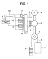
- FIG. 1 shows the construction of an entire brake system of an elevator including the brake control apparatus according to the present invention, and such a situation is similar in respective embodiments to be described later.
- a car 1 of the elevator is hung, together with a counter weight 4, by a main rope 3 wrapped around a sheave 2 of a winch in a well bucket fashion.
- a brake drum 6 adapted to be driven by a hoist motor 5 is generally installed on an axle that couples the hoist motor 5 and the sheave 2 with each other, and a brake shoe 8 is urged into engagement with the brake drum 6 under the action of the resilient force of a spring 7 thereby to provide a braking force due to the friction therebetween.
- electric current is supplied to a brake coil or electromagnet 10 (in the following description, the brake coil will be explained as being the same as the electromagnet) to energize it under the control of a control unit 9, whereby an armature 11 attached to the brake shoe 8 is attracted to the brake coil while overcoming the resilient force of the spring 7.
- a brake contact 12 is turned on by the armature to generate an output 12a, through which it is detected that the attraction of the brake shoe has been completed.
- the brake coil is de-energized similarly by the control unit 9, and at this time, the current supplied to the brake coil is decreased according to a time constant which is decided depending on the resistance and reactance of the coil, so that the attraction of the coil also decreases in accordance with the decreasing brake current.
- the brake coil is separated from the armature 11 and caused to fall or move toward the brake drum under the pull of the spring force.
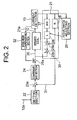
- Fig. 2 is a constructional view that shows the brake control apparatus including the component parts 9, 10 and 13 of Fig. 1 according to the first embodiment of the present invention.
- the inventor focuses attention on the fact that the electromotive force of the brake coil of the electromagnet basically indicates the speed of the armature.
- the electromotive force of this coil is estimated from a current detector signal, based on which the speed of the armature is controlled and adjusted by controlling a voltage command to the brake coil of the electromagnet.
- the current detector 13 detects the electric current that flows through the brake coil (electromagnet).
- An electromotive force estimating section 30 estimates the electromotive force generated by the electromagnet from a coil application voltage command signal 20 to the electromagnet 10 and a current detector signal 21 from the current detector 13.
- a target value setting section (setting section) 22 provides a target value of the electromotive force.
- a difference calculating section 23a calculates a differential (difference) between the target value of the electromotive force and an estimated electromotive force signal.
- a compensating section 24 shapes the gain and phase of an output of the difference calculating section 23a, and outputs it to the electromagnet as the coil application voltage command signal 20.
- a nonlinear compensating section 32 compensates for the electric current flowing through the electromagnet 10.
- an adding section 25a performs the compensation through an adding section 25a in such a manner that an output 21 a of the current detector 13 becomes in a proportional relation to the coil application voltage command signal 20 to the electromagnet.
- An inductance adjusting section 29 adjusts an inductance value 26 of the electromagnet in the electromotive force estimating section 30 in accordance with the current detector signal 21.
- a differentiating section 27 differentiates the current detector signal.
- the brake coil inductance value 26 is actually calculated by a multiplying section by multiplying the differentiation signal of differentiating section by the inductance of the brake coil.
- a brake coil resistance value 28 is actually calculated by the multiplying section by multiplying the current detector signal by the resistance value of the brake coil.
- An adding section 25b adds both of these multiplication signals to each other.
- a difference calculating section 23b subtracts an output of the adding section 25b from the voltage command signal 20 to the brake coil, and outputs it as an estimated electromotive force signal 31.
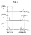
- Fig. 3 is an explanatory view of the operation of the brake control apparatus according to the first embodiment of the present invention.
- (a) in Fig. 3 shows a voltage given to the brake coil
- (b) in Fig. 3 shows the displacement of the armature 11
- (c) in Fig. 3 shows the speed change of the armature 11.
- Fig. 3 when the brake is released, an attraction voltage is applied to the brake coil , so that the electromagnet provided with the brake coil attracts the armature 11 while overcoming the spring 7.
- a hold voltage is applied to the brake coil .
- the hold voltage is set to be a value which is lower than the attraction voltage, and at which the attraction of the electromagnet in its attracting state becomes slightly larger than the spring force. As a result, the heat generation of the brake coil during its attraction can be suppressed.
- the control unit 9 calculates a difference between an output value from a setting section 22 and the estimated electromotive force signal 31 output from the electromotive force estimating section 30 by means of the difference calculating section 23a.
- a differential signal from the difference calculating section, with its amplification factor and phase being controlled by the compensating section 24, is supplied to the brake coil as a control voltage command.
- a compensation voltage is added from the nonlinear compensating section 32 to the adding section 25a so that the electric current flowing through the brake coil 10 becomes in a proportional relation to the voltage command given to the brake coil .
- the compensating section 32 feeds back a voltage which is in proportion to a coil current (current detector signal) of the brake coil detected by the current detector 13.
- the control voltage command is given to the brake coil until a predetermined time point T6 is passed at which the armature 11 ends its falling operation, as shown in (a) of Fig. 3 .
- the amplification factor of the compensating section 24 is set to such a value at which the armature 11 can not be magnetically pulled back to the electromagnet.
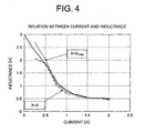
- the electromotive force estimating section 30 estimates the estimated electromotive force signal 31 by using the following expression obtained from the above relational expression: ⁇ L / ⁇ x ⁇ vi ⁇ E - Ri - L di / dt That is, expression (3) above is calculated by the differentiating section 27, the brake coil resistance value 28 and the inductance adjusting section 29.
- the brake coil current i and the inductance L are obtained beforehand, and the relation between the brake coil current i and the inductance L is tabulated.
- the control unit 9 calls or picks up the inductance L from this table based on the output signal of the current detector 13, and changes the inductance L in the electromotive force estimating section 30.
- the brake coil voltage is controlled so as to suppress the falling or moving speed of the brake, so that the falling or moving speed of the brake is slowed down below a prescribed value in comparison with a conventional speed change which is indicated by an alternate long and short dash line in (c) of Fig. 3 .
- the brake operation noise generated upon collision of the brake shoe 8 with the brake drum 6 becomes small.
- an electromotive force estimating section 30 includes a filter section 33b for subjecting a current detector signal to prescribed filtering with a zero point calculated from the inductance and resistance of the electromagnet, a filter section 33a for filtering a voltage command to the electromagnet, and a difference calculating section 23b for calculating a difference between output signals of both of the filter sections. Both of the filter sections have their time constants set to the same value.
- the operation of this embodiment is the same as that of the first embodiment excluding the operation of the electromotive force estimating section 30.
- the electromotive force estimating section 30 performs filtering on the relation of expression (3) above.
- the Laplace transform of an electromotive force signal is represented by Ev(s) and the Laplace transforms of a coil voltage command E and a coil current are further represented by E(s) and i(s), respectively
- the relation of the following expression is obtained by applying, for instance, filtering with a time constant ⁇ to both sides of expression (3) above: 1 / ( ⁇ ⁇ s + 1 ⁇ Ev s ⁇ 1 / ( ⁇ ⁇ s + 1 ⁇ E s - Ls + R / ⁇ ⁇ s + 1 ⁇ i s
- the electromotive force estimating section 30 operates in accordance with expression (4) above, and calculates an estimated electromotive force 31.
- the current detector signal is not subjected to differentiating operation, and hence the brake control apparatus becomes robust with respect to external noise disturbances, so that the brake noise generated upon collision of the brake shoe 8 with the brake drum 6 can be further reduced.
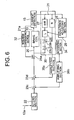
- Fig. 6 is a constructional view that shows a brake control apparatus according to a third embodiment of the present invention.
- the brake control apparatus of Fig. 6 is different from the second embodiment shown in Fig. 2 in the following. That is, the brake control apparatus of this embodiment includes an integrating section 34 for integrating an electromotive force estimated by an electromotive force estimating section 30, an amplifying section 35b for amplifying an output of the integrating section 34, a setting section 22 for providing an integrated value of an electromotive force, i.e., a target value for a position to which the armature is to be displaced, a difference calculating section 23c for calculating a difference between an output signal of the setting section 22 and an output signal from the amplifying section 35b, an amplifying section 35a for amplifying an output signal of the electromotive force estimating section 30, and a difference calculating section 23d for calculating a difference between the output signal of the amplifying section 35a and an output signal of the difference calculating section 23c to output
- an estimated electromotive force is integrated by the integrating section 34, and further amplified by the amplifying section 35b, and a difference between the output of the amplifying section 35b and an output signal of the setting section 22 is calculated by the difference calculating section 23c.
- the difference calculating section 23d calculates a difference between the output signal of the difference calculating section 23c and the estimated electromotive force amplified by the amplifying section 35a, and generates an output signal as a voltage command to the coil.
- the output signal of the difference calculating section 23c becomes a differential signal representative of a difference between an integrated value signal of the electromotive force that increases as the armature begins to move and a fixed value signal of the target value setting section or the setting section 22. Accordingly, the output signal of the difference calculating section 23c decreases gradually in accordance with the movement of the armature.
- the difference calculating section 23d sets, as a new target value, the output signal of the difference calculating section 23c that is decreasing gradually with the movement of the armature, and calculates a difference between this new target value and an estimated electromotive force signal amplified by the amplifying section 35a.
- the electromotive force signal represented by expression (2) is proportional to the product of the armature speed v of and the coil current i.
- the electromotive force signal represented by expression (2) is proportional to the product of the armature speed v of and the coil current i.
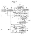
- FIG. 7 is a constructional view that shows a brake control apparatus according to a fourth embodiment of the present invention.
- a compensator adjusting section 36 is further provided.
- this compensator adjusting section 36 includes a latch circuit 37, a comparator 38 and a gain table 39.
- the operation of this embodiment is the same as that of the first embodiment excluding the operation of the compensator adjusting section 36.
- the operation of the compensator adjusting section 36 will be described below.
- the comparator 38 operates to determine the timing at which an electromotive force from the electromotive force estimating section 30 is generated (a reference voltage based on which the presence or absence of the generation of an electromotive force is determined from an estimated electromotive force signal is connected to a lower side terminal of the comparator).
- the latch circuit 37 operates to store an output signal of the current detector 13 at that timing.
- the gain table 39 is a table that serves to associate a current value generated by the electromotive force with an amplification factor in the compensating section 24.
- the compensator adjusting section 36 operates to adjust the amplification factor in the compensating section 24 by means of the gain table 39 in accordance with the coil current value (current detector power output) stored in the latch circuit 37 at each time.
- This has the following advantageous effect. That is, considering the fact that the coil current value, serving to make the armature start to move, is proportional to the urging force of the spring 7, increasing the urging force of the spring increases the amplification factor of the compensating section 24, whereas decreasing the urging force of the spring decreases the amplification factor of the compensating section 24. As a result, the stability in operation of the control system can be improved.
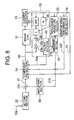
- Fig. 8 is a constructional view that shows a brake control apparatus according to a fifth embodiment of the present invention. Similar to the third embodiment, this fifth embodiment performs control based on an integrated value of an electromotive force, i.e., a variable target value related to the displaced position of the armature.
- the armature operating current detecting section 18 detects a coil current value, at which the armature 11 of the electromagnet 10 starts to operate or move, based on a current detector signal 21.
- the target value setting section 22 provides a target value for an integral signal 310 of an estimated electromotive force signal 31 b amplified by the amplifying section 35.
- the difference calculating section 23c calculates a difference between the target value and the integral signal 310 of the estimated electromotive force signal.
- the compensating section 24 outputs a coil application voltage command signal 20 to the brake coil (electromagnet) based on the output signal of the difference calculating section 23c, the current detector signal 21, the estimated electromotive force signal 31a of the electromotive force estimating section, and an output signal 320 of the armature operating current detecting section 18.
- the inductance adjusting section 29 adjusts an inductance value 26 of the electromagnet in the electromotive force estimating section 30 in accordance with the current detector signal 21.
- a difference calculating section 23b subtracts the output of the adding section 25b from the coil application voltage command signal 20 to the brake coil. Further, an output of the difference calculating section 23b is passed to a filter section 33 which then outputs estimated electromotive force signals 31 a, 31 b.
- Fig. 9 is a constructional view that shows one example of the configuration of the compensating section 24.
- the output signal 31 a of the electromotive force estimating section 30 is input to an electromotive force compensating section 40
- the output signal 320 of the armature operating current detecting section 18 is input to a spring force compensating section 41 and an electromagnetic force compensating section 42.
- the current detector signal 21 is input to the electromagnetic force compensating section 42, a differentiating section 27a and a counterbalance voltage compensating section 47, respectively.
- An output signal of the electromotive force compensating section 40, an output signal of the spring force compensating section 41 and an output signal of the electromagnetic force compensating section 42 are respectively input to a multiplying section 44.
- a difference calculating section 23d calculates a difference between an output signal of the multiplying section 44 and the output signal 17 of the difference calculating section 23c as shown in Fig. 8 , and its output difference is input to a switching section 45.
- An output signal of a zero signal source 48 is also input to the switching section 45.
- An output signal of the differentiating section 27a is input to the switching section 45, too.
- An output signal of the switching section 45 and an output signal of the counterbalance voltage compensating section 47 are added up to each other by an adding section 25c to provide a coil application voltage command signal 20.
- the difference calculating section 23c in the control unit 9 calculates a difference between an output value from the setting section 22 and an estimated electromotive force signal 31 b, which is output from the electromotive force estimating section 30, integrated by the integrating section 34 and amplified by the amplifying section 35.
- the compensating section 24 outputs a coil application voltage command signal 20 to the brake coil (electromagnet) based on the output signal 17 of the difference calculating section 23c, the current detector signal 21, the output signal 31 a of the electromotive force estimating section, and the output signal 320 of the armature operating current detecting section 18.
- the electromotive force compensating section 40 operates to change the gain and phase of the electromotive force estimating signal 31 a by means of a controller having a transfer function represented by the following expression for instance, and generates an output signal which is input to the multiplying section 44.
- C s 250 ⁇ K d ⁇ s + K p / s + 250
- C(s) represents the transfer function between an input signal and an output signal
- s represents a Laplacian operator
- K p represents a constant indicative of a proportional gain
- K d represents a constant indicative of a differential gain.
- expression (6) above is a linear equation in this example, it is needless to say that a multidimensional equation or a nonlinear equation, in which arithmetic expressions are classified and changed according to the magnitude of the signal u, may be used in place of this expression.
- expression (8) above is a linear equation in this example, it is needless to say that a multidimensional equation or a nonlinear equation, in which arithmetic expressions are classified and changed according to the magnitude of the signal i, may be used in place of this expression.
- the multiplying section 44 operates to multiply the output signals of the electromotive force compensating section 40, the spring force compensating section 41 and the electromagnetic force compensating section 42 with one another.
- a difference between the output signal of the multiplying section 44 and the output signal 17 from the difference calculating section 23c is calculated by the difference calculating section 23d, and input therefrom to the switching section 45.
- the switching section 45 operates to switch the output signal of the difference calculating section 23d and the output signal of the zero signal source 48 by the sign of a signal which is obtained by differentiating the coil current detector signal 21 with respect to time by means of the differentiating section 27a.
- q represents a signal which is obtained by differentiating the coil current detector signal 21 with respect to time by means of the differentiating section 27a
- w represents the output signal of the difference calculating section 23d
- z represents the output signal of the switching section 45.
- the adding section 25c adds the output signal of the switching section 45 to an output signal, which is obtained by subjecting the coil current detector signal 21 to the counterbalance voltage compensating section 47, to provide a coil application voltage command signal 20.
- the control operation of the brake control system is as follows.
- the output signal obtained by applying the counterbalance voltage compensating section 47 to the coil current detector signal 21 is constantly output to the coil application voltage command signal.
- the output signal (negative feedback signal) of the difference calculating section 23d is added to the coil application voltage command signal 20.
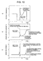
- FIG. 10 shows an example of the operation of the coil application voltage command signal 20 without control (broken line) and under the control of the control apparatus of the present invention (solid line) at the time of brake application;
- (b) in Fig. 10 shows an example of the operation of the armature displacement without control (broken line) and under the control of the control apparatus of the present invention (solid line); and
- (c) in Fig. 10 further shows an example of the operation of the armature speed without control (broken line) and under the control of the control apparatus of the present invention (solid line).
- a maximum value of the speed (solid line) under the control of the present control apparatus at a time point at which the brake shoe is expected to come in contact with the brake drum is smaller than that without control (broken line), so that the falling or actuation speed of the brake is slowed down below a prescribed value in comparison with a conventional speed change which is indicated by the alternate long and short dash line in (c) of Fig. 3 .
- the brake operation noise generated upon collision of the brake shoe 8 with the brake drum 6 becomes small.
- the operation or movement of the armature is started at the instant when the balance of the electromagnetic force and the spring force is changed, and the magnitude of the coil current at this time is substantially proportional to the spring force. Accordingly, there is obtained an advantageous effect that by compensating for the coil application voltage command signal 20 by the output value of the armature operating current detecting section 18, the armature can operate stably even if there is a variation of the spring force.
- the electromagnetic force of the coil is gradually decreasing in accordance with the travel or distance moved of the armature, so the electromagnetic force is not proportional to the voltage applied to the coil. Therefore, it is easier to control the armature speed by gradually increasing the voltage applied to the coil in accordance with the travel or moved distance of the armature.
- the electromagnetic force compensating section 42 generates an output value which is proportional to the difference between the output value of the armature operating current detecting section 18 and the coil current detector signal 21.
- Fig. 11 is a constructional view that shows a compensating section in a brake control apparatus according to a sixth embodiment of the present invention.
- a compensating section 24 is provided with a timer section 43 and a gain changing section 50a.
- the operation of this embodiment is the same as that of the above-mentioned fifth embodiment excluding compensation adjusting operation.
- the timer section 43 counts or measures the time from a time point when the brake is released until brake operation is started.
- Thold the time counted or measured be Thold.
- the gain changing section 50a performs arithmetic calculations as shown by the following.
- the armature is magnetized in accordance with the time during which the brake is being released (i.e., the time during which the armature is attracted to the electromagnet), so it becomes difficult for the armature to separate from the electromagnet even if the coil current gradually decreases upon brake application. Since the gain of the electromotive force compensating section is changed according to the brake release time, the brake operation noise generated upon collision of the brake shoe 8 with the brake drum 6 is reduced without regard to the period of time during which the brake is being released.
- Fig. 12 is a constructional view that shows a brake control apparatus according to a seventh embodiment of the present invention. This embodiment includes a resistance value estimating section 51.
- the operation of this embodiment is the same as that of the fifth embodiment excluding the operation of the resistance value estimating section 51.
- the resistance value estimating section 51 operates to estimate the resistance of the coil from the coil application voltage command signal 20 and the coil current detector signal 21. For example, the resistance is estimated by dividing the result of running average processing of the coil application voltage command signal 20 (an average thereof calculated in a prescribed period) within a certain fixed time during the brake release by the corresponding result of running average processing of the coil current detector signal 21. This estimated resistance value is set as a brake coil resistance value 28 of the electromotive force estimating section 30.
- the electromotive force estimation accuracy of the electromotive force estimating section 30 can be improved, so that the brake operation noise generated upon collision of the brake shoe 8 with the brake drum 6 can be reduced.
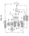
- Fig. 13 is a constructional view that shows the configuration of a compensating section in a brake control apparatus according to an eighth embodiment of the present invention.
- This embodiment includes a second gain changing section 50b in the compensating section 24.
- the operation of this embodiment is the same as that of the above embodiments excluding the operation of the second gain changing section 50b.
- the second gain changing section 50b operates to change the initial gain Kp of the first gain changing section 50a in accordance with the resistance value of the coil (see a broken line arrow in Fig. 12 ) estimated by a resistance value estimating section 51 (for example, the one in Fig. 12 ).
- R* represents the resistance value estimated by the resistance value estimating section 51
- the initial gain Kpini is classified and changed by the magnitude of the estimated resistance value as shown by the following.
- the gain of the electromotive force compensating section 40 can be changed in proportion to an environmental temperature of the brake. As a result, there is obtained an advantageous effect that even if there is a variation in the environmental temperature, stable control can be achieved, so that the brake operation noise generated upon collision of the brake shoe 8 with the brake drum 6 can also be reduced.
- a brake coil voltage is controlled so as to suppress the falling or moving speed of the brake after the brake starts falling or moving, as a result of which the falling or moving speed of the brake is slowed down in comparison with a conventional speed change, thereby reducing the brake operation noise generated upon collision of a brake shoe with a brake drum.
- the falling or moving speed of a brake is slowed down as compared with a conventional speed change, whereby the brake operation noise generated when a brake shoe collides with a brake drum can be reduced.
- an elevator can be used in a place where operation noise thereof gives rise to a problem, thus making it possible to utilize the elevator in much more places.
Claims (11)
- Appareil de commande de frein pour un ascenseur, comprenant:- une section d'estimation de force électromotrice (30) pour estimer une force électromotrice d'un électroaimant (10) à titre de bobine de frein résultant d'une vitesse de déplacement d'une armature (11) attirée vers l'électroaimant (10), laquelle armature (11) entraîne un sabot de frein (8) d'un frein d'ascenseur; et- une section de compensation (24) pour fournir à l'électroaimant (10) un ordre de voltage qui est compensé de façon à accorder la force électromotrice ou une valeur intégrée de la force électromotrice à une valeur cible;dans lequel le voltage fourni à l'électroaimant (10) est commandé de manière à supprimer la vitesse de déplacement de l'armature (11) à un instant (T4) quand l'armature (11) commence à se déplacer en éloignement de sa position de retenue attirée contre l'électroaimant (10).
- Appareil selon la revendication 1,
caractérisé par:- un détecteur de courant (13) pour détecter un courant électrique qui s'écoule à travers l'électroaimant (10) à titre de bobine de frein;- dans lequel la section d'estimation de force électromotrice (30) est adaptée à estimer une force électromotrice générée par l'électroaimant (10) en se basant sur un ordre de voltage à l'électroaimant (10) et sur une sortie du détecteur de courant (13);- une section de fixation de valeur cible (22) pour fournir une valeur cible pour la force électromotrice;- une section de calcul de différence (23a, 23c) pour calculer une différence entre la valeur cible de force électromotrice et la force électromotrice estimée;- dans lequel la section de compensation (24) est adaptée à mettre en forme le gain et la phase d'une sortie de la section de calcul de différence (23a, 23c) pour fournir l'ordre de voltage à l'électroaimant (10);- une section de compensation non linéaire (32) pour effectuer une compensation de manière à faire que la sortie du détecteur de courant (13) et l'ordre de voltage à l'électroaimant (10) présentent une relation proportionnelle l'une avec l'autre; et- une section pour ajuster une valeur d'inductance de l'électroaimant (10) dans la section d'estimation de force électromotrice (30) en accord avec la sortie du détecteur de courant (13). - Appareil selon la revendication 1,
caractérisé par:- un détecteur de courant (13) pour détecter un courant électrique qui s'écoule à travers l'électroaimant (10) à titre de bobine de frein;- dans lequel la section d'estimation de force électromotrice (30) est adaptée à estimer une force électromotrice générée par l'électroaimant (10) en se basant sur un ordre de voltage à l'électroaimant (10) et sur une sortie du détecteur de courant (13);- une section (34) pour intégrer la force électromotrice estimée par la section d'estimation de force électromotrice (30);- une section de fixation de valeur cible (22) pour fournir une valeur cible pour la force électromotrice;- une première section de calcul de différence (23c) pour calculer une différence entre une sortie de la section de fixation de valeur cible (22) et une sortie de la section d'intégration de force électromotrice (34);- une seconde section de calcul de différence (23d) pour calculer une différence entre une sortie de la section d'estimation de force électromotrice (30) et une sortie de la première section de calcul de différence (23c) pour fournir un ordre de voltage à l'électroaimant (10);- une section de compensation non linéaire (32) pour effectuer une compensation de manière à faire que la sortie du détecteur de courant (13) et l'ordre de voltage à l'électroaimant (10) présentent une relation proportionnelle l'une par rapport à l'autre; et- une section pour ajuster une valeur d'inductance de l'électroaimant (10) dans la section d'estimation de force électromotrice (30) en accord avec la sortie du détecteur de courant (13). - Appareil selon la revendication 2,
caractérisé par une section d'ajustement de compensateur (36) pour changer le gain de la section de compensation (24) en accord avec la valeur de sortie du détecteur de courant (13) quand la force électromotrice est générée, en se basant sur la sortie de la section d'estimation de force électromotrice (30) et sur la sortie du détecteur de courant (13). - Appareil selon la revendication 1,
caractérisé par:- un détecteur de courant (13) pour détecter un courant électrique qui s'écoule à travers l'électroaimant (10) à titre de bobine de frein;- dans lequel la section d'estimation de force électromotrice (30) est adaptée à estimer une force électromotrice générée par l'électroaimant (10) en se basant sur un ordre de voltage à l'électroaimant (10) et sur une sortie du détecteur de courant (13);- une section (34) pour intégrer une force électromotrice estimée par la section d'estimation de force électromotrice (30);- une section de fixation de valeur cible (22) pour fournir une valeur cible pour une valeur intégrée de la force électromotrice;- une section de calcul de différence (23c) pour calculer une différence entre une sortie de la section de fixation de valeur cible (22) et une sortie de la section d'intégration de force électromotrice (34);- une section de détection de courant de fonctionnement d'armature (18) pour détecter une valeur du courant de bobine à laquelle l'armature (11) de l'électroaimant (10) commence à fonctionner, en se basant sur la sortie du détecteur de courant (13);- dans lequel la section de compensation (24) est adaptée à fournir un ordre de voltage à l'électroaimant (10) en se basant sur les sorties du détecteur de courant (13), de la section d'estimation de force électromotrice (30), de la section de calcul de différence (23c), et de la section de détection de courant de fonctionnement d'armature (18); et- une section pour ajuster une valeur d'inductance de l'électroaimant (10) dans la section d'estimation de force électromotrice (30) en accord avec la sortie du détecteur de courant (13). - Appareil selon l'une quelconque des revendications 2, 3 et 5, caractérisé ensuite la section d'estimation de force électromotrice (30) comprend:- une section pour différencier la sortie du détecteur de courant (13);- une section pour multiplier le signal différencié par l'inductance de l'électroaimant (10);- une section pour multiplier la sortie du détecteur de courant (13) par une valeur de résistance de l'électroaimant (10);- une section d'addition (25b) dans la section d'estimation pour additionner les deux signaux de multiplication; et- une section de calcul de différence (23b) dans la section d'estimation pour soustraire une sortie de la section d'addition (25b) depuis l'ordre de voltage à l'électroaimant (10).
- Appareil selon l'une quelconque des revendications 2, 3 et 5, caractérisé en ce que la section d'estimation de force électromotrice (30) comprend:- une première section de filtre (33b) pour appliquer à la sortie du détecteur de courant (13) un filtrage prescrit avec un point zéro calculé à partir de l'inductance et de la résistance de l'électroaimant (10);- une seconde section de filtre (33a) pour filtrer l'ordre de voltage à l'électroaimant (10); et- une section de calcul de différence (23b) dans la section d'estimation pour calculer une différence entre les sorties des deux sections de filtre (33a, 33b);- dans lequel les deux sections de filtre (33a, 33b) sont telles que leurs constantes temporelles sont fixées à la même valeur.
- Appareil selon la revendication 5,
caractérisé en ce que la section de compensation (24) comprend:- une section de compensation de force électromotrice (40) pour compenser le gain et la phase de la sortie de la section d'estimation de force électromotrice (30);- une section de compensation de force élastique (41) dont la fonction est de changer sa valeur de sortie en accord avec la sortie de la section de détection de courant de fonctionnement d'armature (18);- une section de compensation de force électromagnétique (42) dont la fonction est de changer sa valeur de sortie pour la baser sur la sortie de la section de détection de courant de fonctionnement d'armature (18) et sur la sortie du détecteur de courant (13);- une section de multiplication (44) dans la section de compensation (24) pour multiplier les sorties de la section de compensation de force électromotrice (40), de la section de compensation de force élastique (41) et de la section de compensation de force électromagnétique (42) les unes avec les autres;- une section de calcul de différence (23d) dans la section de compensation (24) pour calculer une différence entre une sortie de la section de calcul de différence (23c) et une sortie de la section de multiplication (44) dans la section de compensation (24);- une section de différenciation (27a) dans la section de compensation (24) pour différencier la sortie du détecteur de courant (13);- une section de commutation (45) pour commuter entre une sortie de la section de calcul de différence (23d) dans la section de compensation (24) et un signal zéro au moyen d'une sortie de la section de différenciation (27a) dans la section de compensation (24);- une section de compensation de voltage d'équilibrage (47) pour sortir un signal de voltage de manière à équilibrer la force électromagnétique avec une force d'un ressort (7) en accord avec la sortie du détecteur de courant (13); et- une section d'addition (25c) dans la section de compensation (24) pour additionner une sortie de la section de commutation (45) et une sortie de la section de compensation de voltage d'équilibrage (47). - Appareil selon la revendication 8,
caractérisé par:- une section de temporisation (43) pour compter une période temporelle pendant laquelle l'électroaimant (10) attire l'armature (11) pour relâcher ainsi le frein; et- une section (50a) pour changer le gain de la section de compensation de force électromotrice (40) en se basant sur une sortie de la section de temporisation (43). - Appareil selon la revendication 8,
caractérisé par:une section d'estimation de valeur de résistance (51) pour estimer une valeur de résistance de l'électroaimant (10) en se basant sur l'ordre de voltage à l'électroaimant (10) et sur la sortie du détecteur de courant (13) quand l'électroaimant (10) attire l'armature (11), pour relâcher ainsi le frein,la section d'estimation de valeur de résistance (51) ayant pour fonction de changer la valeur de résistance dans la section d'estimation de force électromotrice (30) vers cette valeur estimée. - Appareil selon la revendication 10,
caractérisé par une section (50b) pour changer le gain dans la section de compensation (24) en accord avec une sortie de la section d'estimation de valeur de résistance (51).
Applications Claiming Priority (3)
| Application Number | Priority Date | Filing Date | Title |
|---|---|---|---|
| JP2002283672 | 2002-09-27 | ||
| JP2002283672 | 2002-09-27 | ||
| PCT/JP2003/001385 WO2004028945A1 (fr) | 2002-09-27 | 2003-02-10 | Commande de frein d'ascenseur |
Publications (3)
| Publication Number | Publication Date |
|---|---|
| EP1544148A1 EP1544148A1 (fr) | 2005-06-22 |
| EP1544148A4 EP1544148A4 (fr) | 2008-03-26 |
| EP1544148B1 true EP1544148B1 (fr) | 2012-10-17 |
Family
ID=32040565
Family Applications (1)
| Application Number | Title | Priority Date | Filing Date |
|---|---|---|---|
| EP03703305A Expired - Lifetime EP1544148B1 (fr) | 2002-09-27 | 2003-02-10 | Commande de frein d'ascenseur |
Country Status (5)
| Country | Link |
|---|---|
| EP (1) | EP1544148B1 (fr) |
| JP (1) | JP4102362B2 (fr) |
| KR (1) | KR100572787B1 (fr) |
| CN (1) | CN1325361C (fr) |
| WO (1) | WO2004028945A1 (fr) |
Families Citing this family (19)
| Publication number | Priority date | Publication date | Assignee | Title |
|---|---|---|---|---|
| MY192706A (en) * | 2004-12-17 | 2022-09-02 | Inventio Ag | Lift installation with a braking device, and method for braking and holding a lift installation |
| JP4925105B2 (ja) * | 2005-09-06 | 2012-04-25 | 三菱電機株式会社 | エレベータのブレーキ装置 |
| KR100963357B1 (ko) * | 2005-09-30 | 2010-06-14 | 미쓰비시덴키 가부시키가이샤 | 엘리베이터 장치 |
| KR20100036371A (ko) * | 2006-03-14 | 2010-04-07 | 미쓰비시덴키 가부시키가이샤 | 전자 브레이크 제어 장치 |
| KR200424453Y1 (ko) * | 2006-06-07 | 2006-08-22 | 현대엘리베이터주식회사 | 드럼방식의 직접형 전자 브레이크를 구비한 권양기 |
| JP5073678B2 (ja) * | 2006-12-20 | 2012-11-14 | 三菱電機株式会社 | 電磁ブレーキ制御装置 |
| JP5335903B2 (ja) | 2008-06-17 | 2013-11-06 | オーチス エレベータ カンパニー | 制御回路およびブレーキ制御回路 |
| IT1392823B1 (it) * | 2009-02-04 | 2012-03-23 | Rossi Motoriduttori S P A | Dispositivo di segnalazione di condizione del freno in un freno elettromagnetico particolarmente per motori elettrici |
| JP5474040B2 (ja) * | 2009-02-20 | 2014-04-16 | 三菱電機株式会社 | エレベータのブレーキ装置 |
| WO2011101978A1 (fr) * | 2010-02-19 | 2011-08-25 | 三菱電機株式会社 | Dispositif ascenseur |
| JP5578901B2 (ja) * | 2010-03-19 | 2014-08-27 | 東芝エレベータ株式会社 | エレベータのブレーキ制御装置 |
| JPWO2012140945A1 (ja) * | 2011-04-15 | 2014-07-28 | 三菱電機株式会社 | エレベータ用ブレーキ装置およびエレベータのブレーキ制動方法 |
| US9371873B2 (en) | 2011-06-16 | 2016-06-21 | Otis Elevator Company | Permanent magnet centering system for brake |
| JP5794067B2 (ja) * | 2011-09-16 | 2015-10-14 | 三菱電機株式会社 | エレベータのブレーキ制御装置 |
| US8860352B2 (en) * | 2012-05-10 | 2014-10-14 | Mitsubishi Electric Research Laboratories, Inc. | System and method for controlling actuators |
| FI126171B (fi) | 2014-06-19 | 2016-07-29 | Kone Corp | Järjestelmä, koneistojarru ja menetelmä koneistojarrun ohjaamiseksi |
| DE102018205633A1 (de) * | 2018-04-13 | 2019-10-17 | Thyssenkrupp Ag | Aufzugsanlage |
| WO2021186680A1 (fr) * | 2020-03-19 | 2021-09-23 | 三菱電機株式会社 | Dispositif de commande d'ascenseur |
| CN114988247A (zh) * | 2022-04-27 | 2022-09-02 | 宁波欣达电梯配件厂 | 一种基于电流检测的失电制动控制方法与系统 |
Family Cites Families (9)
| Publication number | Priority date | Publication date | Assignee | Title |
|---|---|---|---|---|
| GB1315589A (en) * | 1970-01-21 | 1973-05-02 | Hitachi Ltd | Control apparatus for an elevator car |
| JPH02110090A (ja) * | 1988-10-18 | 1990-04-23 | Mitsubishi Electric Corp | エレベータ制御装置 |
| JPH0764493B2 (ja) * | 1988-06-27 | 1995-07-12 | 三菱電機株式会社 | エレベータの制御装置 |
| JPH07102949B2 (ja) * | 1989-09-28 | 1995-11-08 | 三菱電機株式会社 | エレベータの制動装置 |
| JPH09267982A (ja) * | 1996-03-29 | 1997-10-14 | Mitsubishi Electric Corp | リニアモータ駆動移動体装置 |
| US5717174A (en) * | 1996-05-08 | 1998-02-10 | Inventio Ag | Elevator brake drop silencing apparatus and method |
| CN1128091C (zh) * | 1999-01-25 | 2003-11-19 | 三菱电机株式会社 | 电梯制动控制装置 |
| JP2001158575A (ja) * | 1999-12-03 | 2001-06-12 | Mitsubishi Electric Corp | エレベータ制御装置 |
| JP4620912B2 (ja) * | 2001-09-11 | 2011-01-26 | 三菱電機株式会社 | 制動システム及びその制御装置 |
-
2003
- 2003-02-10 CN CNB038011212A patent/CN1325361C/zh not_active Expired - Lifetime
- 2003-02-10 EP EP03703305A patent/EP1544148B1/fr not_active Expired - Lifetime
- 2003-02-10 JP JP2004525638A patent/JP4102362B2/ja not_active Expired - Lifetime
- 2003-02-10 KR KR1020047007954A patent/KR100572787B1/ko not_active IP Right Cessation
- 2003-02-10 WO PCT/JP2003/001385 patent/WO2004028945A1/fr active Application Filing
Also Published As
| Publication number | Publication date |
|---|---|
| EP1544148A4 (fr) | 2008-03-26 |
| CN1325361C (zh) | 2007-07-11 |
| JP4102362B2 (ja) | 2008-06-18 |
| JPWO2004028945A1 (ja) | 2006-01-19 |
| KR20040054806A (ko) | 2004-06-25 |
| CN1556770A (zh) | 2004-12-22 |
| WO2004028945A1 (fr) | 2004-04-08 |
| EP1544148A1 (fr) | 2005-06-22 |
| KR100572787B1 (ko) | 2006-04-24 |
Similar Documents
| Publication | Publication Date | Title |
|---|---|---|
| EP1544148B1 (fr) | Commande de frein d'ascenseur | |
| JP4830257B2 (ja) | エレベータのブレーキ制御装置 | |
| US7433170B2 (en) | Apparatus and method of controlling the closing action of a contactor | |
| EP0982643B1 (fr) | Ajustement automatique du gain d'une boucle ouverte de commande de la force d' actuateurs magnétiques pour des suspensions actives d'un ascenceur | |
| US4600865A (en) | Transportation apparatus | |
| US4717865A (en) | Transportation apparatus | |
| JP4275377B2 (ja) | エレベーター用ブレーキ制御装置 | |
| KR100540526B1 (ko) | 차량 개폐체용 제어 장치 | |
| RU2487460C2 (ru) | Способ анализа функционирования электромеханического привода для механизированного управления экраном и привод для его осуществления | |
| WO2006033165A1 (fr) | Detecteur de mouvement d'armature et dispositif d'estimation de position d'armature pour frein d'ascenseur | |
| US20070140669A1 (en) | Method and device for determining the rotary speed of an electrical machine | |
| CN113374791B (zh) | 一种磁悬浮轴承的控制装置、方法和磁悬浮轴承系统 | |
| JP5226203B2 (ja) | 電力変換装置 | |
| FI71537B (fi) | Startregleranordning saerskilt foer hissar | |
| JP5920054B2 (ja) | エレベータ用ブレーキ装置及びエレベータ | |
| JP2008259271A (ja) | サーボ制御装置と定数自動調整方法 | |
| KR900001791B1 (ko) | 제어시스템 | |
| JP2011105484A (ja) | 電磁ブレーキの故障検出装置 | |
| WO2012140945A1 (fr) | Dispositif de frein pour ascenseur et procédé de commande du frein pour un ascenseur | |
| JP4540372B2 (ja) | クラッチパック詰り検出方法、装置、及びクラッチパックの油圧制御装置 | |
| JP6380114B2 (ja) | 車両シート制御装置 | |
| JP2002093619A (ja) | パルス幅変調制御装置 | |
| KR20070024571A (ko) | 엘리베이터 브레이크의 접극자 동작 검출 장치 및 접극자위치 추정 장치 | |
| JP2010000535A (ja) | 板厚制御装置及び板厚制御方法 | |
| JPH08169652A (ja) | リニアモータエレベーターの制御方法 |
Legal Events
| Date | Code | Title | Description |
|---|---|---|---|
| PUAI | Public reference made under article 153(3) epc to a published international application that has entered the european phase |
Free format text: ORIGINAL CODE: 0009012 |
|
| 17P | Request for examination filed |
Effective date: 20040513 |
|
| AK | Designated contracting states |
Kind code of ref document: A1 Designated state(s): AT BE BG CH CY CZ DE DK EE ES FI FR GB GR HU IE IT LI LU MC NL PT SE SI SK TR |
|
| RBV | Designated contracting states (corrected) |
Designated state(s): DE FR |
|
| RAP1 | Party data changed (applicant data changed or rights of an application transferred) |
Owner name: MITSUBISHI DENKI KABUSHIKI KAISHA |
|
| A4 | Supplementary search report drawn up and despatched |
Effective date: 20080227 |
|
| 17Q | First examination report despatched |
Effective date: 20090507 |
|
| GRAP | Despatch of communication of intention to grant a patent |
Free format text: ORIGINAL CODE: EPIDOSNIGR1 |
|
| GRAS | Grant fee paid |
Free format text: ORIGINAL CODE: EPIDOSNIGR3 |
|
| GRAA | (expected) grant |
Free format text: ORIGINAL CODE: 0009210 |
|
| AK | Designated contracting states |
Kind code of ref document: B1 Designated state(s): DE FR |
|
| RIN1 | Information on inventor provided before grant (corrected) |
Inventor name: UEDA, TAKAHARU, C/O MITSUBISHI DENKI K.K. Inventor name: FORRAI, ALEXANDRU,C/O MITSUBISHI DENKI K.K. Inventor name: KARIYA, YOSHITAKA,C/O MITSUBISHI DENKI K.K. |
|
| REG | Reference to a national code |
Ref country code: DE Ref legal event code: R096 Ref document number: 60342352 Country of ref document: DE Effective date: 20121213 |
|
| PLBE | No opposition filed within time limit |
Free format text: ORIGINAL CODE: 0009261 |
|
| STAA | Information on the status of an ep patent application or granted ep patent |
Free format text: STATUS: NO OPPOSITION FILED WITHIN TIME LIMIT |
|
| 26N | No opposition filed |
Effective date: 20130718 |
|
| REG | Reference to a national code |
Ref country code: DE Ref legal event code: R097 Ref document number: 60342352 Country of ref document: DE Effective date: 20130718 |
|
| REG | Reference to a national code |
Ref country code: FR Ref legal event code: ST Effective date: 20131031 |
|
| PG25 | Lapsed in a contracting state [announced via postgrant information from national office to epo] |
Ref country code: FR Free format text: LAPSE BECAUSE OF NON-PAYMENT OF DUE FEES Effective date: 20130228 |
|
| REG | Reference to a national code |
Ref country code: DE Ref legal event code: R084 Ref document number: 60342352 Country of ref document: DE |
|
| REG | Reference to a national code |
Ref country code: DE Ref legal event code: R084 Ref document number: 60342352 Country of ref document: DE Effective date: 20141107 |
|
| PGFP | Annual fee paid to national office [announced via postgrant information from national office to epo] |
Ref country code: DE Payment date: 20211230 Year of fee payment: 20 |
|
| REG | Reference to a national code |
Ref country code: DE Ref legal event code: R071 Ref document number: 60342352 Country of ref document: DE |