EP1544147A2 - Dispositif pneumatique pour le raccordement de fils textiles - Google Patents
Dispositif pneumatique pour le raccordement de fils textiles Download PDFInfo
- Publication number
- EP1544147A2 EP1544147A2 EP04022517A EP04022517A EP1544147A2 EP 1544147 A2 EP1544147 A2 EP 1544147A2 EP 04022517 A EP04022517 A EP 04022517A EP 04022517 A EP04022517 A EP 04022517A EP 1544147 A2 EP1544147 A2 EP 1544147A2
- Authority
- EP
- European Patent Office
- Prior art keywords
- thread
- splicing
- splice
- yarn
- spring wire
- Prior art date
- Legal status (The legal status is an assumption and is not a legal conclusion. Google has not performed a legal analysis and makes no representation as to the accuracy of the status listed.)
- Withdrawn
Links
Images


Classifications
-
- B—PERFORMING OPERATIONS; TRANSPORTING
- B65—CONVEYING; PACKING; STORING; HANDLING THIN OR FILAMENTARY MATERIAL
- B65H—HANDLING THIN OR FILAMENTARY MATERIAL, e.g. SHEETS, WEBS, CABLES
- B65H69/00—Methods of, or devices for, interconnecting successive lengths of material; Knot-tying devices ;Control of the correct working of the interconnecting device
- B65H69/06—Methods of, or devices for, interconnecting successive lengths of material; Knot-tying devices ;Control of the correct working of the interconnecting device by splicing
- B65H69/061—Methods of, or devices for, interconnecting successive lengths of material; Knot-tying devices ;Control of the correct working of the interconnecting device by splicing using pneumatic means
-
- B—PERFORMING OPERATIONS; TRANSPORTING
- B65—CONVEYING; PACKING; STORING; HANDLING THIN OR FILAMENTARY MATERIAL
- B65H—HANDLING THIN OR FILAMENTARY MATERIAL, e.g. SHEETS, WEBS, CABLES
- B65H2701/00—Handled material; Storage means
- B65H2701/30—Handled filamentary material
- B65H2701/31—Textiles threads or artificial strands of filaments
- B65H2701/319—Elastic threads
Definitions
- the invention relates to a yarn splicing apparatus for pneumatic joining of yarns, in particular of Elasthangarnen, according to the preamble of claim 1.
- Yarn splicing devices for the pneumatic joining of yarns have long been known in connection with cross winding machines and are described in detail in numerous patents, for example in DE 40 05 752 A1 or DE 44 20 979 A1.
- two yarn ends which have been formed, for example, by a yarn breakage or by a controlled cleaner cut, can be pneumatically connected so that an almost yarn-like joint is formed. That is, an upper thread that has accumulated on the surface of a cheese is picked up by a suction nozzle and inserted into the splicing channel of the splicing prism of the thread splicer.
- a bobbin thread is picked up by a discharge bobbin positioned in an unwinding position by means of a gripper tube and likewise inserted into the splice channel, where upper and bobbin threads are subsequently pneumatically swirled.
- the two thread ends must first be exactly cut to length and prepared for the splicing process.
- the known thread splicing devices have for this purpose corresponding thread clamping devices, Thread cutting devices and so-called holding and Auflöserschreibchen on.
- the two yarn ends are, while being threaded through the aforementioned handling elements in the splice, respectively also positioned between the holding jaws of a thread clamping device and the cutting tool one of the thread cutting devices, wherein belonging to the respective thread end yarn handling devices respectively on the opposite side of the splice are arranged.
- both upper thread and lower thread are securely fixed in the associated thread clamping devices, the threads are cut to length by the thread cutting devices.
- the cut thread ends are then sucked into the adjacent holding and Auflöserschreibchen and pneumatically prepared there. That is, the thread ends are first largely freed from their Garnwindung, also short fibers are removed.
- the prepared thread ends are pulled by a so-called loop puller into the splice channel of the splicing prism so that they lie parallel to one another approximately at the same height in the splicing channel, but have an opposite orientation.
- An introduced via corresponding inlet holes in the splice air pressure then ensures turbulence of the initially substantially parallel fibers of the two yarn ends, with the result that a nearly yarn-like splice occurs.
- spandex yarns are to be spliced, which generally have a highly elastic core thread surrounded, for example, by cotton fibers. Due to the highly elastic core thread, such spandex yarns tend to pull together strongly after a thread cut, that is, to curl strongly.
- EP 1 118 570 A2 shows and describes a yarn splicing device which, at the level of the holding and dissolving tubes, has additional thread locking means in the form of serrated sheets. These sheets, each fixing one of the thread ends are arranged approximately halfway between the actual thread clamping device and the associated holding and Auflöserschreibchen.
- Thread splicing devices as described in DE 101 24 832 A1
- Thread splicing devices as described in DE 101 24 832 A1
- Thread splicing devices are known in which holding means are arranged in the region of the splice channel, which fix the thread ends during the splicing process.
- the yarn ends are fixed, for example, by two spaced-apart clamps, while the fixation of the yarn ends in the yarn splicing apparatus according to FIG DE 42 26 025 C2 is effected by a centrally arranged, cushion-like, elastic element.
- the compressed air openings, through which the splicing air can be blown into the splice channel, are respectively arranged between the holding means and the splice channel exit in the case of the aforementioned splicing devices.
- double splices are quite durable, they do not represent an almost yarn-like connection and are therefore less suitable for use in the textile industry, in particular for the production of yarns which are to be further processed, for example, into textile fabrics.
- Thread splicing devices for pneumatically connecting To modify yarns so that with such a device also the splicing of problematic yarns, in particular Elasthangarnen, reliably possible.
- Thread splicing apparatus are in the subclaims described.
- the inventive design of a holding means in particular has the advantage that the yarn ends of upper and lower thread are fixed defined immediately after their insertion into the splice through the closing lid member. That is, the thread ends are merely clamped so that they can be pulled into the splice channel after cutting through the thread puller. The thread ends are clamped in the region of the splice channel only on a very small thread section, so that the turbulence of the prepared thread ends is hardly disturbed.
- the thread connections that can be created by the thread splicing device according to the invention are not only sufficiently strong, but also have an almost yarn-like appearance.
- the spring wire is arranged at a distance from the bottom of the splice channel.
- a cross section which is well below the clear cross section of the splice is reliably prevented by such an arrangement that it may cause splice air flow disturbances within the splice through the spring wire which could adversely affect the turbulence of the prepared thread ends.
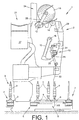
- FIG. 1 shows schematically in side view a textile machine producing cross-wound bobbins, generally designated by the reference numeral 1, in the exemplary embodiment a so-called cross-winding winder.
- Such automatic packages 1 usually have between their (not shown) Endgestellen a variety of similar jobs, in this case winding units 2, on.
- the spin cops 9 produced on a ring spinning machine are rewound to large-volume cheeses 15 on these winding stations 2.
- these cheeses 15 by means of an automatically operating (not shown) service unit, preferably a cheese changer, handed over to a machine-length cheese package transport means 21 and transported to a machine end side Spulenverladestation or the like.
- Such spoolers 1 also have a Logistics facility in the form of a coil and Sleeve transport system 3 on. In this coil and Sleeve transport system 3 run, on transport plates 8, the Spinnkopse 9 or empty tubes to.
- Such a cross-winding machine has 1 usually via a (not shown) Central control unit via a machine bus with both the separate workstation computers 29 of the individual Spooling 2 as well as with a control device of the Service units is connected.
- the delivered spinning cops 9 are rewound in the Abspul einen AS, each located in the region of the transverse transport sections 6 at the winding units 2, to large-volume cheeses 15.
- the individual winding units have for this purpose, as also known and therefore only hinted at various facilities that ensure proper operation of these jobs.
- These devices are for example a suction nozzle 12, a gripper tube 25 and a thread connecting device 10.
- the suction nozzle 12 and the gripper tube 25 are each connected via suction air connections to a machine-length suction channel 37.
- the suction nozzle 12 is pivotally mounted about an axis of rotation 16 and the gripper tube 25 about a rotational axis 26 limited.
- Thread tensioner a Thread cleaner, a waxing device, a thread cutting device, a yarn tension force sensor and a bobbin thread sensor.
- the thread connecting device is designed as a pneumatic yarn splicing device 10 and arranged slightly set back with respect to the regular yarn path.
- an upper thread clamping and cutting device 11 and a lower thread clamping and cutting device 17 are arranged.
- the winding of the cheeses 15 takes place on a winding device 24.
- a winding device 24 have inter alia a coil frame 28 which is movably mounted about a pivot axis 13 and has means for rotatably supporting a cheese package.
- a coil frame 28 which is movably mounted about a pivot axis 13 and has means for rotatably supporting a cheese package.
- cross-wound bobbin 15 lies with its surface on a Nuttrommel 14 and is driven by this frictional engagement.
- FIG. 2 shows a top view of the thread splicing device 10 according to the invention. As can be seen, above and below the yarn splicing apparatus 10 thread clamping and cutting devices 11 and 17 are arranged. In addition, in Fig.2, the gripper tube 25 for handling the lower thread 32 and the suction nozzle 12 for handling the upper thread 31 are shown.
- the thread splicing device 10 consists essentially of an air distribution block 33, in the so-called Auflöserschreibchen 34 are inserted, a splicing prism 19 with a pneumatically acted splice 20 and a limited in a pivot axis 30 rotatably mounted Cover element 23.
- the splicing prism 19 In the installed state of the splicing prism 19 are in the Splice channel 20 opening injection openings 22 with a Pneumatic bore in the air distribution block 33 in conjunction, the via an appropriate line, in which, for example, a Solenoid valve is switched on, to a Compressed air source connected.
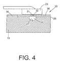
- a groove 35 is inserted, in which a spring wire 36 is mounted limitedly movable.
- the spring wire 36 which is fixed, for example, in a nip 38, is orthogonal to the splice 20 so arranged that a positioned on the spring wire 36 thread end (31, 32) is clamped when closing the lid member 23 between the spring wire 36 and cover member 23.
- the lid member 23 is um a pivot axis 30 limited rotatably mounted and can over a (shown schematically) pivot drive 47 defined be controlled.
- the spring wire 36 merely intersects the splice channel 20 in its upper region. That is, the splicing air supplied via the injection openings 22 can, as usual, spread over the entire length of the splice channel 20, while swirling the thread ends of the upper thread 31 and lower thread 32 into a splicing that is almost identical to the yarn.
- the thread splicing device In the case of reciprocating machines, a distinction is essentially made between two types of winding interruptions.
- the first type for example, includes the emptying of the spinning cop 9 or a thread break below the thread tensioner, makes a so-called bobbin change circuit necessary, that is, the spinning cop located in the winding position 9 or a corresponding empty tube must be replaced with a new spinning cop.
- a new bobbin thread 32 is ready, which can be inserted through the gripper tube 25 in the splice 20 of the pneumatic thread splicer 10.
- the lower thread 32 is held in the thread tensioner, as a thread cleaner has triggered the thread clamping function of the thread tensioner due to the absence of a dynamic thread signal.
- the lower thread 32 held in the thread tensioner is picked up by the gripper tube 25, which initially pivots into the area of the thread tensioner for this purpose and there sucks the lower thread 32, which is released by the thread tensioner.
- the gripper tube 25 pivots into its upper working position indicated in FIG.
- the lower thread 32 is inserted via the thread insertion slot 18 into the splicing channel 20 of the splicing head 19 and into the clamping element 17 'of the lower and the cutting element 11 "of the upper thread cutting and clamping device 17 or 11. That is, the lower thread 32 is inserted
- the upper thread 31 accumulated on the cross-wound bobbin 15 is picked up by the suction nozzle 12 and also inserted into the splicing channel 20 of the yarn splicing device 10.
- the suction nozzle 12 threads the upper thread 31 over the latter Fadeneinlegeschlitz 18 in the splice 20 of the splice head 19 and in the Clamping element 11 'of the upper and the cutting element 17 "of the lower thread clamping and cutting device 11 or 17.
- the splice channel 20 is closed. That is, the lid member 23 is transferred by means of the pivot drive 47 in the splicing position.
- the drawn over the spring wire 36 thread ends of upper thread 32 and lower thread 31 are thereby defined defined by the lid member 23.
Landscapes
- Spinning Or Twisting Of Yarns (AREA)
Applications Claiming Priority (2)
| Application Number | Priority Date | Filing Date | Title |
|---|---|---|---|
| DE10359570 | 2003-12-18 | ||
| DE2003159570 DE10359570A1 (de) | 2003-12-18 | 2003-12-18 | Fadenspleißvorrichtung zum pneumatischen Verbinden von Garnen |
Publications (2)
| Publication Number | Publication Date |
|---|---|
| EP1544147A2 true EP1544147A2 (fr) | 2005-06-22 |
| EP1544147A3 EP1544147A3 (fr) | 2005-12-07 |
Family
ID=34485469
Family Applications (1)
| Application Number | Title | Priority Date | Filing Date |
|---|---|---|---|
| EP04022517A Withdrawn EP1544147A3 (fr) | 2003-12-18 | 2004-09-22 | Dispositif pneumatique pour le raccordement de fils textiles |
Country Status (3)
| Country | Link |
|---|---|
| EP (1) | EP1544147A3 (fr) |
| CN (1) | CN1629375A (fr) |
| DE (1) | DE10359570A1 (fr) |
Cited By (4)
| Publication number | Priority date | Publication date | Assignee | Title |
|---|---|---|---|---|
| EP1671910A3 (fr) * | 2004-12-16 | 2006-08-09 | Murata Kikai Kabushiki Kaisha | Dispositif d'épissure de fils |
| CN110577114A (zh) * | 2019-10-10 | 2019-12-17 | 上海枭腾纺织科技有限公司 | 全自动智能打结器 |
| EP3686142A1 (fr) * | 2019-01-24 | 2020-07-29 | Murata Machinery, Ltd. | Dispositif d'assemblage de fil et dispositif de bobinage de fil |
| EP3736236A1 (fr) * | 2019-05-08 | 2020-11-11 | Heberlein AG | Tête d'épissure pour un dispositif d'épissure, dispositif d'épissure doté d'au moins une tête d'épissure, procédé d'épissure de fils au moyen d'une tête d'épissure, produit de programme informatique |
Families Citing this family (13)
| Publication number | Priority date | Publication date | Assignee | Title |
|---|---|---|---|---|
| CN101397701B (zh) * | 2008-04-07 | 2011-07-13 | 上海凯利纺织五金有限公司 | 可装卸的气路集成块及其自动空捻器 |
| DE102011101629A1 (de) | 2011-05-14 | 2012-11-15 | Oerlikon Textile Gmbh & Co. Kg | Fadenspleißvorrichtung für eine Arbeitsstelle einer Kreuzspulen herstellenden Textilmaschine |
| DE102014018626A1 (de) * | 2014-12-13 | 2016-06-16 | Saurer Germany Gmbh & Co. Kg | Axial geteilte Spleißkanaleinheit mit zwei radial versetzten Kammern und scharfen Stoßkanten zwischen den Kammern, Spleißer mit einer solchen Spleißkanaleinheit und Textilmaschine mit einem solchen Spleißer |
| DE102015014384A1 (de) | 2015-11-09 | 2017-05-11 | Saurer Germany Gmbh & Co. Kg | Fadenleitblechelement für eine Fadenspleissvorrichtung einer Arbeitsstelle einer Spulmaschine, Fadenspleissvorrichtung und Verfahren zum Betreiben der Arbeitsstelle |
| DE102016002695A1 (de) * | 2016-03-08 | 2017-09-14 | Saurer Germany Gmbh & Co. Kg | Fadenspleißvorrichtung für eine Arbeitsstelle einer Kreuzspulen herstellenden Textilmaschine |
| DE102016121093A1 (de) * | 2016-11-04 | 2018-05-09 | Saurer Germany Gmbh & Co. Kg | Fadenspleißvorrichtung |
| DE102016123451A1 (de) * | 2016-12-05 | 2018-06-07 | Saurer Germany Gmbh & Co. Kg | Fadenspleißvorrichtung |
| DE102017114707A1 (de) * | 2017-06-30 | 2019-01-03 | Saurer Spinning Solutions Gmbh & Co. Kg | Fadenspleißvorrichtung zum pneumatischen Verbinden von Fadenenden |
| DE102017129582A1 (de) * | 2017-12-12 | 2019-06-13 | Saurer Spinning Solutions Gmbh & Co. Kg | Fadenspleißvorrichtung für eine Textilmaschine |
| DE102018006472A1 (de) * | 2018-08-16 | 2020-02-20 | Saurer Spinning Solutions Gmbh & Co. Kg | Spleißvorrichtung |
| CN110077909A (zh) * | 2019-05-11 | 2019-08-02 | 海盐新创制衣有限公司 | 络筒纱线无线头接线装置 |
| CN112125064A (zh) * | 2020-09-28 | 2020-12-25 | 安徽日发纺织机械有限公司 | 一种气动捻接装置及其捻接方法 |
| CN118753925A (zh) * | 2024-07-22 | 2024-10-11 | 杭州和兴碳纤维科技有限公司 | 一种碳纤维在线接丝枪及其使用方法 |
Family Cites Families (8)
| Publication number | Priority date | Publication date | Assignee | Title |
|---|---|---|---|---|
| BE625194A (fr) * | 1961-11-23 | |||
| JPS55106968A (en) * | 1979-02-09 | 1980-08-16 | Murata Mach Ltd | Pneumatic type thread connector |
| JPH0645428B2 (ja) * | 1989-02-15 | 1994-06-15 | 村田機械株式会社 | スプライサの点検方法 |
| DE4005752C2 (de) * | 1990-02-23 | 1998-10-08 | Schlafhorst & Co W | Verfahren und Vorrichtung zum Vorbereiten zu spleißender Fadenenden |
| IT1239341B (it) * | 1990-02-26 | 1993-10-20 | Mesdan Spa | Dispositivo per la giunzione di fili e filati tessili mediante aria compressa |
| DE4226025C2 (de) * | 1991-09-19 | 1996-10-24 | Akzo Nobel Nv | Vorrichtung zum Spleißen von Multifilamentgarnen |
| DE4420979B4 (de) * | 1994-06-16 | 2005-09-01 | Saurer Gmbh & Co. Kg | Fadenendevorbereitungseinrichtung für Kreuzspulen herstellende Textilmaschinen |
| DE10124832A1 (de) * | 2001-05-22 | 2002-11-28 | Schlafhorst & Co W | Fadenspleissvorrichtung |
-
2003
- 2003-12-18 DE DE2003159570 patent/DE10359570A1/de not_active Withdrawn
-
2004
- 2004-09-22 EP EP04022517A patent/EP1544147A3/fr not_active Withdrawn
- 2004-12-17 CN CN 200410102001 patent/CN1629375A/zh active Pending
Cited By (7)
| Publication number | Priority date | Publication date | Assignee | Title |
|---|---|---|---|---|
| EP1671910A3 (fr) * | 2004-12-16 | 2006-08-09 | Murata Kikai Kabushiki Kaisha | Dispositif d'épissure de fils |
| EP3686142A1 (fr) * | 2019-01-24 | 2020-07-29 | Murata Machinery, Ltd. | Dispositif d'assemblage de fil et dispositif de bobinage de fil |
| EP3736236A1 (fr) * | 2019-05-08 | 2020-11-11 | Heberlein AG | Tête d'épissure pour un dispositif d'épissure, dispositif d'épissure doté d'au moins une tête d'épissure, procédé d'épissure de fils au moyen d'une tête d'épissure, produit de programme informatique |
| WO2020224874A1 (fr) * | 2019-05-08 | 2020-11-12 | Heberlein Ag | Tête d'épissurage destinée à un appareil d'épissurage, dispositif d'épissurage comprenant au moins une tête d'épissurage, procédé d'épissurage d'un fil à une tête d'épissurage, produit programme informatique |
| US11912528B2 (en) | 2019-05-08 | 2024-02-27 | Heberlein Technology Ag | Splice head for a splicer, splice device having at least one splice head, method for splicing yarn using a splice head, computer program product |
| CN110577114A (zh) * | 2019-10-10 | 2019-12-17 | 上海枭腾纺织科技有限公司 | 全自动智能打结器 |
| CN110577114B (zh) * | 2019-10-10 | 2024-03-15 | 上海枭腾纺织科技有限公司 | 全自动智能打结器 |
Also Published As
| Publication number | Publication date |
|---|---|
| CN1629375A (zh) | 2005-06-22 |
| DE10359570A1 (de) | 2005-07-28 |
| EP1544147A3 (fr) | 2005-12-07 |
Similar Documents
| Publication | Publication Date | Title |
|---|---|---|
| EP1331192B1 (fr) | Dispositif pour raccorder pneumatiquement les extrémités de fils | |
| DE102011101629A1 (de) | Fadenspleißvorrichtung für eine Arbeitsstelle einer Kreuzspulen herstellenden Textilmaschine | |
| DE10124832A1 (de) | Fadenspleissvorrichtung | |
| DE102016002695A1 (de) | Fadenspleißvorrichtung für eine Arbeitsstelle einer Kreuzspulen herstellenden Textilmaschine | |
| DE10359570A1 (de) | Fadenspleißvorrichtung zum pneumatischen Verbinden von Garnen | |
| DE102012005861A1 (de) | Fadenspleißvorrichtung für eine Kreuzspulen herstellende Textilmaschine | |
| DE102017114707A1 (de) | Fadenspleißvorrichtung zum pneumatischen Verbinden von Fadenenden | |
| DE102016119542A1 (de) | Fadenspleißvorrichtung für eine Arbeitsstelle einer Kreuzspulen herstellenden Textilmaschine | |
| DE4420979A1 (de) | Fadenendevorbereitungseinrichtung für Kreuzspulen herstellende Textilmaschinen | |
| DE102018101925A1 (de) | Spleißprisma für eine Spleißvorrichtung | |
| EP1380529B1 (fr) | Dispositif d'épissure de fils | |
| DE102011111033A1 (de) | Fadenspleißvorrichtung für eine Kreuzspulen herstellende Textilmaschine | |
| EP2066577A1 (fr) | Buse aspirante pour un poste de travail d'une machine textile fabriquant des bobines croisées | |
| DE102015016664A1 (de) | Fadenspleißvorrichtung | |
| DE102018120457A1 (de) | Fadenspleißvorrichtung für eine Arbeitsstelle einer Kreuzspulen herstellenden Textilmaschine | |
| EP1076028A2 (fr) | Dispositif de rattachement du fil pour une machine textile fabriquant des bobines à spires croisées | |
| EP1971545B1 (fr) | Dispositif d'epissage de fils pour machine textile qui forme des bobines croisees | |
| DE102017102432A1 (de) | Spleißprisma für eine Fadenspleißvorrichtung einer Arbeitsstelle einer Kreuzspulen herstellenden Textilmaschine und Einsatzteil für das Spleißprisma | |
| EP1151951A2 (fr) | Procédé de fonctionnement d'une machine textile pour la fabrication de bobines à spires croisées | |
| DE102018108151A1 (de) | Fadenspleißvorrichtung für eine Arbeitsstelle einer Kreuzspulen herstellenden Textilmaschine | |
| DE10007950A1 (de) | Vorrichtung zur Inbetriebnahme einer Arbeitsstelle einer Kreuzspulen herstellenden Textilmaschine | |
| DE102010035067A1 (de) | Verfahren zum Betreiben einer Arbeitsstelle eines Kreuzspulautomaten sowie Fadenspleißvorrichtung zur Durchführung des Verfahrens | |
| DE102020132458A1 (de) | Fadenspleißvorrichtung für eine Arbeitsstelle einer Kreuzspulen herstellenden Textilmaschine | |
| EP1828040B1 (fr) | Poste de travail de bobineuse | |
| DE102017129580A1 (de) | Rotationsspleißer für eine Arbeitsstelle auf einer Kreuzspulen herstellenden Textilmaschine |
Legal Events
| Date | Code | Title | Description |
|---|---|---|---|
| PUAI | Public reference made under article 153(3) epc to a published international application that has entered the european phase |
Free format text: ORIGINAL CODE: 0009012 |
|
| AK | Designated contracting states |
Kind code of ref document: A2 Designated state(s): AT BE BG CH CY CZ DE DK EE ES FI FR GB GR HU IE IT LI LU MC NL PL PT RO SE SI SK TR |
|
| AX | Request for extension of the european patent |
Extension state: AL HR LT LV MK |
|
| PUAL | Search report despatched |
Free format text: ORIGINAL CODE: 0009013 |
|
| AK | Designated contracting states |
Kind code of ref document: A3 Designated state(s): AT BE BG CH CY CZ DE DK EE ES FI FR GB GR HU IE IT LI LU MC NL PL PT RO SE SI SK TR |
|
| AX | Request for extension of the european patent |
Extension state: AL HR LT LV MK |
|
| 17P | Request for examination filed |
Effective date: 20060607 |
|
| GRAP | Despatch of communication of intention to grant a patent |
Free format text: ORIGINAL CODE: EPIDOSNIGR1 |
|
| AKX | Designation fees paid |
Designated state(s): DE IT TR |
|
| STAA | Information on the status of an ep patent application or granted ep patent |
Free format text: STATUS: THE APPLICATION IS DEEMED TO BE WITHDRAWN |
|
| 18D | Application deemed to be withdrawn |
Effective date: 20061228 |