EP1544147A2 - Apparatus for splicing yarns pneumatically - Google Patents
Apparatus for splicing yarns pneumatically Download PDFInfo
- Publication number
- EP1544147A2 EP1544147A2 EP04022517A EP04022517A EP1544147A2 EP 1544147 A2 EP1544147 A2 EP 1544147A2 EP 04022517 A EP04022517 A EP 04022517A EP 04022517 A EP04022517 A EP 04022517A EP 1544147 A2 EP1544147 A2 EP 1544147A2
- Authority
- EP
- European Patent Office
- Prior art keywords
- thread
- splicing
- splice
- yarn
- spring wire
- Prior art date
- Legal status (The legal status is an assumption and is not a legal conclusion. Google has not performed a legal analysis and makes no representation as to the accuracy of the status listed.)
- Withdrawn
Links
Images


Classifications
-
- B—PERFORMING OPERATIONS; TRANSPORTING
- B65—CONVEYING; PACKING; STORING; HANDLING THIN OR FILAMENTARY MATERIAL
- B65H—HANDLING THIN OR FILAMENTARY MATERIAL, e.g. SHEETS, WEBS, CABLES
- B65H69/00—Methods of, or devices for, interconnecting successive lengths of material; Knot-tying devices ;Control of the correct working of the interconnecting device
- B65H69/06—Methods of, or devices for, interconnecting successive lengths of material; Knot-tying devices ;Control of the correct working of the interconnecting device by splicing
- B65H69/061—Methods of, or devices for, interconnecting successive lengths of material; Knot-tying devices ;Control of the correct working of the interconnecting device by splicing using pneumatic means
-
- B—PERFORMING OPERATIONS; TRANSPORTING
- B65—CONVEYING; PACKING; STORING; HANDLING THIN OR FILAMENTARY MATERIAL
- B65H—HANDLING THIN OR FILAMENTARY MATERIAL, e.g. SHEETS, WEBS, CABLES
- B65H2701/00—Handled material; Storage means
- B65H2701/30—Handled filamentary material
- B65H2701/31—Textiles threads or artificial strands of filaments
- B65H2701/319—Elastic threads
Definitions
- the invention relates to a yarn splicing apparatus for pneumatic joining of yarns, in particular of Elasthangarnen, according to the preamble of claim 1.
- Yarn splicing devices for the pneumatic joining of yarns have long been known in connection with cross winding machines and are described in detail in numerous patents, for example in DE 40 05 752 A1 or DE 44 20 979 A1.
- two yarn ends which have been formed, for example, by a yarn breakage or by a controlled cleaner cut, can be pneumatically connected so that an almost yarn-like joint is formed. That is, an upper thread that has accumulated on the surface of a cheese is picked up by a suction nozzle and inserted into the splicing channel of the splicing prism of the thread splicer.
- a bobbin thread is picked up by a discharge bobbin positioned in an unwinding position by means of a gripper tube and likewise inserted into the splice channel, where upper and bobbin threads are subsequently pneumatically swirled.
- the two thread ends must first be exactly cut to length and prepared for the splicing process.
- the known thread splicing devices have for this purpose corresponding thread clamping devices, Thread cutting devices and so-called holding and Auflöserschreibchen on.
- the two yarn ends are, while being threaded through the aforementioned handling elements in the splice, respectively also positioned between the holding jaws of a thread clamping device and the cutting tool one of the thread cutting devices, wherein belonging to the respective thread end yarn handling devices respectively on the opposite side of the splice are arranged.
- both upper thread and lower thread are securely fixed in the associated thread clamping devices, the threads are cut to length by the thread cutting devices.
- the cut thread ends are then sucked into the adjacent holding and Auflöserschreibchen and pneumatically prepared there. That is, the thread ends are first largely freed from their Garnwindung, also short fibers are removed.
- the prepared thread ends are pulled by a so-called loop puller into the splice channel of the splicing prism so that they lie parallel to one another approximately at the same height in the splicing channel, but have an opposite orientation.
- An introduced via corresponding inlet holes in the splice air pressure then ensures turbulence of the initially substantially parallel fibers of the two yarn ends, with the result that a nearly yarn-like splice occurs.
- spandex yarns are to be spliced, which generally have a highly elastic core thread surrounded, for example, by cotton fibers. Due to the highly elastic core thread, such spandex yarns tend to pull together strongly after a thread cut, that is, to curl strongly.
- EP 1 118 570 A2 shows and describes a yarn splicing device which, at the level of the holding and dissolving tubes, has additional thread locking means in the form of serrated sheets. These sheets, each fixing one of the thread ends are arranged approximately halfway between the actual thread clamping device and the associated holding and Auflöserschreibchen.
- Thread splicing devices as described in DE 101 24 832 A1
- Thread splicing devices as described in DE 101 24 832 A1
- Thread splicing devices are known in which holding means are arranged in the region of the splice channel, which fix the thread ends during the splicing process.
- the yarn ends are fixed, for example, by two spaced-apart clamps, while the fixation of the yarn ends in the yarn splicing apparatus according to FIG DE 42 26 025 C2 is effected by a centrally arranged, cushion-like, elastic element.
- the compressed air openings, through which the splicing air can be blown into the splice channel, are respectively arranged between the holding means and the splice channel exit in the case of the aforementioned splicing devices.
- double splices are quite durable, they do not represent an almost yarn-like connection and are therefore less suitable for use in the textile industry, in particular for the production of yarns which are to be further processed, for example, into textile fabrics.
- Thread splicing devices for pneumatically connecting To modify yarns so that with such a device also the splicing of problematic yarns, in particular Elasthangarnen, reliably possible.
- Thread splicing apparatus are in the subclaims described.
- the inventive design of a holding means in particular has the advantage that the yarn ends of upper and lower thread are fixed defined immediately after their insertion into the splice through the closing lid member. That is, the thread ends are merely clamped so that they can be pulled into the splice channel after cutting through the thread puller. The thread ends are clamped in the region of the splice channel only on a very small thread section, so that the turbulence of the prepared thread ends is hardly disturbed.
- the thread connections that can be created by the thread splicing device according to the invention are not only sufficiently strong, but also have an almost yarn-like appearance.
- the spring wire is arranged at a distance from the bottom of the splice channel.
- a cross section which is well below the clear cross section of the splice is reliably prevented by such an arrangement that it may cause splice air flow disturbances within the splice through the spring wire which could adversely affect the turbulence of the prepared thread ends.
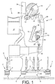
- FIG. 1 shows schematically in side view a textile machine producing cross-wound bobbins, generally designated by the reference numeral 1, in the exemplary embodiment a so-called cross-winding winder.
- Such automatic packages 1 usually have between their (not shown) Endgestellen a variety of similar jobs, in this case winding units 2, on.
- the spin cops 9 produced on a ring spinning machine are rewound to large-volume cheeses 15 on these winding stations 2.
- these cheeses 15 by means of an automatically operating (not shown) service unit, preferably a cheese changer, handed over to a machine-length cheese package transport means 21 and transported to a machine end side Spulenverladestation or the like.
- Such spoolers 1 also have a Logistics facility in the form of a coil and Sleeve transport system 3 on. In this coil and Sleeve transport system 3 run, on transport plates 8, the Spinnkopse 9 or empty tubes to.
- Such a cross-winding machine has 1 usually via a (not shown) Central control unit via a machine bus with both the separate workstation computers 29 of the individual Spooling 2 as well as with a control device of the Service units is connected.
- the delivered spinning cops 9 are rewound in the Abspul einen AS, each located in the region of the transverse transport sections 6 at the winding units 2, to large-volume cheeses 15.
- the individual winding units have for this purpose, as also known and therefore only hinted at various facilities that ensure proper operation of these jobs.
- These devices are for example a suction nozzle 12, a gripper tube 25 and a thread connecting device 10.
- the suction nozzle 12 and the gripper tube 25 are each connected via suction air connections to a machine-length suction channel 37.
- the suction nozzle 12 is pivotally mounted about an axis of rotation 16 and the gripper tube 25 about a rotational axis 26 limited.
- Thread tensioner a Thread cleaner, a waxing device, a thread cutting device, a yarn tension force sensor and a bobbin thread sensor.
- the thread connecting device is designed as a pneumatic yarn splicing device 10 and arranged slightly set back with respect to the regular yarn path.
- an upper thread clamping and cutting device 11 and a lower thread clamping and cutting device 17 are arranged.
- the winding of the cheeses 15 takes place on a winding device 24.
- a winding device 24 have inter alia a coil frame 28 which is movably mounted about a pivot axis 13 and has means for rotatably supporting a cheese package.
- a coil frame 28 which is movably mounted about a pivot axis 13 and has means for rotatably supporting a cheese package.
- cross-wound bobbin 15 lies with its surface on a Nuttrommel 14 and is driven by this frictional engagement.
- FIG. 2 shows a top view of the thread splicing device 10 according to the invention. As can be seen, above and below the yarn splicing apparatus 10 thread clamping and cutting devices 11 and 17 are arranged. In addition, in Fig.2, the gripper tube 25 for handling the lower thread 32 and the suction nozzle 12 for handling the upper thread 31 are shown.
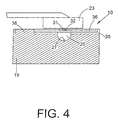
- the thread splicing device 10 consists essentially of an air distribution block 33, in the so-called Auflöserschreibchen 34 are inserted, a splicing prism 19 with a pneumatically acted splice 20 and a limited in a pivot axis 30 rotatably mounted Cover element 23.
- the splicing prism 19 In the installed state of the splicing prism 19 are in the Splice channel 20 opening injection openings 22 with a Pneumatic bore in the air distribution block 33 in conjunction, the via an appropriate line, in which, for example, a Solenoid valve is switched on, to a Compressed air source connected.
- a groove 35 is inserted, in which a spring wire 36 is mounted limitedly movable.
- the spring wire 36 which is fixed, for example, in a nip 38, is orthogonal to the splice 20 so arranged that a positioned on the spring wire 36 thread end (31, 32) is clamped when closing the lid member 23 between the spring wire 36 and cover member 23.
- the lid member 23 is um a pivot axis 30 limited rotatably mounted and can over a (shown schematically) pivot drive 47 defined be controlled.
- the spring wire 36 merely intersects the splice channel 20 in its upper region. That is, the splicing air supplied via the injection openings 22 can, as usual, spread over the entire length of the splice channel 20, while swirling the thread ends of the upper thread 31 and lower thread 32 into a splicing that is almost identical to the yarn.
- the thread splicing device In the case of reciprocating machines, a distinction is essentially made between two types of winding interruptions.
- the first type for example, includes the emptying of the spinning cop 9 or a thread break below the thread tensioner, makes a so-called bobbin change circuit necessary, that is, the spinning cop located in the winding position 9 or a corresponding empty tube must be replaced with a new spinning cop.
- a new bobbin thread 32 is ready, which can be inserted through the gripper tube 25 in the splice 20 of the pneumatic thread splicer 10.
- the lower thread 32 is held in the thread tensioner, as a thread cleaner has triggered the thread clamping function of the thread tensioner due to the absence of a dynamic thread signal.
- the lower thread 32 held in the thread tensioner is picked up by the gripper tube 25, which initially pivots into the area of the thread tensioner for this purpose and there sucks the lower thread 32, which is released by the thread tensioner.
- the gripper tube 25 pivots into its upper working position indicated in FIG.
- the lower thread 32 is inserted via the thread insertion slot 18 into the splicing channel 20 of the splicing head 19 and into the clamping element 17 'of the lower and the cutting element 11 "of the upper thread cutting and clamping device 17 or 11. That is, the lower thread 32 is inserted
- the upper thread 31 accumulated on the cross-wound bobbin 15 is picked up by the suction nozzle 12 and also inserted into the splicing channel 20 of the yarn splicing device 10.
- the suction nozzle 12 threads the upper thread 31 over the latter Fadeneinlegeschlitz 18 in the splice 20 of the splice head 19 and in the Clamping element 11 'of the upper and the cutting element 17 "of the lower thread clamping and cutting device 11 or 17.
- the splice channel 20 is closed. That is, the lid member 23 is transferred by means of the pivot drive 47 in the splicing position.
- the drawn over the spring wire 36 thread ends of upper thread 32 and lower thread 31 are thereby defined defined by the lid member 23.
Landscapes
- Spinning Or Twisting Of Yarns (AREA)
Abstract
Description
Die Erfindung betrifft eine Fadenspleißvorrichtung zum
pneumatischen Verbinden von Garnen, insbesondere von
Elasthangarnen, gemäß dem Oberbegriff des Anspruches 1.The invention relates to a yarn splicing apparatus for
pneumatic joining of yarns, in particular of
Elasthangarnen, according to the preamble of
Fadenspleißvorrichtungen zum pneumatischen Verbinden von
Garnen sind im Zusammenhang mit Kreuzspulmaschinen seit langem
bekannt und in zahlreichen Patentschriften, zum Beispiel in
der DE 40 05 752 A1 oder der DE 44 20 979 A1, ausführlich
beschrieben.
Mit diesen bekannten Fadenspleißvorrichtungen können zwei
Fadenenden, die beispielsweise durch einen Fadenbruch oder
durch einen kontrollierten Reinigerschnitt entstanden sind,
pneumatisch so verbunden werden, dass eine nahezu garngleiche
Verbindungsstelle entsteht.
Das heißt, ein Oberfaden, der auf die Oberfläche einer
Kreuzspule aufgelaufen ist, wird mittels einer Saugdüse
aufgenommen und in den Spleißkanal des Spleißprismas der
Fadenspleißvorrichtungen eingelegt.
Nahezu gleichzeitig wird durch ein Greiferrohr ein Unterfaden
von einer in einer Abspulstellung positionierten Ablaufspule
abgeholt und ebenfalls in den Spleißkanal eingelegt, wo Oberund
Unterfaden anschließend pneumatisch verwirbelt werden.
Damit eine solche Spleißverbindung ein nahezu garngleiches
Aussehen aufweist und annähernd Garnfestigkeit besitzt, müssen
die beiden Fadenenden vorher exakt abgelängt und für den
Spleißvorgang vorbereitet werden.
Die bekannten Fadenspleißvorrichtungen weisen zu diesem Zweck
entsprechende Fadenklemmeinrichtungen,
Fadenschneideinrichtungen sowie sogenannte Halte- und
Auflöseröhrchen auf.
Das heißt, die beiden Fadenenden werden, während sie durch die
vorgenannten Handhabungselemente in den Spleißkanal
eingefädelt werden, jeweils auch zwischen den Haltebacken
einer Fadenklemmeinrichtung sowie dem Schneidwerkzeug einer
der Fadenschneideinrichtungen positioniert, wobei die zu dem
jeweiligen Fadenende gehörenden Fadenbehandlungseinrichtungen
jeweils auf der gegenüberliegende Seite des Spleißkanals
angeordnet sind.Yarn splicing devices for the pneumatic joining of yarns have long been known in connection with cross winding machines and are described in detail in numerous patents, for example in DE 40 05 752 A1 or DE 44 20 979 A1.
With these known yarn splicing devices, two yarn ends, which have been formed, for example, by a yarn breakage or by a controlled cleaner cut, can be pneumatically connected so that an almost yarn-like joint is formed.
That is, an upper thread that has accumulated on the surface of a cheese is picked up by a suction nozzle and inserted into the splicing channel of the splicing prism of the thread splicer.
Almost at the same time, a bobbin thread is picked up by a discharge bobbin positioned in an unwinding position by means of a gripper tube and likewise inserted into the splice channel, where upper and bobbin threads are subsequently pneumatically swirled. In order for such a splice connection to have an almost yarn-like appearance and to have approximately yarn strength, the two thread ends must first be exactly cut to length and prepared for the splicing process.
The known thread splicing devices have for this purpose corresponding thread clamping devices,
Thread cutting devices and so-called holding and Auflöseröhrchen on.
That is, the two yarn ends are, while being threaded through the aforementioned handling elements in the splice, respectively also positioned between the holding jaws of a thread clamping device and the cutting tool one of the thread cutting devices, wherein belonging to the respective thread end yarn handling devices respectively on the opposite side of the splice are arranged.
Wenn sowohl Oberfaden als auch Unterfaden sicher in den
zugehörigen Fadenklemmeinrichtungen fixiert sind, werden die
Fäden durch die Fadenschneideinrichtungen abgelängt.
Die abgelängten Fadenenden werden anschließend in das jeweils
benachbarte Halte- und Auflöseröhrchen eingesaugt und dort
pneumatisch vorbereitet.
Das heißt, die Fadenenden werden zunächst weitestgehend von
ihrer Garndrehung befreit, außerdem werden Kurzfasern
entfernt.
Im Anschluß daran werden die vorbereiteten Fadenenden durch
einen sogenannten Schlaufenzieher so in den Spleißkanal des
Spleißprismas gezogen, dass sie etwa auf gleicher Höhe
parallel nebeneinander im Spleißkanal liegen, dabei jedoch
eine entgegengesetzte Ausrichtung aufweisen.
Ein über entsprechende Einlaßbohrungen in den Spleißkanal
eingeleiteter Druckluftstoß sorgt dann für eine Verwirbelung
der zunächst im wesentlichen parallel liegenden Fasern der
beiden Fadenenden, mit dem Ergebnis, dass eine nahezu
garngleiche Spleißverbindung entsteht. If both upper thread and lower thread are securely fixed in the associated thread clamping devices, the threads are cut to length by the thread cutting devices.
The cut thread ends are then sucked into the adjacent holding and Auflöseröhrchen and pneumatically prepared there.
That is, the thread ends are first largely freed from their Garndrehung, also short fibers are removed.
Following this, the prepared thread ends are pulled by a so-called loop puller into the splice channel of the splicing prism so that they lie parallel to one another approximately at the same height in the splicing channel, but have an opposite orientation.
An introduced via corresponding inlet holes in the splice air pressure then ensures turbulence of the initially substantially parallel fibers of the two yarn ends, with the result that a nearly yarn-like splice occurs.
Das beschriebene Verfahren sowie die entsprechenden Vorrichtungen haben sich in der Praxis beim Spleißen reiner Baumwollgarne oder beim Spleißen von Mischungen aus Baumwollfasern und Synthetikfasern, durchaus bewährt.The described method and the corresponding Devices have become more pure in practice during splicing Cotton yarns or when splicing mixtures Cotton fibers and synthetic fibers, well proven.
Ungleich schwieriger gestaltet sich die Situation allerdings
dann, wenn sogenannte Elasthangarne verspleißt werden sollen,
die in der Regel einen hochelastischen Kernfaden aufweisen,
der zum Beispiel von Baumwollfasern umgeben ist.
Derartige Elasthangarne haben aufgrund des hochelastischen
Kernfadens das Bestreben, sich nach einem Fadenschnitt stark
zusammen zu ziehen, das heißt, sich stark zu kräuseln.However, the situation is much more difficult if so-called spandex yarns are to be spliced, which generally have a highly elastic core thread surrounded, for example, by cotton fibers.
Due to the highly elastic core thread, such spandex yarns tend to pull together strongly after a thread cut, that is, to curl strongly.
Wenn solche Elasthangarne in einer der vorbeschriebenen Fadenspleißvorrichtungen verbunden werden sollen, tritt häufig das Problem auf, dass die Fadenenden aufgrund ihrer starken Kräuselneigung nicht in die Halte- und Auflöseröhrchen eingesaugt und entsprechend nicht vorbereitet werden oder dass die Überlappung der Fadenenden innerhalb des Spleißkanals des Spleißprismas der Fadenspleißvorrichtungen ungenügend ist. Beide Ereignisse führen in der Regel dazu, dass entweder keine Spleißverbindung erstellt werden kann oder dass die Spleißverbindung nicht den gestellten Qualitätsanforderungen entspricht.If such spandex yarns in one of the above Thread splicing devices are to be connected often occurs the problem on that the thread ends due to their strong Do not curl in the holding and dissolving tubes sucked in and not prepared accordingly or that the overlap of the thread ends within the splice channel of the Splicing prism of the thread splicing devices is insufficient. Both events usually lead to either no Splice connection can be created or that the Splice connection does not meet the quality requirements equivalent.
Um Elasthangarne zuverlässig spleißen zu können, ist daher
bereits vorgeschlagen worden, im Bereich des Spleißkanals
beziehungsweise der Halte- und Auflöseröhrchen zusätzliche
Arretierungsmittel anzuordnen, die die Fadenenden nach dem
Ablängen durch die Fadenschneideinrichtungen fixieren.
Das heißt, Arretierungsmittel vorzusehen, die verhindern, dass
sich die abgelängten Fadenenden zu sehr kräuseln können.
Die EP 1 118 570 A2 zeigt und beschreibt eine
Fadenspleißvorrichtung, die in Höhe der Halte- und
Auflöseröhrchen zusätzliche Fadenarretierungsmittel in Form
gezackter Bleche aufweist.
Diese Bleche, die jeweils eines der Fadenenden fixieren, sind
etwa auf halber Strecke zwischen der eigentlichen
Fadenklemmeinrichtung und dem zugehörigen Halte- und
Auflöseröhrchen angeordnet.
Das bedeutet, die nach dem Ablängen der Fadenenden durch die
Fadenschneideinrichtung entstehende, freie, zum Kräuseln
neigende Fadenlänge, wird durch die bekannten
Arretierungsmittel etwa halbiert.
Mit einer derartig ausgebildeten Fadenspleißvorrichtung konnte
die Anzahl erfolgreicher Spleißverbindungen bei Elasthangarnen
zwar etwas erhöht werden, das grundsätzliche Problem konnte
aber nicht beseitigt werden.In order to be able to reliably splice spandex yarns, it has already been proposed to arrange additional arresting means in the area of the splicing channel or of the holding and dissolving tubes, which fix the thread ends after cutting to length by the thread cutting devices.
That is, to provide locking means which prevent the cut-to-length yarn ends from overly curling.
These sheets, each fixing one of the thread ends are arranged approximately halfway between the actual thread clamping device and the associated holding and Auflöseröhrchen.
This means that after the cutting of the thread ends by the thread cutting device resulting, free, tendency to curl thread length is approximately halved by the known locking means.
Although the number of successful splice connections for spandex yarns could be increased somewhat with such a yarn splicing device, the fundamental problem could not be eliminated.
Diese Aussage trifft, wenigstens teilweise, auch auf die in
der DE 101 24 832 A1 beschriebene Fadenspleißvorrichtung zu.
Auch bei dieser Fadenspleißvorrichtung sind etwa in Höhe der
Halte- und Auflöseröhrchen Arretierungsmittel für die
abgelängten Fadenenden angeordnet. Auch hier sorgen die
Arretierungsmittel dafür, dass die Länge der zum Kräuseln
neigenden Fadenenden etwa halbiert wird.
Die Arretierungsmittel gemäß DE 101 24 832 A1 sind dabei als
unterdruckbeaufschlagbare Siebe ausgebildet, die die
abgelängten Fadenenden auf ihrer Oberfläche pneumatisch
fixieren.This statement also applies, at least in part, to the yarn splicing device described in DE 101 24 832 A1. Also in this yarn splicing device locking means for the cut yarn ends are arranged approximately at the level of holding and Auflöseröhrchen. Again, the locking means ensure that the length of the curling tending yarn ends is about halved.
The locking means according to DE 101 24 832 A1 are designed as a vacuum-pressurized screens that fix the cut ends of the thread on its surface pneumatically.
Fadenspleißvorrichtungen, wie sie in der DE 101 24 832 A1 beschrieben sind, weisen allerdings insbesondere den Nachteil auf, dass sie relativ aufwendig und damit kostenintensiv sind. Thread splicing devices, as described in DE 101 24 832 A1 However, in particular have the disadvantage on that they are relatively expensive and therefore expensive.
Des weiteren sind durch die DE-AS 1 535 828 oder die
DE 42 26 025 C2 Fadenspleißvorrichtungen bekannt, bei denen im
Bereich des Spleißkanals Haltemittel angeordnet sind, die die
Fadenenden während des Spleißvorganges fixieren.
Bei der Fadenspleißvorrichtung gemäß DE-AS 1 535 828 werden
die Fadenenden beispielsweise durch zwei beabstandet
angeordnete Klemmen fixiert, während die Fixierung der
Fadenenden bei der Fadenspleißvorrichtung gemäß
DE 42 26 025 C2 durch ein mittig angeordnetes, kissenartiges,
elastisches Element erfolgt.
Die Druckluftöffnungen, über die die Spleißluft in den
Spleißkanal eingeblasen werden kann, sind bei den vorgenannten
Spleißvorrichtungen jeweils zwischen den Haltemitteln und dem
Spleißkanalausgang angeordnet.
Das bedeutet, beim Einsatz von Fadenspleißvorrichtungen gemäß
DE-AS 1 535 828 oder DE 42 26 025 C2 entstehen sogenannte
Doppelspleiße, die zwei beabstandete Spleißzonen und einen
dazwischen liegenden Bereich mit parallel angeordneten,
unverspleißten Fadenabschnitten aufweisen.
Solche Doppelspleiße sind zwar recht haltbar, stellen aber
keine nahezu garngleiche Verbindung dar und sind daher für
einen Einsatz in der Textilindustrie, insbesondere zur
Herstellung von Garnen, die beispielsweise zu textilen
Flächengeweben weiterverarbeitet werden sollen, weniger gut
geeignet.Furthermore, by DE-AS 1 535 828 or
DE 42 26 025 C2 Thread splicing devices are known in which holding means are arranged in the region of the splice channel, which fix the thread ends during the splicing process.
In the yarn splicing device according to DE-AS 1 535 828, the yarn ends are fixed, for example, by two spaced-apart clamps, while the fixation of the yarn ends in the yarn splicing apparatus according to FIG
DE 42 26 025 C2 is effected by a centrally arranged, cushion-like, elastic element.
The compressed air openings, through which the splicing air can be blown into the splice channel, are respectively arranged between the holding means and the splice channel exit in the case of the aforementioned splicing devices.
This means that when using thread splicing devices according to DE-AS 1 535 828 or DE 42 26 025 C2, so-called double splices are produced, which have two spaced splicing zones and an intermediate region with parallel, non-spliced thread sections.
Although such double splices are quite durable, they do not represent an almost yarn-like connection and are therefore less suitable for use in the textile industry, in particular for the production of yarns which are to be further processed, for example, into textile fabrics.
Ausgehend vom vorgenannten Stand der Technik liegt der Erfindung die Aufgabe zugrunde, die bekannten Fadenspleißvorrichtungen zum pneumatischen Verbinden von Garnen so zu modifizieren, dass mit einer solchen Vorrichtung auch das Spleißen von problematischen Garnen, insbesondere Elasthangarnen, zuverlässig möglich ist. Based on the aforementioned prior art is the Invention the task is based, the known Thread splicing devices for pneumatically connecting To modify yarns so that with such a device also the splicing of problematic yarns, in particular Elasthangarnen, reliably possible.
Diese Aufgabe wird erfindungsgemäß durch eine
Fadenspleißvorrichtung gelöst, wie sie im Anspruch 1
beschrieben ist.This object is achieved by a
Thread splicing device solved, as in
Vorteilhafte Ausgestaltungen der erfindungsgemäßen Fadenspleißvorrichtung sind in den Unteransprüchen beschrieben.Advantageous embodiments of the invention Thread splicing apparatus are in the subclaims described.
Die erfindungsgemäße Ausbildung eines Haltemittels hat dabei
insbesondere den Vorteil, dass die Fadenenden von Ober- und
Unterfaden nach ihrem Einlegen in den Spleißkanal durch das
sich schließende Deckelelement sofort definiert fixiert
werden.
Das heißt, die Fadenenden werden lediglich so geklemmt, dass
sie nach dem Ablängen durch den Fadenzieher in den Spleißkanal
gezogen werden können.
Die Fadenenden sind dabei im Bereich des Spleißkanals nur auf
einem sehr kleinen Fadenabschnitt geklemmt, so dass die
Verwirbelung der vorbereiteten Fadenenden kaum gestört wird.
Die durch die erfindungsgemäße Fadenspleißvorrichtung
erstellbaren Fadenverbindungen sind nicht nur ausreichend
fest, sondern weisen auch ein nahezu garngleiches Aussehen
auf.
Durch die zusätzliche mechanische Fixierung der Fadenenden im
Bereich des Spleißkanals wird insbesondere bei Elasthangarnen
das typische Kräuseln der Fadenenden stark unterdrückt, so
dass die abgelängten Fadenenden sowohl sicher in die
Auflöseröhrchen eingesaugt werden können, als auch eine
ausreichende Überlappungslänge der Fadenenden im Spleißkanal
während des Spleißprozesses gewährleistet werden kann. The inventive design of a holding means in particular has the advantage that the yarn ends of upper and lower thread are fixed defined immediately after their insertion into the splice through the closing lid member.
That is, the thread ends are merely clamped so that they can be pulled into the splice channel after cutting through the thread puller.
The thread ends are clamped in the region of the splice channel only on a very small thread section, so that the turbulence of the prepared thread ends is hardly disturbed. The thread connections that can be created by the thread splicing device according to the invention are not only sufficiently strong, but also have an almost yarn-like appearance.
Due to the additional mechanical fixation of the thread ends in the region of the splice channel, the typical curling of the thread ends is strongly suppressed, especially in spandex yarns, so that the cut thread ends can be safely sucked into the dissolution tubes as well as ensuring sufficient overlap length of the thread ends in the splice channel during the splicing process can be.
Insgesamt ermöglicht die erfindungsgemäße Ausbildung des Haltemittels auf einfache und sichere Weise die Erstellung ordnungsgemäßer Spleiße auch bei problematischen Garnen.Overall, the inventive design of the Keep it simple and safe to create proper splices even with problematic yarns.
Wie im Anspruch 2 dargelegt, ist in vorteilhafter
Ausführungsform vorgesehen, dass der Federdraht beabstandet
zum Grund des Spleißkanals angeordnet ist.
Weist der Federdraht in bevorzugter Ausbildung außerdem, wie
im Anspruch 3 dargelegt, einen Querschnitt auf, der deutlich
unter dem lichten Querschnitt des Spleißkanals liegt, wird
durch eine solche Anordnung zuverlässig verhindert, dass es
innerhalb des Spleißkanals durch den Federdraht zu Störungen
der Spleißluftströmung kommen kann, die die Verwirbelung der
vorbereiteten Fadenenden negativ beeinflussen könnten.As set forth in
In addition, if the spring wire in a preferred embodiment, as set forth in
Wie im Anspruch 4 dargelegt, ist in bevorzugter
Ausführungsform außerdem vorgesehen, den Federdraht
auswechselbar am Spleißprisma festzulegen.
Eine solche Ausbildung hat beispielsweise den Vorteil, dass
beschädigte Federdrähte problemlos erneuert werden können oder
dass entsprechend der vorliegenden Garnpartie jeweils
spezielle Federdrähte eingesetzt werden können.As set forth in
Such a design, for example, has the advantage that damaged spring wires can be easily renewed or that according to the present Garnpartie each special spring wires can be used.
Weitere Einzelheiten der Erfindung sind nachfolgend anhand eines in den Zeichnungen dargestellten Ausführungsbeispieles erläutert.Further details of the invention are described below an embodiment shown in the drawings explained.
Es zeigt:
- Fig. 1
- in Seitenansicht eine Arbeitsstelle eines Kreuzspulautomaten mit einer Fadenspleißvorrichtung,
- Fig. 2
- eine erfindungsgemäß ausgebildete Fadenspleißvorrichtung während des Einlegens der zu verbindenden Fadenenden, in Draufsicht,
- Fig. 3
- eine perspektivische Darstellung des Spleißprismas der erfindungsgemäßen Fadenspleißvorrichtung,
- Fig. 4
- die erfindungsgemäße Fadenspleißvorrichtung während des Spleißvorganges, gemäß Schnitt IV-IV der Fig.3.
- Fig. 1
- in side view of a workstation of a cheese winder with a Fadensverlißvorrichtung,
- Fig. 2
- an inventive thread-splicing device during insertion of the yarn ends to be joined, in plan view,
- Fig. 3
- a perspective view of the splicing prism of the yarn splicing device according to the invention,
- Fig. 4
- the yarn splicing device according to the invention during the splicing process, according to section IV-IV of Figure 3.
In Figur 1 ist in Seitenansicht schematisch eine insgesamt mit
der Bezugszahl 1 gekennzeichnete Kreuzspulen herstellende
Textilmaschine, im Ausführungsbeispiel ein sogenannter
Kreuzspulautomat, dargestellt.
Derartige Kreuzspulautomaten 1 weisen üblicherweise zwischen
ihren (nicht dargestellten) Endgestellen eine Vielzahl
gleichartiger Arbeitsstellen, im vorliegenden Fall
Spulstellen 2, auf.
Auf diesen Spulstellen 2 werden, wie bekannt und daher nicht
näher erläutert, die auf einer Ringspinnmaschine produzierte
Spinnkopse 9 zu großvolumigen Kreuzspulen 15 umgespult.
Nach ihrer Fertigstellung werden diese Kreuzspulen 15 mittels
eines selbsttätig arbeitenden (nicht dargestellten)
Serviceaggregates, vorzugsweise eines Kreuzspulenwechslers,
auf eine maschinenlange Kreuzspulentransporteinrichtung 21
übergeben und zu einer maschinenendseitig angeordneten
Spulenverladestation oder dergleichen transportiert.FIG. 1 shows schematically in side view a textile machine producing cross-wound bobbins, generally designated by the
Such
As is well known and therefore not explained in more detail, the spin cops 9 produced on a ring spinning machine are rewound to large-
After their completion, these
Solche Kreuzspulautomaten 1 weisen außerdem eine
Logistikeinrichtung in Form eines Spulen- und
Hülsentransportsystems 3 auf. In diesem Spulen- und
Hülsentransportsystem 3 laufen, auf Transporttellern 8, die
Spinnkopse 9 beziehungsweise Leerhülsen um.
Des weiteren verfügt ein solcher Kreuzspulautomat 1
üblicherweise über eine (nicht dargestellte)
Zentralsteuereinheit, die über einen Maschinenbus sowohl mit
den separaten Arbeitsstellenrechnern 29 der einzelnen
Spulstellen 2 als auch mit einer Steuereinrichtung des
Serviceaggregates verbunden ist.Furthermore, such a cross-winding machine has 1
usually via a (not shown)
Central control unit via a machine bus with both
the
Von dem vorstehend erwähnten Hülsentransportsystem 3 sind in
Figur 1 lediglich die Kopszuführstrecke 4, die reversierend
antreibbare Speicherstrecke 5, eine der zu den Spulstellen 2
führenden Quertransportstrecken 6 sowie die
Hülsenrückführstrecke 7 dargestellt.
Wie bekannt, werden die angelieferten Spinnkopse 9 in den
Abspulstellungen AS, die sich jeweils im Bereich der
Quertransportstrecken 6 an den Spulstellen 2 befinden, zu
großvolumigen Kreuzspulen 15 umgespult.
Die einzelnen Spulstellen verfügen zu diesem Zweck, wie
ebenfalls bekannt und daher nur angedeutet, über verschiedene
Einrichtungen, die einen ordnungsgemäßen Betrieb dieser
Arbeitsstellen gewährleisten.
Diese Einrichtungen sind beispielsweise eine Saugdüse 12, ein
Greiferrohr 25 sowie eine Fadenverbindungseinrichtung 10.
Die Saugdüse 12 und das Greiferrohr 25 sind dabei jeweils über
Saugluftanschlüsse an einen maschinenlangen Saugkanal 37
angeschlossen sind.
Außerdem ist die Saugdüse 12 um eine Drehachse 16 und das
Greiferrohr 25 um eine Drehachse 26 begrenzt schwenkbar
gelagert.Of the above-mentioned
As is known, the delivered
The individual winding units have for this purpose, as also known and therefore only hinted at various facilities that ensure proper operation of these jobs.
These devices are for example a
The
In addition, the
Weitere, nicht näher dargestellte Einrichtungen sind ein Fadenspanner, ein Fadenreiniger, eine Paraffiniereinrichtung, eine Fadenschneideinrichtung, ein Fadenzugkraftsensor sowie ein Unterfadensensor. Other, not shown facilities are a Thread tensioner, a thread cleaner, a waxing device, a thread cutting device, a yarn tension force sensor and a bobbin thread sensor.
Die Fadenverbindungseinrichtung ist als pneumatische
Fadenspleißvorrichtung 10 ausgebildet und bezüglich des
regulären Fadenlaufes etwas zurückgesetzt angeordnet.
Im Bereich der Fadenspleißvorrichtung 10 sind außerdem, wie in
Figur 2 angedeutet, eine obere Fadenklemm- und
-schneideinrichtung 11 sowie eine untere Fadenklemm- und
-schneideinrichtung 17 angeordnet.The thread connecting device is designed as a pneumatic
In the area of the
Das Wickeln der Kreuzspulen 15 erfolgt auf einer
Spulvorrichtungen 24. Derartige Spulvorrichtung 24 verfügen
unter anderem über einen Spulenrahmen 28, der um eine
Schwenkachse 13 beweglich gelagert ist und eine Einrichtung
zum drehbaren Haltern einer Kreuzspulenhülse aufweist.
Während des Spulprozesses liegt die im Spulenrahmen frei
drehbar gelagerte Kreuzspule 15 mit ihrer Oberfläche auf einer
Nuttrommel 14 und wird von dieser über Reibschluß mitgenommen.The winding of the
During the winding process in the creel freely rotatably mounted
Die Figur 2 zeigt eine Draufsicht auf die erfindungsgemäße
Fadenspleißvorrichtung 10.
Wie ersichtlich, sind ober- und unterhalb der
Fadenspleißvorrichtung 10 Fadenklemm- und
-schneideinrichtungen 11 beziehungsweise 17 angeordnet.
Außerdem sind in Fig.2 das Greiferrohr 25 zum Handhaben des
Unterfadens 32 sowie die Saugdüse 12 zum Handhaben des
Oberfadens 31 dargestellt.FIG. 2 shows a top view of the
As can be seen, above and below the
Die Fadenspleißvorrichtung 10 besteht im wesentlichen aus
einem Luftverteilungsblock 33, in den sogenannte
Auflöseröhrchen 34 eingelassen sind, einem Spleißprisma 19 mit
einem pneumatisch beaufschlagbaren Spleißkanal 20 sowie einem
in einer Schwenkachse 30 begrenzt drehbar gelagerten
Deckelelement 23. The
Das Spleißprisma 19, das einen Spleißkanal 20 mit einem
Fadeneinlegeschlitz 18 aufweist, ist, vorzugsweise über eine
Schraubverbindung 39, am Luftverteilungsblock 33 festgelegt.
Im Einbauzustand des Spleißprismas 19 stehen die in den
Spleißkanal 20 mündende Einblasöffnungen 22 mit einer
Pneumatikbohrung im Luftverteilungsblock 33 in Verbindung, die
über eine entsprechende Leitung, in die zum Beispiel ein
Elektromagnetventil eingeschaltet ist, an eine
Druckluftquelle angeschlossen.The
In das Spleißprisma 19 ist eine Nut 35 eingelassen, in der ein
Federdraht 36 begrenzt beweglich gelagert ist.
Der Federdraht 36, der beispielsweise in einer Klemmstelle 38
fixiert ist, ist orthogonal zum Spleißkanal 20 so angeordnet,
dass ein auf dem Federdraht 36 positioniertes Fadenende (31,
32) beim Schließen des Deckelelementes 23 zwischen Federdraht
36 und Deckelelement 23 geklemmt wird.In the
The
Wie vorstehend bereits erwähnt, ist das Deckelelement 23 um
eine Schwenkachse 30 begrenzt drehbar gelagert und kann über
einen (schematisch dargestellten) Schwenkantrieb 47 definiert
angesteuert werden.As already mentioned above, the
Wie insbesondere aus den Figuren 3 und 4 weiter ersichtlich,
schneidet der Federdraht 36 den Spleißkanal 20 lediglich in
dessen oberen Bereich.
Das heißt, die über die Einblasöffnungen 22 zugeführte
Spleißluft kann sich, wie üblich, über die gesamte Länge des
Spleißkanales 20 ausbreiten und dabei die Fadenenden von
Oberfaden 31 und Unterfaden 32 zu einem nahezu garngleichen
Spleiß verwirbeln. As further shown in particular in FIGS. 3 and 4, the
That is, the splicing air supplied via the
Funktion der erfindungsgemäßen Fadenspleißvorrichtung:
Bei Kreuzspulautomaten unterscheidet man im wesentlichen
zwischen zwei Arten von Spulunterbrechungen.
Die erste Art, zu der beispielsweise das Leerlaufen des
Spinnkopses 9 oder ein Fadenbruch unterhalb des Fadenspanners
gehört, macht eine sogenannte Spulenwechselschaltung
notwendig, das heißt, der in der Spulposition befindliche
Spinnkops 9 beziehungsweise eine entsprechende Leerhülse muss
gegen einen neuen Spinnkops ausgetauscht werden.Function of the thread splicing device according to the invention:
In the case of reciprocating machines, a distinction is essentially made between two types of winding interruptions.
The first type, for example, includes the emptying of the spinning
Der Ablauf einer solchen Spulenwechselschaltung ist bekannt und beispielsweise in der DE 195 10 171 A1 anhand einer sogenannten Rundmagazinmaschine ausführlich beschrieben.The course of such a bobbin change circuit is known and for example in DE 195 10 171 A1 based on a so-called round magazine machine described in detail.
Nach Ablauf einer Spulenwechselschaltung steht ein neuer
Unterfaden 32 bereit, der durch das Greiferrohr 25 in den
Spleißkanal 20 der pneumatischen Fadenspleißvorrichtung 10
eingelegt werden kann.
Bei der zweiten Art einer Spulunterbrechung, beispielsweise
einem regulären Reinigerschnitt oder einem Fadenbruch oberhalb
des Fadenspanners, bleibt der Unterfaden 32 im Fadenspanner
gehalten, da ein Fadenreiniger aufgrund des Ausbleibens eines
dynamischen Fadensignals die Fadenklemmfunktion des
Fadenspanners ausgelöst hat.
Der im Fadenspanner gehaltene Unterfaden 32 wird durch das
Greiferrohr 25 abgeholt, das zu diesem Zweck zunächst in den
Bereich des Fadenspanners schwenkt und dort den Unterfaden 32
ansaugt, der vom Fadenspanner freigegeben wird.
Wenn die erfolgreiche Aufnahme des Unterfadens 32, zum
Beispiel durch einen innerhalb des Greiferrohres 25
angeordneten (nicht dargestellten) Sensor, registriert wird,
schwenkt das Greiferrohr 25 in seine obere, in Figur 2
angedeutete Arbeitsposition. Der Unterfaden 32 wird dabei über
den Fadeneinlegeschlitz 18 in den Spleißkanal 20 des
Spleißkopfes 19 sowie in das Klemmelement 17' der unteren und
das Schneidelement 11" der oberen Fadenschneid- und
-klemmeinrichtung 17 beziehungsweise 11 eingelegt.
Das heißt, der Unterfaden 32 wird beim Einlegen in den
Spleißkanal 20 über den Federdraht 36 gezogen.
Etwa gleichzeitig wird der auf die Kreuzspule 15 aufgelaufene
Oberfaden 31, wie bekannt, durch die Saugdüse 12 aufgenommen
und ebenfalls in den Spleißkanal 20 der
Fadenspleißvorrichtung 10 eingelegt. Die Saugdüse 12 fädelt
den Oberfaden 31 über den Fadeneinlegeschlitz 18 in den
Spleißkanal 20 des Spleißkopfes 19 sowie in das
Klemmelement 11' der oberen und das Schneidelement 17" der
unteren Fadenklemm- und -schneideinrichtung 11 beziehungsweise
17 ein. Das bedeutet sowohl der Unterfaden 31 als auch der
Oberfaden 32 sind nach dem Einlegen in den Spleißkanal 20 auf
dem Federdraht 36 positioniert.
Anschließend wird der Spleißkanal 20 geschlossen.
Das heißt, das Deckelelement 23 wird mittels des
Schwenkantriebes 47 in die Spleißposition überführt.
Die über den Federdraht 36 gezogenen Fadenenden von Oberfaden
32 und Unterfaden 31 werden dabei durch das Deckelelement 23
definiert fixiert.
Nach dem Verschließen des Spleißkanals 20 werden die in den
Fadenschneid- und -klemmeinrichtungen 11 und 17 aktiviert und
die Unter- sowie Oberfäden 31 bzw. 32 geschnitten.
Das abgeschnittene Fadenende des Unterfadens 32 wird durch das
Greiferrohr 25 und das abgeschnittene Fadenende des
Oberfadens 31 durch die Saugdüse 12 entsorgt.After a bobbin change circuit is a
In the second type of Spulunterbrechung, for example, a regular cleaner cut or a thread break above the thread tensioner, the
The
If the successful picking up of the
Clamping element 11 'of the upper and the cutting
Subsequently, the
That is, the
The drawn over the
After closing the
The cut end of the
Die im Bereich des Spleißkanals 20 zwischen dem Deckelelement
23 und dem Federdraht 36 definiert fixierten und aus dem
Spleißkanal 20 herausragenden Fadenenden von Oberfaden 31 und
Unterfaden 32 werden jeweils in eines der
unterdruckbeaufschlagten Vorbereitungsröhrchen 34 eingesaugt
und dort, vorzugsweise pneumatisch, wenigstens teilweise von
ihrer Fadendrehung sowie von Kurzfasern befreit.
Anschließend werden die so vorbereiteten und in der
erfindungsgemäßen Klemmeinrichtung definiert fixierten
Fadenenden von Oberfaden 31 und Unterfaden 31 z.B. durch einen
sogenannten (nicht dargestellten) Schlaufenzieher oder
dergleichen so in den Spleißkanal 20 gezogen, dass die
Fadenenden 31, 32 im Spleißkanal 20 mit vorgegebenen
Überlappung nebeneinander positioniert sind.
Durch entsprechendes Ansteuern des Elektromagnetventiles wird
anschließend über die Einblasöffnungen 22 Spleißluft in den
Spleißkanal 20 geblasen.
Die im Spleißkanal 20 befindlichen, nach wie vor fixierten
Fadenenden von Oberfaden 31 und Unterfaden 32 werden durch die
Spleißluft so miteinander verwirbelt, dass eine nahezu
garngleiche Fadenverbindung entsteht.The defined in the region of the
The present in the
Das heißt, durch den im Bereich des Spleißkanals 20
angeordneten Federdraht 36 wird in Verbindung mit dem
Deckelelement 23 sicher verhindert, dass sich die Fadenenden
31, 32 nach dem Ablängen durch die Fadenschneid- und
-klemmeinrichtungen 11 und 17 so stark kräuseln können, dass
sie entweder nicht in die Auflöseröhrchen 34 eingesaugt-werden
oder dass die im Spleißkanal 20 angeordneten, sich
überlappende Fadenabschnitte zu kurz sind.That is, by the in the region of the
Claims (4)
dadurch gekennzeichnet, dass das Haltemittel durch einen Federdraht (36) und das Deckelement (23) gebildet wird, wobei der Federdraht (36) in einer im Spleißprisma (19) angeordneten, winklig zum Spleißkanal (20) verlaufenden Nut (35) derart positioniert ist, dass die zu verspleißenden Fadenenden (31, 32) während des Spleißprozesses zwischen dem Deckelelement (23) und dem Federdraht (36) geklemmt sind.Yarn splicing apparatus for the pneumatic joining of yarns, in particular spandex yarns, with a splicing prism having a pressurizable splice channel which can be closed by means of a cover element, retaining means being additionally provided in the region of the splice channel, which allow thread ends to be fixed,
characterized in that the retaining means by a spring wire (36) and the cover element (23) is formed, wherein the spring wire (36) in a splicing prism (19) arranged at an angle to the splice channel (20) extending groove (35) is positioned in that the thread ends (31, 32) to be spliced are clamped between the cover element (23) and the spring wire (36) during the splicing process.
Applications Claiming Priority (2)
| Application Number | Priority Date | Filing Date | Title |
|---|---|---|---|
| DE10359570 | 2003-12-18 | ||
| DE2003159570 DE10359570A1 (en) | 2003-12-18 | 2003-12-18 | Yarn splicing device for the pneumatic joining of yarns |
Publications (2)
| Publication Number | Publication Date |
|---|---|
| EP1544147A2 true EP1544147A2 (en) | 2005-06-22 |
| EP1544147A3 EP1544147A3 (en) | 2005-12-07 |
Family
ID=34485469
Family Applications (1)
| Application Number | Title | Priority Date | Filing Date |
|---|---|---|---|
| EP04022517A Withdrawn EP1544147A3 (en) | 2003-12-18 | 2004-09-22 | Apparatus for splicing yarns pneumatically |
Country Status (3)
| Country | Link |
|---|---|
| EP (1) | EP1544147A3 (en) |
| CN (1) | CN1629375A (en) |
| DE (1) | DE10359570A1 (en) |
Cited By (4)
| Publication number | Priority date | Publication date | Assignee | Title |
|---|---|---|---|---|
| EP1671910A3 (en) * | 2004-12-16 | 2006-08-09 | Murata Kikai Kabushiki Kaisha | Yarn splicer |
| CN110577114A (en) * | 2019-10-10 | 2019-12-17 | 上海枭腾纺织科技有限公司 | Full-automatic intelligent knotter |
| EP3686142A1 (en) * | 2019-01-24 | 2020-07-29 | Murata Machinery, Ltd. | Yarn joining device and yarn winding device |
| EP3736236A1 (en) * | 2019-05-08 | 2020-11-11 | Heberlein AG | Splice head for a splicing device, splicing device with at least one splice head, method for splicing yarns with splice head, computer program product |
Families Citing this family (12)
| Publication number | Priority date | Publication date | Assignee | Title |
|---|---|---|---|---|
| CN101397701B (en) * | 2008-04-07 | 2011-07-13 | 上海凯利纺织五金有限公司 | Mountable and dismountable gas path integrated-block and its automatic air splicer |
| DE102011101629A1 (en) | 2011-05-14 | 2012-11-15 | Oerlikon Textile Gmbh & Co. Kg | Thread splicing device for automatic cheese winder, has smoothening zone extending over length in thread longitudinal direction, where length corresponds to thread ends projecting from channel during splicing process |
| DE102014018626A1 (en) * | 2014-12-13 | 2016-06-16 | Saurer Germany Gmbh & Co. Kg | Axially split splice unit with two radially offset chambers and sharp abutting edges between the chambers, splicer with such splice unit and textile machine with such a splicer |
| DE102015014384A1 (en) | 2015-11-09 | 2017-05-11 | Saurer Germany Gmbh & Co. Kg | Fadenleitblechelement for a yarn splicing device a job of a winder, yarn splicer and method for operating the job |
| DE102016002695A1 (en) * | 2016-03-08 | 2017-09-14 | Saurer Germany Gmbh & Co. Kg | Thread splicing device for a workstation of a cross-wound textile machine |
| DE102016121093A1 (en) * | 2016-11-04 | 2018-05-09 | Saurer Germany Gmbh & Co. Kg | yarn splicing |
| DE102016123451A1 (en) * | 2016-12-05 | 2018-06-07 | Saurer Germany Gmbh & Co. Kg | yarn splicing |
| DE102017114707A1 (en) * | 2017-06-30 | 2019-01-03 | Saurer Spinning Solutions Gmbh & Co. Kg | Thread splicer for pneumatically connecting thread ends |
| DE102017129582A1 (en) * | 2017-12-12 | 2019-06-13 | Saurer Spinning Solutions Gmbh & Co. Kg | Yarn splicing device for a textile machine |
| DE102018006472A1 (en) * | 2018-08-16 | 2020-02-20 | Saurer Spinning Solutions Gmbh & Co. Kg | splicer |
| CN110077909A (en) * | 2019-05-11 | 2019-08-02 | 海盐新创制衣有限公司 | Winding yarn is without the end of a thread termination |
| CN112125064A (en) * | 2020-09-28 | 2020-12-25 | 安徽日发纺织机械有限公司 | A kind of pneumatic splicing device and splicing method thereof |
Family Cites Families (8)
| Publication number | Priority date | Publication date | Assignee | Title |
|---|---|---|---|---|
| BE625194A (en) * | 1961-11-23 | |||
| JPS55106968A (en) * | 1979-02-09 | 1980-08-16 | Murata Mach Ltd | Pneumatic type thread connector |
| JPH0645428B2 (en) * | 1989-02-15 | 1994-06-15 | 村田機械株式会社 | Splicer inspection method |
| DE4005752C2 (en) * | 1990-02-23 | 1998-10-08 | Schlafhorst & Co W | Method and device for preparing thread ends to be spliced |
| IT1239341B (en) * | 1990-02-26 | 1993-10-20 | Mesdan Spa | DEVICE FOR JOINTING THREADS AND TEXTILE YARNS BY COMPRESSED AIR |
| DE4226025C2 (en) * | 1991-09-19 | 1996-10-24 | Akzo Nobel Nv | Device for splicing multifilament yarns |
| DE4420979B4 (en) * | 1994-06-16 | 2005-09-01 | Saurer Gmbh & Co. Kg | Fadenendevorbereitungseinrichtung for cross-wound textile machinery manufacturing |
| DE10124832A1 (en) * | 2001-05-22 | 2002-11-28 | Schlafhorst & Co W | Pneumatic thread splicing assembly has arresting unit located between clamps and elastic strand separation jets |
-
2003
- 2003-12-18 DE DE2003159570 patent/DE10359570A1/en not_active Withdrawn
-
2004
- 2004-09-22 EP EP04022517A patent/EP1544147A3/en not_active Withdrawn
- 2004-12-17 CN CN 200410102001 patent/CN1629375A/en active Pending
Cited By (7)
| Publication number | Priority date | Publication date | Assignee | Title |
|---|---|---|---|---|
| EP1671910A3 (en) * | 2004-12-16 | 2006-08-09 | Murata Kikai Kabushiki Kaisha | Yarn splicer |
| EP3686142A1 (en) * | 2019-01-24 | 2020-07-29 | Murata Machinery, Ltd. | Yarn joining device and yarn winding device |
| EP3736236A1 (en) * | 2019-05-08 | 2020-11-11 | Heberlein AG | Splice head for a splicing device, splicing device with at least one splice head, method for splicing yarns with splice head, computer program product |
| WO2020224874A1 (en) * | 2019-05-08 | 2020-11-12 | Heberlein Ag | Splice head for a splicer, splice device having at least one splice head, method for splicing yarn using a splice head, computer program product |
| US11912528B2 (en) | 2019-05-08 | 2024-02-27 | Heberlein Technology Ag | Splice head for a splicer, splice device having at least one splice head, method for splicing yarn using a splice head, computer program product |
| CN110577114A (en) * | 2019-10-10 | 2019-12-17 | 上海枭腾纺织科技有限公司 | Full-automatic intelligent knotter |
| CN110577114B (en) * | 2019-10-10 | 2024-03-15 | 上海枭腾纺织科技有限公司 | Full-automatic intelligent knotter |
Also Published As
| Publication number | Publication date |
|---|---|
| CN1629375A (en) | 2005-06-22 |
| EP1544147A3 (en) | 2005-12-07 |
| DE10359570A1 (en) | 2005-07-28 |
Similar Documents
| Publication | Publication Date | Title |
|---|---|---|
| EP1331192B1 (en) | Apparatus for pneumatically connecting the ends of yarns | |
| DE102011101629A1 (en) | Thread splicing device for automatic cheese winder, has smoothening zone extending over length in thread longitudinal direction, where length corresponds to thread ends projecting from channel during splicing process | |
| EP1544147A2 (en) | Apparatus for splicing yarns pneumatically | |
| DE10124832A1 (en) | Pneumatic thread splicing assembly has arresting unit located between clamps and elastic strand separation jets | |
| DE102016002695A1 (en) | Thread splicing device for a workstation of a cross-wound textile machine | |
| DE102012005861A1 (en) | Yarn splicing device for a cross-wound textile machine | |
| DE102017114707A1 (en) | Thread splicer for pneumatically connecting thread ends | |
| DE102016119542A1 (en) | Thread splicing device for a workstation of a cross-wound textile machine | |
| DE4420979A1 (en) | Thread end preparation device for cross-wound bobbin textile machines | |
| DE102018101925A1 (en) | Splicing prism for a splicing device | |
| EP1380529B1 (en) | Thread-splicing apparatus | |
| DE102011111033A1 (en) | Thread splicing device for cross coil-producing textile machine with pneumatic loadable splicing prism in textile industry, has actuators for lower thread clamp and cutting device and upper thread clamp and cutting device | |
| EP2066577A1 (en) | Suction nozzle for a workstation of a textile machine which produces crosswound bobbins | |
| DE102015016664A1 (en) | yarn splicing | |
| DE102018120457A1 (en) | Thread splicing device for a work station of a textile machine producing cross-wound bobbins | |
| EP1076028A2 (en) | Yarn connecting device for a textile machine making cross-wound bobbins | |
| EP1971545B1 (en) | Thread splicing apparatus for a textile machine producing cross-wound bobbins | |
| DE102017102432A1 (en) | Splicing prism for a yarn splicing device of a workstation of a cheese-producing textile machine and insert for the splicing prism | |
| EP1151951A2 (en) | Method for operating a textile machine producing crosswound bobbins | |
| DE102018108151A1 (en) | Thread splicing device for a workstation of a cross-wound textile machine | |
| DE10007950A1 (en) | Device for starting up a work station of a textile machine producing cross-wound bobbins | |
| DE102010035067A1 (en) | Method for operating a workstation of a cheese spreader and yarn splicing device for carrying out the method | |
| DE102020132458A1 (en) | Thread splicing device for a work station of a textile machine producing cross-wound bobbins | |
| DE102017129580A1 (en) | Rotation splicer for a job on a textile machine producing cross-wound bobbins | |
| DE102017124729A1 (en) | yarn splicing |
Legal Events
| Date | Code | Title | Description |
|---|---|---|---|
| PUAI | Public reference made under article 153(3) epc to a published international application that has entered the european phase |
Free format text: ORIGINAL CODE: 0009012 |
|
| AK | Designated contracting states |
Kind code of ref document: A2 Designated state(s): AT BE BG CH CY CZ DE DK EE ES FI FR GB GR HU IE IT LI LU MC NL PL PT RO SE SI SK TR |
|
| AX | Request for extension of the european patent |
Extension state: AL HR LT LV MK |
|
| PUAL | Search report despatched |
Free format text: ORIGINAL CODE: 0009013 |
|
| AK | Designated contracting states |
Kind code of ref document: A3 Designated state(s): AT BE BG CH CY CZ DE DK EE ES FI FR GB GR HU IE IT LI LU MC NL PL PT RO SE SI SK TR |
|
| AX | Request for extension of the european patent |
Extension state: AL HR LT LV MK |
|
| 17P | Request for examination filed |
Effective date: 20060607 |
|
| GRAP | Despatch of communication of intention to grant a patent |
Free format text: ORIGINAL CODE: EPIDOSNIGR1 |
|
| AKX | Designation fees paid |
Designated state(s): DE IT TR |
|
| STAA | Information on the status of an ep patent application or granted ep patent |
Free format text: STATUS: THE APPLICATION IS DEEMED TO BE WITHDRAWN |
|
| 18D | Application deemed to be withdrawn |
Effective date: 20061228 |