EP1971545B1 - Thread splicing apparatus for a textile machine producing cross-wound bobbins - Google Patents
Thread splicing apparatus for a textile machine producing cross-wound bobbins Download PDFInfo
- Publication number
- EP1971545B1 EP1971545B1 EP06829142A EP06829142A EP1971545B1 EP 1971545 B1 EP1971545 B1 EP 1971545B1 EP 06829142 A EP06829142 A EP 06829142A EP 06829142 A EP06829142 A EP 06829142A EP 1971545 B1 EP1971545 B1 EP 1971545B1
- Authority
- EP
- European Patent Office
- Prior art keywords
- thread
- splicing
- drive
- splicing device
- friction rings
- Prior art date
- Legal status (The legal status is an assumption and is not a legal conclusion. Google has not performed a legal analysis and makes no representation as to the accuracy of the status listed.)
- Not-in-force
Links
Images


Classifications
-
- B—PERFORMING OPERATIONS; TRANSPORTING
- B65—CONVEYING; PACKING; STORING; HANDLING THIN OR FILAMENTARY MATERIAL
- B65H—HANDLING THIN OR FILAMENTARY MATERIAL, e.g. SHEETS, WEBS, CABLES
- B65H69/00—Methods of, or devices for, interconnecting successive lengths of material; Knot-tying devices ;Control of the correct working of the interconnecting device
- B65H69/06—Methods of, or devices for, interconnecting successive lengths of material; Knot-tying devices ;Control of the correct working of the interconnecting device by splicing
- B65H69/061—Methods of, or devices for, interconnecting successive lengths of material; Knot-tying devices ;Control of the correct working of the interconnecting device by splicing using pneumatic means
- B65H69/063—Preparation of the yarn ends
- B65H69/065—Preparation of the yarn ends using mechanical means
-
- B—PERFORMING OPERATIONS; TRANSPORTING
- B65—CONVEYING; PACKING; STORING; HANDLING THIN OR FILAMENTARY MATERIAL
- B65H—HANDLING THIN OR FILAMENTARY MATERIAL, e.g. SHEETS, WEBS, CABLES
- B65H2701/00—Handled material; Storage means
- B65H2701/30—Handled filamentary material
- B65H2701/31—Textiles threads or artificial strands of filaments
Definitions
- the invention relates to a yarn splicing device for a cross-wound textile machine according to the preamble of claim 1.
- Thread splicing devices for knot-free joining two threads have long been state of the art in the textile industry and described in detail in numerous applications for protection rights. Thread splicing devices which produce a nearly yarn-like thread connection by pneumatic swirling of the threads are widely used. In connection with such thread splicing devices, it is also known that in order to be able to produce a proper thread connection, the thread ends of the threads to be joined should be prepared before the actual splicing operation. That is, the thread ends should be at least partially freed of their yarn twist prior to splicing.
- the preparation of such thread ends for the splicing process can be done by various methods.
- a pneumatic yarn end preparation usually find so-called thread end-Auflöserschreibchen use, while in a mechanical yarn end preparation preferably two oppositely rotatable friction rings are used.
- a yarn splicing apparatus having a pressurizable splicing prism for pneumatically swirling the fibers of the yarn ends as well as slightly spaced apart from this splice prism pneumatically actuatable yarn end dissolution tubules.
- Thread splicing devices as used in the DE 44 20 979 A1 have been described, have proven themselves in practice. However, such thread splicing devices may encounter difficulties when splicing special yarns, for example, linen yarns or elastane yarns. The usually somewhat stubborn linen yarns, for example, are difficult to suck into the yarn end-Auflöserschreibchen and are therefore often not properly prepared before the actual splicing process. In the case of highly elastic elastane yarns, there is the difficulty that these yarns often tend to curl severely and therefore the yarn ends are very difficult to position properly in the splicing channel of the splicing prism.
- yarn splicing devices are known in which the preparation of the yarn ends for the splicing process via two oppositely rotatable friction rings.
- the pneumatically actuable splicing prism in the region of its splice channel in addition to the usual splicing holes still additional holes that can be acted upon by vacuum and serve to fix the thread ends in the splice.
- Thread connecting devices which have oppositely driven friction rings, are also in the EP 0 039 609 B1 or in the EP 0 140 412 B1 described.
- a yarn splicing device which, in addition to a two-part pneumatically actuable splicing head, has disc-like devices for removing or twisting yarn ends as well as pliers-like holding and pulling devices.
- the Ent- or Verdrallungs drove each consist of a rotatably mounted, disc-like element having a slot-like recess for inserting a thread end.
- the present invention seeks to provide Fadensleiißvorraumen that allow the creation of high-quality thread connections even with yarns that are difficult to splice.
- the yarn splicing device should be designed so that the various functional elements of this yarn splicing device If necessary uncomplicated and fast, preferably from a central location, are defined adjustable.
- the yarn splicing apparatus of the present invention having a first drive for positioning a device for mechanically preparing and reworking the yarns, a second drive for operating this device, and a third drive for operating yarn separating means has the advantage that almost all kinds of yarns are properly used with such a yarn splicing device can be prepared and then spliced almost the same yarn, being sure that the threads to be connected are constantly securely fixed throughout the preparation and splicing process.
- the connection of the control devices of these drives to a central control unit of the textile machine also has the advantage that, if necessary, for example, a lot change on the textile machine, the central control unit of the various functional organs of the yarn splicing can be quickly and accurately reset. That is, by the easy optimization of the settings of the yarn splicing device, it is easy to create yarn splices, which not only have an almost yarn-like appearance, but also largely correspond to the "normal" thread in terms of their strength.
- the device for mechanical preparation and reworking of the thread ends has as a rotatable, to a Upper thread and a lower thread engageable outer and inner friction rings.
- the friction rings have to minimize the slip between the friction rings and the threads preferably a friction lining with a high coefficient of friction, for example, of a rubber-elastic material on.
- a friction lining with a high coefficient of friction for example, of a rubber-elastic material on.
- winding rolls are used.
- bobbins which are positioned in the direction of yarn travel immediately in front of and behind the outer friction rings, the resulting after splicing, excess thread ends can be reliably deducted, for example, even with elastane yarns.
- a splicing prism is slidably mounted within the friction rings of the left device side, which can be positioned defined by means of one of the aforementioned drives. After inserting and preparing the threads, the splicing prism can be positioned over the threads to be spliced in such a way that, in conjunction with an axially displaceably mounted cover of the splicing prism, which is described in claim 4, when the splicing prism is acted upon by a compressed air jet safe and almost yarn-like thread connection is created.
- the cover of the splicing prism can also be applied to the inner friction ring of the left-hand device side (claim 5) so that the spliced threads are fixed between the cover and the friction ring.
- the free, sucked into the suction nozzle or the gripper tube thread ends can be separated in this way by the winding rollers exactly at the intended locations and disposed of by the suction nozzle or the gripper tube.
- one of the drives of the yarn splicing device is connected to a reduction and transmission gear, which is designed so that when driving the drive, the friction rings of a device side in opposite directions to the friction rings of the other device side rotate. In this way it is ensured that the clamped between the friction rings threads are acted upon by a defined torque, which takes according to the direction of rotation of the associated drive either Garnfelung from the threads to be spliced and thereby preparing the threads for the actual splicing or Garnnavung on the already spliced Thread there.
- the reduction and transmission gear via a pinion directly with the friction rings of the left device side corresponds and is connected via an output shaft with a corresponding pinion with the friction plates of the right device side.
- one of the drives via a toothed segment rotatably connected to a drive shaft which is pivotally mounted in the housing of the yarn splicing device.
- the drive shaft is connected via a linkage with a Hubkurvengetriebe, which provides for the axial displacement of the splicing prism, while the toothed segment is connected via a linkage directly to a Hubkurvengetriebe, the axial displacement of the friction rings of the right device side and the axial displacement of the lid of the initiated by a splicing prism.
- the device described in claim 11 allows a defined, staggered axial displacement of different functional organs of the yarn splicing device by means of a common drive and also provides a relatively inexpensive construction.
- the Hubkurvengetriebe described in claims 11 to 16 for the axial displacement of the friction rings of the right side device and the cover of the splicing prism has in an advantageous Embodiment both rotatable and axially displaceable mounted cam elements as well as stationary cam elements.
- On one of the axially displaceably mounted cam elements also a sliding sleeve is slidably guided, which communicates via a stop with the other axially displaceably mounted cam element of the Hubkurvengetriebes in combination, which in turn is connected via the linkage to the toothed segment.
- a compression spring is turned on, which acts on the sliding sleeve.
- the friction rings are axially movable via bearing rings and spring elements, but rotatably arranged in a rotatable receiving ring, which has on its outer periphery a toothing, which meshes with a pinion of the aforementioned reduction and transmission gear.
- the bearing rings correspond with a claw-like approach to the sliding sleeve.
- the winding rollers acting as thread separating means are connected in an advantageous embodiment via a reduction gear to a further reversible drive of the yarn splicing device.
- the reduction gear is designed so that rotate the winding rollers in opposite directions during operation of the associated drive and thereby reliably demolish existing after splicing, disturbing thread ends.
- the winding rollers preferably have a slotted winding head and are connected via flexible shafts to the reduction gear. Since both the speed with which the winding rollers rotate, as well as the number of revolutions which perform the winding rollers, via the central control unit is adjustable, can be processed easily with the winding rollers and yarns with an elastic core, so-called elastane yarns. In such yarns, only the number of revolutions of the bobbins has to be increased slightly.
- FIG. 1 is a schematic front view of a generally designated by the reference numeral 1 cross-cheesemaking textile machine, in the embodiment, a cross-winding machine, shown.
- Such spooling machines 1 have between their (not shown) Endgestellen a plurality of similar jobs 2, on which, as known and therefore not explained in detail, spinning cops 9, which were produced for example on a ring spinning machine, are rewound to large-volume cheeses 15.
- the cheeses 15 are transferred after their completion by means of an automatically operating service unit on a machine-length cross-coil transport device 21 and transported to a machine loading side arranged Spulenverladestation or the like.
- Such automatic packages 1 usually also have a logistics device in the form of a package and tube transport system 3.
- a logistics device in the form of a package and tube transport system 3.
- this logistics facility run on transport plates 8 in vertical orientation, spinning cops 9, or empty tubes to.
- the coil and sleeve transport system 3 are in FIG. 1 only the Kopszu slaughterhouse 4, the reversibly driven storage section 5, one of the leading to the winding units 2 transverse transport sections 6 and the sleeve return path 7 shown.
- Such automatic packages 1 usually have a central control unit 11 which, for example, via a machine bus 80, is connected to the workstation computers 29 of the individual winding units 2.
- the delivered spinning cops 9 are rewound in the Abspul einen AS, which are each located in the region of the transverse transport lines 6 at the winding units 2, to large-volume cheeses 15.
- the individual winding units have for this purpose, as is well known and therefore only indicated, various facilities that ensure the proper operation of these jobs guarantee.
- These devices are, for example, a suction nozzle 12 rotatable about a pivot axis 13 for handling an upper thread 31, a hook tube 25 rotatable about a pivot axis 20 for handling a lower thread 32 and a thread splicing device 10.
- the yarn splicing device 10 is arranged slightly set back with respect to the regular yarn path and has, as in particular in FIG. 2 indicated, arranged approximately centrally between friction rings 16, 17, axially pushed, pneumatically acted splice prism 23 for connecting two yarn ends 31, 32 and friction rings 16, 17, 18, 19 for the mechanical preparation and aftertreatment of the threads 31, 32 and a sensed Thread on.
- Such job sites 2 usually also have other, not shown, facilities, such as a thread tensioner, a thread cleaner, a waxing device, a thread cutting device, a yarn tension sensor and a lower thread sensor.
- facilities such as a thread tensioner, a thread cleaner, a waxing device, a thread cutting device, a yarn tension sensor and a lower thread sensor.
- the winding of the cheeses 15 takes place on winding devices 24 which, inter alia, have a coil frame 28, which is movably mounted about a pivot axis 22 and has a device for rotatably supporting a cheese package.
- winding devices 24 which, inter alia, have a coil frame 28, which is movably mounted about a pivot axis 22 and has a device for rotatably supporting a cheese package.
- freely rotatably held cross-wound bobbin 15 lies with its surface on a bobbin drive drum 14 and is taken from this by frictional engagement.
- the thread splicing device 10 is in the Figures 2 - 8 shown in more detail.
- FIG. 2 shows, in plan view, a sectional view of the yarn splicing device 10 according to the invention.
- each of these yarn splicing devices 10 has three separate, reversible drives 26, 27 and 33.
- the drives 26, 27 and 33 preferably designed as stepper motors, are provided by a work station computer 29, which is for example connected via a bus line 80 to a central control unit 11 of the textile machine 1 is in communication, defined driven. That is, the adjustment parameters of all drives 26, 27 and 33 are jointly adjustable via the central control unit 11 of the textile machine 1.
- the drive 33 for the winding rollers 30 is determined via a reduction gear 35 on one of the side walls of the housing 45 of the yarn splicing device 10.
- This stepping motor 33 drives, as well as in particular FIG. 8 can be seen on the reduction gear 35 and flexible shafts 34 to the winding rollers 30, each having a slotted winding head 69, in each of which one of the threads to be spliced 31 and 32 is inserted.
- an adjusting lever 46 is also movably mounted, the (not shown) thread separating plates actuated, which optionally keep the threads 31 and 32 apart.
- the adjusting lever 46 is driven by a fixed to a central drive shaft 39 lift curve 43 and an associated linkage.
- a drive 26 On the side wall of the housing 45 of the yarn splicing device 10, on which, as explained above, the reduction gear 35 of Wickelrollenantriebes is fixed, also a drive 26 is fixed, which rotates via a reduction and transmission gear 36, the friction rings 16-19.
- the drive 26 is, as in FIGS. 3 and 4 indicated, connected via a on its motor shaft 70 rotatably mounted pinion 71 to a gear 72 of a reduction and transmission gear 36, which in turn meshes with a further gear 73.
- the gear 72 via a pinion 74 with the external teeth 75 of the friction rings 16, 17 of the left Device side L receiving receiving ring 76 is connected, the gear 73 is connected via an output shaft 37 and an end arranged on the output shaft 37 pinion 77 to the outer teeth 49 of the friction rings 18, 19 of the right device side R receiving receiving ring 48.
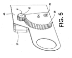
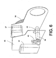
- the yarn splicing apparatus 10 further comprises a drive 27, which, as in the Figures 5 and 6 indicated via a mounted on its motor shaft 60 pinion 61 a toothed segment 38 is applied, which is rotatably mounted on a drive shaft 39.
- the drive shaft 49 which is pivotally mounted in the housing 45 of the yarn splicer 10, has at its end an operating lever 40 which is connected via a linkage 42 to a Hubkurvengetriebe 59, which ensures a defined axial positioning of the splicing prism 23.
- the sector gear 38 is in turn connected via a linkage 41 to a Hubkurvengetriebe 58 for the axial displacement of the friction rings 18, 19 of the right device side R and the lid 47 of the splicing prism 23.
- the drive shaft 39 also has a lift curve 43, on the in FIG. 8 shown laying lever 46 can be controlled for the thread separating plates.
- FIG. 7 shows in plan view the Hubkurvengetrieb 58 for axial displacement of the friction plates 18, 19 and the lid 47 of the splicing prism 23rd
- the Hubkurvengetriebe 58 has two rotatable, axially displaceably mounted, functionally non-rotatably interconnected cam elements 54, 56 and two corresponding, stationary cam members 53, 55th
- the central, tubular curve element 54 on which the cover 47 for the splicing prism 23 is arranged at the end, forms a bearing axis for a sliding sleeve 66.
- the other rotatable and axially displaceably mounted cam 56 is arranged on the sliding sleeve 66.
- a helical spring 67 which is supported on the cam element 54, holds a sunken into the sliding sleeve 66 stop ring 68 in contact with the cam member 56th Since the movable cam element 56 is supported on the stationary cam element 55, its axial position and thus also the axial position of the sliding sleeve 66 are determined by the respective angular position of the cam element 56.
- Hubkurvengetriebe 58 further has a receiving ring 48 for the outer friction ring 18 and the inner friction ring 19th
- the receiving ring 48 which has a toothing 49 on its outer periphery, is rotatably supported via a roller bearing 52, which is fixed in the housing 57 of the Hubkurvengetriebes 58.
- spring elements 50, 51 are based, which correspond to bearing rings 62, 63 for the friction rings 18, 19.
- the bearing ring 63 for the inner friction ring 18 is thereby overlapped by a claw-shaped projection on the sliding sleeve 66 and positioned by this in the axial direction.
- the positioning of the cover 47 for the splicing prism 23 takes place via the centrally arranged cam element 54, which is likewise rotatable and axially displaceably mounted.
- the cam member 54 which is rotated upon actuation of the cam member 56 and is supported on the stationary cam member 53 is pushed by the stationary cam member 53 in a predetermined axial position, by which the position of the lid 47 is defined.
- the suction nozzle 12 searches the accumulated on the cheese 15 upper thread 31, transports him to the thread splicer 10 and places it in the Fadensverlißvorraum 10th one.
- the lower thread 32 which is preferably held in a thread tensioner, picked up by the gripper tube 25 and also inserted into the Fadensverlißvorraum 10.
- upper thread 31 and lower thread 32 are aligned parallel to each other, positioned between the friction rings 16, 17 and the friction rings 18, 19 of the yarn splicing device 10 and thereby separately inserted into the winding heads 69 of the winding rollers 30.
- the outer friction ring 19 of the right device side R extended and sets, under clamping of the threads 31, 32, against the outer friction ring 17 of the left device side L of the yarn splicing device 10th
- the friction rings are rotated by the drive 26 and the reduction and transmission gear 36 in opposite directions while the threads 31, 32 prepared for the splicing process. That is, the clamped between the outer friction rings 16 and 19 threads 31 and 32 are rotated by the friction rings 16, 19 so that they are largely exempt from their Garnwindung.
- Corresponding guide pins (not shown) in the region of the friction rings 16 and 19 ensure that the parallel alignment of the threads 31, 32 is maintained during the removal of the yarn twist.
- the untwisted threads 31, 32 are centered by the guide pins in front of the splicing prism 23, which is then pushed by the drive 27 and the Hubkurvengetriebe 59 in working position and subjected to negative pressure.
- the de-twisted threads 31, 32 are thereby fixed in the prism bottom of the splicing prism 23.
- the cover 47 After closing the splicing prism 23 by the cover 47, which is effected by means of the drive 27 by corresponding application of the lifting cam gear 58, the fibers of the threads 31, 32 are pneumatically swirled by a splicing air blast.
- the splicing prism 23 moves back to its starting position.
- the resulting fiber composite is thereby clamped between the cover 47 and a pressure ring 81, which is integrated in the inner friction ring 17 on the right side of the device.
- the outer friction ring 19 of the right side of the device R is slightly withdrawn and thus released by the splicing, in the suction nozzle 12 and the gripper tube 25 fixed excess thread ends.
- the cover 47 is first moved back, and then the friction rings 18, 19 of the right-hand device side R are applied to the friction rings 16, 17 of the left-hand device side L.
- the friction rings 16-19 are then rotated so that the thread is approximately restored to its original yarn twist.
- About the inner friction rings while the torn off by the winding rollers 30 thread ends are connected to the spliced thread simultaneously.
- the friction discs are then opened and the thread released.
- the winding operation can then be continued.
Abstract
Description
Die Erfindung betrifft eine Fadenspleißvorrichtung für eine Kreuzspulen herstellende Textilmaschine gemäß dem Oberbegriff des Anspruches 1.The invention relates to a yarn splicing device for a cross-wound textile machine according to the preamble of claim 1.
Fadenspleißvorrichtungen zum knotenfreien Verbinden zweier Fäden sind in der Textilindustrie seit langem Stand der Technik und in zahlreichen Schutzrechtsanmeldungen ausführlich beschrieben. Weit verbreitet sind dabei Fadenspleißvorrichtungen, die durch pneumatisches Verwirbeln der Fäden eine nahezu garngleiche Fadenverbindung herstellen.
Im Zusammenhang mit solchen Fadenspleißvorrichtungen ist es auch bekannt, dass, um eine ordnungsgemäße Fadenverbindung herstellen zu können, die Fadenenden der zu verbindenden Fäden vor dem eigentlichen Spleißvorgang vorbereitet sein sollten.
Das heißt, die Fadenenden sollten vor dem Spleißen wenigstens teilweise von ihrer Garndrehung befreit sein.Thread splicing devices for knot-free joining two threads have long been state of the art in the textile industry and described in detail in numerous applications for protection rights. Thread splicing devices which produce a nearly yarn-like thread connection by pneumatic swirling of the threads are widely used.
In connection with such thread splicing devices, it is also known that in order to be able to produce a proper thread connection, the thread ends of the threads to be joined should be prepared before the actual splicing operation.
That is, the thread ends should be at least partially freed of their yarn twist prior to splicing.
Das Vorbereiten solcher Fadenenden für den Spleißvorgang kann dabei nach verschiedenen Methoden erfolgen.
Bei einer pneumatischen Fadenende-Vorbereitung finden in der Regel sogenannte Fadenende-Auflöseröhrchen Verwendung, während bei einer mechanischen Fadenende-Vorbereitung vorzugsweise zwei gegensinnig rotierbare Reibringe zum Einsatz kommen.The preparation of such thread ends for the splicing process can be done by various methods.
In a pneumatic yarn end preparation usually find so-called thread end-Auflöseröhrchen use, while in a mechanical yarn end preparation preferably two oppositely rotatable friction rings are used.
In der
In diese Fadenende-Auflöseröhrchen werden die Fadenenden der zu verspleißenden, abgelängten Fäden vor dem eigentlichen Spleißvorgang einsaugt und durch Einblasen eines Luftstromes, der gegen die Garndrehung der Fadenenden gerichtet ist, pneumatisch von ihrer Garndrehung befreit.
Anschließend werden die Fadenenden so in das Spleißprisma eingezogen, dass sie, parallel nebeneinander, jedoch gegenläufig ausgerichtet, im Spleißkanal des Spleißprismas positioniert sind und dort pneumatisch zu einer nahezu garngleichen Fadenverbindung verwirbelt werden können.In this thread end-Auflöseröhrchen the yarn ends of the spliced, cut to length threads are sucked in before the actual splicing and pneumatically released from their yarn rotation by blowing an air stream, which is directed against the yarn twist of the yarn ends.
Subsequently, the thread ends are drawn into the splicing prism so that they are parallel to each other, but aligned in opposite directions, positioned in the splice channel of the splicing prism and there can be pneumatically swirled to a nearly yarn-like thread connection.
Fadenspleißvorrichtungen, wie sie in der
Zu Schwierigkeiten kann es bei solchen Fadenspleißvorrichtungen allerdings kommen, wenn besondere Garne, zum Beispiel Leinengarne oder Elastangarne, gespleißt werden müssen.
Die in der Regel etwas störrischen Leinengarne lassen sich beispielsweise nur schwer in die Fadenende-Auflöseröhrchen einsaugen und sind damit vor dem eigentlichen Spleißvorgang oft nicht ordnungsgemäß vorbereitet.
Bei hochelastischen Elastangarnen besteht die Schwierigkeit, dass diese Garne oft stark zum Kringeln neigen und die Fadenenden deshalb nur sehr schwer ordnungsgemäß im Spleißkanal des Spleißprismas zu positionieren sind.Thread splicing devices, as used in the
However, such thread splicing devices may encounter difficulties when splicing special yarns, for example, linen yarns or elastane yarns.
The usually somewhat stubborn linen yarns, for example, are difficult to suck into the yarn end-Auflöseröhrchen and are therefore often not properly prepared before the actual splicing process.
In the case of highly elastic elastane yarns, there is the difficulty that these yarns often tend to curl severely and therefore the yarn ends are very difficult to position properly in the splicing channel of the splicing prism.
Durch die
Das heißt, bei der Fadenspleißvorrichtung gemäß
Mittels der begrenzt rotierbaren Reibringe wird anschließend mechanisch Garndrehung aus den zu verspleißenden Fäden herausgedreht und die vorbereiteten Fäden durch das Spleißprisma pneumatisch verbunden.
Zum Abschluss werden die in der Saugdüse bzw. im Greiferrohr gehaltenen, jetzt überschüssigen Fadenenden, der noch zwischen den Reibringen fixierten Fäden, mechanisch abgetrennt und entsorgt.That is, in the yarn splicing apparatus according to
By means of the limited rotatable friction rings, yarn twist is then mechanically removed from the threads to be spliced, and the prepared threads are pneumatically connected by the splicing prism.
Finally, held in the suction nozzle or in the gripper tube, now excess thread ends, the still fixed between the friction rings threads, mechanically separated and disposed of.
Bei der durch die
Die in der
Das bedeutet, bei jedem Partiewechsel auf der betreffenden Textilmaschine muss gegebenenfalls Fadenspleißvorrichtung für Fadenspleißvorrichtung von Hand neu eingestellt werden, was nicht nur verhältnismäßig aufwendig sondern auch sehr zeitintensiv ist.The in the
This means that at each batch change on the textile machine in question, if necessary, thread splicer for thread splicer must be readjusted by hand, which is not only relatively expensive but also very time consuming.
Fadenverbindungseinrichtungen, die gegensinnig antreibbare Reibringe aufweisen, sind auch in der
Bei diesen bekannten Fadenverbindungsvorrichtungen werden die Reibringe allerdings nicht zur Vorbereitung der Fäden eingesetzt, sondern die Fäden werden zwischen den gegensinnig antreibbaren Reibringen so beaufschlagt, dass sie miteinander verzwirnt werden.
Das heißt, diese bekannten Fadenverbindungsvorrichtungen ermöglichen zwar eine Verarbeitung auch schwer zu spleißender Garne, die mit solchen Fadenverbindungsvorrichtungen erstellten Fadenverbindungen weisen im Bereich der Fadenverbindung allerdings die doppelte Fadenmasse und damit kein garngleiches Aussehen auf.In these known yarn connecting devices, however, the friction rings are not used to prepare the threads, but the threads are so acted upon between the oppositely driven friction rings that they are twisted together.
That is, these known thread connecting devices allow processing even difficult to splice yarns, the thread connections created with such thread connecting devices have in the field of thread connection, however, twice the yarn mass and thus no yarn-like appearance.
Des weiteren sind durch die
Der als Schrittmotor ausgebildete Nuttrommelantrieb ist dabei an ein zentrales Steuersystem der Textilmaschine angeschlossen, so dass verschiedene Einstellungen aller Fadenspleißvorrichtungen von zentraler Stelle aus vorgenommen bzw. geändert werden können.
Die bekannten Fadenspleißvorrichtungen arbeiten mit pneumatischer Fadenende-Vorbereitung und sind, wie vorstehend bereits erläutert, für Garne, die schwierig zu spleißen sind, nur sehr bedingt geeignet.Furthermore, by the
Trained as a stepper motor Nuttrommelantrieb is connected to a central control system of the textile machine, so that various settings of all Fadensleiißvorrichtungen can be made or changed from a central location.
The known yarn splicing devices operate with pneumatic end-of-line preparation and are, as explained above, only of limited use for yarns which are difficult to splice.
Durch die
Die Ent- bzw. Verdrallungseinrichtungen bestehen jeweils aus einem rotierbar gelagerten, scheibenartigen Element, das eine schlitzartige Ausnehmung zum Einlegen eines Fadenendes aufweist. Die zangenartige Halte- und Zugeinrichtungen, die die Fadenenden während des Entdrallens festlegen und die Fadenenden vor dem eigentlich Spleißvorgang ablängen, sind jeweils auf den den Entdrallungseinrichtungen gegenüberliegenden Seiten des pneumatischen Spleißkopfes angeordnet.By the
The Ent- or Verdrallungseinrichtungen each consist of a rotatably mounted, disc-like element having a slot-like recess for inserting a thread end. The pincer-like holding and pulling devices which fix the thread ends during the Entdrallens and the thread ends cut to length before the actual splicing operation, respectively on the Entdrallungseinrichtungen opposite sides of the pneumatic splicing head are arranged.
Ausgehend vom vorgenannten Stand der Technik liegt der Erfindung die Aufgabe zugrunde, Fadenspleißvorrichtungen zu schaffen, die die Erstellung qualitativ hochwertiger Fadenverbindungen auch bei Garnen ermöglichen, die schwierig zu spleißen sind. Außerdem sollen die Fadenspleißvorrichtung so ausgebildet sein, dass die verschiedenen Funktionselemente dieser Fadenspleiß-vorrichtung bei Bedarf unkompliziert und schnell, vorzugsweise von zentraler Stelle aus, definiert einstellbar sind.Based on the aforementioned prior art, the present invention seeks to provide Fadensleiißvorrichtungen that allow the creation of high-quality thread connections even with yarns that are difficult to splice. In addition, the yarn splicing device should be designed so that the various functional elements of this yarn splicing device If necessary uncomplicated and fast, preferably from a central location, are defined adjustable.
Diese Aufgabe wird erfindungsgemäß durch eine Fadenspleißvorrichtung gelöst, wie sie im Anspruch 1 beschrieben ist.This object is achieved by a yarn splicing device as described in claim 1.
Vorteilhafte Ausgestaltungen der Erfindung sind Gegenstand der Unteransprüche.Advantageous embodiments of the invention are the subject of the dependent claims.
Die erfindungsgemäße Fadenspleißvorrichtung mit einem ersten Antrieb zum Positionieren einer Einrichtung zum mechanischen Vorbereiten und Nachbearbeiten der Fäden, einem zweiten Antrieb zum Betreiben dieser Einrichtung und einem dritten Antrieb zur Betätigung von Fadentrennmitteln hat den Vorteil, dass mit einer solchermaßer ausgebildeten Fadenspleißvorrichtung fast alle Arten von Garnen vorschriftsmäßig vorbereitet und anschließend nahezu garngleich verspleißt werden können, wobei gewährleistet ist, dass die zu verbindenden Fäden während des gesamten Vorbereitungs- und Spleißvorganges ständig sicher fixiert sind. Der Anschluss der Steuereinrichtungen dieser Antriebe an eine Zentralesteuereinheit der Textilmaschine hat außerdem den Vorteil, dass im Bedarfsfall, beispielsweise bei einem Partiewechsel an der Textilmaschine, über die Zentralsteuereinheit die der verschiedenen Funktionsorgane der Fadenspleißvorrichtung schnell und präzise neu eingestellt werden können. Das heißt, durch die problemlose Optimierung der Einstellungen der Fadenspleißvorrichtung ist es leicht, Fadenspleiße zu erstellen, die nicht nur eine nahezu garngleiche Optik aufweisen, sondern die auch bezüglich ihrer Festigkeit weitestgehend dem "normalen" Faden entsprechen.The yarn splicing apparatus of the present invention having a first drive for positioning a device for mechanically preparing and reworking the yarns, a second drive for operating this device, and a third drive for operating yarn separating means has the advantage that almost all kinds of yarns are properly used with such a yarn splicing device can be prepared and then spliced almost the same yarn, being sure that the threads to be connected are constantly securely fixed throughout the preparation and splicing process. The connection of the control devices of these drives to a central control unit of the textile machine also has the advantage that, if necessary, for example, a lot change on the textile machine, the central control unit of the various functional organs of the yarn splicing can be quickly and accurately reset. That is, by the easy optimization of the settings of the yarn splicing device, it is easy to create yarn splices, which not only have an almost yarn-like appearance, but also largely correspond to the "normal" thread in terms of their strength.
Die Einrichtung zum mechanischen Vorbereiten und Nachbearbeiten der Fadenenden weist als rotierbare, an einen Oberfaden und einen Unterfaden anstellbare äußere und innere Reibringe auf.The device for mechanical preparation and reworking of the thread ends has as a rotatable, to a Upper thread and a lower thread engageable outer and inner friction rings.
Die Reibringe weisen dabei zur Minimierung des Schlupfes zwischen den Reibringen und den Fäden vorzugsweise einen Reibbelag mit einem hohen Reibwert, beispielsweise aus einem gummielastischen Material, auf.
Mit derartig ausgebildeten, reversibel rotierbaren Reibringen kann bei Bedarf wahlweise Garndrehung aus den Fäden genommen oder Garndrehung auf die Fäden gegeben werden.
Das heißt, durch die beschriebenen Reibringe wird gewährleistet, dass die Fäden sowohl bei der Vorbereitung zu Beginn des Spleißvorganges als auch beim "Finishen" der Fadenverbindung zum Abschluss ordnungsgemäß bearbeitet werden.The friction rings have to minimize the slip between the friction rings and the threads preferably a friction lining with a high coefficient of friction, for example, of a rubber-elastic material on.
With such formed, reversibly rotatable friction rings, if necessary, yarn twist can be taken out of the threads or yarn twist can be applied to the threads.
That is, it is ensured by the friction rings described that the threads are properly processed both in preparation for the beginning of the splicing process as well as the "finishing" of the thread connection for completion.
Wie im Anspruch 2 beschrieben, kommen als Fadentrennmittel vorzugsweise Wickelrollen zum Einsatz.
Mit solchen Wickelrollen, die in Fadenlaufrichtung unmittelbar vor und hinter den äußeren Reibringen positioniert sind, können die sich nach dem Spleißen ergebenden, überschüssigen Fadenenden zum Beispiel auch bei Elastangarnen zuverlässig abgezogen werden.As described in
With such bobbins, which are positioned in the direction of yarn travel immediately in front of and behind the outer friction rings, the resulting after splicing, excess thread ends can be reliably deducted, for example, even with elastane yarns.
Wie im Anspruch 3 dargelegt, ist innerhalb der Reibringe der linken Vorrichtungsseite ein Spleißprisma verschiebbar gelagert, das mittels eines der vorstehend genannten Antriebe definiert positionierbar ist.
Das Spleißprisma ist dabei nach dem Einlegen und Vorbereiten der Fäden so über den zu verspleißenden Fäden positionierbar, dass in Verbindung mit einem axial verschiebbar gelagerten Deckel des Spleißprismas, der im Anspruch 4 beschrieben ist, beim Beaufschlagen des Spleißprismas mit einem Druckluftstrahl gewährleistet ist, dass eine sichere und nahezu garngleiche Fadenverbindung geschaffen wird.As set forth in
After inserting and preparing the threads, the splicing prism can be positioned over the threads to be spliced in such a way that, in conjunction with an axially displaceably mounted cover of the splicing prism, which is described in
Der Deckel des Spleißprismas ist dabei außerdem so an den inneren Reibring der linken Vorrichtungseite anlegbar (Anspr. 5), dass die gespleißten Fäden zwischen Deckel und Reibring fixiert werden.
Die freien, in die Saugdüse bzw. das Greiferrohr eingesaugten Fadenenden können auf diese Weise durch die Wickelrollen exakt an den vorgesehenen Stellen getrennt und durch die Saugdüse bzw. das Greiferrohr entsorgt werden.In this case, the cover of the splicing prism can also be applied to the inner friction ring of the left-hand device side (claim 5) so that the spliced threads are fixed between the cover and the friction ring.
The free, sucked into the suction nozzle or the gripper tube thread ends can be separated in this way by the winding rollers exactly at the intended locations and disposed of by the suction nozzle or the gripper tube.
Wie in den Ansprüchen 6 bzw. 7 beschrieben, ist über die Zentralsteuereinheit bzw. einen der vorgenannten Antriebe der Winkel der Drehung der Reibringe sowie über einen anderen dieser Antriebe das Maß des axialen Anstandes der Reibringe während der Beaufschlagung der Fäden definiert einstellbar.
Das heißt, über die Zentralsteuereinheit können, beispielsweise in Abhängigkeit vom vorliegenden Garnmaterial, sowohl der Winkel der Drehung der Reibringe als auch das Maß des axialen Anstandes der Reibringe problemlos optimiert werden.As described in
That is, via the central control unit, for example, depending on the present yarn material, both the angle of rotation of the friction rings and the degree of axial propriety of the friction rings can be easily optimized.
In vorteilhafter, im Anspruch 8 beschriebener Ausführungsform, ist außerdem vorgesehen, dass einer der Antriebe der Fadenspleißvorrichtung an ein Untersetzungs- und Übertragungsgetriebe angeschlossen ist, das so ausgebildet ist, dass bei Ansteuerung des Antriebes die Reibringe der einen Vorrichtungsseite gegensinnig zu den Reibringen der anderen Vorrichtungsseite drehen.
Auf diese Weise ist sichergestellt, dass die zwischen den Reibringen geklemmten Fäden mit einem definierten Drehmoment beaufschlagt werden, das entsprechend der Drehrichtung des zugehörigen Antriebes entweder Garndrehung aus den zu verspleißenden Fäden nimmt und die Fäden dadurch für den eigentlichen Spleißvorgang vorbereitet oder Garndrehung auf den bereits gespleißten Faden gibt.In an advantageous, described in
In this way it is ensured that the clamped between the friction rings threads are acted upon by a defined torque, which takes according to the direction of rotation of the associated drive either Garndrehung from the threads to be spliced and thereby preparing the threads for the actual splicing or Garndrehung on the already spliced Thread there.
Wie im Anspruch 9 beschrieben, ist dabei in bevorzugter Ausbildung vorgesehen, dass das Untersetzungs- und Übertragungsgetriebe über ein Ritzel direkt mit den Reibringen der linken Vorrichtungsseite korrespondiert und über eine Abtriebswelle mit einem entsprechenden Ritzel mit den Reibscheiben der rechten Vorrichtungsseite verbunden ist.
Eine solche Einrichtung baut sehr kompakt und ermöglicht es auf einfache Weise, das Antriebsmoment eines Antriebes auf zwei gegenüberliegende Vorrichtungsseiten zu verteilen und dabei gleichzeitig die Drehrichtung des Antriebsmomentes auf einer Vorrichtungsseite zu ändern.As described in
Such a device is very compact and makes it possible in a simple manner to distribute the drive torque of a drive on two opposite sides of the device while changing the direction of rotation of the drive torque on a device side.
In einer vorteilhaften, im Anspruch 10 beschriebenen Ausführungsform ist außerdem vorgesehen, dass einer der Antriebe über ein Zahnsegment drehfest mit einer Antriebswelle verbunden ist, die schwenkbeweglich im Gehäuse der Fadenspleißvorrichtung gelagert ist.In an advantageous, described in
Die Antriebswelle ist dabei über ein Gestänge mit einem Hubkurvengetriebe verbunden, das für die axiale Verlagerung des Spleißprismas sorgt, während das Zahnsegment über ein Gestänge direkt an ein Hubkurvengetriebe angeschlossen ist, das die axiale Verlagerung der Reibringe der rechten Vorrichtungsseite sowie die axiale Verlagerung des Deckels des eines Spleißprismas initiiert.
Die im Anspruch 11 beschriebenen Einrichtung ermöglicht eine definierte, zeitversetzte axiale Verlagerung unterschiedlicher Funktionsorgane der Fadenspleißvorrichtung mittels eines gemeinsamen Antriebes und stellt außerdem eine relativ kostengünstige Konstruktion dar.The drive shaft is connected via a linkage with a Hubkurvengetriebe, which provides for the axial displacement of the splicing prism, while the toothed segment is connected via a linkage directly to a Hubkurvengetriebe, the axial displacement of the friction rings of the right device side and the axial displacement of the lid of the initiated by a splicing prism.
The device described in
Das in den Ansprüchen 11 bis 16 beschriebene Hubkurvengetriebe zur axialen Verlagerung der Reibringe der rechten Vorrichtungsseite sowie des Deckels des Spleißprismas weist in vorteilhafter Ausführungsform sowohl rotierbar und axial verschiebbar gelagerte Kurvenelemente als auch stationäre Kurvenelemente auf. Auf einem der axial verschiebbar gelagerten Kurvenelemente ist außerdem eine Schiebemuffe gleitend geführt, die über einen Anschlag mit dem anderen axial verschiebbar gelagerten Kurvenelement des Hubkurvengetriebes in Verbindung steht, das seinerseits über das Gestänge an das Zahnsegment angeschlossen ist.
Zwischen die Schiebemuffe und dem als Lagerung für die Schiebemuffe dienenden axial verschiebbar gelagerten Kurvenelement ist eine Druckfeder eingeschaltet, die die Schiebemuffe beaufschlagt.The Hubkurvengetriebe described in
Between the sliding sleeve and serving as a bearing for the sliding sleeve axially displaceably mounted cam element, a compression spring is turned on, which acts on the sliding sleeve.
Die Reibringe sind über Lagerringe sowie Federelemente axial beweglich, aber drehfest in einem rotierbaren Aufnahmering angeordnet, der auf seinem Außenumfang eine Verzahnung aufweist, die mit einem Ritzel des vorgenannten Untersetzungs- und Übertragungsgetriebe kämmt.
Außerdem korrespondieren die Lagerringe mit einem krallenartigen Ansatz an der Schiebemuffe.The friction rings are axially movable via bearing rings and spring elements, but rotatably arranged in a rotatable receiving ring, which has on its outer periphery a toothing, which meshes with a pinion of the aforementioned reduction and transmission gear.
In addition, the bearing rings correspond with a claw-like approach to the sliding sleeve.
Das bedeutet, beim Verschwenken des Zahnsegmentes werden auch, die über ein Gestänge direkt oder indirekt angeschlossenen, rotierbar gelagerten Kurvenelemente gedreht, die dadurch, da sie sich an den zugehörigen stationären Kurvenelementen abstützen, axial verschoben werden.
Über die Schiebemuffe werden dann einerseits die Reibringe definiert in einer axialen Stellung positioniert und andererseits der Deckel des Spleißprismas definiert verschoben.This means that during pivoting of the toothed segment are also the connected via a linkage directly or indirectly connected, rotatably mounted cam elements rotated, thereby, since they are supported on the associated stationary cam elements, are moved axially.
On the one hand, the friction rings are defined in an axial position and on the other hand, the cover of the splicing prism defined shifted over the sliding sleeve.
Die vorbeschriebene Ausführungsform eines Hubkurvengetriebes stellt dabei eine vorteilhafte Einrichtung dar, um verschiedene Funktionsorgane einer Fadenspleißvorrichtung auf kleinstem Raum anzuordnen und diese mittels eines einzigen Antriebes gezielt axial zu verlagern.The above-described embodiment of a Hubkurvengetriebes represents an advantageous means to different functional organs of a yarn splicing device in a small space to arrange and to shift them targeted by means of a single drive axially.
Wie in den Ansprüchen 17 - 20 beschrieben, sind die als Fadentrennmittel fungierenden Wickelrollen in vorteilhafter Ausführungsform über ein Untersetzungsgetriebe an einen weiteren reversiblen Antrieb der Fadenspleißvorrichtung angeschlossen. Das Untersetzungsgetriebe ist dabei so ausgebildet, dass bei Betrieb des zugehörigen Antriebes die Wickelrollen gegensinnig rotieren und dabei zuverlässig die nach dem Spleißen vorhandenen, störenden Fadenenden abreißen.
Die Wickelrollen verfügen vorzugsweise über einen geschlitzten Wickelkopf und sind über flexible Wellen so an das Untersetzungsgetriebe angeschlossen.
Da sowohl die Geschwindigkeit mit der die Wickelrollen rotieren, als auch die Anzahl der Umdrehungen die die Wickelrollen ausführen, über die Zentralsteuereinheit einstellbar ist, lassen sich mit den Wickelrollen auch Garne mit einer elastischen Seele, sogenannte Elastangarne, problemlos verarbeiten.
Bei solchen Garnen muss lediglich die Anzahl der Umdrehungen der Wickelrollen etwas erhöht werden.As described in claims 17-20, the winding rollers acting as thread separating means are connected in an advantageous embodiment via a reduction gear to a further reversible drive of the yarn splicing device. The reduction gear is designed so that rotate the winding rollers in opposite directions during operation of the associated drive and thereby reliably demolish existing after splicing, disturbing thread ends.
The winding rollers preferably have a slotted winding head and are connected via flexible shafts to the reduction gear.
Since both the speed with which the winding rollers rotate, as well as the number of revolutions which perform the winding rollers, via the central control unit is adjustable, can be processed easily with the winding rollers and yarns with an elastic core, so-called elastane yarns.
In such yarns, only the number of revolutions of the bobbins has to be increased slightly.
Die Erfindung wird nachfolgend anhand eines in den Zeichnungen dargestellten Ausführungsbeispieles näher erläutert.The invention will be explained in more detail with reference to an embodiment shown in the drawings.
Es zeigt:
- Fig. 1
- in Seitenansicht eine Arbeitsstelle eines Kreuzspulautomaten mit einer erfindungsgemäß ausgebildeten Fadenspleißvorrichtung,
- Fig. 2
- eine erfindungsgemäße Fadenspleißvorrichtung in Draufsicht, teilweise im Schnitt,
- Fig. 3
- eine erste perspektivische Ansicht auf die Antriebseinrichtung zum Rotieren der Reibringe,
- Fig. 4
- eine zweite perspektivische Ansicht auf die Antriebseinrichtung zum Rotieren der Reibringe,
- Fig. 5
- die Fadenspleißvorrichtung mit schwenkbar gelagertem Zahnelement und zugehörigem Antrieb,
- Fig. 6
- das Gehäuse der Fadenspleißvorrichtung mit dem schwenkbar gelagerten Zahnelement, dem zugehörigem Antrieb sowie der mit dem Zahnsegment verbundenen Antriebswelle,
- Fig. 7
- eine Schnittdarstellung des Hubkurvengetriebes zur axialen Verlagerung der Reibscheiben sowie des Deckels des Spleißprismas,
- Fig. 8
- eine perspektivische Ansicht der Antriebseinrichtung für die Wickelrollen.
- Fig. 1
- a side view of a workstation of a cheese winder with a yarn splicing device according to the invention,
- Fig. 2
- a yarn splicing device according to the invention in plan view, partly in section,
- Fig. 3
- a first perspective view of the drive means for rotating the friction rings,
- Fig. 4
- a second perspective view of the drive means for rotating the friction rings,
- Fig. 5
- the thread splicing device with pivotally mounted toothed element and associated drive,
- Fig. 6
- the housing of the thread splicing device with the pivotally mounted toothed element, the associated drive and the drive shaft connected to the toothed segment,
- Fig. 7
- a sectional view of the Hubkurvengetriebes for axial displacement of the friction plates and the cover of the splicing prism,
- Fig. 8
- a perspective view of the drive means for the bobbins.
In
Derartige Kreuzspulautomaten 1 weisen zwischen ihren (nicht dargestellten) Endgestellen eine Vielzahl gleichartiger Arbeitsstellen 2 auf, auf denen, wie bekannt und daher nicht näher erläutert, Spinnkopse 9, die beispielsweise auf einer Ringspinnmaschine produziert wurden, zu großvolumigen Kreuzspulen 15 umgespult werden.
Die Kreuzspulen 15 werden nach ihrer Fertigstellung mittels eines selbsttätig arbeitenden Serviceaggregates auf eine maschinenlange Kreuzspulentransporteinrichtung 21 übergeben und zu einer maschinenendseitig angeordneten Spulenverladestation oder dergleichen transportiert.In
Such spooling machines 1 have between their (not shown) Endgestellen a plurality of
The
Solche Kreuzspulautomaten 1 weisen üblicherweise außerdem eine Logistikeinrichtung in Form eines Spulen- und Hülsentransportsystems 3 auf. In dieser Logistikeinrichtung laufen, auf Transporttellern 8 in vertikaler Ausrichtung, Spinnkopse 9, beziehungsweise Leerhülsen um.
Von diesem Spulen- und Hülsentransportsystem 3 sind in
Of this coil and
Des weiteren verfügen solche Kreuzspulautomaten 1 in der Regel über eine Zentralsteuereinheit 11, die, zum Beispiel über einen Maschinenbus 80, mit den Arbeitsstellenrechnern 29 der einzelnen Spulstellen 2 verbunden ist.Furthermore, such automatic packages 1 usually have a
Wie vorstehend bereits angedeutet, werden die angelieferten Spinnkopse 9 in den Abspulstellungen AS, die sich jeweils im Bereich der Quertransportstrecken 6 an den Spulstellen 2 befinden, zu großvolumigen Kreuzspulen 15 umgespult.As already indicated above, the delivered
Die einzelnen Spulstellen verfügen zu diesem Zweck, wie bekannt und daher nur angedeutet, über verschiedene Einrichtungen, die einen ordnungsgemäßen Betrieb dieser Arbeitsstellen
gewährleisten.
Diese Einrichtungen sind beispielsweise eine um eine Schwenkachse 13 begrenzt drehbare Saugdüse 12 zum Handhaben eines Oberfadens 31, ein um eine Schwenkachse 20 drehbares Greiferrohr 25 zum Handhaben eines Unterfadens 32 sowie eine Fadenspleißvorrichtung 10.The individual winding units have for this purpose, as is well known and therefore only indicated, various facilities that ensure the proper operation of these jobs
guarantee.
These devices are, for example, a
Wie in
Solche Arbeitsstellenstellen 2 verfügen in der Regel außerdem über weitere, nicht näher dargestellte Einrichtungen, wie einen Fadenspanner, einen Fadenreiniger, eine Paraffiniereinrichtung, eine Fadenschneideinrichtung, einen Fadenzugkraftsensor sowie einen Unterfadensensor.
Das Wickeln der Kreuzspulen 15 erfolgt auf Spulvorrichtungen 24, die unter anderem einen Spulenrahmen 28 aufweisen, der um eine Schwenkachse 22 beweglich gelagert ist und über eine Einrichtung zum drehbaren Haltern einer Kreuzspulenhülse verfügt.
Während des Spulprozesses liegt die im Spulenrahmen 28 frei drehbar gehaltene Kreuzspule 15 mit ihrer Oberfläche auf einer Spulenantriebstrommel 14 auf und wird von dieser über Reibschluss mitgenommen.The winding of the
During the winding process in the
Die erfindungsgemäße Fadenspleißvorrichtung 10 ist in den
Die
Wie ersichtlich verfügt jede dieser Fadenspleißvorrichtungen 10 über drei getrennte, reversible Antriebe 26, 27 und 33.
Die Antriebe 26, 27 und 33, vorzugsweise als Schrittmotoren ausgebildet sind, werden durch einen Arbeitsstellenrechner 29, der zum Beispiel über eine Busleitung 80 mit einer Zentralsteuereinheit 11 der Textilmaschine 1 in Verbindung steht, definiert angesteuert.
Das heißt, die Einstellparameter aller Antriebe 26, 27 und 33 sind über die Zentralsteuereinheit 11 der Textilmaschine 1 gemeinsam einstellbar.The
As can be seen, each of these
The
That is, the adjustment parameters of all drives 26, 27 and 33 are jointly adjustable via the
Der Antrieb 33 für die Wickelrollen 30 ist dabei über ein Untersetzungsgetriebe 35 an einer der Seitenwandungen des Gehäuses 45 der Fadenspleißvorrichtung 10 festgelegt.
Dieser Schrittmotor 33 treibt, wie insbesondere auch aus
Am Gehäuse des Untersetzungsgetriebes 35 ist außerdem ein Verstellhebel 46 beweglich gelagert, der (nicht dargestellte) Fadentrennbleche betätigt, die gegebenenfalls die Fäden 31 und 32 auseinanderhalten.
Der Verstellhebel 46 wird dabei durch eine an einer zentralen Antriebswelle 39 festgelegte Hubkurve 43 sowie ein zugehöriges Gestänge angesteuert.The
This stepping
On the housing of the
The adjusting
An der Seitenwandung des Gehäuses 45 der Fadenspleißvorrichtung 10, an der, wie vorstehend erläutert, das Untersetzungsgetriebe 35 des Wickelrollenantriebes festgelegt ist, ist außerdem ein Antrieb 26 befestigt, der über ein Untersetzungs- und Übertragungsgetriebe 36 die Reibringe 16 - 19 rotiert.
Der Antrieb 26 ist dabei, wie in
Während das Zahnrad 72 über ein Ritzel 74 mit der Außenverzahnung 75 eines die Reibringe 16, 17 der linken Vorrichtungsseite L aufnehmenden Aufnahmeringes 76 in Verbindung steht, ist das Zahnrad 73 über eine Abtriebswelle 37 sowie ein endseitig auf der Abtriebswelle 37 angeordnetes Ritzel 77 an die Außenverzahnung 49 eines die Reibringe 18, 19 der rechten Vorrichtungsseite R aufnehmenden Aufnahmeringes 48 angeschlossen.On the side wall of the
The
While the
Die erfindungsgemäße Fadenspleißvorrichtung 10 weist des Weiteren einen Antrieb 27 auf, der, wie in den
Die Antriebswelle 49, die schwenkbeweglich im Gehäuse 45 der Fadenspleißvorrichtung 10 gelagert ist, weist endseitig einen Bedienhebel 40 auf, der über ein Gestänge 42 an ein Hubkurvengetriebe 59 angeschlossen ist, das für eine definierte axiale Positionierung des Spleißprismas 23 sorgt.The
The
Das Zahnsegment 38 ist seinerseits über ein Gestänge 41 an ein Hubkurvengetriebe 58 zur axialen Verlagerung der Reibringe 18, 19 der rechten Vorrichtungsseite R sowie des Deckels 47 des Spleißprismas 23 angeschlossen.The
Wie in
Die
Wie angedeutet, verfügt das Hubkurvengetriebe 58 über zwei rotierbare, axial verschiebbar gelagerte, funktional drehfest miteinander verbundene Kurvenelemente 54, 56 sowie über zwei korrespondierende, stationäre Kurvenelemente 53, 55.The
As indicated, the
Das zentrale, rohrförmige Kurvenelement 54, an dem endseitig der Deckel 47 für das Spleißprisma 23 angeordnet ist, bildet dabei eine Lagerachse für eine Schiebemuffe 66.The central,
Auf der Schiebemuffe 66 ist das andere rotierbar und axial verschiebbar gelagerte Kurvenelemente 56 angeordnet.
Eine Schraubenfeder 67, die sich am Kurvenelement 54 abstützt, hält dabei einen in die Schiebemuffe 66 eingelassenen Anschlagring 68 in Anlage am Kurvenelement 56.
Da sich das bewegliche Kurvenelement 56 am stationären Kurvenelement 55 abstützt, wird durch die jeweilige Winkellage des Kurvenelementes 56 auch dessen axiale Lage und damit auch die axiale Lage der Schiebmuffe 66 bestimmt.On the sliding
A
Since the
Das Hubkurvengetriebe 58 verfügt des Weiteren über einen Aufnahmering 48 für den äußeren Reibring 18 bzw. den inneren Reibring 19.
Der Aufnahmering 48, der an seinem Außenumfang eine Verzahnung 49 aufweist, ist über ein Wälzlager 52, das im Gehäuse 57 des Hubkurvengetriebes 58 festgelegt ist, rotierbar gelagert.
Am Aufnahmering 48 stützen sich Federelemente 50, 51 ab, die mit Lagerringen 62, 63 für die Reibringe 18, 19 korrespondieren.
Der Lagerring 63 für den inneren Reibring 18 wird dabei von einem krallenförmigen Ansatz an der Schiebemuffe 66 übergriffen und von dieser in axialer Richtung positioniert.
Da der Lagerring 63 seinerseits den Lagerring 62 für den äußeren Reibring 19 übergreift, ist auch die axiale Position dieses Lagerringes 63 gegeben.
Das heißt, über die Winkelstellung des sich am stationären Kurvenelement 55 abstützenden, rotierbar und axial verschiebbar gelagerten Kurvenelementes 56 kann die axiale Position der Schiebemuffe 66 und damit auch die axiale Position der Reibringe 18, 19 exakt eingestellt werden.
The receiving
On the receiving
The bearing
Since the
That is, the axial position of the sliding
Die Positionierung des Deckels 47 für das Spleißprisma 23 erfolgt über das zentral angeordnete, ebenfalls rotierbar und axial verschiebbar gelagerte Kurvenelement 54.
Das Kurvenelement 54, das bei Betätigung des Kurvenelementes 56 mit gedreht wird und sich am stationären Kurvenelement 53 abstützt, wird durch das stationäre Kurvenelement 53 in eine vorgegebene axiale Stellung geschoben, durch die auch die Position des Deckels 47 definiert wird.The positioning of the
The
Wenn es an einer der Arbeitsstellen 2 der Textilmaschine 1 zu einer Spulunterbrechung gekommen ist, beispielsweise aufgrund eines Fadenbruches oder eines kontrollierten Reinigerschnittes, sucht die Saugdüse 12 den auf die Kreuzspule 15 aufgelaufenen Oberfaden 31, transportiert ihn zur Fadenspleißvorrichtung 10 und legt ihn in die Fadenspleißvorrichtung 10 ein.
Gleichzeitig oder nahezu gleichzeitig wird der Unterfaden 32, der vorzugsweise in einem Fadenspanner gehalten ist, durch das Greiferrohr 25 abgeholt und ebenfalls in die Fadenspleißvorrichtung 10 eingelegt.
Das heißt, Oberfaden 31 und Unterfaden 32 werden, parallel zueinander ausgerichtet, zwischen den Reibringen 16, 17 und den Reibringen 18, 19 der Fadenspleißvorrichtung 10 positioniert und dabei getrennt in die Wickelköpfe 69 der Wickelrollen 30 eingelegt.
Anschließend wird durch Inbetriebnahme des Antriebes 27 über das Zahnsegment 38 sowie das Hubkurvengetriebe 58 der äußere Reibring 19 der rechten Vorrichtungsseite R ausgefahren und legt sich, unter Klemmung der Fäden 31, 32, gegen den äußeren Reibring 17 der linken Vorrichtungsseite L der Fadenspleißvorrichtung 10.When it comes to a winding break at one of the
At the same time or almost simultaneously, the
That is,
Subsequently, by commissioning the
Im nächsten Schritt werden die Reibringe durch den Antrieb 26 sowie das Untersetzungs- und Übertragungsgetriebe 36 gegensinnig rotiert und dabei die Fäden 31, 32 für den Spleißvorgang vorbereitet.
Das heißt, die zwischen den äußeren Reibringen 16 und 19 geklemmten Fäden 31 und 32 werden durch die Reibringe 16, 19 so gedreht, dass sie weitestgehend von ihrer Garndrehung befreit sind.
Entsprechende (nicht dargestellte) Führungsstifte im Bereich der Reibringe 16 und 19 sorgen dabei dafür, dass während des Herausnehmens der Garndrehung die parallele Ausrichtung der Fäden 31, 32 erhalten bleibt.In the next step, the friction rings are rotated by the
That is, the clamped between the outer friction rings 16 and 19
Corresponding guide pins (not shown) in the region of the friction rings 16 and 19 ensure that the parallel alignment of the
Die aufgedrehten Fäden 31, 32 sind dabei durch die Führungsstifte vor dem Spleißprisma 23 zentriert, das anschließend durch den Antrieb 27 sowie das Hubkurvengetriebe 59 in Arbeitsstellung geschoben und mit Unterdruck beaufschlagt wird. Die entdrallten Fäden 31, 32 werden dadurch im Prismengrund des Spleißprismas 23 fixiert.
Nach dem Schließen des Spleißprismas 23 durch den Deckel 47, was durch entsprechende Beaufschlagung des Hubkurvengetriebes 58 mittels des Antriebes 27 erfolgt, werden die Fasern der Fäden 31, 32 durch einen Spleißluftstoß pneumatisch verwirbelt.The untwisted
After closing the
Anschließend fährt das Spleißprisma 23 in seine Ausgangsstellung zurück. Der entstandene Faserverbund wird dabei zwischen dem Deckel 47 und einem Druckring 81, der in den inneren Reibring 17 auf der rechten Vorrichtungsseite integriert ist, geklemmt. Anschließend wird der äußere Reibring 19 der rechten Vorrichtungsseite R etwas zurückgezogen und damit die durch das Spleißen entstandenen, in der Saugdüse 12 bzw. dem Greiferrohr 25 fixierten, überschüssigen Fadenenden freigegeben.Subsequently, the
Durch die Wickelrollen 30, die durch den Antrieb 33 rotiert werden, werden dann die Fadenenden im Bereich der Klemmstellen Deckel 47 / Druckring 81 abgerissen.
Die Wickelrollen 30 werden dann auf Rückwärtslauf geschaltet und die abgerissenen Fadenenden an die Saugdüse 12 bzw. das Greiferrohr 25 übergeben, die die Fadenenden entsorgen.By the winding
The
Zum Abschluss wird zunächst der Deckel 47 zurückgefahren und anschließend die Reibringe 18, 19 der rechten Vorrichtungsseite R an die Reibringe 16, 17 der linken Vorrichtungsseite L angelegt. Die Reibringe 16 - 19 werden dann so rotiert, dass der Faden in etwa wieder seine ursprüngliche Garndrehung erhält. Über die inneren Reibringe werden dabei gleichzeitig die von den Wickelrollen 30 abgerissenen Fadenenden an den gespleißten Faden angebunden.Finally, the
Die Reibscheiben werden dann geöffnet und der Faden freigegeben. Der Spulbetrieb kann anschließend fortgesetzt werden.The friction discs are then opened and the thread released. The winding operation can then be continued.
Claims (20)
- Thread splicing device for a textile machine producing cross-wound bobbins for the knot-free connection of two threads, comprising a mechanism for the mechanical preparation and finishing of the threads, a splicing prism which can be subjected to compressed air for the pneumatic intermingling of the fibres of the threads which can be inserted into a splicing channel of the splicing prism as well as mechanically operating thread separating means for detaching troublesome thread ends,
characterised in that
the mechanism for the mechanical preparation and finishing of the thread ends has rotatable outer and inner friction rings (16, 17, 18, 19) which can be set on an upper thread (31) and a lower thread (32) and in that the thread splicing device (1) has a first drive (27) for positioning the mechanism (16, 17, 18, 19) for the mechanical preparation and finishing of the threads, a second drive (26), for operating the mechanism (16, 17, 18, 19) as well as a third drive (33) for actuating the thread separating means (30) and
in that the controller of the drives (26, 27, 33) has a connection to the central control unit (11) of the textile machine (1) by means of which the movement sequences of the drives (26, 27, 33) can be centrally predetermined. - Thread splicing device according to claim 1,
characterised in that the thread separating means are configured as reversibly drivable winding rollers (30). - Thread splicing device according to claim 1,
characterised in that inside the friction rings (16, 17) of a first device side (L), the splicing prism (23) is mounted so as to be displaceable and positionable in a defined manner by means of the first drive (27). - Thread splicing device according to claim 1,
characterised in that inside the friction rings (18, 19) of the second device side (R), a lid (47) is axially displaceably arranged to close the splicing prism (23). - Thread splicing device according to claim 4,
characterised in that the lid (47) can be set on the friction ring (17) and, in this position, forms upper and lower clamping points to secure the spliced thread. - Thread splicing device according to claim 1,
characterised in that the angle of rotation of the friction rings (16, 17, 18, 19) can be adjusted in a defined manner by means of the central control unit (11) or the second drive (26). - Thread splicing device according to claim 1,
characterised in that the size of the axial spacing of the friction rings (16, 17, 18, 19) during the action upon the threads (31, 32) can be adjusted in a defined manner by means of the central control unit (11) or the first drive (27). - Thread splicing device according to claim 1,
characterised in that the second drive (26) is connected to a reduction and transmission gear unit (36), which is configured in such a way that on activation of the second drive (26), the friction rings (16, 17) of the left-hand device side (L) rotate in opposite direction to the friction rings (18, 19) of the right-hand device side (R). - Thread splicing device according to claim 8,
characterised in that the reduction and transmission gear unit (36) is connected by means of a pinion (74) to the friction rings (16, 17) of the left-hand device side (L) and by means of a drive shaft (37) and a pinion (77) to the friction rings (18, 19) of the right-hand device side (R). - Thread splicing device according to claim 1,
characterised in that the first drive (27) is connected by means of a tooth segment (38) or a drive shaft (39) non-rotationally to the tooth segment (38) both to a lifting cam gear unit (59) for the axial positioning of the splicing prism (23), and to a lifting cam gear unit (58) for the axial displacement of the friction rings (18, 19) and of the lid (47) for the splicing prism (23). - Thread splicing device according to claim 10,
characterised in that the lifting cam gear unit (58) has rotatably and axially displaceably mounted cam elements (54, 56) and stationary cam elements (53, 55). - Thread splicing device according to claim 10,
characterised in that the friction rings (18, 19) are in each case fixed on bearing rings (62 or 63), which are loaded in the axial direction by spring elements (64 or 65) and mounted in a rotatable receiving ring (48). - Thread splicing device according to claim 12,
characterised in that the axial position of the bearing rings (62 or 63) can be adjusted by means of a sliding sleeve (66). - Thread splicing device according to claim 12,
characterised in that the receiving ring (48) has teeth (49) on its outer periphery. - Thread splicing device according to claim 11,
characterised in that the sliding sleeve (66) is guided in a sliding manner on the displaceably mounted cam component (54) and in that a compression spring (67) is connected between the sliding sleeve (66) and cam component (54). - Thread splicing device according to claim 15,
characterised in that the compression spring (67) is positioned in such a way that it holds a stop (68) arranged on the sliding sleeve (66) abutting against the displaceably mounted cam component (56). - Thread splicing device according to claim 2,
characterised in that winding rollers (30) are connected to the reversible third drive (33) by means of a reduction gear unit (35). - Thread splicing device according to claim 17,
characterised in that the winding rollers (30) rotate in opposite directions on activation of the third drive (33) and in the process draw off the thread ends being produced after the splicing. - Thread splicing device according to claim 17,
characterised in that the winding rollers (30) are connected to the reduction gear unit (35) by means of flexible shafts (34). - Thread splicing device according to claim 17,
characterised in that the winding rollers (30) have a slotted winding head (69).
Applications Claiming Priority (2)
| Application Number | Priority Date | Filing Date | Title |
|---|---|---|---|
| DE200610000824 DE102006000824A1 (en) | 2006-01-05 | 2006-01-05 | Yarn splicing device for a cross-wound textile machine |
| PCT/EP2006/011357 WO2007076908A1 (en) | 2006-01-05 | 2006-11-27 | Thread splicing apparatus for a textile machine producing cross-wound bobbins |
Publications (2)
| Publication Number | Publication Date |
|---|---|
| EP1971545A1 EP1971545A1 (en) | 2008-09-24 |
| EP1971545B1 true EP1971545B1 (en) | 2010-02-10 |
Family
ID=37835199
Family Applications (1)
| Application Number | Title | Priority Date | Filing Date |
|---|---|---|---|
| EP06829142A Not-in-force EP1971545B1 (en) | 2006-01-05 | 2006-11-27 | Thread splicing apparatus for a textile machine producing cross-wound bobbins |
Country Status (4)
| Country | Link |
|---|---|
| EP (1) | EP1971545B1 (en) |
| CN (1) | CN101365639B (en) |
| DE (2) | DE102006000824A1 (en) |
| WO (1) | WO2007076908A1 (en) |
Families Citing this family (9)
| Publication number | Priority date | Publication date | Assignee | Title |
|---|---|---|---|---|
| ITMI20121019A1 (en) | 2012-06-12 | 2013-12-13 | Savio Macchine Tessili Spa | DEVICE FOR JUNCTION OF YARNS |
| DE102016123451A1 (en) * | 2016-12-05 | 2018-06-07 | Saurer Germany Gmbh & Co. Kg | yarn splicing |
| DE102019116487A1 (en) * | 2019-06-18 | 2020-12-24 | Saurer Spinning Solutions Gmbh & Co. Kg | Thread connecting device for the knot-free connection of two thread ends |
| DE102019116488A1 (en) * | 2019-06-18 | 2020-12-24 | Saurer Spinning Solutions Gmbh & Co. Kg | Thread connecting device for the knot-free connection of two thread ends |
| DE102019116481A1 (en) * | 2019-06-18 | 2020-12-24 | Saurer Spinning Solutions Gmbh & Co. Kg | Friction disks for a thread connecting device |
| DE102019116486A1 (en) * | 2019-06-18 | 2020-12-24 | Saurer Spinning Solutions Gmbh & Co. Kg | Thread connecting device for the knot-free connection of two thread ends |
| IT201900021060A1 (en) * | 2019-11-13 | 2021-05-13 | Hayabusa S R L | IMPROVEMENTS TO A TEXTILE WIRE JOINT DEVICE AND RELATED DEVICE |
| IT201900021258A1 (en) * | 2019-11-15 | 2021-05-15 | Hayabusa S R L | TEXTILE WIRE JOINT DEVICE AND RELEVANT JOINT METHOD |
| CN111519293B (en) * | 2020-05-08 | 2021-11-12 | 东华大学 | Broken yarn and head finding device based on machine vision |
Family Cites Families (16)
| Publication number | Priority date | Publication date | Assignee | Title |
|---|---|---|---|---|
| DE2851252A1 (en) * | 1978-11-27 | 1980-06-12 | Schlafhorst & Co W | Automatic splicer for broken ends on winding frame - transfers threads from above and below into pneumatic chamber |
| JPS5767466A (en) * | 1980-05-05 | 1982-04-24 | Commw Scient Ind Res Org | Method and apparatus for joining thread together |
| CS564881A2 (en) * | 1980-08-02 | 1991-02-12 | Schlafhorst & Co W | Method of textile threads connecting and entwining device for realization of this method |
| DE3029452A1 (en) * | 1980-08-02 | 1982-03-11 | W. Schlafhorst & Co, 4050 Mönchengladbach | Textile yarn splicing device - joins previously untwisted yarns, and re-twists them afterwards |
| IT1175131B (en) * | 1983-10-04 | 1987-07-01 | Savio Spa | IMPROVEMENTS TO THE WIRING JOINTS FOR THE MECHANICAL JOINTING OF TEXTILE THREADS AND MECHANICAL JOINTS ADOPTING SUCH IMPROVEMENTS |
| DE4314982B4 (en) * | 1993-05-06 | 2007-02-22 | Saurer Gmbh & Co. Kg | Method for producing a thread connection by splicing |
| DE4420979B4 (en) * | 1994-06-16 | 2005-09-01 | Saurer Gmbh & Co. Kg | Fadenendevorbereitungseinrichtung for cross-wound textile machinery manufacturing |
| IT1275947B1 (en) * | 1995-03-21 | 1997-10-24 | Mesdan Spa | APPARATUS FOR THE PNEUMATIC JOINING OF THREADS OR YARNS TO BE INSTALLED ON TEXTILE MACHINES IN PARTICULAR ON WINDING MACHINES |
| IT1275995B1 (en) * | 1995-03-31 | 1997-10-24 | Savio Macchine Tessili | PROCESS FOR JOINING TEXTILE THREADS TO RESTORE THEIR CONTINUITY IN A WINDING UNIT |
| ITMI981316A1 (en) * | 1998-06-10 | 1999-12-10 | Mesdan Spa | EQUIPMENT FOR THE PNEUMATIC JOINT OF WIRES AND WIRES TO BE INSTALLED ON TEXTILE MACHINES IN PARTICULARLY ON AUTOMATIC WINDING MACHINES |
| DE50111354D1 (en) * | 2000-12-22 | 2006-12-14 | Rieter Ag Maschf | Process for the preparation of a yarn formed in a spinning station or for piecing, as well as for the implementation of the method equipped spinning station |
| DE10150578A1 (en) * | 2001-10-12 | 2003-04-17 | Schlafhorst & Co W | yarn splicing |
| DE10224081A1 (en) * | 2002-05-31 | 2003-12-11 | Schlafhorst & Co W | Textile machine has cross-wound bobbin winding assembly with cam-operated step motor presentation of thread splicing unit |
| DE60320504T2 (en) * | 2002-10-15 | 2009-06-10 | Murata Kikai K.K. | Thread processing system |
| ITUD20040113A1 (en) | 2004-05-28 | 2004-08-28 | Gianluca Fabris | JUNCTION DEVICE AND PROCEDURE |
| DE102004042115A1 (en) * | 2004-08-30 | 2006-03-02 | Saurer Gmbh & Co. Kg | Method and device for optimizing winding and splicing parameters on a workstation of a textile machine producing cross-wound bobbins |
-
2006
- 2006-01-05 DE DE200610000824 patent/DE102006000824A1/en not_active Withdrawn
- 2006-11-27 WO PCT/EP2006/011357 patent/WO2007076908A1/en active Application Filing
- 2006-11-27 CN CN2006800491312A patent/CN101365639B/en not_active Expired - Fee Related
- 2006-11-27 DE DE502006006138T patent/DE502006006138D1/en active Active
- 2006-11-27 EP EP06829142A patent/EP1971545B1/en not_active Not-in-force
Also Published As
| Publication number | Publication date |
|---|---|
| EP1971545A1 (en) | 2008-09-24 |
| DE102006000824A1 (en) | 2007-07-12 |
| WO2007076908A1 (en) | 2007-07-12 |
| CN101365639A (en) | 2009-02-11 |
| DE502006006138D1 (en) | 2010-03-25 |
| CN101365639B (en) | 2012-01-04 |
Similar Documents
| Publication | Publication Date | Title |
|---|---|---|
| EP1971545B1 (en) | Thread splicing apparatus for a textile machine producing cross-wound bobbins | |
| EP1749906B1 (en) | Piecing arrangement for a rotor type open-end spinning machine | |
| EP1805094B1 (en) | Thread splicing device | |
| DE3802900C2 (en) | ||
| DE102011101629A1 (en) | Thread splicing device for automatic cheese winder, has smoothening zone extending over length in thread longitudinal direction, where length corresponds to thread ends projecting from channel during splicing process | |
| EP3421399A1 (en) | Thread-splicing apparatus for pneumatically connecting the ends of yarns | |
| DE102012016853A1 (en) | Method for connecting upper and lower threads at winding station of cross-winding machine, involves pivoting nozzle at thread run after head part is rotated into position, and rotating part into another position after nozzle passes run | |
| DE102016115732A1 (en) | Thread splicing device for a workstation of a cross-wound textile machine | |
| DE102008026777A1 (en) | Suction nozzle for workplace of textile machine, has movably supported cover device for partially covering suction opening, where cover device is positionably defined by suction opening and designed as swiveling cover | |
| DE4005752C2 (en) | Method and device for preparing thread ends to be spliced | |
| DE102016002695A1 (en) | Thread splicing device for a workstation of a cross-wound textile machine | |
| CH677917A5 (en) | ||
| DE102006006390A1 (en) | Thread splicing device for textile machine which produces cross-wound bobbins has rotational angle sensor for monitoring correct positioning of functional elements, and is connected to thread regulator | |
| DE102012016854A1 (en) | Method of connecting coil with winding at winding station of winding machine, involves inserting upper thread into thread link assembly, if tubular connector of suction nozzle is in thread insertion position | |
| DE102016119542A1 (en) | Thread splicing device for a workstation of a cross-wound textile machine | |
| EP1544147A2 (en) | Apparatus for splicing yarns pneumatically | |
| DE102015010844A1 (en) | Method for connecting an upper and a lower thread at a winding unit of a winding machine and winding unit of a winding machine | |
| DE102011111033A1 (en) | Thread splicing device for cross coil-producing textile machine with pneumatic loadable splicing prism in textile industry, has actuators for lower thread clamp and cutting device and upper thread clamp and cutting device | |
| EP1127831B1 (en) | Apparatus for starting a workstation of a textile machine producing cross-wound bobbins | |
| EP1076028A2 (en) | Yarn connecting device for a textile machine making cross-wound bobbins | |
| DE102018120457A1 (en) | Thread splicing device for a work station of a textile machine producing cross-wound bobbins | |
| DE102017124729A1 (en) | yarn splicing | |
| DE102017102438A1 (en) | Thread splicing device for a workstation of a cross-wound textile machine | |
| EP3321222B1 (en) | Workstation of a textile machine manufacturing cross-wound packages with a mechanical accumulator arranged in the area of the thread traversing triangle | |
| EP1302428A1 (en) | Yarn splicer |
Legal Events
| Date | Code | Title | Description |
|---|---|---|---|
| PUAI | Public reference made under article 153(3) epc to a published international application that has entered the european phase |
Free format text: ORIGINAL CODE: 0009012 |
|
| 17P | Request for examination filed |
Effective date: 20080805 |
|
| AK | Designated contracting states |
Kind code of ref document: A1 Designated state(s): CH DE IT LI |
|
| 17Q | First examination report despatched |
Effective date: 20081119 |
|
| DAX | Request for extension of the european patent (deleted) | ||
| RBV | Designated contracting states (corrected) |
Designated state(s): CH DE IT LI |
|
| GRAP | Despatch of communication of intention to grant a patent |
Free format text: ORIGINAL CODE: EPIDOSNIGR1 |
|
| GRAS | Grant fee paid |
Free format text: ORIGINAL CODE: EPIDOSNIGR3 |
|
| GRAA | (expected) grant |
Free format text: ORIGINAL CODE: 0009210 |
|
| AK | Designated contracting states |
Kind code of ref document: B1 Designated state(s): CH DE IT LI |
|
| REG | Reference to a national code |
Ref country code: CH Ref legal event code: EP |
|
| REF | Corresponds to: |
Ref document number: 502006006138 Country of ref document: DE Date of ref document: 20100325 Kind code of ref document: P |
|
| PLBE | No opposition filed within time limit |
Free format text: ORIGINAL CODE: 0009261 |
|
| STAA | Information on the status of an ep patent application or granted ep patent |
Free format text: STATUS: NO OPPOSITION FILED WITHIN TIME LIMIT |
|
| 26N | No opposition filed |
Effective date: 20101111 |
|
| PGFP | Annual fee paid to national office [announced via postgrant information from national office to epo] |
Ref country code: DE Payment date: 20101201 Year of fee payment: 5 |
|
| REG | Reference to a national code |
Ref country code: DE Ref legal event code: R119 Ref document number: 502006006138 Country of ref document: DE Effective date: 20120601 |
|
| PG25 | Lapsed in a contracting state [announced via postgrant information from national office to epo] |
Ref country code: DE Free format text: LAPSE BECAUSE OF NON-PAYMENT OF DUE FEES Effective date: 20120601 |
|
| REG | Reference to a national code |
Ref country code: CH Ref legal event code: PUE Owner name: SAURER GERMANY GMBH AND CO. KG, DE Free format text: FORMER OWNER: OERLIKON TEXTILE GMBH AND CO. KG, DE Ref country code: CH Ref legal event code: NV Representative=s name: SCHMAUDER AND PARTNER AG PATENT- UND MARKENANW, CH |
|
| REG | Reference to a national code |
Ref country code: CH Ref legal event code: PCOW Free format text: NEW ADDRESS: LEVERKUSER STRASSE 65, 42897 REMSCHEID (DE) |
|
| PGFP | Annual fee paid to national office [announced via postgrant information from national office to epo] |
Ref country code: CH Payment date: 20151123 Year of fee payment: 10 |
|
| PGFP | Annual fee paid to national office [announced via postgrant information from national office to epo] |
Ref country code: IT Payment date: 20151130 Year of fee payment: 10 |
|
| REG | Reference to a national code |
Ref country code: CH Ref legal event code: PL |
|
| PG25 | Lapsed in a contracting state [announced via postgrant information from national office to epo] |
Ref country code: CH Free format text: LAPSE BECAUSE OF NON-PAYMENT OF DUE FEES Effective date: 20161130 Ref country code: LI Free format text: LAPSE BECAUSE OF NON-PAYMENT OF DUE FEES Effective date: 20161130 |
|
| PG25 | Lapsed in a contracting state [announced via postgrant information from national office to epo] |
Ref country code: IT Free format text: LAPSE BECAUSE OF NON-PAYMENT OF DUE FEES Effective date: 20161127 |