EP1541439A1 - Systeme de transport - Google Patents
Systeme de transport Download PDFInfo
- Publication number
- EP1541439A1 EP1541439A1 EP03797598A EP03797598A EP1541439A1 EP 1541439 A1 EP1541439 A1 EP 1541439A1 EP 03797598 A EP03797598 A EP 03797598A EP 03797598 A EP03797598 A EP 03797598A EP 1541439 A1 EP1541439 A1 EP 1541439A1
- Authority
- EP
- European Patent Office
- Prior art keywords
- vehicle
- transportation system
- zone
- propulsion
- rail
- Prior art date
- Legal status (The legal status is an assumption and is not a legal conclusion. Google has not performed a legal analysis and makes no representation as to the accuracy of the status listed.)
- Granted
Links
Images

Classifications
-
- B—PERFORMING OPERATIONS; TRANSPORTING
- B61—RAILWAYS
- B61B—RAILWAY SYSTEMS; EQUIPMENT THEREFOR NOT OTHERWISE PROVIDED FOR
- B61B13/00—Other railway systems
- B61B13/12—Systems with propulsion devices between or alongside the rails, e.g. pneumatic systems
-
- B—PERFORMING OPERATIONS; TRANSPORTING
- B61—RAILWAYS
- B61B—RAILWAY SYSTEMS; EQUIPMENT THEREFOR NOT OTHERWISE PROVIDED FOR
- B61B13/00—Other railway systems
- B61B13/04—Monorail systems
-
- A—HUMAN NECESSITIES
- A63—SPORTS; GAMES; AMUSEMENTS
- A63G—MERRY-GO-ROUNDS; SWINGS; ROCKING-HORSES; CHUTES; SWITCHBACKS; SIMILAR DEVICES FOR PUBLIC AMUSEMENT
- A63G21/00—Chutes; Helter-skelters
- A63G21/04—Chutes; Helter-skelters with fixed rails
-
- B—PERFORMING OPERATIONS; TRANSPORTING
- B60—VEHICLES IN GENERAL
- B60L—PROPULSION OF ELECTRICALLY-PROPELLED VEHICLES; SUPPLYING ELECTRIC POWER FOR AUXILIARY EQUIPMENT OF ELECTRICALLY-PROPELLED VEHICLES; ELECTRODYNAMIC BRAKE SYSTEMS FOR VEHICLES IN GENERAL; MAGNETIC SUSPENSION OR LEVITATION FOR VEHICLES; MONITORING OPERATING VARIABLES OF ELECTRICALLY-PROPELLED VEHICLES; ELECTRIC SAFETY DEVICES FOR ELECTRICALLY-PROPELLED VEHICLES
- B60L13/00—Electric propulsion for monorail vehicles, suspension vehicles or rack railways; Magnetic suspension or levitation for vehicles
- B60L13/006—Electric propulsion adapted for monorail vehicles, suspension vehicles or rack railways
-
- B—PERFORMING OPERATIONS; TRANSPORTING
- B60—VEHICLES IN GENERAL
- B60N—SEATS SPECIALLY ADAPTED FOR VEHICLES; VEHICLE PASSENGER ACCOMMODATION NOT OTHERWISE PROVIDED FOR
- B60N2/00—Seats specially adapted for vehicles; Arrangement or mounting of seats in vehicles
- B60N2/02—Seats specially adapted for vehicles; Arrangement or mounting of seats in vehicles the seat or part thereof being movable, e.g. adjustable
- B60N2/20—Seats specially adapted for vehicles; Arrangement or mounting of seats in vehicles the seat or part thereof being movable, e.g. adjustable the back-rest being tiltable, e.g. to permit easy access
-
- B—PERFORMING OPERATIONS; TRANSPORTING
- B61—RAILWAYS
- B61B—RAILWAY SYSTEMS; EQUIPMENT THEREFOR NOT OTHERWISE PROVIDED FOR
- B61B1/00—General arrangement of stations, platforms, or sidings; Railway networks; Rail vehicle marshalling systems
-
- B—PERFORMING OPERATIONS; TRANSPORTING
- B61—RAILWAYS
- B61B—RAILWAY SYSTEMS; EQUIPMENT THEREFOR NOT OTHERWISE PROVIDED FOR
- B61B5/00—Elevated railway systems without suspended vehicles
-
- A—HUMAN NECESSITIES
- A63—SPORTS; GAMES; AMUSEMENTS
- A63G—MERRY-GO-ROUNDS; SWINGS; ROCKING-HORSES; CHUTES; SWITCHBACKS; SIMILAR DEVICES FOR PUBLIC AMUSEMENT
- A63G7/00—Up-and-down hill tracks; Switchbacks
-
- Y—GENERAL TAGGING OF NEW TECHNOLOGICAL DEVELOPMENTS; GENERAL TAGGING OF CROSS-SECTIONAL TECHNOLOGIES SPANNING OVER SEVERAL SECTIONS OF THE IPC; TECHNICAL SUBJECTS COVERED BY FORMER USPC CROSS-REFERENCE ART COLLECTIONS [XRACs] AND DIGESTS
- Y02—TECHNOLOGIES OR APPLICATIONS FOR MITIGATION OR ADAPTATION AGAINST CLIMATE CHANGE
- Y02T—CLIMATE CHANGE MITIGATION TECHNOLOGIES RELATED TO TRANSPORTATION
- Y02T30/00—Transportation of goods or passengers via railways, e.g. energy recovery or reducing air resistance
Definitions
- the present invention relates a transportation system for passengers or cargos, and particularly a monorail system where a small-sized, light-weighted vehicle can be used.
- monorail has been widely used as a transportation system connecting between two sites spaced by a short to middle distance (for example, 5 to 20 km) such as between residential and industrial districts or between downtown and airport.
- a short to middle distance for example, 5 to 20 km
- the monorail since a rail is supported by bridge piers constructed on the ground at a required interval, there are advantages that the degree of freedom of design of transportation route is high, and the construction cost can be saved due to a reduced land area for construction, as compared with the case of laying rails for a regular railway.
- a large drive unit is usually needed to accelerate a vehicle from a stopped condition to a required speed.
- a large drive unit is mounted in the vehicle, it leads to increases in size and weight of the vehicle. Consequently, huge bridge piers are needed to support the rail and the vehicle. This becomes a cause of lowering the degree of freedom of design with respect to the construction of a monorail system.
- the construction cost also becomes higher.
- the conventional transportation system such as monorail still has plenty of room for improvement.
- a primary concern of the present invention is to provide a transportation system having an advantage that a small-sized, light-weighted drive unit can be used as the drive unit mounted on a vehicle to achieve reductions in size and weight of the vehicle, thereby saving the cost for constructing the transportation system, and increasing the degree of freedom of design.
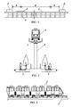
- the transportation system of the present invention for allowing the vehicle to run between stations on a track is characterized by comprising an acceleration zone for accelerating the vehicle by a propulsion supply unit provided in the vicinity of the station, and an autonomous traveling zone for allowing the vehicle accelerated in the acceleration zone to travel on the track in an autonomous manner without the propulsion supply unit.
- the vehicle since the vehicle is accelerated by the propulsion supply unit provided in the vicinity of the station, it does not need to carry a large drive unit having the capability of providing a large propulsion force to accelerate the vehicle from a stopped condition to a required speed. Consequently, remarkable reductions in size and weight of the vehicle can be achieved. Therefore, even when a sufficient land area for constructing huge bridge piers for a conventional vehicle carrying the large drive unit thereon is not secured, the transportation system of the present invention can be actualized by constructing relatively small bridges piers for the small-sized, light-weighted vehicle.
- the present invention provides an increased degree of freedom of design with respect to the construction of the transportation system. Furthermore, impossible to overlook is a considerable reduction in the construction cost.
- the propulsion supply unit of the transportation system is a linear-type accelerator for accelerating the vehicle by providing a propulsion force from a first magnet located on the track to a second magnet mounted on the vehicle.
- a linear-type accelerator for accelerating the vehicle by providing a propulsion force from a first magnet located on the track to a second magnet mounted on the vehicle.
- the propulsion supply unit is the coaster-type accelerator comprising an auxiliary track formed at an uphill gradient in the vicinity of the station, and a lifter for lifting the vehicle on the auxiliary track, which is provided such that when the vehicle lifted on the auxiliary track is released, it is accelerated by gravitation.
- the propulsion supply unit provided in the vicinity of one of the stations is the linear-type accelerator described above
- the propulsion supply unit provided in the vicinity of the other station is the coaster-type accelerator described above
- the passengers are allowed to enjoy a moderate entertainment provided by different accelerating methods in approach and backhaul routes between the stations. Therefore, this transportation system is particularly suitable to transfer the passengers in amusement parks and theme parks.
- the transportation system has a rail extending between stations and a vehicle movable on the rail and carrying a drive unit, and is characterized by comprising a first zone for accelerating the vehicle from a stopped condition to a required speed by a propulsion force supplied from the propulsion supply unit provided from one of the stations toward the other station by a predetermined distance, and a second zone not having the propulsion supply unit, in which the vehicle accelerated in the first zone travels on the rail by the propulsion force supplied from the drive unit.
- the propulsion supply unit is the linear-type accelerator for accelerating the vehicle by the propulsion force supplied from a fixed magnet located along the rail to a movable magnet mounted on the vehicle
- the drive means comprises a wheel driven by a motor mounted on the vehicle, and an auxiliary rail formed in the second zone in parallel with the rail such that the wheel travels thereon.
- a monorail system As a preferred embodiment of the transportation system of the present invention, a monorail system is explained.
- a vehicle 3 is allowed to run between stations 2 on a rail 1 as a single track supported by bridge piers 4.
- a propulsion force supplied from a propulsion supply unit which is located from one of the stations toward the other station by a predetermined distance.
- a second zone B the vehicle 3 travels by use of a drive unit mounted thereon.
- a liner-type accelerator is used as the propulsion supply unit disposed in the first zone A. That is, the rail 1 extends horizontally in the first zone A , and a fixed magnet 13 is disposed along the rail 1. The fixed magnet 13 gives the propulsion force to a movable magnet 34 mounted on the vehicle 3 to accelerate the vehicle 3 , as shown in FIG. 4.
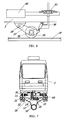
- the rail 1 is mainly composed of a main girder 10, pair of round pipe rails 11 made of a steel and disposed at upper right and left sides of the main girder 10, and a coupling member 9 for coupling between the main girder 10 and these pipe rails 11.
- the vehicle 3 has upper wheels 30, side wheels 31 and lower wheels 32, which respectively contact the pipe rails 11 from the upper, side and lower directions to be rotatable on the pipe rails 11.
- the upper wheels 30 are main wheels for supporting the weight of the vehicle 3.
- the side wheels 31 are side guide wheels.
- the lower wheels 32 are lift-off preventing wheels.
- each of the pipe rails 11 is caught by the upper, side and lower wheels (30, 31, 32), it is possible to prevent derailment of the vehicle 3 at steep slope and sharp curve locations, and ensure the safety of the transportation system.
- the upper, side and lower wheels (30, 31, 32) may be made of an elastic material such as urethane. In this case, a comfortable ride quality can be achieved by preventing vibrations of the vehicle 3 traveling on the rail 1. In addition, it is effective to prevent noise pollution.
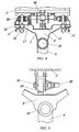
- the vehicle 3 has the drive unit for allowing the vehicle to travel in an autonomous manner.
- This drive unit is composed of a small-sized motor 36 driven by electric power, drive wheel 35 rotated by the motor 36, and a hoisting mechanism for moving the drive wheel 35 up and down.
- the hoisting mechanism comprises an arm 37, and an actuator 38 such as an air cylinder and a hydraulic cylinder used to pivot the arm 37 about a shaft 39.
- the small-sized motor 36 and the drive wheel 35 are supported by the arm 37.
- the drive wheel 35 when the drive wheel 35 is moved down by the hoisting mechanism, it contacts an upper surface of an auxiliary rail 14 provided on the top surface of the coupling member 9, so that the vehicle 3 can travel on the auxiliary rail 14 by driving the small-sized motor 36 to rotate the drive wheel 35.
- This drive unit may be formed such that after the vehicle 3 accelerated to the required speed in the first zone A comes in the second zone B and travels on the rail 1 by inertia, autonomous traveling of the vehicle 3 is actualized by contact of the drive wheel 35 with the auxiliary wheel 14 when the traveling speed becomes lower than a predetermined value.
- the numeral 50 designates a speed detector.
- the traveling speed of the vehicle 3 can be detected by a pulse signal detector or an encoder of the speed detector 50.
- a valve 51 is switched, so that the drive wheel 35 is moved down from a lifting (lift-off) position by the actuator 38 to press the drive wheel 35 against the auxiliary rail 14. Consequently, the vehicle 3 can travel on the rail 1 by a running torque of the small-sized motor 36.
- the traveling speed of the vehicle 3 is equal to or more than the predetermined value, the drive wheel 35 is left from the auxiliary rail 14 by the actuator 38, so that the vehicle 3 travels on the rail 1 by inertia force.
- the vehicle 3 can travel by inertia.
- the vehicle 3 can travel by inertia. Therefore, it is possible to save electric power consumption needed to operate the monorail system.
- a downsized motor can be used as the drive unit mounted on the vehicle in the monorail system of the present invention. As a result, it is possible to achieve remarkable reductions in size and weight of the vehicle.
- the numeral 17 designates a power supply unit for the vehicle 3.
- This power supply unit 17 is provided on the coupling member 9, and electric power can be supplied to the vehicle through a current collector (not shown) of the vehicle.
- a current collector not shown
- the electric power supply unit 17 is located on the rail 1 in the station area, and a battery (not shown) is mounted on the vehicle 3, the battery can be charged through the current collector at the stopped condition.
- an interior light or an air conditioner may be operated by using the electric power supplied from the charged battery.
- a braking device of the vehicle 3 of the present embodiment comprises a brake plate 60 provided at a lower portion of the vehicle 3, and a brake unit 15 provided on the top surface of the coupling member 9.
- the brake unit 15 has a pair of brake pads 16 for stopping the vehicle 3 by sandwiching the brake plate 60 therebetween.
- the braking device is not limited to this embodiment. For example, a downsized motor with a brake, or a brake attached to the drive wheel 35 may be used.
- the vehicle 3 has a flat floor designed in a barrier free manner. In this case, it is possible to prevent a situation that the passenger stumbles in the vehicle, and improve the safety of the monorail system. In addition, since children and elder people can safely ride on the vehicle, there is a further advantage of expanding the age group of passengers using the transportation system.
- the monorail system having the first zone A, in which the linear-type accelerator is provided in the vicinity of the respective station 2 was explained.
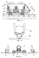
- the monorail system of the present embodiment is substantially the same as that of the first embodiment except that the first zone A using the linear-type accelerator is formed in the vicinity of one of the stations 20, and a third zone C using a coaster-type accelerator is formed in the vicinity of the other station 21 as the propulsion supplying unit other than the linear-type accelerator. Therefore, duplicate explanations are omitted.
- the coaster-type accelerator of this embodiment is mainly composed of an additional rail 100 formed at an uphill gradient in the vicinity of the station, and a lifting device (not shown) fixed at a top end of the additional rail.
- the lifting device comprises a motor with reduction gears and a chain.
- the lifting device may be formed with a rope, winding unit, motor with reduction gears, and an elevating table.
- the vehicle 3 is allowed to run between the stations (20, 21), as described below. That is, when the vehicle 3 travels from the station 20 toward the station 21 , it is accelerated from a stopped condition at the station 20 to a desired traveling speed by the linear-type accelerator of the first zone A. Then, the accelerated vehicle travels in the second zone B by use of the drive unit mounted on the vehicle so as to maintain the traveling speed.
- the traveling speed of the accelerated vehicle is equal to or greater than a predetermined value in the second zone B
- the vehicle 3 may travel by inertia. When the traveling speed becomes smaller than the predetermined value, the vehicle travels by use of the drive unit mounted thereon. As a result, the vehicle 3 arrives at the station 21 through the second zone B .
- the vehicle 3 travels from the station 21 toward the station 20, the vehicle 3 is lifted up along the additional rail 100 in the third zone C.
- the vehicle reaches a required height, it is released from the lifting device, so that the vehicle 3 glides down the additional rail 100.
- the vehicle is accelerated to the required speed by gravitation and then comes in the second zone B.
- the accelerated vehicle travels in the second zone B in the same manner as the case of allowing the vehicle 3 to travel from the station 20 to the station 21 . Consequently, the vehicle arrives at the station 20 through the second zone B .
- the first zone A functions as an extension of the second zone B rather than the acceleration zone.
- the downside space of the additional rail 100 in the third zone C can be effectively used as a carriageway or a sidewalk.
- this transportation system is preferable to transport the passengers to an amusement park, or between attractions in the amusement park.
- the third zone C of coaster-type accelerator may be formed at the vicinity of the station 20 in place of the first zone A of the linear-type accelerator.
- the vehicle 3 is placed on the slope of the additional rail 100. Therefore, from the viewpoint of achieving a safe and comfortable transportation of the passengers, it is preferred to use a seat posture controller for stably holding the passengers on seats in the vehicle.
- This controller comprises seats (70, 71) pivotally movable in the vehicle, gravity detector 76 for detecting a direction of gravity, and a seat angle adjuster 74 controlled according to an output of the gravity detector 76.
- the seat 70 is pivotally supported about a fulcrum 72 at a position higher than a center of gravity of the passenger on the seat, e.g., at substantially a shoulder position of the passenger on the seat 70.
- the seat angle adjuster 74 has a fluid power cylinder or a damper, which is disposed in a space between the seat 70 and the vehicle's floor.
- the center seat 70 is configured in an inverted T-shape, and supported to be pivotally movable against the floor, as shown by the solid and dotted lines in FIG. 11.
- one side of the seat 70 is used for the passengers that face toward the traveling direction, and the other side of the seat 70 is used for the passengers that face toward the opposite direction.
- the seat surface can be always maintained to be substantially perpendicular to the direction of gravity. Therefore, the seat can stably receive the weight of the passenger to provide a comfortable ride quality to the passenger.
- This seat posture control unit may be used in the transportation system not having the third zone C of the present invention.
- the transportation system of the present invention comprises a position adjuster 80 of a backrest 75 of the seat.
- this adjuster it is allowed for the passengers on the seat to face toward the traveling direction. Therefore, even when the vehicle is suddenly accelerated in the traveling direction, the weight of the passenger is stably received by the backrest, so that the passengers can get the comfortable ride quality.
- the transportation system is excellent in compatibility with the surrounding environment.
- the rail 1 can be supported by bridge piers 4 having an increased height, which are constructed at a center portion of an existing sidewalk 5.
- the rail 1 may be supported by another bridge piers 4 having a small height, which are constructed at a center divider between adjacent existing carriageways 6.
- the transportation system of the present invention can be constructed under a high degree of freedom of design.
- the present invention provides a near-future type of transportation system for safely and comfortably transferring passengers with the advantages of pollution-free and energy conservation, and therefore it is hopefully expected as a new traffic system in urban developments actively performed at landfill sites in recent years.
- the transportation system is constructed at an expensive location, the construction cost can be remarkably saved due to a reduced land area for the construction.
- the transportation system of the present invention is used to transfer passengers in amusement parks and theme parks, it is possible to provide a moderate entertainment to the passengers by the acceleration zone using the above-described coaster-type accelerator.
- the present invention is expected to be utilized as the transportation system for connecting between residential and industrial districts or between downtown and airport, which are spaced from each other by a short to middle distance, transportation system for the passengers in the amusement parks and the theme parks, and as the new traffic system in the urban developments for the next generation.
Landscapes
- Engineering & Computer Science (AREA)
- Transportation (AREA)
- Mechanical Engineering (AREA)
- Chemical & Material Sciences (AREA)
- Combustion & Propulsion (AREA)
- Physics & Mathematics (AREA)
- Power Engineering (AREA)
- Electromagnetism (AREA)
- Aviation & Aerospace Engineering (AREA)
- Motorcycle And Bicycle Frame (AREA)
- Platform Screen Doors And Railroad Systems (AREA)
- Electric Propulsion And Braking For Vehicles (AREA)
- Threshing Machine Elements (AREA)
- Control Of Vehicles With Linear Motors And Vehicles That Are Magnetically Levitated (AREA)
Applications Claiming Priority (3)
| Application Number | Priority Date | Filing Date | Title |
|---|---|---|---|
| JP2002270653A JP3867035B2 (ja) | 2002-09-17 | 2002-09-17 | 人員輸送システム |
| JP2002270653 | 2002-09-17 | ||
| PCT/JP2003/011749 WO2004026654A1 (fr) | 2002-09-17 | 2003-09-12 | Systeme de transport |
Publications (3)
| Publication Number | Publication Date |
|---|---|
| EP1541439A1 true EP1541439A1 (fr) | 2005-06-15 |
| EP1541439A4 EP1541439A4 (fr) | 2005-12-21 |
| EP1541439B1 EP1541439B1 (fr) | 2008-05-21 |
Family
ID=32024833
Family Applications (1)
| Application Number | Title | Priority Date | Filing Date |
|---|---|---|---|
| EP03797598A Expired - Lifetime EP1541439B1 (fr) | 2002-09-17 | 2003-09-12 | Systeme de transport |
Country Status (12)
| Country | Link |
|---|---|
| US (1) | US7162959B2 (fr) |
| EP (1) | EP1541439B1 (fr) |
| JP (1) | JP3867035B2 (fr) |
| KR (1) | KR100719032B1 (fr) |
| CN (1) | CN100411926C (fr) |
| AT (1) | ATE396095T1 (fr) |
| AU (1) | AU2003261603A1 (fr) |
| DE (1) | DE60321191D1 (fr) |
| ES (1) | ES2305561T3 (fr) |
| HK (1) | HK1077788A1 (fr) |
| TW (1) | TWI239301B (fr) |
| WO (1) | WO2004026654A1 (fr) |
Cited By (1)
| Publication number | Priority date | Publication date | Assignee | Title |
|---|---|---|---|---|
| WO2021069764A1 (fr) | 2019-10-09 | 2021-04-15 | Hernandez Herrero Juan | Système pour la propulsion d'un objet mobile au moyen d'impulsions magnétiques |
Families Citing this family (30)
| Publication number | Priority date | Publication date | Assignee | Title |
|---|---|---|---|---|
| US7610861B1 (en) * | 2005-11-07 | 2009-11-03 | Colclasure William J | Magnetic and inertial propulsion system |
| DE102006054116B3 (de) * | 2006-11-15 | 2008-04-17 | Mack Rides Gmbh & Co Kg | Schienengebundenes Fahrzeug für ein Vergnügungsfahrgeschäft |
| JP5189774B2 (ja) * | 2007-02-20 | 2013-04-24 | 泉陽興業株式会社 | 軌道車両の制動エネルギ回収装置および輸送システム |
| EP1988122A1 (fr) * | 2007-05-04 | 2008-11-05 | Total Petrochemicals Research Feluy | Mélange à utiliser dans une application automobile |
| JP2009280030A (ja) * | 2008-05-21 | 2009-12-03 | Senyo Kiko Kk | 乗物装置 |
| CA2724891C (fr) | 2008-05-23 | 2017-07-11 | Thyssenkrupp Elevator Capital Corporation | Systeme de guidage et d'equilibrage actif pour ascenseur |
| JP5685023B2 (ja) * | 2010-08-19 | 2015-03-18 | 泉陽興業株式会社 | 輸送システム |
| CN101992784A (zh) * | 2010-10-20 | 2011-03-30 | 叶高峰 | 一种新型轨道交通方法及其系统 |
| KR101307742B1 (ko) * | 2011-11-16 | 2013-09-11 | 한국철도기술연구원 | 가감속 구간 또는 초고속 구간에서의 선형전동기를 이용한 철도차량 시스템 |
| EP2792394B1 (fr) * | 2013-04-16 | 2016-07-27 | Jörg Beutler | Commande de vitesse interactive |
| CN103273926A (zh) * | 2013-05-02 | 2013-09-04 | 翁志远 | 高原与丘陵山区最佳运输法天梯运输体系 |
| US9108584B2 (en) | 2013-11-20 | 2015-08-18 | Ford Global Technologies, Llc | Multi-stage airbag in vehicle with reconfigurable interior |
| US9580033B2 (en) | 2013-11-20 | 2017-02-28 | Ford Global Technologies, Llc | Dual airbags in vehicle with reconfigurable interior |
| US9227531B2 (en) | 2013-11-20 | 2016-01-05 | Ford Global Technologies, Llc | Autonomous vehicle with reconfigurable seats |
| US9073574B2 (en) * | 2013-11-20 | 2015-07-07 | Ford Global Technologies, Llc | Autonomous vehicle with reconfigurable interior |
| DE102014223192A1 (de) * | 2013-11-20 | 2015-05-21 | Ford Global Technologies, Llc | Autonomes Fahrzeug mit rekonfigurierbaren Sitzen |
| US9199553B2 (en) | 2013-11-20 | 2015-12-01 | Ford Global Technologies | Autonomous vehicle with reconfigurable seats |
| US9096150B2 (en) * | 2013-11-20 | 2015-08-04 | Ford Global Technologies, Llc | Autonomous vehicle with reconfigurable seats |
| US9526997B2 (en) * | 2014-07-22 | 2016-12-27 | Universal City Studios Llc | Vehicle transportation room system and method |
| CN104401334A (zh) * | 2014-10-27 | 2015-03-11 | 华东交通大学 | 一种可在山地斜坡之间实现运输和搭载综合作业的新装置 |
| US10099149B2 (en) * | 2015-10-02 | 2018-10-16 | Universal City Studios Llc | Amusement park ride tunnel |
| CN105620495A (zh) * | 2016-01-28 | 2016-06-01 | 北京九州动脉隧道技术有限公司 | 一种用于真空管道列车的阶段式驱动系统 |
| CN106314458B (zh) * | 2016-08-26 | 2018-06-05 | 张英华 | 高铁列车的地效行驶接站车及追逐式接站方法 |
| CN106740876A (zh) * | 2017-02-20 | 2017-05-31 | 夏彤宇 | 一种时速同步动态密集编解组连续运输方法 |
| CN107054384B (zh) * | 2017-06-11 | 2023-08-25 | 山西科达自控股份有限公司 | 一种4g巡检机器人及巡检系统 |
| CN107972528B (zh) * | 2017-12-26 | 2023-06-30 | 北京首旺科技有限公司 | 一种超导磁悬浮天街有轨交通工具 |
| CN108909769A (zh) * | 2018-08-22 | 2018-11-30 | 王成帅 | 一种分散站台式列车运行系统 |
| US10625656B1 (en) * | 2019-06-04 | 2020-04-21 | W. Brian Golden | System and method for enhancing fan experience when attending a sporting event such as a football game or a music concert at a stadium |
| WO2021224978A1 (fr) * | 2020-05-08 | 2021-11-11 | 泉陽興業株式会社 | Système de transport |
| CN113022594A (zh) * | 2021-04-06 | 2021-06-25 | 四川省青云智创超轻型智慧轨道交通技术研发中心(有限合伙) | 一种超轻型轨道交通线路系统 |
Citations (4)
| Publication number | Priority date | Publication date | Assignee | Title |
|---|---|---|---|---|
| DE3840224A1 (de) * | 1987-12-07 | 1989-06-22 | Miklos Tempinszky | Bahn fuer verkehrsmittel, insbesondere fuer stadtbahnen zum beispiel fuer metros |
| WO1998045007A1 (fr) * | 1997-04-04 | 1998-10-15 | Vekoma Technology B.V. | Manege comprenant un chariot pouvant se deplacer sur un rail |
| US20010015148A1 (en) * | 1996-06-11 | 2001-08-23 | Mckoy Errol W. | Watercraft amusement ride |
| EP1172273A1 (fr) * | 2000-07-14 | 2002-01-16 | Senyo Kogyo Co., Ltd. | Système de transport de passager |
Family Cites Families (11)
| Publication number | Priority date | Publication date | Assignee | Title |
|---|---|---|---|---|
| JPS6012739B2 (ja) | 1980-06-06 | 1985-04-03 | 日本電子株式会社 | 走査電子顕微鏡等用対物レンズ |
| JPS5966659A (ja) | 1982-10-08 | 1984-04-16 | Kubota Ltd | 強制循環式太陽熱利用液加熱装置 |
| JPS6099286A (ja) | 1984-09-26 | 1985-06-03 | 泉陽機工株式会社 | 娯楽用乗物の走行方法 |
| JPS61218447A (ja) * | 1985-03-25 | 1986-09-27 | Hitachi Ltd | 転換シ−ト |
| JPS6315084A (ja) | 1986-07-07 | 1988-01-22 | 株式会社 タクマ | ロ−タリキルンのクリンカ除去装置 |
| JPS6322275A (ja) | 1986-07-14 | 1988-01-29 | Nachi Fujikoshi Corp | ダイヤモンド電着ワイヤ又はリボン |
| JP3735144B2 (ja) * | 1995-08-11 | 2006-01-18 | 天龍工業株式会社 | ロング・クロス配列切替式乗物用座席群 |
| US6182576B1 (en) * | 1996-05-07 | 2001-02-06 | Einar Svensson | Monorail system |
| US6024647A (en) * | 1998-06-24 | 2000-02-15 | Universal Studios, Inc. | Amusement ride vehicle with motion controlled seating |
| US6363857B1 (en) * | 2000-06-07 | 2002-04-02 | John Kauffman | Transportation system |
| JP4334774B2 (ja) * | 2001-02-08 | 2009-09-30 | 財団法人鉄道総合技術研究所 | リニアモーターカーの駆動推進制御システム |
-
2002
- 2002-09-17 JP JP2002270653A patent/JP3867035B2/ja not_active Expired - Lifetime
-
2003
- 2003-09-12 CN CNB03821945XA patent/CN100411926C/zh not_active Expired - Lifetime
- 2003-09-12 WO PCT/JP2003/011749 patent/WO2004026654A1/fr active IP Right Grant
- 2003-09-12 US US10/528,122 patent/US7162959B2/en not_active Expired - Fee Related
- 2003-09-12 AU AU2003261603A patent/AU2003261603A1/en not_active Abandoned
- 2003-09-12 EP EP03797598A patent/EP1541439B1/fr not_active Expired - Lifetime
- 2003-09-12 DE DE60321191T patent/DE60321191D1/de not_active Expired - Lifetime
- 2003-09-12 ES ES03797598T patent/ES2305561T3/es not_active Expired - Lifetime
- 2003-09-12 KR KR1020057004476A patent/KR100719032B1/ko not_active IP Right Cessation
- 2003-09-12 AT AT03797598T patent/ATE396095T1/de not_active IP Right Cessation
- 2003-09-16 TW TW092125457A patent/TWI239301B/zh not_active IP Right Cessation
-
2005
- 2005-11-01 HK HK05109722A patent/HK1077788A1/xx not_active IP Right Cessation
Patent Citations (4)
| Publication number | Priority date | Publication date | Assignee | Title |
|---|---|---|---|---|
| DE3840224A1 (de) * | 1987-12-07 | 1989-06-22 | Miklos Tempinszky | Bahn fuer verkehrsmittel, insbesondere fuer stadtbahnen zum beispiel fuer metros |
| US20010015148A1 (en) * | 1996-06-11 | 2001-08-23 | Mckoy Errol W. | Watercraft amusement ride |
| WO1998045007A1 (fr) * | 1997-04-04 | 1998-10-15 | Vekoma Technology B.V. | Manege comprenant un chariot pouvant se deplacer sur un rail |
| EP1172273A1 (fr) * | 2000-07-14 | 2002-01-16 | Senyo Kogyo Co., Ltd. | Système de transport de passager |
Non-Patent Citations (1)
| Title |
|---|
| See also references of WO2004026654A1 * |
Cited By (1)
| Publication number | Priority date | Publication date | Assignee | Title |
|---|---|---|---|---|
| WO2021069764A1 (fr) | 2019-10-09 | 2021-04-15 | Hernandez Herrero Juan | Système pour la propulsion d'un objet mobile au moyen d'impulsions magnétiques |
Also Published As
| Publication number | Publication date |
|---|---|
| US7162959B2 (en) | 2007-01-16 |
| ES2305561T3 (es) | 2008-11-01 |
| EP1541439B1 (fr) | 2008-05-21 |
| CN1681695A (zh) | 2005-10-12 |
| TW200404689A (en) | 2004-04-01 |
| KR100719032B1 (ko) | 2007-05-16 |
| US20060042497A1 (en) | 2006-03-02 |
| ATE396095T1 (de) | 2008-06-15 |
| DE60321191D1 (de) | 2008-07-03 |
| TWI239301B (en) | 2005-09-11 |
| EP1541439A4 (fr) | 2005-12-21 |
| JP2004106666A (ja) | 2004-04-08 |
| WO2004026654A1 (fr) | 2004-04-01 |
| AU2003261603A1 (en) | 2004-04-08 |
| JP3867035B2 (ja) | 2007-01-10 |
| KR20050044804A (ko) | 2005-05-12 |
| HK1077788A1 (en) | 2006-02-24 |
| CN100411926C (zh) | 2008-08-20 |
Similar Documents
| Publication | Publication Date | Title |
|---|---|---|
| US7162959B2 (en) | Transportation system | |
| JP3510196B2 (ja) | 人員輸送装置 | |
| AU769394B2 (en) | Monorail system | |
| KR100866003B1 (ko) | 전자 제어 시스템을 갖춘 모노레일 시스템 | |
| JP5756095B2 (ja) | 懸垂式車両用の軌道及びボギー台車 | |
| EP1673269B1 (fr) | Systeme de transport | |
| JP2004535321A5 (fr) | ||
| JP3679108B2 (ja) | デュアルモード車両、デュアルモード車両の走行方法、走行モード変換用構造体及びデュアルモード交通システム | |
| CN211032545U (zh) | 高效无停歇运行公共交通系统 | |
| KR100459973B1 (ko) | 인원 수송장치 | |
| EP1726503A2 (fr) | Système ferroviaire à monorail |
Legal Events
| Date | Code | Title | Description |
|---|---|---|---|
| PUAI | Public reference made under article 153(3) epc to a published international application that has entered the european phase |
Free format text: ORIGINAL CODE: 0009012 |
|
| 17P | Request for examination filed |
Effective date: 20050309 |
|
| AK | Designated contracting states |
Kind code of ref document: A1 Designated state(s): AT BE BG CH CY CZ DE DK EE ES FI FR GB GR HU IE IT LI LU MC NL PT RO SE SI SK TR |
|
| AX | Request for extension of the european patent |
Extension state: AL LT LV MK |
|
| A4 | Supplementary search report drawn up and despatched |
Effective date: 20051108 |
|
| RIC1 | Information provided on ipc code assigned before grant |
Ipc: 7B 61B 13/12 B Ipc: 7B 61B 1/00 A Ipc: 7A 63G 7/00 B |
|
| DAX | Request for extension of the european patent (deleted) | ||
| REG | Reference to a national code |
Ref country code: HK Ref legal event code: DE Ref document number: 1077788 Country of ref document: HK |
|
| 17Q | First examination report despatched |
Effective date: 20060905 |
|
| GRAP | Despatch of communication of intention to grant a patent |
Free format text: ORIGINAL CODE: EPIDOSNIGR1 |
|
| GRAS | Grant fee paid |
Free format text: ORIGINAL CODE: EPIDOSNIGR3 |
|
| GRAA | (expected) grant |
Free format text: ORIGINAL CODE: 0009210 |
|
| AK | Designated contracting states |
Kind code of ref document: B1 Designated state(s): AT BE BG CH CY CZ DE DK EE ES FI FR GB GR HU IE IT LI LU MC NL PT RO SE SI SK TR |
|
| REG | Reference to a national code |
Ref country code: GB Ref legal event code: FG4D |
|
| REG | Reference to a national code |
Ref country code: CH Ref legal event code: EP |
|
| REF | Corresponds to: |
Ref document number: 60321191 Country of ref document: DE Date of ref document: 20080703 Kind code of ref document: P |
|
| REG | Reference to a national code |
Ref country code: IE Ref legal event code: FG4D |
|
| PG25 | Lapsed in a contracting state [announced via postgrant information from national office to epo] |
Ref country code: SI Free format text: LAPSE BECAUSE OF FAILURE TO SUBMIT A TRANSLATION OF THE DESCRIPTION OR TO PAY THE FEE WITHIN THE PRESCRIBED TIME-LIMIT Effective date: 20080521 |
|
| PG25 | Lapsed in a contracting state [announced via postgrant information from national office to epo] |
Ref country code: FI Free format text: LAPSE BECAUSE OF FAILURE TO SUBMIT A TRANSLATION OF THE DESCRIPTION OR TO PAY THE FEE WITHIN THE PRESCRIBED TIME-LIMIT Effective date: 20080521 |
|
| REG | Reference to a national code |
Ref country code: ES Ref legal event code: FG2A Ref document number: 2305561 Country of ref document: ES Kind code of ref document: T3 |
|
| PGFP | Annual fee paid to national office [announced via postgrant information from national office to epo] |
Ref country code: AT Payment date: 20080912 Year of fee payment: 6 |
|
| REG | Reference to a national code |
Ref country code: HK Ref legal event code: GR Ref document number: 1077788 Country of ref document: HK |
|
| PG25 | Lapsed in a contracting state [announced via postgrant information from national office to epo] |
Ref country code: CZ Free format text: LAPSE BECAUSE OF FAILURE TO SUBMIT A TRANSLATION OF THE DESCRIPTION OR TO PAY THE FEE WITHIN THE PRESCRIBED TIME-LIMIT Effective date: 20080521 Ref country code: SE Free format text: LAPSE BECAUSE OF FAILURE TO SUBMIT A TRANSLATION OF THE DESCRIPTION OR TO PAY THE FEE WITHIN THE PRESCRIBED TIME-LIMIT Effective date: 20080821 Ref country code: PT Free format text: LAPSE BECAUSE OF FAILURE TO SUBMIT A TRANSLATION OF THE DESCRIPTION OR TO PAY THE FEE WITHIN THE PRESCRIBED TIME-LIMIT Effective date: 20081021 Ref country code: DK Free format text: LAPSE BECAUSE OF FAILURE TO SUBMIT A TRANSLATION OF THE DESCRIPTION OR TO PAY THE FEE WITHIN THE PRESCRIBED TIME-LIMIT Effective date: 20080521 |
|
| PGFP | Annual fee paid to national office [announced via postgrant information from national office to epo] |
Ref country code: CH Payment date: 20081002 Year of fee payment: 6 |
|
| PG25 | Lapsed in a contracting state [announced via postgrant information from national office to epo] |
Ref country code: RO Free format text: LAPSE BECAUSE OF FAILURE TO SUBMIT A TRANSLATION OF THE DESCRIPTION OR TO PAY THE FEE WITHIN THE PRESCRIBED TIME-LIMIT Effective date: 20080521 Ref country code: SK Free format text: LAPSE BECAUSE OF FAILURE TO SUBMIT A TRANSLATION OF THE DESCRIPTION OR TO PAY THE FEE WITHIN THE PRESCRIBED TIME-LIMIT Effective date: 20080521 |
|
| PGFP | Annual fee paid to national office [announced via postgrant information from national office to epo] |
Ref country code: BE Payment date: 20080922 Year of fee payment: 6 |
|
| PLBE | No opposition filed within time limit |
Free format text: ORIGINAL CODE: 0009261 |
|
| STAA | Information on the status of an ep patent application or granted ep patent |
Free format text: STATUS: NO OPPOSITION FILED WITHIN TIME LIMIT |
|
| 26N | No opposition filed |
Effective date: 20090224 |
|
| PG25 | Lapsed in a contracting state [announced via postgrant information from national office to epo] |
Ref country code: MC Free format text: LAPSE BECAUSE OF NON-PAYMENT OF DUE FEES Effective date: 20080930 Ref country code: BG Free format text: LAPSE BECAUSE OF FAILURE TO SUBMIT A TRANSLATION OF THE DESCRIPTION OR TO PAY THE FEE WITHIN THE PRESCRIBED TIME-LIMIT Effective date: 20080821 Ref country code: EE Free format text: LAPSE BECAUSE OF FAILURE TO SUBMIT A TRANSLATION OF THE DESCRIPTION OR TO PAY THE FEE WITHIN THE PRESCRIBED TIME-LIMIT Effective date: 20080521 |
|
| PG25 | Lapsed in a contracting state [announced via postgrant information from national office to epo] |
Ref country code: IE Free format text: LAPSE BECAUSE OF NON-PAYMENT OF DUE FEES Effective date: 20080912 |
|
| BERE | Be: lapsed |
Owner name: SENYO KOGYO CO., LTD. Effective date: 20090930 |
|
| REG | Reference to a national code |
Ref country code: CH Ref legal event code: PL |
|
| PG25 | Lapsed in a contracting state [announced via postgrant information from national office to epo] |
Ref country code: AT Free format text: LAPSE BECAUSE OF NON-PAYMENT OF DUE FEES Effective date: 20090912 |
|
| PG25 | Lapsed in a contracting state [announced via postgrant information from national office to epo] |
Ref country code: LU Free format text: LAPSE BECAUSE OF NON-PAYMENT OF DUE FEES Effective date: 20080912 Ref country code: HU Free format text: LAPSE BECAUSE OF FAILURE TO SUBMIT A TRANSLATION OF THE DESCRIPTION OR TO PAY THE FEE WITHIN THE PRESCRIBED TIME-LIMIT Effective date: 20081122 Ref country code: CY Free format text: LAPSE BECAUSE OF FAILURE TO SUBMIT A TRANSLATION OF THE DESCRIPTION OR TO PAY THE FEE WITHIN THE PRESCRIBED TIME-LIMIT Effective date: 20080521 |
|
| PG25 | Lapsed in a contracting state [announced via postgrant information from national office to epo] |
Ref country code: TR Free format text: LAPSE BECAUSE OF FAILURE TO SUBMIT A TRANSLATION OF THE DESCRIPTION OR TO PAY THE FEE WITHIN THE PRESCRIBED TIME-LIMIT Effective date: 20080521 Ref country code: BE Free format text: LAPSE BECAUSE OF NON-PAYMENT OF DUE FEES Effective date: 20090930 |
|
| PG25 | Lapsed in a contracting state [announced via postgrant information from national office to epo] |
Ref country code: GR Free format text: LAPSE BECAUSE OF FAILURE TO SUBMIT A TRANSLATION OF THE DESCRIPTION OR TO PAY THE FEE WITHIN THE PRESCRIBED TIME-LIMIT Effective date: 20080822 Ref country code: CH Free format text: LAPSE BECAUSE OF NON-PAYMENT OF DUE FEES Effective date: 20090930 Ref country code: LI Free format text: LAPSE BECAUSE OF NON-PAYMENT OF DUE FEES Effective date: 20090930 |
|
| REG | Reference to a national code |
Ref country code: FR Ref legal event code: PLFP Year of fee payment: 14 |
|
| PGFP | Annual fee paid to national office [announced via postgrant information from national office to epo] |
Ref country code: NL Payment date: 20160920 Year of fee payment: 14 Ref country code: GB Payment date: 20160920 Year of fee payment: 14 Ref country code: DE Payment date: 20160921 Year of fee payment: 14 |
|
| PGFP | Annual fee paid to national office [announced via postgrant information from national office to epo] |
Ref country code: FR Payment date: 20160921 Year of fee payment: 14 |
|
| PGFP | Annual fee paid to national office [announced via postgrant information from national office to epo] |
Ref country code: ES Payment date: 20160916 Year of fee payment: 14 |
|
| PGFP | Annual fee paid to national office [announced via postgrant information from national office to epo] |
Ref country code: IT Payment date: 20160922 Year of fee payment: 14 |
|
| REG | Reference to a national code |
Ref country code: DE Ref legal event code: R119 Ref document number: 60321191 Country of ref document: DE |
|
| REG | Reference to a national code |
Ref country code: NL Ref legal event code: MM Effective date: 20171001 |
|
| GBPC | Gb: european patent ceased through non-payment of renewal fee |
Effective date: 20170912 |
|
| PG25 | Lapsed in a contracting state [announced via postgrant information from national office to epo] |
Ref country code: NL Free format text: LAPSE BECAUSE OF NON-PAYMENT OF DUE FEES Effective date: 20171001 |
|
| REG | Reference to a national code |
Ref country code: FR Ref legal event code: ST Effective date: 20180531 |
|
| PG25 | Lapsed in a contracting state [announced via postgrant information from national office to epo] |
Ref country code: GB Free format text: LAPSE BECAUSE OF NON-PAYMENT OF DUE FEES Effective date: 20170912 Ref country code: DE Free format text: LAPSE BECAUSE OF NON-PAYMENT OF DUE FEES Effective date: 20180404 |
|
| PG25 | Lapsed in a contracting state [announced via postgrant information from national office to epo] |
Ref country code: FR Free format text: LAPSE BECAUSE OF NON-PAYMENT OF DUE FEES Effective date: 20171002 Ref country code: IT Free format text: LAPSE BECAUSE OF NON-PAYMENT OF DUE FEES Effective date: 20170912 |
|
| REG | Reference to a national code |
Ref country code: ES Ref legal event code: FD2A Effective date: 20181019 |
|
| PG25 | Lapsed in a contracting state [announced via postgrant information from national office to epo] |
Ref country code: ES Free format text: LAPSE BECAUSE OF NON-PAYMENT OF DUE FEES Effective date: 20170913 |