EP1540322B1 - Wechselarmatur mit einem sensor - Google Patents
Wechselarmatur mit einem sensor Download PDFInfo
- Publication number
- EP1540322B1 EP1540322B1 EP03793822A EP03793822A EP1540322B1 EP 1540322 B1 EP1540322 B1 EP 1540322B1 EP 03793822 A EP03793822 A EP 03793822A EP 03793822 A EP03793822 A EP 03793822A EP 1540322 B1 EP1540322 B1 EP 1540322B1
- Authority
- EP
- European Patent Office
- Prior art keywords
- immersion tube
- insert
- safety slide
- locking
- sensor
- Prior art date
- Legal status (The legal status is an assumption and is not a legal conclusion. Google has not performed a legal analysis and makes no representation as to the accuracy of the status listed.)
- Expired - Lifetime
Links
Images


Classifications
-
- F—MECHANICAL ENGINEERING; LIGHTING; HEATING; WEAPONS; BLASTING
- F15—FLUID-PRESSURE ACTUATORS; HYDRAULICS OR PNEUMATICS IN GENERAL
- F15B—SYSTEMS ACTING BY MEANS OF FLUIDS IN GENERAL; FLUID-PRESSURE ACTUATORS, e.g. SERVOMOTORS; DETAILS OF FLUID-PRESSURE SYSTEMS, NOT OTHERWISE PROVIDED FOR
- F15B15/00—Fluid-actuated devices for displacing a member from one position to another; Gearing associated therewith
- F15B15/20—Other details, e.g. assembly with regulating devices
- F15B15/26—Locking mechanisms
- F15B15/261—Locking mechanisms using positive interengagement, e.g. balls and grooves, for locking in the end positions
-
- G—PHYSICS
- G01—MEASURING; TESTING
- G01N—INVESTIGATING OR ANALYSING MATERIALS BY DETERMINING THEIR CHEMICAL OR PHYSICAL PROPERTIES
- G01N27/00—Investigating or analysing materials by the use of electric, electrochemical, or magnetic means
- G01N27/26—Investigating or analysing materials by the use of electric, electrochemical, or magnetic means by investigating electrochemical variables; by using electrolysis or electrophoresis
- G01N27/28—Electrolytic cell components
- G01N27/283—Means for supporting or introducing electrochemical probes
-
- G—PHYSICS
- G01—MEASURING; TESTING
- G01N—INVESTIGATING OR ANALYSING MATERIALS BY DETERMINING THEIR CHEMICAL OR PHYSICAL PROPERTIES
- G01N1/00—Sampling; Preparing specimens for investigation
- G01N1/02—Devices for withdrawing samples
- G01N1/10—Devices for withdrawing samples in the liquid or fluent state
- G01N1/12—Dippers; Dredgers
Definitions
- the invention relates to a retractable assembly with a sensor according to the preamble of claim 1.
- the retractable assembly described therein includes a sensor which is removably disposed in a dip tube which is axially displaceable in a housing between a retracted rest position and an extended working position to bring the sensor front part in contact with a measuring medium. In the inserted position, the sensor forms a medium-tight closure of the dip tube, for example by means of an arranged between the dip tube and sensor housing ring seal.
- the known retractable housing is equipped with a safety device that a prevents axial displacement of the dip tube when the sensor is not inserted.
- the sensor is screwed by means of an external thread located in the rear shaft region into a corresponding internal thread of the immersion tube.
- a sleeve-like safety slide arranged coaxially in the interior of the immersion tube is brought from a locking position into a release position with respect to the axial movement of the immersion tube.
- a retractable assembly in which a sensor is housed in a dip tube, which can be much longer than the sensor.
- the sensor protrudes with its measuring tip out of the front, open end of the dip tube.
- the connectable to a reaction vessel housing part has at the front end a perforated cage into which the front part of the dip tube and in particular the protruding from this sensor tip is advanced to reach the extended measuring position.
- a spring arranged in the cage biases the dip tube into the retracted rest position and thereby holds a front closure member of the dip tube in the closed position, ie when extending the dip tube, the biasing force of the spring is overcome.
- the stroke length is not limited by the sensor length during this changeover cycle;
- the stroke length is limited by the usable way of the biasing spring, which represents a significant disadvantage in practice.
- the opening of the closure member by means of the sensor or its holder has to be made when the sensor is extended into the measuring position, in which case the front end of the sensor or the holder presses the closure member against the force of the biasing spring.
- the sensor at the front end must be made particularly resistant or the holder may be provided with a front plunger which presses the closure member.
- Such a plunger is an additional component and can also hinder the measuring process of the probe.
- the spring in the cage is exposed to contamination by the measuring medium and difficult to clean.
- a further, serious disadvantage of the retractable assembly according to EP 0 106 858 B1 is also that it has no security against an extension in the absence of a sensor.
- the object of the invention is to provide an improved retractable assembly, in particular to avoid the above-mentioned disadvantages.
- This object is achieved by the defined in claim 1 retractable housing.
- This includes a sensor which is removably arranged in the front part of a dip tube, which is axially displaceable in a housing between a retracted rest position and an extended working position, wherein the sensor forms a medium-tight completion of the dip tube in the inserted position.
- the dip tube contains a removable, fixable by a closure member insert, by means of which the sensor is advanced in inserted position against a front stop of the dip tube, the total length of the dip tube and thus the stroke length between retracted rest position and extended working position substantially longer than the sensor length be designed.
- a securing device which has a sleeve-like manner surrounding the rear end of the insert safety slide, which is displaceable between a further front stop and a rear stop within the dip tube from a first locking position via a release position to a second locking position, wherein the safety slide with at least one locking member cooperates, which is arranged radially displaceable in the dip tube.
- the locking member In the blocking position of the safety slide, the locking member is with its inside on the jacket of the safety slide and engages with its outside in a locking recess in the housing.
- release position of Safety slide engages the locking member with the inside in a circumferential groove in the safety slide and comes with its outside from the locking recess of the housing free.
- an axial displacement of the dip tube is prevented from the rest position when at least one of the components: sensor, insert and closure member is missing, whereby a comprehensive reliability against accidental manipulation of the retractable assembly is achieved in a missing component.
- a comprehensive reliability against accidental manipulation of the retractable assembly is achieved in a missing component.
- the insert can have different shapes and, for example, be rod-shaped.
- the insert is formed like a tube and also has a front end face, which abuts against an associated rear end face of the sensor, preferably on the sensor shaft.
- a compact design of the retractable assembly is defined in claim 3, according to which the closure member is insertable at the rear end of the dip tube and holds in the inserted position the insert on the sensor and the latter on the front stop.
- the retractable assembly according to claim 4 is particularly preferred in terms of the design of the securing device.
- the insert, the second spring and the closure member are each provided with a continuous lateral recess, the installation and removal of the sensor is facilitated.
- This is particularly suitable for sensors which have a connecting cable with comparatively bulky plug connections, which do not allow threading into the tubular insert.
- a front part of the housing includes a flushing area with an inlet and a drain for flushing medium.
- flushing medium is understood to mean not only an actual flushing fluid such as, for example, water, but also cleaning media such as those used for so-called CIP ("cleaning in place") cleaning or, for example, calibration fluids, purge gas and the like.
- the flushing area is limited by a front and a rear ring seal according to claim 7, which together with associated outer shell parts of the dip tube form medium-tight seals.
- a space-saving construction results according to claim 8, according to which the dip tube is closed at the front end and has at least one lateral opening, which in a flushing position of the dip tube between the front and rear ring seal lies.
- the sensor is also protected in the extended position of the dip tube from mechanical effects, since it does not protrude from the dip tube end.
- the flushing position of the dip tube corresponds to the retracted rest position.
- the dip tube has a portion formed as a piston, which is slidably mounted in a cylindrical portion of the housing between the retracted rest position and the extended working position.
- the retractable assembly can be provided for manual operation. According to claim 11, however, it has a means of fluid, such as compressed air or hydraulic oil, operated drive device for axial displacement of the dip tube.
- a means of fluid such as compressed air or hydraulic oil, operated drive device for axial displacement of the dip tube.
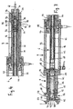
- the retractable assembly shown in Figures 1 to 4 includes a sensor 2, which is removably disposed in the front part 4 of a dip tube 6.
- the dip tube 6 and thus the sensor 2 are axially displaceable relative to a housing 8 between a retracted rest position and an extended working position.
- the dip tube 6 and the sensor 2 are within the housing 8; in the working position shown in Figure 2, the dip tube 6 is extended with the sensor 2 and immersed in a reaction vessel, not shown in detail, to determine measured values in a medium therein.
- a front jacket section 10 of the sensor 2 and an O-ring 12 recessed in the front part 4 of the dip tube 6 form a medium-tight closure of the dip tube 6.
- the dip tube 6 contains a removable tubular insert 16 which can be fixed by means of a closure member 14, by means of which Sensor 2 is advanced in an inserted position against a front stop 18 of the dip tube 6.
- this front stop 18 formed by a step-like constriction in the interior of the dip tube 6, against which the sensor 2 is present with a projection 20 of the sensor shaft 22.
- the closure member 14 is used at the rear end 24 of the dip tube 6 and holds in the inserted position the insert 16 on the sensor 2 and the latter on the front stop 18th
- the retractable assembly is also equipped with a securing device 26, which prevents axial displacement of the dip tube 6 from the rest position when at least one of the components: sensor 2, insert 16 and closure member 14 is missing.
- the housing 8 is composed of a plurality of tubular components, namely a front chamber part 28, a middle chamber part 30, a cylindrical housing part 32 and a rear housing part 34.
- the individual chamber parts are connected by connecting flanges and fastening screws.
- the dip tube 6 has at the front end to a cage 36 which is provided with at least one lateral passage opening 38 in order to ensure the access of measuring medium to the sensor 2 in the extended measuring position.
- the cage 36 has a bottom 40 which forms a front end of the dip tube.
- the cage 36 is welded to a central dip tube part 42, in the inner wall of which said front stop 18 is formed for the sensor 2.
- the middle dip tube part 42 is connected to a piston 44 which is mounted longitudinally displaceably in the cylindrical housing part 32.
- a rear immersion tube part 46 is arranged, which is equipped at the rear end 24 with a receptacle for the closure member 14.
- a plurality of slide bearings 48 are provided between cooperating parts of the housing 8 and the dip tube 6.
- the front chamber part 28 is equipped with a connecting flange 50, by means of which the retractable assembly can be connected to a reaction vessel. Since the front chamber part 28 is designed as a component of the modular housing 8, the retractable fitting can be connected to reaction vessels of different connection mass by using a front chamber part 28 with a correspondingly dimensioned connection flange 50.
- the front chamber part 28 is configured as part of a flushing device for the sensor 2.
- the front chamber part 28 has a rinsing region 56 delimited by a front annular groove 52 and a rear annular groove 54, the peripheral wall 58 of which has at least one inlet 60 and a drain 62 for flushing medium.
- a corresponding sealing ring In each annular groove is a corresponding sealing ring, which forms a medium-tight closure of the flushing area 56 with the outer wall of the dip tube 6.
- the cage 36 In the retracted rest position of the dip tube 6, which also corresponds to a flushing position for the sensor 2, the cage 36 is located within the flushing area 56.
- flushing medium supplied through the inlet 60 can pass through the lateral passage opening 38 of the cage 36 to the sensor 2 located therein.
- An outlet of flushing medium in the retractable fitting is prevented by the arranged between the jacket 10 of the sensor 2 and the inner wall of the dip tube 6 O-ring 12.
- In the extended measuring position is located in the front chamber part 28, an opening-less part of the dip tube 6, so that the flushing portion 56 is limited to the space between the two annular grooves 52 and 54 between the outer wall of the dip tube 6 and the peripheral wall 58.
- the inlet 60 and the outlet 62 is provided with an internally threaded portion in which a corresponding connection part or, as shown in Figures 1 to 3, a sealing plug can be screwed.
- a sealing plug can be screwed.
- the latter is useful, for example, for making tightness tests.
- the sensor 2 has a rear plug-in head with electrical connections, on which a corresponding connection socket 64 with connection cable 66 is plugged.
- the rearwardly step-like tapered connection socket 64 is backed from a correspondingly stepped mouth 68 of the insert 16, wherein the connection cable 66 is guided in the insert 16 to the rear end 24 of the dip tube 6 and there through the closure member 14 to the outside.
- the insert 16 holds the sensor 2 against the front stop 18 of the dip tube 6.
- sensor 2 and insert 16 are not only dimensionally appropriate but also in terms of length so that their combined length approximately corresponds to the immersion tube length.
- the securing device 26 which prevents axial displacement of the dip tube 6 from the rest position when the sensor 2 or the insert 16 or the closure member 14 or a plurality of these components is missing, is constructed as follows.
- the rear immersion tube part 46 contains a securing slide 70, which surrounds the tubular insert 16 at the rear end region 72 in the manner of a sleeve.
- the safety slide 70 is displaceable between a front stop and a rear stop within the rear dip tube part 46 from a first blocking position S1 via a release position F to a second blocking position S2.
- the front stop is formed by a stepped constriction 74 in the interior of the rear dip tube part 46, while the rear stop is formed by a screwed into the wall of the rear immersion tube member 46 or otherwise attached pin 76.
- the outer side wall of the safety slide 70 is designed as a link 78 for a plurality of locking members 80.
- Each locking member 80 consists of a ball which is arranged radially displaceable in an associated through hole in the rear dip tube part 46.
- the safety slide 70 In the first blocking position S1, the safety slide 70 is in contact with the rear stop 76, wherein each locking element 80 rests with its inside on the front stop region 84 of the link 78 and thereby engages with its outside in a locking recess 86 of the housing 8.
- the locking recess 86 is formed as an annular groove on the inner wall of the rear housing part 34. By this engagement, the axial displaceability of the dip tube 6 relative to the housing 8 is locked.
- the safety slide 70 In the second blocking position S2, the safety slide 70 is in contact with the front stop 74, wherein each locking element 80 rests with its inner side on the rear stop area 88 of the link 78 and in turn engages with its outer side in the locking recess 86.
- the safety slide 70 is located in the region between the two stops 74 and 76, so that each locking member 80 engages with the inside in a central circumferential groove 90 of the link 78 and thereby comes free with its outside from the locking recess 86, whereby the axial displacement of the dip tube 6 relative to the housing 8 is released.
- the securing device 26 responds not only to missing, but also to incorrectly installed or incorrectly dimensioned components. This will be explained in more detail below.
- the rear closure member 14 is provided with a laterally projecting pin 98 which engages in an associated L-shaped Einfahrschlitz 100 at the rear end 24 of the dip tube 6.
- a laterally projecting pin 98 engages in an associated L-shaped Einfahrschlitz 100 at the rear end 24 of the dip tube 6.
- the tubular insert 16, the second spring 96 and the closure member 14 are each provided with a continuous lateral recess.
- this recess is accomplished by a per se known non-circumferential arrangement of the spring coils, while it is configured in the insert 16 and the closure member 14 as a continuous lateral slot. Since the connection cable 66 can be inserted into the slotted components without threading from the side, for example Also sensors with bulky plug connections, attached Vorverphasem and the like are used in the retractable housing.
- the retractable assembly is equipped with a rotation lock, which prevents rotation of the dip tube about its longitudinal axis.
- the rear immersion tube part 46 is provided with a projection which engages in an associated longitudinal slot of the rear housing part 34.
- this makes it possible to achieve a defined alignment of the passage openings 38 in the cage 36 with respect to the inlets and outlets of the rinsing area 56.
- the rotation lock ensured with the rotation lock that when using a non-rotationally symmetric sensor whose sensitive surface has a desired orientation, for example with respect to a flow direction in the reaction vessel.
- retractable housing has been shown in horizontal mounting position, it is basically also suitable for a vertical mounting position with downwardly facing sensor part as well as for intermediate mounting positions.
Landscapes
- Health & Medical Sciences (AREA)
- Engineering & Computer Science (AREA)
- Physics & Mathematics (AREA)
- Chemical & Material Sciences (AREA)
- Life Sciences & Earth Sciences (AREA)
- General Physics & Mathematics (AREA)
- Pathology (AREA)
- Molecular Biology (AREA)
- Mechanical Engineering (AREA)
- Chemical Kinetics & Catalysis (AREA)
- Electrochemistry (AREA)
- Analytical Chemistry (AREA)
- Biochemistry (AREA)
- General Health & Medical Sciences (AREA)
- Fluid Mechanics (AREA)
- Immunology (AREA)
- General Engineering & Computer Science (AREA)
- Quick-Acting Or Multi-Walled Pipe Joints (AREA)
- Investigating Or Analyzing Materials By The Use Of Electric Means (AREA)
- Sampling And Sample Adjustment (AREA)
- Examining Or Testing Airtightness (AREA)
- Cable Accessories (AREA)
- Geophysics And Detection Of Objects (AREA)
- Fire Alarms (AREA)
- Measuring Fluid Pressure (AREA)
- Monitoring And Testing Of Nuclear Reactors (AREA)
- Infusion, Injection, And Reservoir Apparatuses (AREA)
- Actuator (AREA)
- Investigating Or Analyzing Materials By The Use Of Magnetic Means (AREA)
Applications Claiming Priority (3)
| Application Number | Priority Date | Filing Date | Title |
|---|---|---|---|
| DE10241833A DE10241833A1 (de) | 2002-09-09 | 2002-09-09 | Wechselarmatur mit einem Sensor |
| DE10241833 | 2002-09-09 | ||
| PCT/EP2003/050604 WO2004023127A1 (de) | 2002-09-09 | 2003-09-01 | Wechselarmatur mit einem sensor |
Publications (2)
| Publication Number | Publication Date |
|---|---|
| EP1540322A1 EP1540322A1 (de) | 2005-06-15 |
| EP1540322B1 true EP1540322B1 (de) | 2006-01-11 |
Family
ID=31724589
Family Applications (1)
| Application Number | Title | Priority Date | Filing Date |
|---|---|---|---|
| EP03793822A Expired - Lifetime EP1540322B1 (de) | 2002-09-09 | 2003-09-01 | Wechselarmatur mit einem sensor |
Country Status (8)
| Country | Link |
|---|---|
| US (1) | US7272983B2 (zh) |
| EP (1) | EP1540322B1 (zh) |
| JP (1) | JP4606164B2 (zh) |
| CN (1) | CN100419415C (zh) |
| AT (1) | ATE315780T1 (zh) |
| AU (1) | AU2003298426A1 (zh) |
| DE (2) | DE10241833A1 (zh) |
| WO (1) | WO2004023127A1 (zh) |
Cited By (2)
| Publication number | Priority date | Publication date | Assignee | Title |
|---|---|---|---|---|
| DE102011079348A1 (de) | 2011-07-18 | 2013-01-24 | Endress + Hauser Conducta Gesellschaft für Mess- und Regeltechnik mbH + Co. KG | Wechselarmatur |
| US20230049638A1 (en) * | 2019-12-30 | 2023-02-16 | Fj Dynamics Technology Co., Ltd | Material pushing apparatus and charging method thereof, and material pushing machine and material pushing method thereof |
Families Citing this family (46)
| Publication number | Priority date | Publication date | Assignee | Title |
|---|---|---|---|---|
| DE102004028789B3 (de) * | 2004-06-16 | 2006-01-05 | Heraeus Electro-Nite International N.V. | Vorrichtung zur Durchführung von Messungen und/oder Probennahmen in Metallschmelzen |
| EP1872042B1 (en) * | 2005-04-22 | 2019-12-18 | Life Technologies Corporation | Tube ports and related container systems |
| DE102005036865B4 (de) * | 2005-08-02 | 2009-02-12 | Knick Elektronische Messgeräte GmbH & Co. KG | Sondeneinrichtung zur Messung von Prozessgrößen, insbesondere physikalisch-chemischer Messgrößen, in Fluiden |
| EP1752763A1 (de) * | 2005-08-10 | 2007-02-14 | Mettler-Toledo AG | Wechselarmatur |
| DE102006010810A1 (de) * | 2006-03-07 | 2007-09-13 | Endress + Hauser Conducta Gesellschaft für Mess- und Regeltechnik mbH + Co. KG | Wechselarmatur |
| DE102006022983A1 (de) * | 2006-05-15 | 2007-11-22 | Knick Elektronische Messgeräte GmbH & Co. KG | Sondeneinrichtung zur Messung von Prozessgrößen, insbesondere physikalisch-chemischer Messgrößen, in Fluiden |
| DE102006022981B4 (de) * | 2006-05-15 | 2017-10-26 | Knick Elektronische Messgeräte GmbH & Co. KG | Sondeneinrichtung zur Messung von Prozessgrößen |
| DE102006022979A1 (de) * | 2006-05-15 | 2007-11-22 | Knick Elektronische Messgeräte GmbH & Co. KG | Sondeneinrichtung zur Messung von Prozessgrößen, insbesondere Schubstangenarmatur |
| DE102006022977B4 (de) * | 2006-05-15 | 2016-09-15 | Knick Elektronische Messgeräte GmbH & Co. KG | Sondeneinrichtung zur Messung von Prozessgrößen, insbesondere Schubstangenarmatur |
| EP1887348B1 (de) * | 2006-06-23 | 2012-12-19 | Mettler-Toledo AG | Tauchrohr für eine Messsonde |
| DE102006048898B4 (de) * | 2006-10-17 | 2010-09-09 | Knick Elektronische Messgeräte GmbH & Co. KG | Sondeneinrichtung zur Messung von Prozessgrößen, insbesondere Schubstangenarmatur |
| DE102006061815A1 (de) | 2006-12-21 | 2008-06-26 | Endress + Hauser Conducta Gesellschaft für Mess- und Regeltechnik mbH + Co. KG | Wechselarmatur |
| US7926412B2 (en) | 2007-12-10 | 2011-04-19 | Endress + Hauser Conducta Gesellschraft für Mess- und Regeltechnik mbH + Co. KG | Retractable assembly for analytical measurements technology |
| DE102007059668A1 (de) * | 2007-12-10 | 2009-06-25 | Endress + Hauser Conducta Gesellschaft für Mess- und Regeltechnik mbH + Co. KG | Tauchwechselarmatur |
| US8562209B2 (en) * | 2009-06-30 | 2013-10-22 | Edan Instruments, Inc. | Method to control the work of electronic thermometer by using the position of probe and the apparatus composed of |
| US8568575B2 (en) * | 2009-09-02 | 2013-10-29 | Invensys Systems, Inc. | Adjustable, retractable probe insertion assembly |
| US20110048971A1 (en) * | 2009-09-02 | 2011-03-03 | Bower Michael M | Robust potentiometric sensor |
| PL2343514T3 (pl) * | 2009-12-22 | 2013-09-30 | Endress Hauser Wetzer Gmbh Co Kg | Armatura montażowa do prętowej sondy |
| DE102010001391A1 (de) * | 2010-01-29 | 2011-08-04 | Endress + Hauser Conducta Gesellschaft für Mess- und Regeltechnik mbH + Co. KG, 70839 | Sondeneinrichtung zum Messen einer Messgröße eines in einem Prozessbehälter enthaltenen Messmediums, insbesondere für sterile Anwendungen |
| DE102010029029A1 (de) | 2010-05-17 | 2011-11-17 | Endress + Hauser Conducta Gesellschaft für Mess- und Regeltechnik mbH + Co. KG | Sondenanordnung |
| US8365617B2 (en) | 2010-06-25 | 2013-02-05 | Mettler-Toledo Ag | Sampling device |
| US8312780B2 (en) | 2010-06-25 | 2012-11-20 | Mettler-Toledo Ag | Sampling device and method |
| US20120103076A1 (en) * | 2010-10-29 | 2012-05-03 | Basf Se | Online-titration in an alternating instrument |
| US8739642B2 (en) * | 2010-11-16 | 2014-06-03 | Chrysler Group Llc | Sensor assembly |
| US9186430B2 (en) * | 2010-12-16 | 2015-11-17 | Symmetry Medical Manufacturing Inc. | Apparatus and method for accessing a biological indicator within a container |
| DE102011012175A1 (de) * | 2011-02-23 | 2012-08-23 | Heraeus Electro-Nite International N.V. | Sensoranordnung zur Messung von Parametern in Schmelzen |
| DE202012002473U1 (de) | 2011-03-30 | 2012-05-18 | SONOTEC Dr. zur Horst-Meyer & Münch oHG | Wechselarmatur zum Eintauchen eines Messkopfes in eine Rohrleitung oder in einen Behälter , die ein unter Druck stehendes Fluid enthalten |
| DE102011017535A1 (de) * | 2011-04-26 | 2012-10-31 | Endress + Hauser Conducta Gesellschaft für Mess- und Regeltechnik mbH + Co. KG | Sondeneinrichtung zum Messen einer Messgröße eines in einem Prozessbehälter enthaltenen Prozessmediums |
| WO2012149449A2 (en) * | 2011-04-29 | 2012-11-01 | Bruker Nano, Inc. | Cleaning station for atomic force microscope |
| DE102011080579A1 (de) | 2011-08-08 | 2013-02-28 | Endress + Hauser Conducta Gesellschaft für Mess- und Regeltechnik mbH + Co. KG | Wechselarmatur |
| JP6199301B2 (ja) * | 2011-10-28 | 2017-09-20 | ジーイー・ヘルスケア・バイオサイエンス・コーポレイション | プローブアセンブリー及び方法 |
| US10859412B2 (en) | 2011-10-28 | 2020-12-08 | Global Life Sciences Solutions Usa Llc | Probe assembly |
| DE102011089842A1 (de) * | 2011-12-23 | 2013-06-27 | Endress + Hauser Flowtec Ag | Wechselarmatur für einen Sensor |
| DE102011089942A1 (de) * | 2011-12-27 | 2013-06-27 | Endress + Hauser Wetzer Gmbh + Co. Kg | Aufnahmevorrichtung für einen Messeinsatz |
| DE102012103874A1 (de) * | 2012-05-03 | 2013-11-07 | Endress + Hauser Conducta Gesellschaft für Mess- und Regeltechnik mbH + Co. KG | Wechselarmatur |
| DE102012104412A1 (de) * | 2012-05-22 | 2013-11-28 | Endress + Hauser Conducta Gesellschaft für Mess- und Regeltechnik mbH + Co. KG | Wechselarmatur |
| KR101277773B1 (ko) * | 2012-12-28 | 2013-06-24 | 우진 일렉트로나이트(주) | 홀더 교체부재 및 이를 포함하는 홀더 조립체 |
| DE102013103459B4 (de) * | 2013-04-08 | 2022-04-14 | Endress+Hauser Conducta Gmbh+Co. Kg | Wechselarmatur für Eintauch-, Durchfluss- und Anbau- Messsysteme |
| DE102013113810B4 (de) * | 2013-12-11 | 2023-02-09 | Endress + Hauser Wetzer Gmbh + Co. Kg | Kupplungssystem für eine Armatur zur Aufnahme eines Messeinsatzes, wobei das Kupplungssystem eine schraubenförmige Nut mit vier Teilbereichen besitzt |
| GB201415636D0 (en) | 2014-08-08 | 2014-10-22 | Ge Healthcare Bio Sciences | Sterile sensor insertion |
| BR102014033086A2 (pt) * | 2014-12-30 | 2016-10-18 | Ecil Met Tec Ltda | sonda de imersão e conjunto de sublança de imersão e sonda de imersão para um forno conversor |
| WO2019129570A1 (en) * | 2017-12-28 | 2019-07-04 | Ge Healthcare Bio-Sciences Corp. | Probe assembly and method for securing and inserting a probe |
| CN108246695B (zh) * | 2018-01-16 | 2024-04-30 | 深圳迎凯生物科技有限公司 | 采样针清洗装置 |
| DE102018105174B4 (de) * | 2018-03-07 | 2020-03-12 | Presens Precision Sensing Gmbh | Analyseeinheit |
| DE102019122096A1 (de) * | 2019-08-16 | 2021-02-18 | Endress+Hauser Conducta Gmbh+Co. Kg | Optochemischer Sensor und Verfahren |
| CN112729374B (zh) * | 2020-12-21 | 2023-03-07 | 安徽国星生物化学有限公司 | 一种2-羟乙基吡啶常压合成的环境反馈智能监测装置 |
Family Cites Families (20)
| Publication number | Priority date | Publication date | Assignee | Title |
|---|---|---|---|---|
| JPS59500655A (ja) * | 1982-04-26 | 1984-04-19 | バイオエンジニアリング・アクチエンゲゼルシヤフト | 可変ゾンデ |
| DE3709019A1 (de) * | 1987-03-19 | 1988-09-29 | Roesler Gleitschlifftech Masch | Verfahren und vorrichtung zur durchfuehrung von messvorgaengen in agressiven medien |
| DE3868935D1 (de) * | 1988-12-02 | 1992-04-09 | Yokogawa Europ Bv | Vorrichtung zum festhalten eines elektrodenhalters. |
| ES2043341T3 (es) * | 1989-03-02 | 1993-12-16 | Ciba Geigy Ag | Dispositivo para la determinacion de valores electroquimicos en solucion acuosa. |
| DE8909902U1 (zh) * | 1989-08-18 | 1989-10-05 | Conducta Gmbh & Co, 7016 Gerlingen, De | |
| DE3940948A1 (de) * | 1989-12-12 | 1991-06-13 | Conducta Mess & Regeltech | Verfahren zur kontinuierlichen elektrolytzufuehrung und referenzelektrodensystem |
| DE4140286C2 (de) * | 1991-12-06 | 1994-01-27 | Conducta Mess & Regeltech | Elektrodenhalterung für Eintauch-, Durchfluß- und Anbau-Meßsystem in der analytischen Chemie |
| DE9202350U1 (zh) * | 1992-02-24 | 1992-04-16 | Leybold Ag, 6450 Hanau, De | |
| US5296197A (en) * | 1992-07-09 | 1994-03-22 | Nl Technologies, Limited | Automated sample extractor or feeder/inoculator for bioreactors and similar equipment |
| EP0590290A1 (de) * | 1992-09-28 | 1994-04-06 | Mettler-Toledo AG | Wechselarmatur mit einem Sensor |
| DE19546266C2 (de) * | 1995-12-12 | 1998-09-24 | Conducta Endress & Hauser | Vorrichtung zur Aufnahme und Halterung einer Meßelektrode |
| DE19720504B4 (de) * | 1997-05-16 | 2005-07-07 | Endress + Hauser Conducta Gesellschaft für Mess- und Regeltechnik mbH + Co. KG | Vorrichtung zur Aufnahme und Halterung einer Messelektrode |
| DE29720248U1 (de) * | 1997-06-04 | 1998-02-12 | Mettler Toledo Gmbh | Wechselarmatur |
| DE19723681C2 (de) * | 1997-06-05 | 2001-05-17 | Exner Ges Fuer Analysenmesstec | Vorrichtung zur Bestimmung von insbesondere elektrochemischen und/oder optischen Eigenschaften von Flüssigkeiten |
| JP3295619B2 (ja) * | 1997-07-16 | 2002-06-24 | エスエムシー株式会社 | 流体圧シリンダにおけるセンサ取付具 |
| DE19843553C2 (de) * | 1998-09-23 | 2001-09-20 | Bayer Ag | Meßvorrichtung zur In-Prozeß-Kontrolle |
| US6773678B2 (en) * | 2000-03-20 | 2004-08-10 | Endress + Hauser Conducta Gesellschaft Fur Mess Und Regeltechnik Mbh + Co. | Mounting system and retractable sensor holder for analytical sensors |
| DE10024564A1 (de) * | 2000-05-19 | 2001-11-22 | Knick Elektronische Mesgeraete | Sondeneinrichtung zur Aufnahme, Positionierung, Kalibrierung und/oder Wartung einer Meßelektrode |
| US6640658B1 (en) * | 2002-06-11 | 2003-11-04 | Signet Scientific Company | Wet-tap sensor assembly and related method |
| US6860162B1 (en) * | 2004-02-06 | 2005-03-01 | Ben E. Jaeger | Liquid sampler and method |
-
2002
- 2002-09-09 DE DE10241833A patent/DE10241833A1/de not_active Withdrawn
-
2003
- 2003-09-01 AT AT03793822T patent/ATE315780T1/de not_active IP Right Cessation
- 2003-09-01 JP JP2004533515A patent/JP4606164B2/ja not_active Expired - Fee Related
- 2003-09-01 EP EP03793822A patent/EP1540322B1/de not_active Expired - Lifetime
- 2003-09-01 AU AU2003298426A patent/AU2003298426A1/en not_active Abandoned
- 2003-09-01 CN CNB038214008A patent/CN100419415C/zh not_active Expired - Fee Related
- 2003-09-01 WO PCT/EP2003/050604 patent/WO2004023127A1/de active IP Right Grant
- 2003-09-01 DE DE50302206T patent/DE50302206D1/de not_active Expired - Lifetime
-
2005
- 2005-03-09 US US11/075,483 patent/US7272983B2/en not_active Expired - Fee Related
Cited By (2)
| Publication number | Priority date | Publication date | Assignee | Title |
|---|---|---|---|---|
| DE102011079348A1 (de) | 2011-07-18 | 2013-01-24 | Endress + Hauser Conducta Gesellschaft für Mess- und Regeltechnik mbH + Co. KG | Wechselarmatur |
| US20230049638A1 (en) * | 2019-12-30 | 2023-02-16 | Fj Dynamics Technology Co., Ltd | Material pushing apparatus and charging method thereof, and material pushing machine and material pushing method thereof |
Also Published As
| Publication number | Publication date |
|---|---|
| DE50302206D1 (de) | 2006-04-06 |
| JP2005538318A (ja) | 2005-12-15 |
| AU2003298426A1 (en) | 2004-03-29 |
| JP4606164B2 (ja) | 2011-01-05 |
| US7272983B2 (en) | 2007-09-25 |
| EP1540322A1 (de) | 2005-06-15 |
| CN1682109A (zh) | 2005-10-12 |
| DE10241833A1 (de) | 2004-03-18 |
| ATE315780T1 (de) | 2006-02-15 |
| US20050229727A1 (en) | 2005-10-20 |
| WO2004023127A1 (de) | 2004-03-18 |
| CN100419415C (zh) | 2008-09-17 |
Similar Documents
| Publication | Publication Date | Title |
|---|---|---|
| EP1540322B1 (de) | Wechselarmatur mit einem sensor | |
| DE112006003344B4 (de) | Anschluss für eine Kopplungsvorrichtung für Fluidtransfer | |
| EP1752763A1 (de) | Wechselarmatur | |
| DE112006003318T5 (de) | Buchse für eine Kopplungseinrichtung für Fluidtransfer | |
| DE2061978A1 (de) | Messwertgebereinrichtung mit herausnehmbarer Messwertgebersonde | |
| DE3502538C2 (de) | Zylinder mit Lecksicherungsanordnung | |
| EP1203949B1 (de) | Wechselarmatur mit einem Sensor | |
| DE10152409B4 (de) | Stopfen für eine Flüssigkeitsrohr-Verbindungsvorrichtung | |
| DE3820405C2 (de) | Messwertgebervorrichtung | |
| DE102004012214B4 (de) | Entlastungsventil | |
| DE2912977A1 (de) | Entlueftungsventil | |
| EP0669566A1 (de) | Wasser-Dampf-Mischvorrichtung | |
| EP3204669B1 (de) | Ablaufstutzen | |
| DE4200452A1 (de) | Wechselarmatur fuer das einfuehren von messsonden in das in einem unter druck stehenden behaelter befindliche medium | |
| DE2601350C2 (de) | Druckminderventil | |
| DE19900472C1 (de) | Ventil zum Entlüften, Befüllen oder Entleeren insbesondere für Heizkörper oder Heizanlagen | |
| DE3608463C2 (zh) | ||
| DE3902349A1 (de) | Vorrichtung zum auswechseln eines eine unter druck stehende rohrleitung absperrenden ventils | |
| EP0677722A2 (de) | Rohrleitungs-Pass-Stück, insbesondere für opto-elektronische Volumenstrom-Messungen in Rohrleitungen | |
| DE102020101262B4 (de) | Kupplungseinrichtung zum Verbinden von hydraulischen Leitungen und Prüfsystem mit einer Kupplungseinrichtung | |
| DE1209381B (de) | Hahn mit auswechselbarer Messblende | |
| DE4310700A1 (de) | Kupplung für eine koaxiale Anordnung von mindestens zwei Rohrleitungen | |
| LU88841A1 (de) | Dauerdruck-Feuerloescher fuer ein Loeschmittel auf Wasserbasis | |
| DE3141565C1 (de) | Füllpistole zum Auffüllen von Hydraulikeinheiten mit Arbeitsflüssigkeit | |
| DE3237350A1 (de) | Vorrichtung zur gas- oder pressluftentnahme |
Legal Events
| Date | Code | Title | Description |
|---|---|---|---|
| PUAI | Public reference made under article 153(3) epc to a published international application that has entered the european phase |
Free format text: ORIGINAL CODE: 0009012 |
|
| 17P | Request for examination filed |
Effective date: 20050411 |
|
| AK | Designated contracting states |
Kind code of ref document: A1 Designated state(s): AT BE BG CH CY CZ DE DK EE ES FI FR GB GR HU IE IT LI LU MC NL PT RO SE SI SK TR |
|
| AX | Request for extension of the european patent |
Extension state: AL LT LV MK |
|
| GRAP | Despatch of communication of intention to grant a patent |
Free format text: ORIGINAL CODE: EPIDOSNIGR1 |
|
| GRAS | Grant fee paid |
Free format text: ORIGINAL CODE: EPIDOSNIGR3 |
|
| GRAA | (expected) grant |
Free format text: ORIGINAL CODE: 0009210 |
|
| DAX | Request for extension of the european patent (deleted) | ||
| AK | Designated contracting states |
Kind code of ref document: B1 Designated state(s): AT BE BG CH CY CZ DE DK EE ES FI FR GB GR HU IE IT LI LU MC NL PT RO SE SI SK TR |
|
| PG25 | Lapsed in a contracting state [announced via postgrant information from national office to epo] |
Ref country code: SI Free format text: LAPSE BECAUSE OF FAILURE TO SUBMIT A TRANSLATION OF THE DESCRIPTION OR TO PAY THE FEE WITHIN THE PRESCRIBED TIME-LIMIT Effective date: 20060111 Ref country code: NL Free format text: LAPSE BECAUSE OF FAILURE TO SUBMIT A TRANSLATION OF THE DESCRIPTION OR TO PAY THE FEE WITHIN THE PRESCRIBED TIME-LIMIT Effective date: 20060111 Ref country code: SK Free format text: LAPSE BECAUSE OF FAILURE TO SUBMIT A TRANSLATION OF THE DESCRIPTION OR TO PAY THE FEE WITHIN THE PRESCRIBED TIME-LIMIT Effective date: 20060111 Ref country code: FI Free format text: LAPSE BECAUSE OF FAILURE TO SUBMIT A TRANSLATION OF THE DESCRIPTION OR TO PAY THE FEE WITHIN THE PRESCRIBED TIME-LIMIT Effective date: 20060111 Ref country code: RO Free format text: LAPSE BECAUSE OF FAILURE TO SUBMIT A TRANSLATION OF THE DESCRIPTION OR TO PAY THE FEE WITHIN THE PRESCRIBED TIME-LIMIT Effective date: 20060111 Ref country code: IE Free format text: LAPSE BECAUSE OF FAILURE TO SUBMIT A TRANSLATION OF THE DESCRIPTION OR TO PAY THE FEE WITHIN THE PRESCRIBED TIME-LIMIT Effective date: 20060111 Ref country code: IT Free format text: LAPSE BECAUSE OF FAILURE TO SUBMIT A TRANSLATION OF THE DESCRIPTION OR TO PAY THE FEE WITHIN THE PRESCRIBED TIME-LIMIT;WARNING: LAPSES OF ITALIAN PATENTS WITH EFFECTIVE DATE BEFORE 2007 MAY HAVE OCCURRED AT ANY TIME BEFORE 2007. THE CORRECT EFFECTIVE DATE MAY BE DIFFERENT FROM THE ONE RECORDED. Effective date: 20060111 |
|
| RTI1 | Title (correction) |
Free format text: RETRACTABLE HOUSING COMPRISING A SENSOR |
|
| REG | Reference to a national code |
Ref country code: CH Ref legal event code: EP |
|
| REG | Reference to a national code |
Ref country code: IE Ref legal event code: FG4D Free format text: LANGUAGE OF EP DOCUMENT: GERMAN |
|
| REF | Corresponds to: |
Ref document number: 50302206 Country of ref document: DE Date of ref document: 20060406 Kind code of ref document: P |
|
| PG25 | Lapsed in a contracting state [announced via postgrant information from national office to epo] |
Ref country code: DK Free format text: LAPSE BECAUSE OF FAILURE TO SUBMIT A TRANSLATION OF THE DESCRIPTION OR TO PAY THE FEE WITHIN THE PRESCRIBED TIME-LIMIT Effective date: 20060411 Ref country code: BG Free format text: LAPSE BECAUSE OF FAILURE TO SUBMIT A TRANSLATION OF THE DESCRIPTION OR TO PAY THE FEE WITHIN THE PRESCRIBED TIME-LIMIT Effective date: 20060411 Ref country code: SE Free format text: LAPSE BECAUSE OF FAILURE TO SUBMIT A TRANSLATION OF THE DESCRIPTION OR TO PAY THE FEE WITHIN THE PRESCRIBED TIME-LIMIT Effective date: 20060411 |
|
| GBT | Gb: translation of ep patent filed (gb section 77(6)(a)/1977) |
Effective date: 20060327 |
|
| PG25 | Lapsed in a contracting state [announced via postgrant information from national office to epo] |
Ref country code: ES Free format text: LAPSE BECAUSE OF FAILURE TO SUBMIT A TRANSLATION OF THE DESCRIPTION OR TO PAY THE FEE WITHIN THE PRESCRIBED TIME-LIMIT Effective date: 20060422 |
|
| PG25 | Lapsed in a contracting state [announced via postgrant information from national office to epo] |
Ref country code: PT Free format text: LAPSE BECAUSE OF FAILURE TO SUBMIT A TRANSLATION OF THE DESCRIPTION OR TO PAY THE FEE WITHIN THE PRESCRIBED TIME-LIMIT Effective date: 20060612 |
|
| NLV1 | Nl: lapsed or annulled due to failure to fulfill the requirements of art. 29p and 29m of the patents act | ||
| REG | Reference to a national code |
Ref country code: CH Ref legal event code: PFA Owner name: METTLER-TOLEDO AG Free format text: METTLER-TOLEDO GMBH#IM LANGACHER#8606 GREIFENSEE (CH) -TRANSFER TO- METTLER-TOLEDO AG#IM LANGACHER#8606 GREIFENSEE (CH) |
|
| REG | Reference to a national code |
Ref country code: IE Ref legal event code: FD4D |
|
| RAP2 | Party data changed (patent owner data changed or rights of a patent transferred) |
Owner name: METTLER-TOLEDO AG |
|
| ET | Fr: translation filed | ||
| PG25 | Lapsed in a contracting state [announced via postgrant information from national office to epo] |
Ref country code: MC Free format text: LAPSE BECAUSE OF NON-PAYMENT OF DUE FEES Effective date: 20060930 Ref country code: BE Free format text: LAPSE BECAUSE OF NON-PAYMENT OF DUE FEES Effective date: 20060930 |
|
| PLBE | No opposition filed within time limit |
Free format text: ORIGINAL CODE: 0009261 |
|
| STAA | Information on the status of an ep patent application or granted ep patent |
Free format text: STATUS: NO OPPOSITION FILED WITHIN TIME LIMIT |
|
| 26N | No opposition filed |
Effective date: 20061012 |
|
| REG | Reference to a national code |
Ref country code: FR Ref legal event code: CJ Ref country code: FR Ref legal event code: CD |
|
| PG25 | Lapsed in a contracting state [announced via postgrant information from national office to epo] |
Ref country code: AT Free format text: LAPSE BECAUSE OF NON-PAYMENT OF DUE FEES Effective date: 20060901 |
|
| BERE | Be: lapsed |
Owner name: METTLER-TOLEDO GMBH Effective date: 20060930 |
|
| PG25 | Lapsed in a contracting state [announced via postgrant information from national office to epo] |
Ref country code: CZ Free format text: LAPSE BECAUSE OF FAILURE TO SUBMIT A TRANSLATION OF THE DESCRIPTION OR TO PAY THE FEE WITHIN THE PRESCRIBED TIME-LIMIT Effective date: 20060111 Ref country code: GR Free format text: LAPSE BECAUSE OF FAILURE TO SUBMIT A TRANSLATION OF THE DESCRIPTION OR TO PAY THE FEE WITHIN THE PRESCRIBED TIME-LIMIT Effective date: 20060412 |
|
| PG25 | Lapsed in a contracting state [announced via postgrant information from national office to epo] |
Ref country code: EE Free format text: LAPSE BECAUSE OF FAILURE TO SUBMIT A TRANSLATION OF THE DESCRIPTION OR TO PAY THE FEE WITHIN THE PRESCRIBED TIME-LIMIT Effective date: 20060111 |
|
| PG25 | Lapsed in a contracting state [announced via postgrant information from national office to epo] |
Ref country code: LU Free format text: LAPSE BECAUSE OF NON-PAYMENT OF DUE FEES Effective date: 20060901 Ref country code: TR Free format text: LAPSE BECAUSE OF FAILURE TO SUBMIT A TRANSLATION OF THE DESCRIPTION OR TO PAY THE FEE WITHIN THE PRESCRIBED TIME-LIMIT Effective date: 20060111 Ref country code: HU Free format text: LAPSE BECAUSE OF FAILURE TO SUBMIT A TRANSLATION OF THE DESCRIPTION OR TO PAY THE FEE WITHIN THE PRESCRIBED TIME-LIMIT Effective date: 20060712 |
|
| PG25 | Lapsed in a contracting state [announced via postgrant information from national office to epo] |
Ref country code: CY Free format text: LAPSE BECAUSE OF FAILURE TO SUBMIT A TRANSLATION OF THE DESCRIPTION OR TO PAY THE FEE WITHIN THE PRESCRIBED TIME-LIMIT Effective date: 20060111 |
|
| REG | Reference to a national code |
Ref country code: CH Ref legal event code: PCOW Free format text: NEW ADDRESS: IM LANGACHER 44, 8606 GREIFENSEE (CH) |
|
| PGFP | Annual fee paid to national office [announced via postgrant information from national office to epo] |
Ref country code: DE Payment date: 20140930 Year of fee payment: 12 |
|
| REG | Reference to a national code |
Ref country code: FR Ref legal event code: PLFP Year of fee payment: 13 |
|
| PGFP | Annual fee paid to national office [announced via postgrant information from national office to epo] |
Ref country code: FR Payment date: 20150624 Year of fee payment: 13 |
|
| PGFP | Annual fee paid to national office [announced via postgrant information from national office to epo] |
Ref country code: GB Payment date: 20150825 Year of fee payment: 13 Ref country code: CH Payment date: 20150724 Year of fee payment: 13 |
|
| REG | Reference to a national code |
Ref country code: CH Ref legal event code: PFA Owner name: METTLER-TOLEDO GMBH, CH Free format text: FORMER OWNER: METTLER-TOLEDO AG, CH |
|
| REG | Reference to a national code |
Ref country code: DE Ref legal event code: R119 Ref document number: 50302206 Country of ref document: DE |
|
| PG25 | Lapsed in a contracting state [announced via postgrant information from national office to epo] |
Ref country code: DE Free format text: LAPSE BECAUSE OF NON-PAYMENT OF DUE FEES Effective date: 20160401 |
|
| REG | Reference to a national code |
Ref country code: CH Ref legal event code: PL |
|
| GBPC | Gb: european patent ceased through non-payment of renewal fee |
Effective date: 20160901 |
|
| REG | Reference to a national code |
Ref country code: FR Ref legal event code: ST Effective date: 20170531 |
|
| PG25 | Lapsed in a contracting state [announced via postgrant information from national office to epo] |
Ref country code: LI Free format text: LAPSE BECAUSE OF NON-PAYMENT OF DUE FEES Effective date: 20160930 Ref country code: GB Free format text: LAPSE BECAUSE OF NON-PAYMENT OF DUE FEES Effective date: 20160901 Ref country code: CH Free format text: LAPSE BECAUSE OF NON-PAYMENT OF DUE FEES Effective date: 20160930 Ref country code: FR Free format text: LAPSE BECAUSE OF NON-PAYMENT OF DUE FEES Effective date: 20160930 |