EP1540069B1 - Hitzebest ndiger b geltischbezug mit elastischer polste rung - Google Patents
Hitzebest ndiger b geltischbezug mit elastischer polste rung Download PDFInfo
- Publication number
- EP1540069B1 EP1540069B1 EP03784030A EP03784030A EP1540069B1 EP 1540069 B1 EP1540069 B1 EP 1540069B1 EP 03784030 A EP03784030 A EP 03784030A EP 03784030 A EP03784030 A EP 03784030A EP 1540069 B1 EP1540069 B1 EP 1540069B1
- Authority
- EP
- European Patent Office
- Prior art keywords
- ironing board
- padding
- ironing
- board
- combination according
- Prior art date
- Legal status (The legal status is an assumption and is not a legal conclusion. Google has not performed a legal analysis and makes no representation as to the accuracy of the status listed.)
- Expired - Lifetime
Links
- 238000010409 ironing Methods 0.000 title claims abstract description 96
- 239000011324 bead Substances 0.000 claims abstract description 12
- 239000004745 nonwoven fabric Substances 0.000 claims abstract 5
- 239000002759 woven fabric Substances 0.000 claims abstract 5
- 239000000463 material Substances 0.000 claims description 8
- 229920000642 polymer Polymers 0.000 claims description 6
- 238000005470 impregnation Methods 0.000 claims description 3
- 238000004132 cross linking Methods 0.000 claims description 2
- 239000004744 fabric Substances 0.000 abstract description 7
- 230000002093 peripheral effect Effects 0.000 description 3
- 238000005452 bending Methods 0.000 description 2
- RYGMFSIKBFXOCR-UHFFFAOYSA-N Copper Chemical compound [Cu] RYGMFSIKBFXOCR-UHFFFAOYSA-N 0.000 description 1
- 229920000742 Cotton Polymers 0.000 description 1
- 229920000914 Metallic fiber Polymers 0.000 description 1
- BQCADISMDOOEFD-UHFFFAOYSA-N Silver Chemical compound [Ag] BQCADISMDOOEFD-UHFFFAOYSA-N 0.000 description 1
- 238000004026 adhesive bonding Methods 0.000 description 1
- AZDRQVAHHNSJOQ-UHFFFAOYSA-N alumane Chemical group [AlH3] AZDRQVAHHNSJOQ-UHFFFAOYSA-N 0.000 description 1
- 230000008094 contradictory effect Effects 0.000 description 1
- 229910052802 copper Inorganic materials 0.000 description 1
- 239000010949 copper Substances 0.000 description 1
- 239000006260 foam Substances 0.000 description 1
- 229910052751 metal Inorganic materials 0.000 description 1
- 239000002184 metal Substances 0.000 description 1
- 230000035699 permeability Effects 0.000 description 1
- 229910052709 silver Inorganic materials 0.000 description 1
- 239000004332 silver Substances 0.000 description 1
- 229920003002 synthetic resin Polymers 0.000 description 1
- 239000000057 synthetic resin Substances 0.000 description 1
- 230000037303 wrinkles Effects 0.000 description 1
Images


Classifications
-
- D—TEXTILES; PAPER
- D06—TREATMENT OF TEXTILES OR THE LIKE; LAUNDERING; FLEXIBLE MATERIALS NOT OTHERWISE PROVIDED FOR
- D06F—LAUNDERING, DRYING, IRONING, PRESSING OR FOLDING TEXTILE ARTICLES
- D06F83/00—Coverings or pads for ironing or pressing members
Definitions
- EP 0 043 700 A1 ironing board covers, in which the cover is directly connected to an elastic padding, for example by gluing, so that the pad cover can not move relative to the elastic padding.
- These laminated covers were then subjected to application of heat and pressure glued to the ironing board itself to make their connection to the ironing board to avoid dislocation of the entire ironing board cover.
- the replacement of such an ironing board cover, in particular its padding from the ironing board for the purpose of replacement is extremely problematic since the padding often very firmly adheres to the ironing board.
- US 4,616,434 shows an ironing board with an ironing board cover with an underlying rubber layer, under which a perforated plate is arranged. By bending over the edges of the sheet, it is fixed on the table top. However, the bending should be done at a distance from the edge of the table, so that a special holder can be inserted at the reference from below between the bent sheet edge and the edge of the table.
- JP60-083700 A an ironing machine has become known in which the two machine parts to be pressed against each other are provided with pads consisting of metallic threads of silver, copper, aluminum parts, cotton and synthetic resin foam. Ironing board covers are not provided. Also, a replaceable attachment of such a support on an ironing board is not considered.
- the invention has the object of providing a heat-resistant ironing board cover with an elastic padding in such a way that it is as easy as possible to connect to the ironing board safely and if necessary can be removed in a simple manner from the ironing board.
- the solution of the problem is achieved in a combination comprising a heat-resistant ironing board cover with elastic padding and an ironing table according to the invention that the ironing board cover using its padding is positively connected to the ironing board, and that the padding on its underside and the ironing board on its top at least partially provided with a fleece or fabric layer, which cover each other after the ironing board cover on the ironing board and are effective as a Velcro connection.
- the ironing board cover is designed so that it can produce a positive connection with the ironing board itself.
- a fleece or fabric layer which is provided with hooks, glued.
- the entire surface of the ironing board can be used. But it is also possible to provide only the edge of the ironing board with the fleece or fabric layer or in addition to attach even strip on the ironing board.
- the padding in turn is provided in the same way with a fleece or fabric layer, which is equipped with eyelets.
- the fleece or fabric layer on the ironing board and on the upholstery must be made congruent. If such a designed upholstery placed on the appropriately trained ironing board, it is possible to connect the ironing board cover alone by pressing it by hand and stroke with the ironing table immovable.
- the fleece or fabric layer of the ironing board or the padding is perforated.
- An equally effective attachment of the heat-resistant ironing board cover with elastic padding on an ironing board can also be achieved in that the contour of the padding corresponds to the contour of the ironing board and that the padding is provided with a peripheral edge, the one behind the peripheral edge of the ironing table bead Has.
- such ironing board cover can be easily clamped by hand on the ironing board. Since it is held all around from all sides, it can not slip on the ironing board.
- the padding in the region of the bead has a material stiffening.
- This material stiffening can be achieved by a special impregnation of the padding in the region of the bead with a polymer and subsequent crosslinking of the polymer.
- the thickness of the padding can be adapted to the performed Velcro operation and is usually 0.2 to 5 cm.
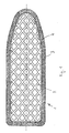
- an ironing board 1 is shown in plan view.
- the ironing board 1 has a table surface 2 made of expanded metal in a conventional manner. Around the entire edge 3 of the table surface 2 around a fleece layer 4 is glued, the top is provided with barbs for a Velcro connection.
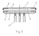
- the padding 5, see Figure 2, the ironing board cover 6 is formed in its contour so that it corresponds to the contour of the ironing board 1.
- it is also provided on its underside 7 with a nonwoven layer 8, which corresponds in shape to the nonwoven layer 8 on the upper side 9 of the ironing board 1.
- this nonwoven layer 4 is provided with eyelets, so that the hooks of the nonwoven layer 4 of the ironing board can get caught in them.
- FIGs 3 and 4 another possibility of the positive connection of the ironing board cover 6 with the ironing board 1 is shown.
- a contour of the padding 5 is provided, which corresponds to the contour of the ironing board 1.
- the connection of the padding 5 with the ironing board 1 is effected in that the padding 5 is provided with a peripheral edge 13, which has a circumferential edge 11 of the ironing board 1 engaging behind bead 12.
- the padding 5 is provided with a material stiffening, which is indicated by the compacted tightening. By this material stiffening the seat of the Ironing cover 6 on the ironing board 1 still reinforced.
- the padding 5 can be soaked in the region of the bead 12 with a crosslinkable polymer. After impregnation, the polymer is cured by, for example, application of heat.
- FIG. 5 an embodiment of the ironing board 1 is shown in cross section, in which the ironing board 6 is provided at its edge 20 circumferentially with push buttons 21.
- the ironing board cover 6 is mounted on the ironing board 1 and buttoned with the snaps 21, the latter engaging in corresponding receptacles 22 on the underside of the ironing board 1.
Landscapes
- Engineering & Computer Science (AREA)
- Textile Engineering (AREA)
- Irons (AREA)
- Laminated Bodies (AREA)
- Vibration Dampers (AREA)
- Golf Clubs (AREA)
- Refuge Islands, Traffic Blockers, Or Guard Fence (AREA)
Description
- Um gute Ergebnisse beim Bügelvorgang zu erreichen, ist es erforderlich, dass die Bügeltischbezüge und die elastische Polsterung während des Bügelns sich nicht verwerfen und Falten bilden, die sich auf den zu bügelnden Gegenstand übertragen können. Häufig werden deshalb die Polsterungen auf den Bügeltisch aufgelegt und der hitzebeständige Bügeltischbezug darüber ausgebreitet und mit Hilfe von Gummibändern oder auch anderen Bändern am Bügeltisch befestigt. Diese Lösung bringt nicht immer das erwünschte Ergebnis.
- Es ist deshalb bekannt geworden, EP 0 043 700 A1, Bügeltischbezüge zu verwenden, bei denen der Bezug mit einer elastischen Polsterung direkt verbunden ist, beispielsweise durch Verkleben, so dass der Bügelbezug sich nicht gegenüber der elastischen Polsterung verschieben kann. Diese laminierten Bezüge wurden sodann unter Anwendung von Hitze und Druck mit dem Bügeltisch selbst verklebt um dadurch ihre Verbindung zum Bügeltisch herzustellen um ein Verrücken des gesamten Bügeltischbezuges zu vermeiden. Die Ablösung eines solchen Bügeltischbezugs, insbesondere seiner Polsterung vom Bügeltisch zwecks Auswechslung ist jedoch äußerst problematisch da die Polsterung häufig sehr fest am Bügeltisch haftet.
- In der Druckschrift GB 2 116 216 A sind deshalb Materialien für die Polsterung vorgeschlagen, welche sich leichter vom Bügeltisch entfemen lassen, so dass eine leichtere Auswechslung des Bügeltischbezugs einschließlich der Polsterung möglich ist. Die sich widersprechenden Bedingungen, nämlich einerseits die sichere Haftung des Bügeltischbezugs und seiner Polsterung am Bügeltisch und andererseits dessen mögliche Auswechselbarkeit führen jedoch nach wie vor zu unbefriedigenden Ergebnissen.
- Die US 4,616,434 zeigt einen Bügeltisch mit einem Bügeltischbezug mit einer darunter liegenden Gummischicht, unter der ein perforiertes Blech angeordnet ist. Durch ein Umbiegen der Ränder des Bleches wird dasselbe auf der Tischoberfläsche befestigt. Das Umbiegen soll jedoch mit Abstand zur Tischkante erfolgen, damit ein besonderer Halter am Bezug von unten her zwischen den umgebogenen Blechrand und die Tischkante eingeschoben werden kann.
- Schließlich ist aus der JP60-083700 A eine Bügelmaschine bekannt geworden, bei der die beiden aufeinander zu pressenden Maschinenteile mit Auflagen versehen sind, die aus metallischen Fäden aus Silber, Kupfer, Aluminiumteilen, Baumwolle und Kunstharzschaum bestehen. Bügeltischbezüge sind nicht vorgesehen. Auch ist ein auswechselbares Anbringen einer solchen Auflage auf einem Bügeltisch nicht in Betracht gezogen.
- Der Erfindung liegt die Aufgabe zugrunde, einen hitzebeständigen Bügeltischbezug mit einer elastischen Polsterung so auszubilden, dass er auf möglichst einfach Weise mit dem Bügeltisch sicher zu verbinden ist und bei Bedarf ebenso in einfacher Weise vom Bügeltisch abgenommen werden kann.
- Die Lösung der gestellten Aufgabe wird bei einer Kombination umfassend einen hitzebeständigen Bügeltischbezug mit elastischer Polsterung und einen Bügeltisch erfindungsgemäß dadurch erreicht, dass der Bügeltischbezug unter Verwendung seiner Polsterung formschlüssig mit dem Bügeltisch verbindbar ist, und dass die Polsterung auf ihrer Unterseite und der Bügeltisch auf seiner Oberseite zumindest teilweise mit einer Vlies- oder Gewebeschicht versehen sind, die nach Auflage des Bügeltischbezugs auf den Bügeltisch einander decken und als Klettverbindung wirksam sind. Der Bügeltischbezug wird so ausgestaltet, dass er eine formschlüssige Verbindung mit dem Bügeltisch selbst herstellen kann.
- Am Bügeltisch wird eine Vlies- oder Gewebeschicht, die mit Haken versehen ist, aufgeklebt. Hierfür kann die gesamte Fläche des Bügeltischs herangezogen werden. Möglich ist aber auch, lediglich den Rand des Bügeltisches mit der Vlies- oder Gewebeschicht zu versehen oder zusätzlich hierzu noch Querstreifen auf dem Bügeltisch anzubringen. Die Polsterung ihrerseits wird in gleicher Weise mit einer Vlies- oder Gewebeschicht versehen, die mit Ösen ausgestattet ist. Die Vlies- oder Gewebeschicht auf dem Bügeltisch und auf der Polsterung sind deckungsgleich auszuführen. Wird eine so ausgestaltete Polsterung auf den entsprechend ausgebildeten Bügeltisch aufgelegt, so ist es möglich, den Bügeltischbezug allein durch Andrücken von Hand und darüber streichen mit dem Bügeltisch unverrückbar zu verbinden.
- Damit die Durchlässigkeit des Bügeltisches für Dampf oder dergleichen nicht behindert wird, ist die Vlies- oder Gewebeschicht des Bügeltisches bzw. der Polsterung perforiert.
- Eine in gleicher Weise wirksame Befestigung des hitzebeständigen Bügeltischbezugs mit elastischer Polsterung auf einem Bügeltisch kann auch dadurch erreicht werden, dass die Kontur der Polsterung der Kontur des Bügeltischs entspricht und dass die Polsterung mit einem Umlaufrand versehen ist, der eine die umlaufende Kante des Bügeltisches hintergreifende Wulst hat. Bei entsprechend angepaßter Ausgestaltung kann ein solcher Bügeltischbezug von Hand sehr einfach auf den Bügeltisch aufgespannt werden. Da er rundherum von allen Seiten gehalten ist kann er auch auf dem Bügeltisch nicht verrutschen.
- Bei der voranstehenden Lösung hat es sich als günstig erwiesen, wenn die Polsterung im Bereich der Wulst eine Materialversteifung hat. Diese Materialversteifung kann durch eine spezielle Imprägnierung der Polsterung im Bereich der Wulst mit einem Polymer und anschließender Vernetzung des Polymers erzielt werden.
- Die Dicke der Polsterung kann an den durchgeführten Klettvorgang angepaßt werden und beträgt in der Regel 0,2 bis 5 cm.
- In der beiliegenden Zeichnung sind zwei Beispiele für die Durchführung der Befestigung des Bügeltischbezugs am Bügeltisch dargestellt.
- Es zeigt:
- Fig. 1
- einen Bügeltisch in der Draufsicht mit einer rundum laufenden Vliesschicht,
- Fig. 2
- schematisch den Bügeltisch mit einem Bügeltischbezug im Querschnitt,
- Fig. 3
- einen Abschnitt eines Bügeltisches mit Bügeltischbezug im Schnitt
- Fig. 4
- einen Bügeltisch mit einem aufgebrachten Bügeltischbezug in der Draufsicht und
- Fig. 5
- ein Querschnitt durch den Bügeltisch mit einem Bezug mit Druckknöpfen.
- In der Figur 1 ist ein Bügeltisch 1 in der Draufsicht gezeigt. Der Bügeltisch 1 hat in an sich bekannter Weise eine Tischfläche 2 aus Streckmetall. Um den ganzen Rand 3 der Tischfläche 2 herum ist eine Vliesschicht 4 aufgeklebt, deren Oberseite mit Widerhaken für eine Klettverbindung versehen ist. Die Polsterung 5, siehe Figur 2, des Bügeltischbezugs 6 wird in ihrer Kontur so ausgebildet, dass sie der Kontur des Bügeltisches 1 entspricht. Außerdem wird sie auf ihre Unterseite 7 ebenfalls mit einer Vliesschicht 8 versehen, welche in ihrer Gestalt der Vliesschicht 8 auf der Oberseite 9 des Bügeltisches 1 entspricht. Diese Vliesschicht 4 ist jedoch mit Ösen ausgestattet, so dass die Haken der Vliesschicht 4 des Bügeltisches in diese sich verhaken können.
- In der Figur 2 sind die einzelnen Teile auseinandergezogen dargestellt, so dass sie sichtbar sind. Nach dem Auflegen des Bügeltischbezugs 6 auf dem Bügeltisch 1 und Andrücken von Hand wird eine ausreichend feste Verbindung zwischen dem Bügeltischbezug 6 und dem Bügeltisch 1 hergestellt. Es sei noch angemerkt, dass unter dem Bügeltisch lediglich die Ständer 10 angedeutet sind, alle anderen Teile sind weggelassen.
- In den Figuren 3 und 4 ist eine andere Möglichkeit der formschlüssigen Verbindung des Bügeltischbezugs 6 mit dem Bügeltisch 1 gezeigt. Auch hier ist eine Kontur der Polsterung 5 vorgesehen, die der Kontur des Bügeltisches 1 entspricht. Die Verbindung der Polsterung 5 mit dem Bügeltisch 1 erfolgt jedoch dadurch, dass die Polsterung 5 mit einem umlaufenden Rand 13 versehen ist, welcher eine die umlaufende Kante 11 des Bügeltisches 1 hintergreifende Wulst 12 hat. Im Bereich der Wulst 12 ist die Polsterung 5 mit einer Materialversteifung versehen, die durch die verdichtete Straffierung angedeutet ist. Durch diese Materialversteifung wird der Sitz des Bügeltsichbezugs 6 auf dem Bügeltisch 1 noch verstärkt. Um die Materialversteifung zu erreichen, kann die Polsterung 5 im Bereich der Wulst 12 mit einem vernetzbaren Polymer getränkt werden. Nach der Tränkung wird das Polymer beispielsweise durch Anwendung von Hitze ausgehärtet.
- In der Fig. 5 ist eine Ausführungsform des Bügeltisches 1 im Querschnitt gezeigt, bei der der Bügeltisch 6 an seinem Rand 20 umlaufend mit Druckknöpfen 21 versehen ist. Der Bügeltischbezug 6 wird auf den Bügeltisch 1 aufgezogen und mit den Druckknöpfen 21 festgeknöpft, wobei letztere in entsprechende Aufnahmen 22 an der Unterseite des Bügeltisches 1 eingreifen.
Claims (8)
- Kombination umfassend einen hitzebeständigen Bügeltischbezug mit elastischer Polsterung und einen Bügeltisch, wobei der Bügeltischbezug unter Verwendung seiner Polsterung formschlüssig mit dem Bügeltisch verbindbar ist, dadurch gekennzeichnet, dass die Polsterung (5) auf ihrer Unterseite (7) und der Bügeltisch (1) auf seiner Oberseite (9) zumindest teilweise mit einer Vlies- oder Gewebeschicht (4) versehen sind, die nach Auflage des Bügeltischbezugs (6) auf den Bügeltisch (1) einander decken und als Klettverbindung wirksam sind.
- Kombination nach Anspruch 1, dadurch gekennzeichnet, dass die Vlies-oder Gewebeschicht (4) der Polsterung (5) mit Ösen und die Vlies- oder Gewebeschicht (4) des Bügeltisches (1) mit Haken versehen sind.
- Kombination nach einem der Ansprüche 1 oder 2, dadurch gekennzeichnet, dass die Vlies- oder Gewebeschicht (4) des Bügeltisches (1) bzw. der Polsterung (5) perforiert ist.
- Kombination nach Anspruch 1, dadurch gekennzeichnet, dass die Kontur der Polsterung (5) der Kontur des Bügeltisches (1) entspricht und dass die Polsterung (5) mit einem umlaufenden Rand (13) versehen ist, der eine die umlaufende Kante (11) des Bügeltisches (1) hintergreifende Wulst (12) hat.
- Kombination nach Anspruch 4, dadurch gekennzeichnet, dass die Wulst (12) Druckknöpfe (21) hat, die in entsprechende Aufnahmen (22) an der Unterseite des Bügeltisches (1) einknöpfbar sind.
- Kombination nach einem der Ansprüche 1 oder 4, dadurch gekennzeichnet, dass die Polsterung (5) im Bereich der Wulst (12) eine Materialversteifung hat.
- Kombination nach Anspruch 6, dadurch gekennzeichnet, dass die Materialversteifung durch eine partielle Imprägnierung der Polsterung (5) im Bereich der Wulst (12) mit einem Polymer und anschließender Vernetzung des Polymers erzielt wird.
- Kombination nach einem der Ansprüche 1 bis 7, dadurch gekennzeichnet, dass die Dicke der Polsterung (5) 0,2 bis 5 cm beträgt.
Applications Claiming Priority (3)
| Application Number | Priority Date | Filing Date | Title |
|---|---|---|---|
| DE10235651A DE10235651B4 (de) | 2002-08-02 | 2002-08-02 | Hitzebeständiger Bügeltischbezug mit elastischer Polsterung |
| DE10235651 | 2002-08-02 | ||
| PCT/EP2003/007905 WO2004015192A2 (de) | 2002-08-02 | 2003-07-19 | Hitzebeständiger bügeltischbezug mit elastischer polsterung |
Publications (2)
| Publication Number | Publication Date |
|---|---|
| EP1540069A2 EP1540069A2 (de) | 2005-06-15 |
| EP1540069B1 true EP1540069B1 (de) | 2006-12-27 |
Family
ID=30469415
Family Applications (1)
| Application Number | Title | Priority Date | Filing Date |
|---|---|---|---|
| EP03784030A Expired - Lifetime EP1540069B1 (de) | 2002-08-02 | 2003-07-19 | Hitzebest ndiger b geltischbezug mit elastischer polste rung |
Country Status (11)
| Country | Link |
|---|---|
| US (1) | US20060143954A1 (de) |
| EP (1) | EP1540069B1 (de) |
| CN (1) | CN1678790B (de) |
| AT (1) | ATE349563T1 (de) |
| AU (1) | AU2003258530A1 (de) |
| CA (1) | CA2494522C (de) |
| DE (2) | DE10235651B4 (de) |
| ES (1) | ES2276140T3 (de) |
| PT (1) | PT1540069E (de) |
| UA (1) | UA77844C2 (de) |
| WO (1) | WO2004015192A2 (de) |
Families Citing this family (5)
| Publication number | Priority date | Publication date | Assignee | Title |
|---|---|---|---|---|
| DE102004016056B4 (de) * | 2004-04-01 | 2007-12-06 | Carl Freudenberg Kg | Bügeltischbespannung aus einer Decklage und einer Polsterung |
| DE102006041269A1 (de) * | 2006-09-02 | 2008-03-20 | sellagym-Gymnastik am Arbeitsplatz GbR (vertretungsberechtigter Gesellschafter: Christian Schmid, 81825 München) | Vorrichtung und Verfahren zur therapeutischen und traningstechnischen Planerstellung, Betätigung, Dokumentation und Überwachung |
| US7299573B1 (en) | 2007-03-23 | 2007-11-27 | Karen Kuncken | Reversible, magnetic ironing pad assembly |
| US8794826B2 (en) * | 2011-01-31 | 2014-08-05 | Judith Tracy | Secure, protective cover for use with hot appliances |
| JP6496595B2 (ja) * | 2015-04-08 | 2019-04-03 | 株式会社三幸社 | ズボン仕上げ機の鏝用カバー |
Family Cites Families (30)
| Publication number | Priority date | Publication date | Assignee | Title |
|---|---|---|---|---|
| DE7243030U (de) * | 1973-02-15 | Rehau Plastiks Gmbh | Bügelwalze | |
| US1606053A (en) * | 1926-11-09 | Fastening device eob ijoning-board covers | ||
| US1891179A (en) * | 1928-09-22 | 1932-12-13 | Pruden Leigh | Metal fire resisting ironing board |
| US1881977A (en) * | 1931-09-10 | 1932-10-11 | Sundby Nellie Nelson | Ironing board cover |
| US1870934A (en) * | 1931-11-20 | 1932-08-09 | Us Hoffman Machinery Corp | Pad for garment pressing machines |
| US2026961A (en) * | 1934-06-07 | 1936-01-07 | Mercedes K Brodt | Pad and cover |
| US2031595A (en) * | 1934-11-21 | 1936-02-25 | Hulda E Finck | Ironing board cover |
| US2554111A (en) * | 1945-07-16 | 1951-05-22 | Charles A Leonard | Magnetic electric iron |
| US2874471A (en) * | 1954-09-16 | 1959-02-24 | Arvin Ind Inc | Non-skid ironing table top and pad assembly |
| US2820721A (en) * | 1955-04-28 | 1958-01-21 | Us Rubber Co | Cover cloth |
| GB849720A (en) * | 1959-02-10 | 1960-09-28 | George Levy London Ltd | Improvements relating to garment pressing machines |
| US3324584A (en) * | 1962-10-29 | 1967-06-13 | Pall Corp | Ironing board cover |
| US3430370A (en) * | 1964-10-02 | 1969-03-04 | Doris H Topliffe | Steam ironing board |
| GB1173132A (en) * | 1966-03-18 | 1969-12-03 | Airflow Housewares Ltd | Improvements relating to Ironing Tables |
| DE7013303U (de) * | 1970-04-11 | 1970-08-20 | Fleischer Gottfried | Buegelbelag. |
| US3653135A (en) * | 1970-05-18 | 1972-04-04 | Helen S Jones | Set-in sleeve former |
| GB2079325B (en) * | 1980-07-03 | 1983-11-09 | Celebrity Housewares Ltd | Ironing boards |
| US4360984A (en) * | 1981-07-27 | 1982-11-30 | Ruttenberg Reid W | Portable ironing pad |
| GB2116216B (en) * | 1982-03-09 | 1985-05-09 | Countrystyle Household Product | Ironing board cover |
| JPS6083700A (ja) * | 1983-10-13 | 1985-05-11 | 田中 俊英 | 衣類プレス仕上機の鏝パツド |
| DE3433170A1 (de) * | 1984-09-10 | 1986-03-13 | Dipl.-Ing. Riba Gmbh & Co Kg, 5450 Neuwied | Buegeltisch mit einer halterung fuer ein darueber zu spannendes buegeltuch |
| DE3727166A1 (de) * | 1987-08-14 | 1989-02-23 | Flachglas Ag | Transport- und/oder bearbeitungstisch mit auflage fuer plattenfoermige gegenstaende |
| US4813166A (en) * | 1987-10-06 | 1989-03-21 | Drake Philip A | Ironing board cover |
| US4956928A (en) * | 1989-01-11 | 1990-09-18 | David Lehrman | Apparatus for securing an iron to an ironing board cover |
| JPH04355000A (ja) | 1991-06-03 | 1992-12-09 | Matsushita Electric Ind Co Ltd | アイロン台 |
| US5231777A (en) * | 1992-01-10 | 1993-08-03 | Herbert Glatt | Ironing board cover with tensioned front pocket and periphery |
| DE9208437U1 (de) * | 1992-06-24 | 1992-09-24 | Curt Würstl Vermögensverwaltungs GmbH & Co. KG, 8670 Hof | Schnappverbinder zum Befestigen eines Polsterteils an einem Sitz |
| CA2114783A1 (en) * | 1993-02-17 | 1994-08-18 | Katherine Lalear | Ptfe ironing board cover for applique |
| US5691027A (en) * | 1993-07-27 | 1997-11-25 | Minnesota Mining And Manufacturing Company | Fastener with a dual purpose cover sheet |
| TW427365U (en) * | 1999-03-08 | 2001-03-21 | Hau Wu | Multi-functional foldable ironing table |
-
2002
- 2002-08-02 DE DE10235651A patent/DE10235651B4/de not_active Expired - Fee Related
-
2003
- 2003-07-19 WO PCT/EP2003/007905 patent/WO2004015192A2/de not_active Ceased
- 2003-07-19 PT PT03784030T patent/PT1540069E/pt unknown
- 2003-07-19 US US10/523,560 patent/US20060143954A1/en not_active Abandoned
- 2003-07-19 ES ES03784030T patent/ES2276140T3/es not_active Expired - Lifetime
- 2003-07-19 UA UAA200501920A patent/UA77844C2/uk unknown
- 2003-07-19 EP EP03784030A patent/EP1540069B1/de not_active Expired - Lifetime
- 2003-07-19 AT AT03784030T patent/ATE349563T1/de not_active IP Right Cessation
- 2003-07-19 DE DE50306130T patent/DE50306130D1/de not_active Expired - Fee Related
- 2003-07-19 CA CA002494522A patent/CA2494522C/en not_active Expired - Fee Related
- 2003-07-19 CN CN038208032A patent/CN1678790B/zh not_active Expired - Fee Related
- 2003-07-19 AU AU2003258530A patent/AU2003258530A1/en not_active Abandoned
Also Published As
| Publication number | Publication date |
|---|---|
| CA2494522C (en) | 2009-09-29 |
| UA77844C2 (en) | 2007-01-15 |
| DE10235651B4 (de) | 2007-09-06 |
| CN1678790B (zh) | 2010-06-09 |
| ES2276140T3 (es) | 2007-06-16 |
| US20060143954A1 (en) | 2006-07-06 |
| CN1678790A (zh) | 2005-10-05 |
| DE50306130D1 (de) | 2007-02-08 |
| DE10235651A1 (de) | 2004-02-19 |
| AU2003258530A1 (en) | 2004-02-25 |
| EP1540069A2 (de) | 2005-06-15 |
| CA2494522A1 (en) | 2004-02-19 |
| WO2004015192A3 (de) | 2004-10-14 |
| PT1540069E (pt) | 2007-02-28 |
| WO2004015192A2 (de) | 2004-02-19 |
| ATE349563T1 (de) | 2007-01-15 |
Similar Documents
| Publication | Publication Date | Title |
|---|---|---|
| DE602004009177T2 (de) | Verfahren und Maschine zur Wasserdichtung von halbfertigen Schuhen, Bekleidungsstücken und Zubehörteilen, und durch solches Verfahren oder Maschine halbfertig hergestellte Produkte | |
| DE2732824A1 (de) | Einlage fuer fussbekleidung | |
| DE102010034878A1 (de) | Lenkradheizung-Trägermaterial mit unterschiedlichen Stauchhärten | |
| EP1540069B1 (de) | Hitzebest ndiger b geltischbezug mit elastischer polste rung | |
| DE3819362C3 (de) | Wasserdichter, wasserdampfdurchlässiger Einsatz für Bekleidungsstücke | |
| DE1577602A1 (de) | Polierscheibe und Verfahren zu deren Herstellung | |
| DE3118343C2 (de) | Verbundstoff | |
| EP1647474B1 (de) | Zweiradsattel | |
| DE102009012956A1 (de) | Verfahren zum Herstellen eines Fahrzeugsitzes | |
| DE29712091U1 (de) | Kaschiermaterial für Sitze oder Innenverkleidungen von Fahrzeugen | |
| DE10235655B4 (de) | Bügeltisch | |
| DE102008020850A1 (de) | Bügeleisenschuh | |
| DE1610639C2 (de) | Verfahren zur Herstellung von Kragen, Manschetten o.dgl. | |
| DE102004016056B4 (de) | Bügeltischbespannung aus einer Decklage und einer Polsterung | |
| DE1504385A1 (de) | Verfahren zur Herstellung einer Faserschichtung | |
| DE4010872C2 (de) | ||
| DE202022102472U1 (de) | Satteldeckenunterlage | |
| AT207104B (de) | Armierte Platte bzw. Bahn aus synthetischem Schaumstoff und Verfahren zur Herstellung derselben | |
| DE2250264C3 (de) | Annähknopf mit metallenem Schauflächenbildner | |
| DE1974028U (de) | Plattenfoermige buegelzwischenlage. | |
| EP2760660A1 (de) | Verfahren zum herstellen eines innenausstattungsteils eines fahrzeugs | |
| DE3100385A1 (de) | Schichtstoffkoerper und verfahren zu dessen herstellung | |
| DE1835756U (de) | Tischauflage in form einer schreibunterlage od. dgl. | |
| DE1940509U (de) | Verklebungspresse zum verkleben von textilen flaechengebilden. | |
| DE2915230A1 (de) | Polsterauflage |
Legal Events
| Date | Code | Title | Description |
|---|---|---|---|
| PUAI | Public reference made under article 153(3) epc to a published international application that has entered the european phase |
Free format text: ORIGINAL CODE: 0009012 |
|
| 17P | Request for examination filed |
Effective date: 20050224 |
|
| AK | Designated contracting states |
Kind code of ref document: A2 Designated state(s): AT BE BG CH CY CZ DE DK EE ES FI FR GB GR HU IE IT LI LU MC NL PT RO SE SI SK TR |
|
| AX | Request for extension of the european patent |
Extension state: AL LT LV MK |
|
| DAX | Request for extension of the european patent (deleted) | ||
| GRAP | Despatch of communication of intention to grant a patent |
Free format text: ORIGINAL CODE: EPIDOSNIGR1 |
|
| GRAS | Grant fee paid |
Free format text: ORIGINAL CODE: EPIDOSNIGR3 |
|
| GRAA | (expected) grant |
Free format text: ORIGINAL CODE: 0009210 |
|
| AK | Designated contracting states |
Kind code of ref document: B1 Designated state(s): AT BE BG CH CY CZ DE DK EE ES FI FR GB GR HU IE IT LI LU MC NL PT RO SE SI SK TR |
|
| PG25 | Lapsed in a contracting state [announced via postgrant information from national office to epo] |
Ref country code: SI Free format text: LAPSE BECAUSE OF FAILURE TO SUBMIT A TRANSLATION OF THE DESCRIPTION OR TO PAY THE FEE WITHIN THE PRESCRIBED TIME-LIMIT Effective date: 20061227 Ref country code: DK Free format text: LAPSE BECAUSE OF FAILURE TO SUBMIT A TRANSLATION OF THE DESCRIPTION OR TO PAY THE FEE WITHIN THE PRESCRIBED TIME-LIMIT Effective date: 20061227 Ref country code: CZ Free format text: LAPSE BECAUSE OF FAILURE TO SUBMIT A TRANSLATION OF THE DESCRIPTION OR TO PAY THE FEE WITHIN THE PRESCRIBED TIME-LIMIT Effective date: 20061227 Ref country code: SK Free format text: LAPSE BECAUSE OF FAILURE TO SUBMIT A TRANSLATION OF THE DESCRIPTION OR TO PAY THE FEE WITHIN THE PRESCRIBED TIME-LIMIT Effective date: 20061227 Ref country code: IE Free format text: LAPSE BECAUSE OF FAILURE TO SUBMIT A TRANSLATION OF THE DESCRIPTION OR TO PAY THE FEE WITHIN THE PRESCRIBED TIME-LIMIT Effective date: 20061227 Ref country code: FI Free format text: LAPSE BECAUSE OF FAILURE TO SUBMIT A TRANSLATION OF THE DESCRIPTION OR TO PAY THE FEE WITHIN THE PRESCRIBED TIME-LIMIT Effective date: 20061227 Ref country code: NL Free format text: LAPSE BECAUSE OF FAILURE TO SUBMIT A TRANSLATION OF THE DESCRIPTION OR TO PAY THE FEE WITHIN THE PRESCRIBED TIME-LIMIT Effective date: 20061227 Ref country code: RO Free format text: LAPSE BECAUSE OF FAILURE TO SUBMIT A TRANSLATION OF THE DESCRIPTION OR TO PAY THE FEE WITHIN THE PRESCRIBED TIME-LIMIT Effective date: 20061227 |
|
| REG | Reference to a national code |
Ref country code: GB Ref legal event code: FG4D Free format text: NOT ENGLISH |
|
| GBT | Gb: translation of ep patent filed (gb section 77(6)(a)/1977) |
Effective date: 20070108 |
|
| REG | Reference to a national code |
Ref country code: IE Ref legal event code: FG4D Free format text: LANGUAGE OF EP DOCUMENT: GERMAN |
|
| REF | Corresponds to: |
Ref document number: 50306130 Country of ref document: DE Date of ref document: 20070208 Kind code of ref document: P |
|
| REG | Reference to a national code |
Ref country code: PT Ref legal event code: SC4A Free format text: AVAILABILITY OF NATIONAL TRANSLATION Effective date: 20070129 |
|
| PG25 | Lapsed in a contracting state [announced via postgrant information from national office to epo] |
Ref country code: BG Free format text: LAPSE BECAUSE OF FAILURE TO SUBMIT A TRANSLATION OF THE DESCRIPTION OR TO PAY THE FEE WITHIN THE PRESCRIBED TIME-LIMIT Effective date: 20070327 Ref country code: SE Free format text: LAPSE BECAUSE OF FAILURE TO SUBMIT A TRANSLATION OF THE DESCRIPTION OR TO PAY THE FEE WITHIN THE PRESCRIBED TIME-LIMIT Effective date: 20070327 |
|
| NLV1 | Nl: lapsed or annulled due to failure to fulfill the requirements of art. 29p and 29m of the patents act | ||
| REG | Reference to a national code |
Ref country code: ES Ref legal event code: FG2A Ref document number: 2276140 Country of ref document: ES Kind code of ref document: T3 |
|
| EN | Fr: translation not filed | ||
| PLBE | No opposition filed within time limit |
Free format text: ORIGINAL CODE: 0009261 |
|
| STAA | Information on the status of an ep patent application or granted ep patent |
Free format text: STATUS: NO OPPOSITION FILED WITHIN TIME LIMIT |
|
| 26N | No opposition filed |
Effective date: 20070928 |
|
| BERE | Be: lapsed |
Owner name: CARL FREUDENBERG K.G. Effective date: 20070731 |
|
| REG | Reference to a national code |
Ref country code: CH Ref legal event code: PL |
|
| PG25 | Lapsed in a contracting state [announced via postgrant information from national office to epo] |
Ref country code: MC Free format text: LAPSE BECAUSE OF NON-PAYMENT OF DUE FEES Effective date: 20070731 Ref country code: GR Free format text: LAPSE BECAUSE OF FAILURE TO SUBMIT A TRANSLATION OF THE DESCRIPTION OR TO PAY THE FEE WITHIN THE PRESCRIBED TIME-LIMIT Effective date: 20070328 Ref country code: LI Free format text: LAPSE BECAUSE OF NON-PAYMENT OF DUE FEES Effective date: 20070731 Ref country code: CH Free format text: LAPSE BECAUSE OF NON-PAYMENT OF DUE FEES Effective date: 20070731 Ref country code: FR Free format text: LAPSE BECAUSE OF FAILURE TO SUBMIT A TRANSLATION OF THE DESCRIPTION OR TO PAY THE FEE WITHIN THE PRESCRIBED TIME-LIMIT Effective date: 20070817 |
|
| PG25 | Lapsed in a contracting state [announced via postgrant information from national office to epo] |
Ref country code: BE Free format text: LAPSE BECAUSE OF NON-PAYMENT OF DUE FEES Effective date: 20070731 |
|
| PG25 | Lapsed in a contracting state [announced via postgrant information from national office to epo] |
Ref country code: FR Free format text: LAPSE BECAUSE OF FAILURE TO SUBMIT A TRANSLATION OF THE DESCRIPTION OR TO PAY THE FEE WITHIN THE PRESCRIBED TIME-LIMIT Effective date: 20061227 Ref country code: AT Free format text: LAPSE BECAUSE OF NON-PAYMENT OF DUE FEES Effective date: 20070719 |
|
| PG25 | Lapsed in a contracting state [announced via postgrant information from national office to epo] |
Ref country code: EE Free format text: LAPSE BECAUSE OF FAILURE TO SUBMIT A TRANSLATION OF THE DESCRIPTION OR TO PAY THE FEE WITHIN THE PRESCRIBED TIME-LIMIT Effective date: 20061227 |
|
| PG25 | Lapsed in a contracting state [announced via postgrant information from national office to epo] |
Ref country code: CY Free format text: LAPSE BECAUSE OF FAILURE TO SUBMIT A TRANSLATION OF THE DESCRIPTION OR TO PAY THE FEE WITHIN THE PRESCRIBED TIME-LIMIT Effective date: 20061227 Ref country code: LU Free format text: LAPSE BECAUSE OF NON-PAYMENT OF DUE FEES Effective date: 20070719 |
|
| PGFP | Annual fee paid to national office [announced via postgrant information from national office to epo] |
Ref country code: PT Payment date: 20090612 Year of fee payment: 7 |
|
| PG25 | Lapsed in a contracting state [announced via postgrant information from national office to epo] |
Ref country code: TR Free format text: LAPSE BECAUSE OF FAILURE TO SUBMIT A TRANSLATION OF THE DESCRIPTION OR TO PAY THE FEE WITHIN THE PRESCRIBED TIME-LIMIT Effective date: 20061227 Ref country code: HU Free format text: LAPSE BECAUSE OF FAILURE TO SUBMIT A TRANSLATION OF THE DESCRIPTION OR TO PAY THE FEE WITHIN THE PRESCRIBED TIME-LIMIT Effective date: 20070628 |
|
| PGFP | Annual fee paid to national office [announced via postgrant information from national office to epo] |
Ref country code: ES Payment date: 20090707 Year of fee payment: 7 |
|
| PGFP | Annual fee paid to national office [announced via postgrant information from national office to epo] |
Ref country code: DE Payment date: 20090731 Year of fee payment: 7 Ref country code: GB Payment date: 20090722 Year of fee payment: 7 |
|
| PGFP | Annual fee paid to national office [announced via postgrant information from national office to epo] |
Ref country code: IT Payment date: 20090723 Year of fee payment: 7 |
|
| REG | Reference to a national code |
Ref country code: PT Ref legal event code: MM4A Free format text: LAPSE DUE TO NON-PAYMENT OF FEES Effective date: 20110119 |
|
| GBPC | Gb: european patent ceased through non-payment of renewal fee |
Effective date: 20100719 |
|
| PG25 | Lapsed in a contracting state [announced via postgrant information from national office to epo] |
Ref country code: DE Free format text: LAPSE BECAUSE OF NON-PAYMENT OF DUE FEES Effective date: 20110201 |
|
| REG | Reference to a national code |
Ref country code: DE Ref legal event code: R119 Ref document number: 50306130 Country of ref document: DE Effective date: 20110201 |
|
| PG25 | Lapsed in a contracting state [announced via postgrant information from national office to epo] |
Ref country code: IT Free format text: LAPSE BECAUSE OF NON-PAYMENT OF DUE FEES Effective date: 20100719 Ref country code: PT Free format text: LAPSE BECAUSE OF NON-PAYMENT OF DUE FEES Effective date: 20110119 |
|
| PG25 | Lapsed in a contracting state [announced via postgrant information from national office to epo] |
Ref country code: GB Free format text: LAPSE BECAUSE OF NON-PAYMENT OF DUE FEES Effective date: 20100719 |
|
| REG | Reference to a national code |
Ref country code: ES Ref legal event code: FD2A Effective date: 20110818 |
|
| PG25 | Lapsed in a contracting state [announced via postgrant information from national office to epo] |
Ref country code: ES Free format text: LAPSE BECAUSE OF NON-PAYMENT OF DUE FEES Effective date: 20100720 |