EP1535792B1 - Kraftfahrzeugsitz - Google Patents
Kraftfahrzeugsitz Download PDFInfo
- Publication number
- EP1535792B1 EP1535792B1 EP04106049A EP04106049A EP1535792B1 EP 1535792 B1 EP1535792 B1 EP 1535792B1 EP 04106049 A EP04106049 A EP 04106049A EP 04106049 A EP04106049 A EP 04106049A EP 1535792 B1 EP1535792 B1 EP 1535792B1
- Authority
- EP
- European Patent Office
- Prior art keywords
- lever
- backrest
- seat part
- motor vehicle
- locking
- Prior art date
- Legal status (The legal status is an assumption and is not a legal conclusion. Google has not performed a legal analysis and makes no representation as to the accuracy of the status listed.)
- Expired - Lifetime
Links
- 230000008878 coupling Effects 0.000 claims description 61
- 238000010168 coupling process Methods 0.000 claims description 61
- 238000005859 coupling reaction Methods 0.000 claims description 61
- 230000007246 mechanism Effects 0.000 claims description 49
- 210000000078 claw Anatomy 0.000 claims description 4
- 238000006073 displacement reaction Methods 0.000 claims description 2
- 241001274197 Scatophagus argus Species 0.000 claims 4
- 238000011144 upstream manufacturing Methods 0.000 description 6
- 238000004873 anchoring Methods 0.000 description 4
- 238000004519 manufacturing process Methods 0.000 description 4
- 238000003860 storage Methods 0.000 description 4
- 230000036316 preload Effects 0.000 description 3
- 230000001154 acute effect Effects 0.000 description 2
- 238000010276 construction Methods 0.000 description 2
- 230000000994 depressogenic effect Effects 0.000 description 2
- 238000000034 method Methods 0.000 description 2
- 230000006835 compression Effects 0.000 description 1
- 238000007906 compression Methods 0.000 description 1
- 230000001419 dependent effect Effects 0.000 description 1
- 230000000881 depressing effect Effects 0.000 description 1
- 230000002452 interceptive effect Effects 0.000 description 1
- 238000003825 pressing Methods 0.000 description 1
Images


Classifications
-
- B—PERFORMING OPERATIONS; TRANSPORTING
- B60—VEHICLES IN GENERAL
- B60N—SEATS SPECIALLY ADAPTED FOR VEHICLES; VEHICLE PASSENGER ACCOMMODATION NOT OTHERWISE PROVIDED FOR
- B60N2/00—Seats specially adapted for vehicles; Arrangement or mounting of seats in vehicles
- B60N2/02—Seats specially adapted for vehicles; Arrangement or mounting of seats in vehicles the seat or part thereof being movable, e.g. adjustable
- B60N2/22—Seats specially adapted for vehicles; Arrangement or mounting of seats in vehicles the seat or part thereof being movable, e.g. adjustable the back-rest being adjustable
- B60N2/2245—Seats specially adapted for vehicles; Arrangement or mounting of seats in vehicles the seat or part thereof being movable, e.g. adjustable the back-rest being adjustable provided with a lock mechanism on the upper part of the back-rest
-
- B—PERFORMING OPERATIONS; TRANSPORTING
- B60—VEHICLES IN GENERAL
- B60N—SEATS SPECIALLY ADAPTED FOR VEHICLES; VEHICLE PASSENGER ACCOMMODATION NOT OTHERWISE PROVIDED FOR
- B60N2/00—Seats specially adapted for vehicles; Arrangement or mounting of seats in vehicles
- B60N2/24—Seats specially adapted for vehicles; Arrangement or mounting of seats in vehicles for particular purposes or particular vehicles
- B60N2/30—Non-dismountable or dismountable seats storable in a non-use position, e.g. foldable spare seats
- B60N2/3002—Non-dismountable or dismountable seats storable in a non-use position, e.g. foldable spare seats back-rest movements
- B60N2/3004—Non-dismountable or dismountable seats storable in a non-use position, e.g. foldable spare seats back-rest movements by rotation only
- B60N2/3009—Non-dismountable or dismountable seats storable in a non-use position, e.g. foldable spare seats back-rest movements by rotation only about transversal axis
- B60N2/3013—Non-dismountable or dismountable seats storable in a non-use position, e.g. foldable spare seats back-rest movements by rotation only about transversal axis the back-rest being hinged on the vehicle frame
-
- B—PERFORMING OPERATIONS; TRANSPORTING
- B60—VEHICLES IN GENERAL
- B60N—SEATS SPECIALLY ADAPTED FOR VEHICLES; VEHICLE PASSENGER ACCOMMODATION NOT OTHERWISE PROVIDED FOR
- B60N2/00—Seats specially adapted for vehicles; Arrangement or mounting of seats in vehicles
- B60N2/24—Seats specially adapted for vehicles; Arrangement or mounting of seats in vehicles for particular purposes or particular vehicles
- B60N2/30—Non-dismountable or dismountable seats storable in a non-use position, e.g. foldable spare seats
- B60N2/3038—Cushion movements
- B60N2/3063—Cushion movements by composed movement
- B60N2/3065—Cushion movements by composed movement in a longitudinal-vertical plane
-
- B—PERFORMING OPERATIONS; TRANSPORTING
- B60—VEHICLES IN GENERAL
- B60N—SEATS SPECIALLY ADAPTED FOR VEHICLES; VEHICLE PASSENGER ACCOMMODATION NOT OTHERWISE PROVIDED FOR
- B60N2/00—Seats specially adapted for vehicles; Arrangement or mounting of seats in vehicles
- B60N2/24—Seats specially adapted for vehicles; Arrangement or mounting of seats in vehicles for particular purposes or particular vehicles
- B60N2/30—Non-dismountable or dismountable seats storable in a non-use position, e.g. foldable spare seats
- B60N2/3072—Non-dismountable or dismountable seats storable in a non-use position, e.g. foldable spare seats on a lower level of a multi-level vehicle floor
-
- B—PERFORMING OPERATIONS; TRANSPORTING
- B60—VEHICLES IN GENERAL
- B60N—SEATS SPECIALLY ADAPTED FOR VEHICLES; VEHICLE PASSENGER ACCOMMODATION NOT OTHERWISE PROVIDED FOR
- B60N2/00—Seats specially adapted for vehicles; Arrangement or mounting of seats in vehicles
- B60N2/24—Seats specially adapted for vehicles; Arrangement or mounting of seats in vehicles for particular purposes or particular vehicles
- B60N2/30—Non-dismountable or dismountable seats storable in a non-use position, e.g. foldable spare seats
- B60N2/3088—Non-dismountable or dismountable seats storable in a non-use position, e.g. foldable spare seats characterised by the mechanical link
- B60N2/309—Non-dismountable or dismountable seats storable in a non-use position, e.g. foldable spare seats characterised by the mechanical link rods
-
- B—PERFORMING OPERATIONS; TRANSPORTING
- B60—VEHICLES IN GENERAL
- B60N—SEATS SPECIALLY ADAPTED FOR VEHICLES; VEHICLE PASSENGER ACCOMMODATION NOT OTHERWISE PROVIDED FOR
- B60N2/00—Seats specially adapted for vehicles; Arrangement or mounting of seats in vehicles
- B60N2/24—Seats specially adapted for vehicles; Arrangement or mounting of seats in vehicles for particular purposes or particular vehicles
- B60N2/30—Non-dismountable or dismountable seats storable in a non-use position, e.g. foldable spare seats
- B60N2/3088—Non-dismountable or dismountable seats storable in a non-use position, e.g. foldable spare seats characterised by the mechanical link
- B60N2/3093—Non-dismountable or dismountable seats storable in a non-use position, e.g. foldable spare seats characterised by the mechanical link slides
-
- B—PERFORMING OPERATIONS; TRANSPORTING
- B60—VEHICLES IN GENERAL
- B60N—SEATS SPECIALLY ADAPTED FOR VEHICLES; VEHICLE PASSENGER ACCOMMODATION NOT OTHERWISE PROVIDED FOR
- B60N2/00—Seats specially adapted for vehicles; Arrangement or mounting of seats in vehicles
- B60N2/24—Seats specially adapted for vehicles; Arrangement or mounting of seats in vehicles for particular purposes or particular vehicles
- B60N2/32—Seats specially adapted for vehicles; Arrangement or mounting of seats in vehicles for particular purposes or particular vehicles convertible for other use
- B60N2/36—Seats specially adapted for vehicles; Arrangement or mounting of seats in vehicles for particular purposes or particular vehicles convertible for other use into a loading platform
Definitions
- the present invention relates to a motor vehicle seat, in particular a motor vehicle rear seat for the second or third row of seats of motor vehicles.
- a designed as a rear seat middle part of the vehicle seat is in DE 100 55 205 A1 disclosed.
- the seat part is pivotally mounted by means of a front and a rear pivot lever device between a seated position and a displaced, lowered forward storage position.
- the backrest is connected to the seat part by means of a connecting lever device such that the seat part in the raised backrest position of the backrest occupies the elevated seating position and in the folded forward position the lowered storage position.
- the connecting lever device has a two-armed lever element, a connecting lever element and a coupling lever element.
- the connecting lever device is locked in the position of use of the seat part and is released by operating a cable.
- the unlocking thus requires a Bowden cable system, so that the overall structure is relatively expensive.
- the Bowden cable system requires additional components, which increases the cost of a motor vehicle seat.
- DE 199 32 214 A1 discloses a vehicle seat in which the seat part during the folding of the backrest from an articulation point of the backrest is moved away to the front.
- the backrest can be folded in the direction of the seat part only after pressing a release button that releases a locking latch.
- the backrest is unlocked and on the other hand, a strap released, so that the seat part can move forward.
- a mechanism is provided with a cable and a not constantly biased spring, which is relatively expensive. Without prior actuation of the release button, the inclination of the backrest can only be changed by turning a handwheel.
- DE 199 04 009 C1 discloses a motor vehicle rear seat with folding backrest and lowerable seat part.
- the seat part is pivotally mounted on an intermediate frame, which in turn is pivotally mounted on the vehicle floor.
- the backrest is coupled by means of a mechanical coupling member with a linkage system, which couples the seat part with the intermediate frame pivotally.
- the seat can only be displaced forward when it is unlocked centrally with the aid of a handle.
- the seat is relatively expensive and constructed from a variety of elements.
- DE 195 33 932 A1 discloses a front seat for motor vehicles, wherein the backrest is pivotally articulated to a carriage, wherein the carriage is mounted on a carriage guide fixed to the vehicle floor and longitudinally displaceable.
- the seat part is first pivoted forward, then the backrest is advanced with the carriage in abutment with the vorwenkten seat part. It is provided a central locking hook, which unlocks the seat by operating a cable.
- additional locking elements are required, so that the seat is formed comparatively expensive.
- DE 196 16 070 A1 discloses a motor vehicle seat according to the preamble of claim 1, wherein the backrest can be adjusted continuously and the folding movement of the backrest is coupled via a mechanism with a pivoting movement of a rocker. To preload and lower the seat part unlocking is required, which is done by a manually operated lever.
- US 6,375,255 B1 discloses a motor vehicle seat, in which the backrest for unlocking the seat part must be completely folded down onto the seat part. After unlocking then backrest and seat cushions can together "back-to-back", ie be pivoted and lowered in mutual contact, in an upstream position. Thus, the unlocked seat part is not lowered by further folding the backrest towards the seat part in the upstream position.
- WO 2004/091963 A1 which constitutes prior art under Article 54 (3) EPC for the States DE, ES and FR, discloses another motor vehicle seat in which the coupling of the backrest and the seat cushion is effected by a traction cable provided with a compensating spring. Only when a predetermined by the balance spring tension on the pull rope unlocking the seat part takes place.
- a coupling member comprising at least one coupling lever, each actuating a locking element to unlock the seat part when the backrest is folded forward to the predetermined angle of inclination, is not disclosed.
- Object of the present invention is to provide a motor vehicle seat having a simple and inexpensive construction and can be operated in a simple manner.
- a motor vehicle seat is provided, in particular a motor vehicle rear seat, with folding backrest and lowerable seat part, wherein the backrest can be folded in the direction of the seat part and a mechanism is provided, so that the seat part can be lowered from a use position to an upstream position wherein a coupling member is provided to couple the folding of the backrest with the Qualcommrern and lowering of the seat part, and wherein a locking mechanism is provided to lock the seat part in the position of use.
- the motor vehicle seat according to the invention is characterized in that the coupling member is designed to unlock the locking mechanism when folding the backrest to the seat part upon reaching a predetermined angle of inclination or release, so that the inclination of the backrest with locked seat part by folding the backrest up to the predetermined angle of inclination is variable and the unlocked or released seat part can be lowered by further folding the backrest in the upstream position.
- the coupling member actuates the locking mechanism automatically and automatically for unlocking or releasing the seat part when the backrest is folded up to the predetermined angle of inclination.
- additional components for locking and unlocking the seat part are no longer necessary, which helps save costs and makes the structure easier.
- the motor vehicle seat can be operated in a simple and intuitive manner.
- a first phase in which the backrest adjustment is decoupled from the seat folding, the angle of inclination of the backrest can be adjusted by free or unhindered pivoting of the backrest, without the seat part being unlocked or displaced.
- a second phase in which the backrest is folded forward to the predetermined angle of inclination to actuate the locking mechanism of the seat part, the seat part is automatically unlocked, without the need for further elements to be actuated for this purpose.
- the seat part is finally stored and lowered by further folding the backrest finally, wherein this movement of the seat part is driven by the folding of the backrest, because the backrest is coupled to an adjusting mechanism for adjusting the seat part.
- a further phase may be provided during which the seat part is unlocked, but the adjusting mechanism for adjusting the seat part during further folding of the backrest is not yet actuated, so that manufacturing tolerances and conditional by varying basic settings of the vehicle seat Deviations can be compensated.
- the mechanism for adjusting the seat part is designed as a pivot lever device with a front and a rear adjusting lever, preferably in the form of a rocker.
- the mechanism for adjusting the seat part may be designed as any other mechanism designed to pre-load and simultaneously lower the seat part.
- at least one suitably designed guide slot can be provided on a vehicle side firmly connected side part to guide the seat part suitable, for example, a pin or the like engages in the at least one guide slot.
- one or more such guide slots can also be combined with a pivot lever or the like.
- the locking mechanism for locking the seat part in the position of use may be formed in a known manner as a bolt, rotary latch, latch mechanism or the like.
- the locking is preferably carried out on the body of anchoring points which are provided on the vehicle floor, but in principle can also be done along along the vehicle floor longitudinally displaceable elements, for example on a known from the prior art seat slide guide.
- the coupling member comprises at least one coupling lever which is articulated outside the pivot axis of the backrest and having an end which cooperates with the mechanism for displacing and lowering the seat part to couple the backrest on further folding from the predetermined inclination angle with the unlocked seat part and so to propel the movement to preload and lower the seat part.
- a rotary sliding joint can be provided, via which the pivoting movement of the backrest is transmitted to the mechanism for adjusting or for storing and lowering the seat part.
- the locking element has a locking claw, which engages in a body-fixed locking lug or a body-mounted locking bolt or presses this or this.
- the locking element is designed as a lever which is pivotable about a body-mounted pivot axis. This allows a particularly compact design.
- the coupling lever in each case a projection or a pin, which comes on reaching the predetermined angle of inclination in abutment with the associated locking lever in order to pivot it during further folding the backrest to the body-mounted pivot axis.
- the locking mechanism may comprise a first and a second locking element, which cooperate with each other so as to lock the seat part in the position of use. Due to the two-part design of the locking mechanism, the unlocking of the seat part can be controlled in an advantageous simple and precise manner.
- the locking elements may jointly form a gear mechanism to actuate or release a locking element.
- the coupling lever can cooperate with the second locking element such that the second locking element releases the first locking element during the further folding of the backrest from the predetermined angle of inclination, in order to release the seat part.
- the predetermined inclination angle is reached, so during the aforementioned first phase, the adjustment of the backrest, only the first locking element actuated, for example, as a preparatory process to allow a quick and accurate unlocking of the seat part.
- first and second locking element are each preferably designed as a pivotably mounted lever.
- the second lever may include a lug and an abutment surface opposed to the lug for coupling to the link lever, the lug releasing the first lever upon further flattening of the seat back from the predetermined angle of inclination.
- a locking bolt for locking the seat part in the position of use can be connected or coupled to the seat part, for example via the mechanism for displacing and lowering the seat part.
- This embodiment makes a body-mounted locking bolt or the like superfluous, which proves to be very advantageous especially in removable seats or rows of seats.
- the respective coupling lever has a recess, for example in the form of an oblong hole, into which engages a projection, for example a bolt or pin, of a lever of the pivot lever device in order to form the rotary sliding joint.
- a cam and a corresponding sliding guide for the cam may be provided to couple the backrest with the seat part.
- the projection or pin rests against the rear end of the recess when the seat part is pivoted and lowered during the last phase described above during further folding of the backrest.
- the recess may be designed so that a gap or excess lift remains between the projection and the rear end of the recess when the backrest is inclined at the predetermined angle of inclination and the seat part is unlocked.
- the seat portion is not adjusted during further folding the backrest, which allows the compensation of manufacturing tolerances and the like.
- the mechanism for displacing and lowering the seat part comprises a lever which is arranged between the locking element and the coupling lever.
- one lever of the mechanism for storing and lowering the seat part and the locking element are pivotable about a common axis.
- the locking element is designed as a depression element and the seat part is unlocked or released by depressing the low-pressure element.
- the coupling lever is designed as a two-part lever, wherein on the mechanism for storing and lowering the seat part at least one stop lug or a driver is formed, so that the coupling lever in abutment with a stop lug on further folding the backrest actuates the mechanism to to move the seat part forward and lower.
- a stop lug or driver may be formed, for example, as a projection, recess or recess, opening or coupling member.
- an additional, appropriately trained driver which causes a coupling of the coupling lever with the mechanism for adjusting the seat part, so that the seat part when folding back the backrest to the predetermined angle of inclination of the upstream, lowered position is returned to the position of use or taken to be locked there again.
- the motor vehicle seat is formed as a rear seat for motor vehicles with two or more rows of seats, so that by folding the backrest and forward displacement and lowering of the seat part, a substantially horizontally extending loading area can be created.
- identical reference numerals designate identical or essentially identically acting elements or groups of elements.
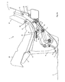
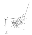
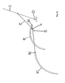
- the Fig. 1a shows a schematic side view of a motor vehicle seat according to a first embodiment of the present invention in a position of use.
- the motor vehicle seat generally designated 1 (hereinafter abbreviated to "seat") is according to the Fig. 1a exemplified as a rear seat, which is attached via the schematically illustrated anchoring element 7 on the vehicle floor 8.
- the seat 1 comprises a seat part 2 with a padding 20 and a backrest 3 with a padding 21.
- the backrest 3 is inclined at an acute angle to the rear and the seat part 2 with the padding 20 inclined at an acute angle obliquely backwards.
- the backrest 3 can be pivoted about the pivot axis 23 and folded forward.
- the seat part 2 is in the in the Fig. 1a locked position of use and thus can not be pivoted forward and / or lowered in the position of use.
- a lever element designed as a locking element 16 is provided which has a locking claw in a known manner, which engages in a body-mounted locking lug or a body-mounted locking bolt.
- the locking lever 16 is pivotable about the lower pivot axis 11.
- the function of adjusting the angle of inclination of the backrest 3 is decoupled from the function of pivoting and lowering the seat part 2, which will be explained in more detail below.
- a locking mechanism may be provided. An example of such a locking mechanism is exemplified in FIG Fig. 6 shown.
- a locking lever 31 is provided which is pivotable about the pivot axis 32 and at its lower edge has a comb-like configuration in the form of a plurality of preferably equidistantly spaced recesses 33 has.
- To set the angle of inclination of the backrest 3 engages one of the recesses 33 of the locking lever 31 in the known manner in a body-fixed bolt or locking latch.
- a rotary wheel or the like may be provided for adjusting the angle of inclination of the backrest 3 in order to move the backrest 3 about the pivot axis 23 (FIG. Fig. 1a ) to swing.
- the backrest 3 By releasing the locking mechanism, in particular by releasing the in the Fig. 6 illustrated locking lever 31, the backrest 3 is released and the backrest 3 can be folded to the seat part. According to the invention, no cable or the like is actuated for unlocking the seat part 2 when releasing the locking mechanism of the backrest 3.
- a pivot lever means which comprises a front adjusting lever 4 and a rear adjusting lever 9.
- the front adjustment lever 4 is pivotable about the lower pivot axis 5 of the body-fixed anchoring element 7 and is articulated in the region of the upper pivot axis 6 to the seat part 2.
- the rear adjustment lever 9 is pivotable about the body-fixed lower pivot axis 11 and is articulated in the region of the upper pivot axis 10 to the seat part 2.
- the seat part 2 is formed as a rigid linkage, which connects the upper pivot axes 6, 10 with each other.
- a further front adjusting lever and a further rear adjusting lever 9 can be provided in a comparable manner.
- a coupling lever 12 is provided, one end of which is pivotable about the pivot axis 13, which is arranged on the side cheek 22 of the backrest 3 spaced from the pivot axis 23 of the backrest 3, and at its other end Slot 15 is formed to couple the coupling lever 12 with the rear adjusting lever 9 via a rotary sliding joint.
- Fig. 1a 9 is a pin 14 or a similar projection formed on the outside of the rear adjusting lever, which engages in the slot 15 and is guided in this.
- the pin 14 or the projection is spaced from the lower pivot axis 11 of the rear adjusting lever 9 to form a rotary sliding joint.
- the rear adjusting lever 9 between the locking lever 16 and the coupling lever 12 is arranged.
- a pin 18 projecting inwardly is formed, which in the position of use according to FIG Fig. 1a is not applied to the inclined contact surface 25 of the locking lever 16.
- a Wegauseffect projecting pin 17 is provided at the free end of the locking lever 16 .
- a tension spring 19 is hooked to couple the coupling lever 12 with the locking lever 16 and bias against each other.
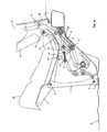
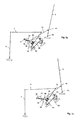
- Fig. 1b a second embodiment of a motor vehicle seat according to the invention in the same position as in the Fig. 1a to be discribed.
- Fig. 1b are the predominantly used for the seat adjustment of the seat part, in particular the adjusting lever, shown schematically as line connections to explain further details of an exemplary locking mechanism for locking the seat part.
- FIGS. 1a and 1b Denote identical reference numerals identical elements, the description of which will be omitted hereinafter.
- the locking mechanism for locking the seat part 2 has a first locking lever 50 and a second lever 55 which are each pivotable about a body-fixed axis 61 and 11, respectively.
- a receptacle for receiving and locking the locking bolt 51 is provided at the rear end.
- the front actuating end 52 of the locking lever 50 abuts against a lug 58 of the second lever 55.
- Fig. 1b is the pin 18 via a connecting element 56, such as a driver or a neck, connected to the coupling lever 12 and the engaging in the slot 15 pin 14 is connected via a corresponding connecting element 57 with the rear adjusting lever 9.
- the pin 18 is connected via the biased in the locking direction spring 19 with the pin 17 to couple the coupling lever with the second lever 55.
- the backrest 3 assumes the predetermined angle of inclination.
- the pin 14 is not yet in contact with the upper end of the slot 15, but rather an overstroke or gap 24 between the pin 14 and the upper end of the slot 15 is formed, which to compensate for manufacturing tolerances and the like serves.
- the Fig. 3b shows the motor vehicle seat according to the second embodiment in a position in which the locking pin 51 is released.
- the Fig. 3b has the pin 18, in contact with the abutment surface 25, the second lever 55 pivoted counterclockwise far enough that the operating end 52 of the locking lever 50 has slid over the projection 58 of the locking lever 50 and slid down on the curved flank of the projection 58.
- the locking lever 50 which is biased by the torsion spring 60 in the release position, pivoted counterclockwise, so that the receptacle at the rear end of the locking lever 50 finally releases the locking pin 51 so as to unlock the seat part 2.
- the pin 14 Upon further folding the backrest 3, the pin 14 finally comes into abutment with the upper end of the oblong hole 15, so that the coupling lever 12 presses the pin 14 downwardly via the rotary sliding joint described above and thus pivots the rear adjusting lever 9 counterclockwise.
- the inwardly projecting pin 18 slides on the coupling lever 12 on the contact surface 25 of the locking lever 16 and the locking lever 16 is further pivoted counterclockwise about the pivot axis 11, without being in engagement with a locking element.
- Due to the special design of the front adjusting lever 4 and the rear adjusting lever 9 to a pivot lever device ensures that the seat part 2 is upstream with the padding 20 during the further forward pivoting of the backrest 3 and lowered.
- the Fig. 4a shows the motor vehicle seat in an intermediate position with pre-folded backrest. 3
- the second lever 55 is further pre-pivoted in the counterclockwise direction and begins the seat part 2 so as to lower in addition to the pivoting movement.
- the operating end 52 remains at the lower end of the second lever 55, so that the angular position of the locking lever 50 with the receptacle 54 for the locking bolt virtually no longer changes.
- the locking bolt is connected via a connecting element 53 with the rear adjusting lever 9, so that according to the second embodiment, no body-locking bolt is required.
- the steps described above are performed in reverse order, so the backrest 3 is folded up clockwise until finally the locking lever 16 again the position according to the Fig. 2 occupies, in which the seat part 2 is locked.
- the backrest 3 In the locked position of the seat part 2, the backrest 3 can be further freely pivoted backwards until finally by locking the backrest 3, for example by means of in the Fig. 6 shown locking lever 31, the angle of inclination of the backrest 3 is fixed.
- Fig. 1 to 5b can be readily removed, the locking lever 16 and 50 is actuated automatically and without actuation of other elements, such as a cable known from the prior art, of the coupling lever 12.
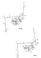
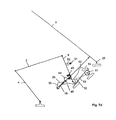
- FIGS. 7a-7d show a motor vehicle seat according to a third embodiment of the present invention in the movement phases according to the Fig. 1a-4a or 1b-4b.
- the essential levers are indicated schematically only as line connections to facilitate understanding.
- the same reference numerals designate the same elements as described above with reference to FIG Fig. 1 to 6 described so that their description can be omitted below.
- the coupling lever 12 is formed as a two-part lever, which is connected to the hinge axes 41 and 43 with the backrest 3 and the rear lever 9 and a further hinge axis 42, to which the spring 19 is coupled, for example via a pin or the like ,
- the locking mechanism is formed similar to the second embodiment and comprises a locking lever 50 and a second lever 55.
- Fig. 7a is the arm 46 of the coupling lever 12 to the upper driver 45, which is connected to the rear lever 9.
- the driver 45 can thus be used to return the seat part 2 when folding back the backrest 3.
- FIGS. 7a-7d can be removed, the rear lever 9 when folding back the backrest 3 from the lowered position back into the position of use according to the Fig. 7a taken from the driver 45 which bears against the arm 46 of the coupling lever 12.
- the coupling lever 12 and the rear adjusting lever 9 are biased against each other, for example by means of the tension spring 19.
- the locking element 40 according to the third embodiment may of course also be a body-locking bolt, which is depressed by the rocker arm 12 or by a coupled thereto element.
- a locking element according to the third embodiment also carried or by a locking lever, not shown, for example in the reference to the Fig. 1 to 5b described above, are released.
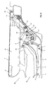
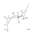
- FIGS. 8a to 8c show in a juxtaposition further possible embodiments with at least one guide slot for guiding the seat part during pre-storage and lowering of the seat part.
- an arcuate guide slot 80 is provided in which an element, for example a pin 85, engages the rear end of the seat part 2.
- the guide slot 80 is fixed to the body, for example, in a vehicle fixed firmly attached side part (not shown).
- the front adjusting lever 4 is pivoted about the lower pivot axis 5 when the backrest 3 is folded forward, thus lowering the seat part 2.
- a slot 15 is formed, in which in the manner described above a pin 14 engages, which is coupled to the seat part 2.
- the front end of the coupling lever 12 is articulated directly to the seat part 2.
- the Fig. 8c are two arcuate guide slots 81 and 82 are provided, in which connected to the seat part 2 pins 85 and 86 engage to guide the movement of the seat part 2 when folding the backrest 3.
- guide slots can be combined with other adjustment mechanisms, such as pivoting lever means, in a suitable manner to suitably control the sequence of movement in folding the backrest forward.
- the guide slots described to be arcuate may also be formed in other ways to suitably guide the movement of the seat portion, for example in the form of substantially linearly obliquely downwardly extending guide slots.
Landscapes
- Engineering & Computer Science (AREA)
- Aviation & Aerospace Engineering (AREA)
- Transportation (AREA)
- Mechanical Engineering (AREA)
- Seats For Vehicles (AREA)
Applications Claiming Priority (2)
| Application Number | Priority Date | Filing Date | Title |
|---|---|---|---|
| DE10355765 | 2003-11-26 | ||
| DE10355765A DE10355765A1 (de) | 2003-11-26 | 2003-11-26 | Kraftfahrzeugsitz |
Publications (3)
| Publication Number | Publication Date |
|---|---|
| EP1535792A2 EP1535792A2 (de) | 2005-06-01 |
| EP1535792A3 EP1535792A3 (de) | 2007-06-27 |
| EP1535792B1 true EP1535792B1 (de) | 2009-03-04 |
Family
ID=34442344
Family Applications (1)
| Application Number | Title | Priority Date | Filing Date |
|---|---|---|---|
| EP04106049A Expired - Lifetime EP1535792B1 (de) | 2003-11-26 | 2004-11-24 | Kraftfahrzeugsitz |
Country Status (4)
| Country | Link |
|---|---|
| US (1) | US7134725B2 (enExample) |
| EP (1) | EP1535792B1 (enExample) |
| JP (1) | JP3971765B2 (enExample) |
| DE (2) | DE10355765A1 (enExample) |
Families Citing this family (31)
| Publication number | Priority date | Publication date | Assignee | Title |
|---|---|---|---|---|
| DE102004007863A1 (de) * | 2004-02-17 | 2005-09-08 | Johnson Controls Gmbh | Fahrzeugsitz, insbesondere für ein Kraftfahrzeug, mit einer klappbaren Lehne und einer klappbaren Sitzbasis und Verfahren |
| DE102004057471B4 (de) * | 2004-11-21 | 2010-09-23 | Bayerische Motoren Werke Aktiengesellschaft | Fahrzeugsitz, insbesondere Kraftfahrzeugsitz |
| US20060267366A1 (en) * | 2005-05-16 | 2006-11-30 | Johnson Controls Technology Company | 4-Bar freeplay cam |
| DE102005023563A1 (de) * | 2005-05-18 | 2006-11-23 | Intier Automotive Seating Systems Gmbh | Fahrzeugsitz |
| CN101193771B (zh) * | 2005-06-09 | 2010-11-03 | 英提尔汽车公司 | 单腿转换座椅 |
| DE102005029668A1 (de) * | 2005-06-22 | 2006-12-28 | Sitech Sitztechnik Gmbh | Verriegelung eines Kraftfahrzeugsitzes im Gelenkmechanismus (Lehne-Sitz) über einen Kniehebel |
| DE602006019181D1 (de) * | 2005-09-20 | 2011-02-10 | Mazda Motor | Vorrichtung für Kraftfahrzeugsitze |
| DE102006001013A1 (de) | 2006-01-05 | 2007-07-12 | Intier Automotive Seating Systems Gmbh | Kraftfahrzeugsitz mit einer Kopplung zwischen der Rückenlehnen- und der Sitzbewegung und Kraftfahrzeug mit einem solchen Kraftfahrzeugsitz |
| FR2899527B1 (fr) * | 2006-04-11 | 2008-06-20 | Faurecia Sieges Automobile | Agencement d'un siege de vehicule automobile pour en permettre le rangement dans un compartiment du plancher du dit vehicule, et vehicule adapte |
| JP4176118B2 (ja) * | 2006-07-31 | 2008-11-05 | トヨタ自動車株式会社 | 車両用シート装置 |
| CA2712004C (en) * | 2008-03-20 | 2017-07-18 | Magna Seating Inc. | Second row front tumble hook protection |
| EP2263912A4 (en) * | 2008-03-24 | 2011-05-18 | Ts Tech Co Ltd | SEAT LATCH DEVICE AND RETRACTABLE VEHICLE SEAT |
| WO2011002027A1 (ja) * | 2009-07-03 | 2011-01-06 | テイ・エス テック株式会社 | 乗物用シート |
| DE102009037816B3 (de) * | 2009-08-12 | 2010-10-28 | Keiper Gmbh & Co. Kg | Fahrzeugsitz, insbesondere Kraftfahrzeugsitz |
| CN103052532B (zh) * | 2010-08-04 | 2016-01-20 | 约翰逊控股公司 | 用于车座的固定装置和车座 |
| WO2012093635A1 (ja) * | 2011-01-07 | 2012-07-12 | テイ・エス テック株式会社 | 格納式リアシート |
| WO2012174654A1 (en) | 2011-06-23 | 2012-12-27 | Magna Seating Inc. | Stow-in-floor seat assembly |
| KR101337935B1 (ko) | 2011-11-04 | 2013-12-09 | 포레시아오토모티브시팅코리아 유한회사 | 차량용 시트 장치 |
| DE102013221132B4 (de) * | 2013-10-17 | 2021-09-09 | Brose Fahrzeugteile SE & Co. Kommanditgesellschaft, Coburg | Fahrzeugsitz mit einem über ein Koppelelement mit einem Beschlaghebel gekoppelten Betätigungselement |
| CN105658478A (zh) * | 2013-12-27 | 2016-06-08 | 提爱思科技股份有限公司 | 交通工具用座椅 |
| JP6237465B2 (ja) | 2014-05-23 | 2017-11-29 | トヨタ紡織株式会社 | 乗物用シート |
| JP6113115B2 (ja) * | 2014-06-23 | 2017-04-12 | 株式会社クボタ | シート装置 |
| US9944204B2 (en) * | 2016-01-07 | 2018-04-17 | Toyota Motor Engineering & Manufacturing North America, Inc. | Rear seat having two independent modes |
| US10336222B2 (en) | 2016-06-23 | 2019-07-02 | Magna Seating Inc | Stow-in-floor seat assembly with pitched easy entry position |
| WO2018046433A1 (de) * | 2016-09-08 | 2018-03-15 | Adient Luxembourg Holding S.à.r.l. | Fahrzeugsitz |
| DE102016224625A1 (de) * | 2016-12-09 | 2018-06-14 | Brose Fahrzeugteile Gmbh & Co. Kg, Coburg | Fahrzeugsitz mit Sperrmechanimus zur Sperrung eines zumindest abschnittsweise absenkbaren Polsterträgers bei einer Verstellung einer Rückenlehne |
| DE102017218125A1 (de) * | 2017-10-11 | 2019-04-11 | Volkswagen Aktiengesellschaft | Fahrzeugsitz mit einem Easy-Entry-Mechanismus |
| US10442322B2 (en) | 2017-11-17 | 2019-10-15 | Brose Fahrzeugteile Gmbh & Co. Kommanditgesellschaft | Easy-entry vehicle seat |
| US10589642B2 (en) | 2017-11-15 | 2020-03-17 | Brose Fahrzeugteile Gmbh & Co. Kommanditgesellschaft, Coburg | Easy-entry vehicle seat |
| CA3191360A1 (en) | 2022-03-18 | 2023-09-18 | 13872548 Canada Inc. | Display case and method of assembly |
| US12583369B2 (en) * | 2023-11-03 | 2026-03-24 | Atieva, Inc. | Stowing vehicle seat with break link mechanism |
Family Cites Families (31)
| Publication number | Priority date | Publication date | Assignee | Title |
|---|---|---|---|---|
| US4597321A (en) * | 1982-11-19 | 1986-07-01 | Gabelish Peter W | Rotary valve |
| US4957321A (en) * | 1988-10-12 | 1990-09-18 | Ford Motor Company | Stowable vehicle seat with seat back position controller |
| US4869541A (en) * | 1988-12-27 | 1989-09-26 | Lear Siegler Seating Corporation | Forwardly pivotal seat assembly |
| US5536069A (en) * | 1993-10-12 | 1996-07-16 | Ford Motor Company | Rotary action switch assembly |
| US5527087A (en) * | 1993-10-28 | 1996-06-18 | Aisin Seiki Kabushiki Kaisha | Vehicle seat apparatus including a locking mechanism |
| CA2111725C (en) * | 1993-12-18 | 1998-10-13 | Wojciech Smuk | Combination reclining and folding mechanism for automotive seat assemblies |
| JPH08258600A (ja) * | 1995-03-21 | 1996-10-08 | Aisin Seiki Co Ltd | 車両用シート装置 |
| DE19533932C2 (de) | 1995-09-13 | 1999-03-11 | Lear Corp | Sitz, insbesondere Fondsitz für Kraftfahrzeuge |
| US5570931A (en) * | 1995-09-29 | 1996-11-05 | Chrysler Corporation | Vehicle adjustable and stowable rear seat |
| DE19616070C2 (de) * | 1996-04-23 | 1998-03-19 | Keiper Recaro Gmbh Co | Kraftfahrzeugsitz |
| US5871255A (en) * | 1997-01-06 | 1999-02-16 | Chrysler Corporation | Vehicle seat |
| US6039401A (en) * | 1997-07-28 | 2000-03-21 | Lear Corporation | Self-latching and self-releasing latch mechanism for removable seat |
| US6279982B1 (en) * | 1998-05-13 | 2001-08-28 | Toyota Jidosha Kabushiki Kaisha | Vehicle seat storing device |
| DE19904009C1 (de) | 1999-02-02 | 2000-05-31 | Faure Bertrand Sitztech Gmbh | Kraftfahrzeug-Rücksitz mit klappbarer Rückenlehne und absenkbarem Sitzteil |
| JP3810944B2 (ja) * | 1999-05-21 | 2006-08-16 | 株式会社大井製作所 | シートバックのロック装置 |
| US6123380A (en) * | 1999-06-11 | 2000-09-26 | Lear Corporation | Automotive seat assembly with folding structural supports for storage in a foot well for an automotive vehicle body |
| DE19932214B4 (de) | 1999-07-09 | 2011-12-29 | Lear Corp. | Fahrzeugsitz |
| JP3635292B2 (ja) * | 1999-08-10 | 2005-04-06 | トヨタ紡織株式会社 | 車両用リヤシート |
| US6644730B2 (en) * | 2000-06-08 | 2003-11-11 | Takashimaya Nippatsu Kogyo Co., Ltd. | Storage type seat for automobile and seat storage structure |
| US7021716B2 (en) * | 2001-07-06 | 2006-04-04 | Intier Automotive Inc. | Tip easy entry and fold flat recliner assembly |
| DE20114059U1 (de) * | 2001-08-25 | 2003-01-16 | Johnson Controls GmbH, 51399 Burscheid | Fahrzeugsitz |
| JP3647408B2 (ja) * | 2001-10-16 | 2005-05-11 | 本田技研工業株式会社 | 車両のシート構成 |
| DE10228465A1 (de) * | 2002-06-26 | 2004-01-15 | Bayerische Motoren Werke Ag | Kraftfahrzeug |
| KR100461102B1 (ko) * | 2002-08-08 | 2004-12-13 | 현대자동차주식회사 | 차량용 리어시트의 리클라이닝 장치 |
| DE10236490B4 (de) * | 2002-08-09 | 2005-06-23 | Faurecia Autositze Gmbh & Co. Kg | Kraftfahrzeugsitz |
| JP3878099B2 (ja) * | 2002-09-19 | 2007-02-07 | 本田技研工業株式会社 | 車両用シート配列構造 |
| JP4105534B2 (ja) * | 2002-11-28 | 2008-06-25 | トヨタ紡織株式会社 | 車両用シート |
| FR2851211B1 (fr) * | 2003-02-19 | 2006-01-13 | Faurecia Sieges Automobile | Siege rabattable et vehicule comportant un tel siege |
| DE10317238A1 (de) * | 2003-04-10 | 2004-10-28 | Brose Fahrzeugteile Gmbh & Co. Kommanditgesellschaft, Coburg | Kraftfahrzeugsitz |
| FR2856963B1 (fr) * | 2003-07-03 | 2006-09-01 | Antolin Grupo Ing Sa | Siege de vehicule automobile |
| US6997498B2 (en) * | 2003-07-23 | 2006-02-14 | Honda Motor Co., Ltd. | Seat device for vehicle |
-
2003
- 2003-11-26 DE DE10355765A patent/DE10355765A1/de not_active Withdrawn
-
2004
- 2004-11-15 US US10/989,716 patent/US7134725B2/en not_active Expired - Lifetime
- 2004-11-24 DE DE502004009078T patent/DE502004009078D1/de not_active Expired - Lifetime
- 2004-11-24 EP EP04106049A patent/EP1535792B1/de not_active Expired - Lifetime
- 2004-11-26 JP JP2004342543A patent/JP3971765B2/ja not_active Expired - Fee Related
Also Published As
| Publication number | Publication date |
|---|---|
| DE502004009078D1 (de) | 2009-04-16 |
| JP2005153874A (ja) | 2005-06-16 |
| DE10355765A1 (de) | 2005-06-30 |
| US20050110323A1 (en) | 2005-05-26 |
| US7134725B2 (en) | 2006-11-14 |
| EP1535792A3 (de) | 2007-06-27 |
| JP3971765B2 (ja) | 2007-09-05 |
| EP1535792A2 (de) | 2005-06-01 |
Similar Documents
| Publication | Publication Date | Title |
|---|---|---|
| EP1535792B1 (de) | Kraftfahrzeugsitz | |
| EP1165342B1 (de) | Kraftfahrzeugsitz | |
| DE10256514B4 (de) | Fahrzeugsitz, insbesondere Sitz einer hinteren Sitzreihe eines Fahrzeugs | |
| DE102016202513B4 (de) | Fahrzeugsitz, insbesondere Kraftfahrzeugsitz | |
| DE102015218873B4 (de) | Fahrzeugsitz | |
| DE102011087175A1 (de) | Fahrzeugsitz | |
| EP2284039A1 (de) | Fahrzeugsitz, insbesondere Kraftfahrzeugsitz | |
| DE10139538C1 (de) | Fondsitz für Kraftfahrzeuge | |
| WO2016001096A1 (de) | Lehnenversteller für einen sitz und fahrzeugsitz | |
| DE102017215929A1 (de) | Vorschwenkbarer Fahrzeugsitz | |
| DE3517877A1 (de) | Einstellbare sitzanordnung | |
| EP2956333B1 (de) | Rastbeschlag für einen fahrzeugsitz sowie fahrzeugsitz | |
| DE19758237A1 (de) | Kraftfahrzeugsitz | |
| DE102007036450B3 (de) | Fahrzeugsitz, insbesondere Kraftfahrzeugsitz | |
| WO2021214127A1 (de) | Fahrzeugsitz mit einem kinematikhebel | |
| EP1658194A2 (de) | Kraftfahrzeugsitz | |
| EP3694744B1 (de) | Fahrzeugsitz mit einem easy-entry-mechanismus | |
| DE102004051873B4 (de) | Kraftfahrzeugsitz | |
| DE10353242B3 (de) | Fahrzeugsitz | |
| DE102015201362B4 (de) | Fahrzeugsitz, insbesondere Kraftfahrzeugsitz, mit Koppelvorrichtung | |
| DE102014214564B4 (de) | Fahrzeugsitz, insbesondere Kraftfahrzeugsitz | |
| DE102004024225B3 (de) | Fahrzeugsitz | |
| DE10227945B4 (de) | Fahrzeugsitz | |
| DE102005024939B4 (de) | Kraftfahrzeugsitz mit einer vorklappbar an einem Sitzteil angelenkten Rückenlehne | |
| WO2022090984A1 (de) | Fahrzeugsitz |
Legal Events
| Date | Code | Title | Description |
|---|---|---|---|
| PUAI | Public reference made under article 153(3) epc to a published international application that has entered the european phase |
Free format text: ORIGINAL CODE: 0009012 |
|
| AK | Designated contracting states |
Kind code of ref document: A2 Designated state(s): AT BE BG CH CY CZ DE DK EE ES FI FR GB GR HU IE IS IT LI LU MC NL PL PT RO SE SI SK TR |
|
| AX | Request for extension of the european patent |
Extension state: AL HR LT LV MK YU |
|
| PUAL | Search report despatched |
Free format text: ORIGINAL CODE: 0009013 |
|
| AK | Designated contracting states |
Kind code of ref document: A3 Designated state(s): AT BE BG CH CY CZ DE DK EE ES FI FR GB GR HU IE IS IT LI LU MC NL PL PT RO SE SI SK TR |
|
| AX | Request for extension of the european patent |
Extension state: AL HR LT LV MK YU |
|
| 17P | Request for examination filed |
Effective date: 20070810 |
|
| AKX | Designation fees paid |
Designated state(s): DE ES FR |
|
| AXX | Extension fees paid |
Extension state: MK Payment date: 20071227 Extension state: LV Payment date: 20071227 Extension state: LT Payment date: 20071227 Extension state: HR Payment date: 20071227 Extension state: AL Payment date: 20071227 Extension state: YU Payment date: 20071227 |
|
| GRAP | Despatch of communication of intention to grant a patent |
Free format text: ORIGINAL CODE: EPIDOSNIGR1 |
|
| GRAS | Grant fee paid |
Free format text: ORIGINAL CODE: EPIDOSNIGR3 |
|
| GRAA | (expected) grant |
Free format text: ORIGINAL CODE: 0009210 |
|
| AK | Designated contracting states |
Kind code of ref document: B1 Designated state(s): DE ES FR |
|
| AX | Request for extension of the european patent |
Extension state: AL HR LT LV MK YU |
|
| REF | Corresponds to: |
Ref document number: 502004009078 Country of ref document: DE Date of ref document: 20090416 Kind code of ref document: P |
|
| RAP2 | Party data changed (patent owner data changed or rights of a patent transferred) |
Owner name: BROSE FAHRZEUGTEILE GMBH & CO. KG |
|
| LTIE | Lt: invalidation of european patent or patent extension |
Effective date: 20090304 |
|
| PG25 | Lapsed in a contracting state [announced via postgrant information from national office to epo] |
Ref country code: ES Free format text: LAPSE BECAUSE OF FAILURE TO SUBMIT A TRANSLATION OF THE DESCRIPTION OR TO PAY THE FEE WITHIN THE PRESCRIBED TIME-LIMIT Effective date: 20090615 |
|
| PLBE | No opposition filed within time limit |
Free format text: ORIGINAL CODE: 0009261 |
|
| STAA | Information on the status of an ep patent application or granted ep patent |
Free format text: STATUS: NO OPPOSITION FILED WITHIN TIME LIMIT |
|
| 26N | No opposition filed |
Effective date: 20091207 |
|
| REG | Reference to a national code |
Ref country code: FR Ref legal event code: PLFP Year of fee payment: 12 |
|
| REG | Reference to a national code |
Ref country code: FR Ref legal event code: PLFP Year of fee payment: 13 |
|
| REG | Reference to a national code |
Ref country code: FR Ref legal event code: PLFP Year of fee payment: 14 |
|
| REG | Reference to a national code |
Ref country code: FR Ref legal event code: PLFP Year of fee payment: 15 |
|
| PGFP | Annual fee paid to national office [announced via postgrant information from national office to epo] |
Ref country code: FR Payment date: 20181011 Year of fee payment: 15 |
|
| REG | Reference to a national code |
Ref country code: DE Ref legal event code: R082 Ref document number: 502004009078 Country of ref document: DE Representative=s name: 2K PATENTANWAELTE BLASBERG KEWITZ & REICHEL PA, DE Ref country code: DE Ref legal event code: R081 Ref document number: 502004009078 Country of ref document: DE Owner name: BROSE FAHRZEUGTEILE SE & CO. KOMMANDITGESELLSC, DE Free format text: FORMER OWNER: BROSE FAHRZEUGTEILE GMBH & CO. KOMMANDITGESELLSCHAFT, COBURG, 96450 COBURG, DE |
|
| PG25 | Lapsed in a contracting state [announced via postgrant information from national office to epo] |
Ref country code: FR Free format text: LAPSE BECAUSE OF NON-PAYMENT OF DUE FEES Effective date: 20191130 |
|
| PGFP | Annual fee paid to national office [announced via postgrant information from national office to epo] |
Ref country code: DE Payment date: 20201130 Year of fee payment: 17 |
|
| REG | Reference to a national code |
Ref country code: DE Ref legal event code: R119 Ref document number: 502004009078 Country of ref document: DE |
|
| PG25 | Lapsed in a contracting state [announced via postgrant information from national office to epo] |
Ref country code: DE Free format text: LAPSE BECAUSE OF NON-PAYMENT OF DUE FEES Effective date: 20220601 |