US7134725B2 - Motor vehicle seat - Google Patents
Motor vehicle seat Download PDFInfo
- Publication number
- US7134725B2 US7134725B2 US10/989,716 US98971604A US7134725B2 US 7134725 B2 US7134725 B2 US 7134725B2 US 98971604 A US98971604 A US 98971604A US 7134725 B2 US7134725 B2 US 7134725B2
- Authority
- US
- United States
- Prior art keywords
- seat part
- backrest
- locking
- lever
- seat
- Prior art date
- Legal status (The legal status is an assumption and is not a legal conclusion. Google has not performed a legal analysis and makes no representation as to the accuracy of the status listed.)
- Expired - Lifetime
Links
Images


Classifications
-
- B—PERFORMING OPERATIONS; TRANSPORTING
- B60—VEHICLES IN GENERAL
- B60N—SEATS SPECIALLY ADAPTED FOR VEHICLES; VEHICLE PASSENGER ACCOMMODATION NOT OTHERWISE PROVIDED FOR
- B60N2/00—Seats specially adapted for vehicles; Arrangement or mounting of seats in vehicles
- B60N2/02—Seats specially adapted for vehicles; Arrangement or mounting of seats in vehicles the seat or part thereof being movable, e.g. adjustable
- B60N2/22—Seats specially adapted for vehicles; Arrangement or mounting of seats in vehicles the seat or part thereof being movable, e.g. adjustable the back-rest being adjustable
- B60N2/2245—Seats specially adapted for vehicles; Arrangement or mounting of seats in vehicles the seat or part thereof being movable, e.g. adjustable the back-rest being adjustable provided with a lock mechanism on the upper part of the back-rest
-
- B—PERFORMING OPERATIONS; TRANSPORTING
- B60—VEHICLES IN GENERAL
- B60N—SEATS SPECIALLY ADAPTED FOR VEHICLES; VEHICLE PASSENGER ACCOMMODATION NOT OTHERWISE PROVIDED FOR
- B60N2/00—Seats specially adapted for vehicles; Arrangement or mounting of seats in vehicles
- B60N2/24—Seats specially adapted for vehicles; Arrangement or mounting of seats in vehicles for particular purposes or particular vehicles
- B60N2/30—Non-dismountable or dismountable seats storable in a non-use position, e.g. foldable spare seats
- B60N2/3002—Non-dismountable or dismountable seats storable in a non-use position, e.g. foldable spare seats back-rest movements
- B60N2/3004—Non-dismountable or dismountable seats storable in a non-use position, e.g. foldable spare seats back-rest movements by rotation only
- B60N2/3009—Non-dismountable or dismountable seats storable in a non-use position, e.g. foldable spare seats back-rest movements by rotation only about transversal axis
- B60N2/3013—Non-dismountable or dismountable seats storable in a non-use position, e.g. foldable spare seats back-rest movements by rotation only about transversal axis the back-rest being hinged on the vehicle frame
-
- B—PERFORMING OPERATIONS; TRANSPORTING
- B60—VEHICLES IN GENERAL
- B60N—SEATS SPECIALLY ADAPTED FOR VEHICLES; VEHICLE PASSENGER ACCOMMODATION NOT OTHERWISE PROVIDED FOR
- B60N2/00—Seats specially adapted for vehicles; Arrangement or mounting of seats in vehicles
- B60N2/24—Seats specially adapted for vehicles; Arrangement or mounting of seats in vehicles for particular purposes or particular vehicles
- B60N2/30—Non-dismountable or dismountable seats storable in a non-use position, e.g. foldable spare seats
- B60N2/3038—Cushion movements
- B60N2/3063—Cushion movements by composed movement
- B60N2/3065—Cushion movements by composed movement in a longitudinal-vertical plane
-
- B—PERFORMING OPERATIONS; TRANSPORTING
- B60—VEHICLES IN GENERAL
- B60N—SEATS SPECIALLY ADAPTED FOR VEHICLES; VEHICLE PASSENGER ACCOMMODATION NOT OTHERWISE PROVIDED FOR
- B60N2/00—Seats specially adapted for vehicles; Arrangement or mounting of seats in vehicles
- B60N2/24—Seats specially adapted for vehicles; Arrangement or mounting of seats in vehicles for particular purposes or particular vehicles
- B60N2/30—Non-dismountable or dismountable seats storable in a non-use position, e.g. foldable spare seats
- B60N2/3072—Non-dismountable or dismountable seats storable in a non-use position, e.g. foldable spare seats on a lower level of a multi-level vehicle floor
-
- B—PERFORMING OPERATIONS; TRANSPORTING
- B60—VEHICLES IN GENERAL
- B60N—SEATS SPECIALLY ADAPTED FOR VEHICLES; VEHICLE PASSENGER ACCOMMODATION NOT OTHERWISE PROVIDED FOR
- B60N2/00—Seats specially adapted for vehicles; Arrangement or mounting of seats in vehicles
- B60N2/24—Seats specially adapted for vehicles; Arrangement or mounting of seats in vehicles for particular purposes or particular vehicles
- B60N2/30—Non-dismountable or dismountable seats storable in a non-use position, e.g. foldable spare seats
- B60N2/3088—Non-dismountable or dismountable seats storable in a non-use position, e.g. foldable spare seats characterised by the mechanical link
- B60N2/309—Non-dismountable or dismountable seats storable in a non-use position, e.g. foldable spare seats characterised by the mechanical link rods
-
- B—PERFORMING OPERATIONS; TRANSPORTING
- B60—VEHICLES IN GENERAL
- B60N—SEATS SPECIALLY ADAPTED FOR VEHICLES; VEHICLE PASSENGER ACCOMMODATION NOT OTHERWISE PROVIDED FOR
- B60N2/00—Seats specially adapted for vehicles; Arrangement or mounting of seats in vehicles
- B60N2/24—Seats specially adapted for vehicles; Arrangement or mounting of seats in vehicles for particular purposes or particular vehicles
- B60N2/30—Non-dismountable or dismountable seats storable in a non-use position, e.g. foldable spare seats
- B60N2/3088—Non-dismountable or dismountable seats storable in a non-use position, e.g. foldable spare seats characterised by the mechanical link
- B60N2/3093—Non-dismountable or dismountable seats storable in a non-use position, e.g. foldable spare seats characterised by the mechanical link slides
-
- B—PERFORMING OPERATIONS; TRANSPORTING
- B60—VEHICLES IN GENERAL
- B60N—SEATS SPECIALLY ADAPTED FOR VEHICLES; VEHICLE PASSENGER ACCOMMODATION NOT OTHERWISE PROVIDED FOR
- B60N2/00—Seats specially adapted for vehicles; Arrangement or mounting of seats in vehicles
- B60N2/24—Seats specially adapted for vehicles; Arrangement or mounting of seats in vehicles for particular purposes or particular vehicles
- B60N2/32—Seats specially adapted for vehicles; Arrangement or mounting of seats in vehicles for particular purposes or particular vehicles convertible for other use
- B60N2/36—Seats specially adapted for vehicles; Arrangement or mounting of seats in vehicles for particular purposes or particular vehicles convertible for other use into a loading platform
Definitions
- the present invention relates to a motor vehicle seat, in particular a motor vehicle rear seat for the second or third row of seats of a motor vehicle.
- Such a motor vehicle seat designed as the middle part of a rear seat is disclosed in DE 100 55 205 A1.
- the seat part is mounted such that it can be moved in a pivoting manner by means of a front and a rear pivot lever device between a seat position and a flat position in which it is moved forward and lowered.
- the backrest is connected to the seat part by means of a connecting lever device such that the seat part assumes the raised seat position in the folded-up position of the backrest and assumes the lowered flat position or storing position in the folded-forward position.
- the connecting lever device comprises a two-arm lever element, a connecting lever element and a coupling lever element.
- the connecting lever device is arrested in the use position of the seat part and is released by actuating a cable pull. Unlocking thus requires a Bowden cable system so that the structure as a whole is relatively complex.
- the Bowden cable system requires additional components, and this increases the costs of a motor vehicle seat.
- DE 199 32 214 A1 discloses a vehicle seat in which the seat part can be moved forward as the backrest is folded down from an articulation point of the backrest.
- the backrest can be folded down toward the seat part only following actuation of an unlocking button which releases a safety catch.
- an unlocking button which releases a safety catch.
- the backrest is unlocked and on the other hand a clip is released so that the seat part can move forward.
- a mechanism with a cable pull and a spring that is not continuously biased is provided, and this mechanism is relatively complex. Without prior actuation of the unlocking button, the inclination of the backrest can be changed only by turning a hand-wheel.
- DE 199 04 009 C1 discloses a motor vehicle rear seat with a foldable backrest and a seat part that can be lowered.
- the seat part is mounted pivotably on an intermediate frame which in turn is mounted pivotably on the floor of the vehicle.
- the backrest is coupled by means of a mechanical coupling element to a rod system which couples the seat part to the intermediate frame such that it can be moved in a pivoting manner.
- the seat as a whole can be moved forward only when it is unlocked centrally by means of a handle.
- the seat is relatively complex and is composed of a large number of elements.
- DE 195 33 932 A1 discloses a front seat for motor vehicles in which the backrest is articulated pivotably on a carriage, wherein the carriage is mounted such that it can be displaced longitudinally and on a carriage guide fixed to the floor of the vehicle.
- the seat part is first pivoted forward and then the backrest with the carriage is pushed forward to come to bear against the forward-pivoted seat part.
- a central locking hook is provided which unlocks the seat by actuating a cable pull. Additional locking elements are thus required, so that the seat is designed in a relatively complex manner.
- the present invention provides a motor vehicle seat, in particular a motor vehicle rear seat, comprising a foldable backrest and a lowerable seat part, wherein the backrest is foldable toward the seat part and a mechanism is provided so that the seat part can be lowered from a use position into a forward position, wherein a coupling element is provided in order to couple the folding-down of the backrest to the forward movement and lowering of the seat part, and wherein a locking mechanism is provided in order to lock the seat part in the use position.
- the coupling element of the motor vehicle seat is characterized in that is designed to unlock or release the locking mechanism as the backrest is folded forward toward the seat part when a predefined angle of inclination is reached, so that the inclination of the backrest can be changed while the seat part is still locked by folding the backrest forward up to the predefined angle of inclination and so that the unlocked or released seat part can be lowered into the forward position by folding the backrest further forward.
- the coupling element automatically actuates the locking mechanism to unlock or release the seat part when the backrest is folded forward to the predefined angle of inclination.
- the motor vehicle seat can be operated in a simple and intuitive manner.
- the seat part is finally moved forward and lowered by folding the backrest further forward, wherein this movement of the seat part is driven by the folding-down of the backrest because the backrest is coupled to an adjustment mechanism for adjusting or regulating the seat part.
- a further phase during which the seat part is unlocked but the adjustment mechanism for adjusting or regulating the seat part is not yet actuated as the backrest is folded further forward, so that manufacturing tolerances and deviations caused by varying basic settings of the motor vehicle seat can be compensated.
- the mechanism for adjusting the seat part is designed as a pivot lever device comprising a front and a rear adjustment lever, preferably in the form of a rocker.
- the mechanism for adjusting or regulating the seat part may be designed as any other mechanism which is designed to move the seat part forward and lower it at the same time.
- at least one suitably designed guide member may be provided on a side part that is fixedly attached to the vehicle, in order to guide the seat part in a suitable manner, for which purpose for example a pin or the like engages in the at least one guide member.
- One or more such guide members may of course also be combined with a pivot lever or the like.
- the locking mechanism for locking the seat part in the use position may be designed in a known manner as a bar, rotary catch, ratchet mechanism or the like. Locking preferably takes place in a manner fixed to the bodywork at anchoring points which are provided on the floor of the vehicle, but may in principle also take place at elements that can be moved longitudinally along the floor of the vehicle, for example on a seat carriage guide known from the prior art.
- the coupling element comprises at least one coupling lever which is articulated outside the pivot axle of the backrest and has one end which cooperates with the mechanism for moving forward and lowering the seat part in order to couple the backrest to the unlocked seat part when said backrest is folded further forward from the predefined angle of inclination and thus to drive the movement for moving forward and lowering the seat part.
- a rotary slide articulation may be provided at one end of the coupling lever, via which rotary slide articulation the pivoting movement of the backrest is transferred to the mechanism for adjusting or moving forward and lowering the seat part.
- the locking element has a locking claw which engages in a locking catch fixed to the bodywork or in a locking bolt fixed to the bodywork or presses down said locking catch or locking bolt.
- the locking element is designed as a lever which can pivot about a pivot axle fixed to the bodywork. This allows a particularly compact design.
- the coupling lever respectively has a protrusion or a pin which comes to bear against the associated locking lever when the predefined angle of inclination is reached, in order to pivot said locking lever about the pivot axle fixed to the bodywork when the backrest is folded further forward.
- the locking mechanism may comprise a first and a second locking element which cooperate with one another in order to lock the seat part in the use position.
- the locking elements may together form a gear mechanism for actuating or releasing a locking element.
- the coupling lever may cooperate with the second locking element such that the second locking element releases the first locking element when the backrest is folded further forward from the predefined angle of inclination, in order to release the seat part.
- the first locking element is actuated, for example as a preparatory operation, in order to allow rapid and precise unlocking of the seat part.
- the first and second locking element is in each case designed as a pivotably mounted lever.
- the second lever may have a shoulder and a bearing surface opposite the shoulder for coupling to the coupling lever, wherein the shoulder releases the first lever when the backrest is folded further forward from the predefined angle of inclination.
- a locking bolt for locking the seat part in the use position may be connected or coupled to the seat part, for example via the mechanism for moving forward and lowering the seat part.
- This embodiment means that there is no need for a locking bolt or the like fixed to the bodywork, and this proves very advantageous in particular in the case of seats or seat benches that can be removed.
- the respective coupling lever comprises a recess, for example in the form of a longitudinal hole, in which there engages a protrusion, for example a bolt or pin, of one lever of the pivot lever device, in order to form the rotary slide articulation.
- a cam and a corresponding slide or guide for the cam may also be provided in order to couple the backrest to the seat part.
- the protrusion or pin bears against the rear end of the recess when the seat part is pivoted forward and lowered during the above-described last phase as the backrest is folded further forward.
- the recess may be designed such that a gap or clearance is left between the protrusion or pin and the rear end of the recess when the backrest is inclined at the predefined angle of inclination and the seat part is unlocked.
- the seat part is thus not yet adjusted as the backrest is folded further forward, and this allows compensation of manufacturing tolerances and the like.
- the mechanism for moving forward and lowering the seat part comprises a lever which is arranged between the locking element and the coupling lever.
- one lever of the mechanism for moving forward and lowering the seat part and the locking element can pivot about a common axle.
- the locking element is designed as a press-down element, and the seat part is unlocked or released by pressing down the press-down element.
- the coupling lever is designed as a two-part lever, wherein at least one stop catch or carrier is formed on the mechanism for moving forward and lowering the seat part, so that when the backrest is folded further forward the coupling lever bearing against a stop catch actuates the mechanism for moving the seat part forward and lowering it.
- a stop catch or carrier may be designed for example as a protrusion, cut-out or depression, opening or coupling element.
- an additional, correspondingly designed carrier which brings about coupling of the coupling lever to the mechanism for adjusting the seat part, so that when the backrest is folded back to the predefined angle of inclination the seat part is returned or carried from the forward, lowered position to the use position and can be locked in said use position again.
- the motor vehicle seat is designed as a rear seat for motor vehicles with two or more rows of seats, so that an essentially horizontal loading area can be created by folding the backrest forward and moving the seat part forward and lowering it.
- FIGS. 1 a and 1 b show in a schematic side view a motor vehicle seat according to a first and a second embodiment of the present invention in a use position;
- FIGS. 2 a and 2 b show the motor vehicle seat of FIGS. 1 a and 1 b , wherein the backrest is more or less vertical and the seat part is locked;
- FIGS. 3 a and 3 b show the motor vehicle seat of FIGS. 1 a and 1 b , wherein the backrest has been folded forward to a predefined angle of inclination, in which position the seat part is unlocked;
- FIGS. 4 a and 4 b show the motor vehicle seat of FIGS. 1 a and 1 b , wherein the backrest is folded even further forward and the seat part is pivoted forward;
- FIGS. 5 a and 5 b show the motor vehicle seat of FIGS. 1 a and 1 b in a position in which, in order to create a loading area, the backrest is folded onto the seat part and the seat part is moved or pivoted forward and lowered;
- FIG. 6 is a detail view of the motor vehicle seat of FIG. 1 ;
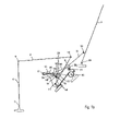
- FIGS. 7 a – 7 d show in a schematic overview five different phases during the forward-folding of the backrest of a motor vehicle seat according to a third embodiment of the present invention.
- FIGS. 8 a – 8 c show by way of comparison further possible embodiments with at least one guide member for guiding the seat part during the forward movement and lowering of the seat part.
- identical reference numerals refer to elements or groups of elements that are identical or have essentially the same function.
- FIG. 1 a shows in a schematic side view a motor vehicle seat according to a first embodiment of the present invention in a use position.
- the motor vehicle seat (hereinafter referred to in brief as “seat”), which is referenced 1 as a whole, is designed as shown in FIG. 1 a by way of example as a rear seat which is attached to the vehicle floor 8 via the schematically shown anchoring element 7 .
- the seat 1 comprises a seat part 2 with padding 20 and a backrest 3 with padding 21 .
- the backrest 3 is inclined backward at an acute angle and the seat part 2 with the padding 20 is inclined obliquely backward at an acute angle.
- the backrest 3 can be pivoted about the pivot axle 23 and folded forward.
- the seat part 2 is locked in the use position shown in FIG. 1 a and in the use position can thus not be pivoted forward and/or lowered.
- a locking element 16 designed as a lever is provided which in a known manner has a locking claw that engages in a locking catch fixed to the bodywork or in a locking bolt fixed to the bodywork.
- the locking lever 16 can be pivoted about the lower pivot axle 11 .
- the function of adjusting or regulating the angle of inclination of the backrest 3 is decoupled from the function of pivoting and lowering the seat part 2 , as will be explained in more detail below.
- the angle of inclination of the backrest 3 can be pivoted forward up to a predefined angle of inclination, as can be seen from FIG. 3 a .
- a locking mechanism may be provided. An example of such a locking mechanism is shown by way of example in FIG. 6 .
- a locking lever 31 which can pivot about the pivot axle 32 and on its lower edge has a comb-like structure in the form of a number of cut-outs 33 which are spaced apart from one another preferably equidistantly.
- one of the cut-outs 33 of the locking lever 31 engages in the known manner in a bolt or safety catch fixed to the bodywork.
- a rotary wheel or the like may be provided in order to pivot the backrest 3 about the pivot axle 23 ( FIG. 1 a ).
- the backrest 3 By releasing the locking mechanism, in particular by releasing the locking lever 31 shown in FIG. 6 , the backrest 3 is released and the backrest 3 can be folded toward the seat part. According to the invention, no cable pull or the like is actuated to unlock the seat part 2 when the locking mechanism of the backrest 3 is released.
- a pivot lever device which comprises a front adjustment lever 4 and a rear adjustment lever 9 .
- the front adjustment lever 4 can pivot about the lower pivot axle 5 of the anchoring element 7 fixed to the bodywork and is articulated to the seat part 2 in the region of the upper pivot axle 6 .
- the rear adjustment lever 9 can pivot about the lower pivot axle 11 fixed to the bodywork and is articulated to the seat part 2 in the region of the upper pivot axle 10 .
- the seat part 2 is designed as a rigid frame which connects the upper pivot axles 6 , 10 to one another.
- another front adjustment lever and another rear adjustment lever 9 may be provided in a comparable manner.
- a coupling lever 12 is provided, one end of which can pivot about the pivot axle 13 which is arranged on the side face 22 of the backrest 3 at a distance from the pivot axle 23 of the backrest 3 , and the other end of which is designed as a longitudinal hole 15 in order to couple the coupling lever 12 to the rear adjustment lever 9 via a rotary slide articulation.
- a pin 14 or a comparable protrusion which engages in the longitudinal hole 15 and is guided in the latter.
- the pin 14 or the protrusion is spaced apart from the lower pivot axle 11 of the rear adjustment lever 9 , in order to form a rotary slide articulation.
- the rear adjustment lever 9 is arranged between the locking lever 16 and the coupling lever 12 .
- a pin 18 Arranged at the front end of the coupling lever 12 is a pin 18 which projects inward toward the seat and in the use position shown in FIG. 1 a does not bear against the obliquely running bearing surface 25 of the locking lever 16 .
- a pin 17 Provided at the free end of the locking lever 16 is a pin 17 which projects outward away from the seat.
- a tension spring 19 is suspended in the pins 17 , 18 in order to couple the coupling lever 12 to the locking lever 16 and bias them with respect to one another.
- a gap is formed between the lower end of the longitudinal hole 15 and the pin 14 , said gap serving to compensate for manufacturing tolerances or serving as play during adjustment or regulation of the seat 1 .
- the pin 14 is located close to the lower end of the longitudinal hole 15 .
- FIG. 1 b a second embodiment of a motor vehicle seat according to the invention in the same position as in FIG. 1 a will be described.
- the elements that are mainly used for adjustment of the seat part, in particular the adjustment levers, are shown schematically as line connections in order to explain further details of an example of a locking mechanism for locking the seat part.
- identical reference numerals refer to identical elements, the description of which has been omitted below.
- the locking mechanism for locking the seat part 2 has a first locking lever 50 and a second lever 55 which can pivot about an axle 61 and 11 , respectively, said axles being fixed to the bodywork.
- a recess for receiving and locking the locking bolt 51 is provided at the rear end of the first locking lever 50 .
- the front actuating end 52 of the locking lever 50 bears against a shoulder 58 of the second lever 55 .
- the pin 18 is connected to the coupling lever 12 via a connecting element 56 , for example a carrier or a shoulder, and the pin 14 engaging in the longitudinal hole 15 is connected to the rear adjustment lever 9 via a corresponding connecting element 57 .
- the pin 18 is connected to the pin 17 via the spring 19 biased in the locking device, in order to couple the coupling lever to the second lever 55 .
- the pin 18 does not yet bear against the bearing surface 25 of the second lever 55 , said bearing surface lying opposite the shoulder 58 .
- the two levers 50 and 55 form a lock for locking the seat part 2 .
- the first and second embodiments are compared directly.
- the pin 18 coupled to the coupling lever 12 has come to bear against the bearing surface 25 of the second lever 55 and the pin 14 is located close to the center of the longitudinal hole 15 . In this position, the locking bolt is locked through the recess at the rear end of the locking lever 50 .
- the backrest 3 assumes the predefined angle of inclination. As shown in Fig 3 a , in this position the pin 14 does not yet bear against the upper end of the longitudinal hole 15 but rather a clearance or gap 24 is formed between the pin 14 and the upper end of the longitudinal hole 15 , which clearance or gap serves to compensate for manufacturing tolerances and the like.
- FIG. 3 b shows the motor vehicle seat according to the second embodiment in a position in which the locking bolt 51 is released.
- the pin 18 bearing against the bearing surface 25 , has pivoted the second lever 55 in the counter-clockwise direction to the extent that the actuating end 52 of the locking lever 50 has slid out over the shoulder 58 of the locking lever 50 and slid down the curved flank of the shoulder 58 .
- the locking lever 50 As the actuating end 52 slides down the curved flank of the shoulder 58 , the locking lever 50 , which is biased into the released position by the torsion spring 60 , is pivoted in the counter-clockwise direction, so that the recess at the rear end of the locking lever 50 finally releases the locking bolt 51 in order thus to unlock the seat part 2 . Because the flank of the shoulder 58 is curved concavely inward, this movement of the locking lever into the released position can take place very quickly. The position in which the locking bolt 51 is released, and the movement sequence, are precisely defined by the geometry of the shoulder 58 and of the actuating end 52 of the locking lever 50 .
- FIG. 4 a shows the motor vehicle seat in a intermediate position with the backrest 3 folded forward.
- the second lever 55 is pivoted further forward in the counter-clockwise direction and the seat part 2 thus starts, in addition to the pivoting movement, also to be lowered.
- the actuating end 52 remains on the lower end of the second lever 55 , so that the angular position of the locking lever 50 with the recess 54 for the locking bolt virtually does not change any more.
- the locking bolt is connected to the rear adjustment lever 9 via a connecting element 53 , so that according to the second embodiment there is no need for any locking bolt fixed to the bodywork.
- FIG. 5 a the position shown FIG. 5 a is assumed, in which the backrest 3 is folded onto the seat part 2 to the extent that an essentially horizontal loading area is formed.
- the front adjustment lever 4 is pivoted fully forward and bears against the vehicle floor 8 .
- the rear adjustment lever 9 is also pivoted fully forward and is essentially horizontal.
- the pin 14 still bears against the upper end of the longitudinal hole 15 .
- the locking lever 16 can be pivoted over a relatively large angular range, for example by about 90° or more, about the pivot axle 11 without engaging in a locking element or the like, for example in a locking bolt fixed to the bodywork.
- the above-described steps are carried out in reverse order, that is to say the backrest 3 is folded up in the clockwise direction until finally the locking lever 16 once again assumes the position shown in FIG. 2 , in which the seat part 2 is locked.
- the backrest 3 In the locked position of the seat part 2 , the backrest 3 can continue to be freely pivoted backward, until finally the angle of inclination of the backrest 3 is fixed by locking the backrest 3 , for example by means of the locking lever 31 shown in FIG. 6 .
- the locking lever 16 or 50 is automatically actuated by the coupling lever 12 without actuating any other elements, for example a cable pull known from the prior art.
- FIGS. 7 a to 7 d show a motor vehicle seat according to a third embodiment of the present invention in the movement phases shown in FIGS. 1 a – 4 a and 1 b – 4 b .
- the essential levers are shown schematically only as line connections in order to facilitate comprehension.
- the same reference numerals in this case refer to the same elements as described above with reference to FIGS. 1 to 6 , and hence the description thereof is omitted below.
- the coupling lever 12 is designed as a two-part lever which is connected to the backrest 3 and the rear adjustment lever 9 via the articulation axles 41 and 43 , respectively, and has a further articulation axle 42 at which the spring 19 is attached, for example via a pin or the like.
- the locking mechanism is designed in a manner comparable to that of the second embodiment and comprises a locking lever 50 and a second lever 55 .
- the arm 46 of the coupling lever 12 bears against the upper carrier 45 which is connected to the rear adjustment lever 9 .
- the carrier 45 can thus be used to guide the seat part 2 back as the backrest 3 is being folded back.
- the coupling lever 12 By folding the backrest 3 forward in the counter-clockwise direction, the coupling lever 12 is pushed down and the pin at the articulation axle 42 comes to bear against the bearing surface 25 of the second lever 55 . In the position shown in FIG. 7 b , the arm 46 of the coupling lever 12 is located approximately in the center between the lower carrier 44 and the upper carrier 45 of the rear adjustment lever 9 .
- the carrier 44 is carried by the arm 46 of the coupling lever 12 in order thus to pivot the rear adjustment lever 9 forward in the counter-clockwise direction and to lower the seat part 2 , as shown in FIG. 7 d.
- the locking element 40 according to the third embodiment may of course also be a locking bolt fixed to the bodywork which is pushed down by the tilting lever 12 or by an element coupled to the latter.
- a locking element according to the third embodiment may also be carried or released by a locking lever (not shown), for example in the manner described above with reference to FIGS. 1 to 5 b.
- FIGS. 8 a to 8 c show by way of comparison further possible embodiments comprising at least one guide member for guiding the seat part as the seat part is being moved forward and lowered.
- a curved guide member 80 is provided in which an element, for example a pin 85 , at the rear end of the seat part 2 engages.
- the guide member 80 is fixed to the bodywork, for example in a side part (not shown) which is fixedly attached to the vehicle.
- FIG. 8 a at the front end of the coupling lever 12 there is a longitudinal hole 15 in which a pin 14 engages in the manner described above, said pin being coupled to the seat part 2 .
- FIG. 8 b the front end of the coupling lever 12 is articulated directly on the seat part 2 .
- FIG. 8 c two curved guide members 81 and 82 are provided in which pins 85 and 86 connected to the seat part 2 engage in order to guide the movement of the seat part 2 as the backrest 3 is folded forward.
- guide members may be combined in a suitable manner with further adjustment mechanisms, for example pivot lever devices, in order to control in a suitable manner the movement sequence as the backrest is folded forward.
- guide members described as curved above may also be designed in some other way in order to suitably guide the movement of the seat part, for example in the form of guide members which run obliquely downward in an essentially rectilinear manner.
Landscapes
- Engineering & Computer Science (AREA)
- Aviation & Aerospace Engineering (AREA)
- Transportation (AREA)
- Mechanical Engineering (AREA)
- Seats For Vehicles (AREA)
Applications Claiming Priority (2)
| Application Number | Priority Date | Filing Date | Title |
|---|---|---|---|
| DE10355765.2 | 2003-11-26 | ||
| DE10355765A DE10355765A1 (de) | 2003-11-26 | 2003-11-26 | Kraftfahrzeugsitz |
Publications (2)
| Publication Number | Publication Date |
|---|---|
| US20050110323A1 US20050110323A1 (en) | 2005-05-26 |
| US7134725B2 true US7134725B2 (en) | 2006-11-14 |
Family
ID=34442344
Family Applications (1)
| Application Number | Title | Priority Date | Filing Date |
|---|---|---|---|
| US10/989,716 Expired - Lifetime US7134725B2 (en) | 2003-11-26 | 2004-11-15 | Motor vehicle seat |
Country Status (4)
| Country | Link |
|---|---|
| US (1) | US7134725B2 (enExample) |
| EP (1) | EP1535792B1 (enExample) |
| JP (1) | JP3971765B2 (enExample) |
| DE (2) | DE10355765A1 (enExample) |
Cited By (17)
| Publication number | Priority date | Publication date | Assignee | Title |
|---|---|---|---|---|
| US20060267366A1 (en) * | 2005-05-16 | 2006-11-30 | Johnson Controls Technology Company | 4-Bar freeplay cam |
| US20070063564A1 (en) * | 2004-02-17 | 2007-03-22 | Johnson Controls Gmbh | Vehicle seat, particularly for a motor vehicle, comprising a folding back rest and a foldable seat base and method |
| US20070063567A1 (en) * | 2005-09-20 | 2007-03-22 | Mazda Motor Corporation | Device for vehicle seat |
| US20080030060A1 (en) * | 2004-11-21 | 2008-02-07 | Bayerische Motoren Werke Ag | Vehicle Seat, in Particular Motor Vehicle Seat |
| US20080203772A1 (en) * | 2005-06-09 | 2008-08-28 | Holdampf Carl J | Mono Leg Transformer Seat |
| US20090322134A1 (en) * | 2006-07-31 | 2009-12-31 | Masayuki Yamada | Vehicular seat device |
| US20110006574A1 (en) * | 2008-03-20 | 2011-01-13 | Carroll Jeffrey P | Second row front tumble hook protection |
| US20110018326A1 (en) * | 2008-03-24 | 2011-01-27 | Ts Tech Co., Ltd. | Seat locking device and stowable vehicle seat |
| US20110037304A1 (en) * | 2009-08-12 | 2011-02-17 | Kaemmerer Joachim | Vehicle seat, in particular motor vehicle seat |
| US20150367761A1 (en) * | 2014-06-23 | 2015-12-24 | Kubota Corporation | Seat device for a vehicle |
| US9302600B2 (en) | 2011-06-23 | 2016-04-05 | Magna Seating Inc | Stow-in-floor seat assembly |
| US9944204B2 (en) * | 2016-01-07 | 2018-04-17 | Toyota Motor Engineering & Manufacturing North America, Inc. | Rear seat having two independent modes |
| US10336222B2 (en) | 2016-06-23 | 2019-07-02 | Magna Seating Inc | Stow-in-floor seat assembly with pitched easy entry position |
| US20190232830A1 (en) * | 2013-12-27 | 2019-08-01 | Ts Tech Co., Ltd. | Vehicle Seat |
| US10926673B2 (en) * | 2016-09-08 | 2021-02-23 | Adient Luxembourg Holding S.Á R.L. | Vehicle seat |
| US20250145059A1 (en) * | 2023-11-03 | 2025-05-08 | Atieva, Inc. | Stowing vehicle seat with break link mechanism |
| US12330841B2 (en) | 2022-03-18 | 2025-06-17 | 13872548 Canada, Inc. | Display case and method of assembly |
Families Citing this family (14)
| Publication number | Priority date | Publication date | Assignee | Title |
|---|---|---|---|---|
| DE102005023563A1 (de) * | 2005-05-18 | 2006-11-23 | Intier Automotive Seating Systems Gmbh | Fahrzeugsitz |
| DE102005029668A1 (de) * | 2005-06-22 | 2006-12-28 | Sitech Sitztechnik Gmbh | Verriegelung eines Kraftfahrzeugsitzes im Gelenkmechanismus (Lehne-Sitz) über einen Kniehebel |
| DE102006001013A1 (de) | 2006-01-05 | 2007-07-12 | Intier Automotive Seating Systems Gmbh | Kraftfahrzeugsitz mit einer Kopplung zwischen der Rückenlehnen- und der Sitzbewegung und Kraftfahrzeug mit einem solchen Kraftfahrzeugsitz |
| FR2899527B1 (fr) * | 2006-04-11 | 2008-06-20 | Faurecia Sieges Automobile | Agencement d'un siege de vehicule automobile pour en permettre le rangement dans un compartiment du plancher du dit vehicule, et vehicule adapte |
| WO2011002027A1 (ja) * | 2009-07-03 | 2011-01-06 | テイ・エス テック株式会社 | 乗物用シート |
| CN103052532B (zh) * | 2010-08-04 | 2016-01-20 | 约翰逊控股公司 | 用于车座的固定装置和车座 |
| WO2012093635A1 (ja) * | 2011-01-07 | 2012-07-12 | テイ・エス テック株式会社 | 格納式リアシート |
| KR101337935B1 (ko) | 2011-11-04 | 2013-12-09 | 포레시아오토모티브시팅코리아 유한회사 | 차량용 시트 장치 |
| DE102013221132B4 (de) * | 2013-10-17 | 2021-09-09 | Brose Fahrzeugteile SE & Co. Kommanditgesellschaft, Coburg | Fahrzeugsitz mit einem über ein Koppelelement mit einem Beschlaghebel gekoppelten Betätigungselement |
| JP6237465B2 (ja) | 2014-05-23 | 2017-11-29 | トヨタ紡織株式会社 | 乗物用シート |
| DE102016224625A1 (de) * | 2016-12-09 | 2018-06-14 | Brose Fahrzeugteile Gmbh & Co. Kg, Coburg | Fahrzeugsitz mit Sperrmechanimus zur Sperrung eines zumindest abschnittsweise absenkbaren Polsterträgers bei einer Verstellung einer Rückenlehne |
| DE102017218125A1 (de) * | 2017-10-11 | 2019-04-11 | Volkswagen Aktiengesellschaft | Fahrzeugsitz mit einem Easy-Entry-Mechanismus |
| US10442322B2 (en) | 2017-11-17 | 2019-10-15 | Brose Fahrzeugteile Gmbh & Co. Kommanditgesellschaft | Easy-entry vehicle seat |
| US10589642B2 (en) | 2017-11-15 | 2020-03-17 | Brose Fahrzeugteile Gmbh & Co. Kommanditgesellschaft, Coburg | Easy-entry vehicle seat |
Citations (23)
| Publication number | Priority date | Publication date | Assignee | Title |
|---|---|---|---|---|
| DE2011405A1 (de) | 1969-03-11 | 1970-10-01 | Hoogovens Delfstoffen N.V., Jjmuiden (Niederlande) | Vorrichtung zum Entfernen von achssymmetrischen Hohlkörpern aus ihnen zugeordneten Gegenkörpern, insbesondere von Protektoren aus Bohrrohren |
| US4597321A (en) | 1982-11-19 | 1986-07-01 | Gabelish Peter W | Rotary valve |
| US4869541A (en) * | 1988-12-27 | 1989-09-26 | Lear Siegler Seating Corporation | Forwardly pivotal seat assembly |
| US5527087A (en) * | 1993-10-28 | 1996-06-18 | Aisin Seiki Kabushiki Kaisha | Vehicle seat apparatus including a locking mechanism |
| US5536069A (en) * | 1993-10-12 | 1996-07-16 | Ford Motor Company | Rotary action switch assembly |
| US5570931A (en) * | 1995-09-29 | 1996-11-05 | Chrysler Corporation | Vehicle adjustable and stowable rear seat |
| DE19533932A1 (de) | 1995-09-13 | 1997-03-20 | Keiper Recaro Gmbh Co | Sitz, insbesondere Fondsitz für Kraftfahrzeuge |
| US5634686A (en) * | 1995-03-21 | 1997-06-03 | Aisin Seiki Kabushiki Kaisha | Seat device for vehicles |
| US5871255A (en) * | 1997-01-06 | 1999-02-16 | Chrysler Corporation | Vehicle seat |
| US6039401A (en) * | 1997-07-28 | 2000-03-21 | Lear Corporation | Self-latching and self-releasing latch mechanism for removable seat |
| US6123380A (en) * | 1999-06-11 | 2000-09-26 | Lear Corporation | Automotive seat assembly with folding structural supports for storage in a foot well for an automotive vehicle body |
| DE19932214A1 (de) | 1999-07-09 | 2001-01-11 | Lear Corp | Fahrzeugsitz |
| US6279982B1 (en) * | 1998-05-13 | 2001-08-28 | Toyota Jidosha Kabushiki Kaisha | Vehicle seat storing device |
| US6375255B1 (en) * | 1999-08-10 | 2002-04-23 | Toyota Jidosha Kabushiki Kaisha | Rear passenger seat in vehicle compartment |
| US6644730B2 (en) * | 2000-06-08 | 2003-11-11 | Takashimaya Nippatsu Kogyo Co., Ltd. | Storage type seat for automobile and seat storage structure |
| US20040056521A1 (en) * | 2002-09-19 | 2004-03-25 | Honda Giken Kogyo Kabushiki Kaisha | Seat arrangement structure for vehicle |
| US6773067B2 (en) * | 2002-08-08 | 2004-08-10 | Hyundai Motor Company | Reclining device for a rear seat of an automobile |
| US20040212237A1 (en) * | 2003-02-19 | 2004-10-28 | David Epaud | Fold-down seat and a vehicle including such a seat |
| US6827394B2 (en) * | 2001-10-16 | 2004-12-07 | Honda Giken Kogyo Kabushiki Kaisha | Vehicle seat system |
| US20050017532A1 (en) * | 2003-07-23 | 2005-01-27 | Honda Motor Co., Ltd. | Seat device for vehicle |
| US6971700B2 (en) * | 2003-07-03 | 2005-12-06 | Grupo Antolin-Ingenieria, S.A. | Motor vehicle seat |
| US7014263B2 (en) * | 2002-11-28 | 2006-03-21 | Araco Kabushiki Kaisha | Vehicle seats |
| US7021716B2 (en) * | 2001-07-06 | 2006-04-04 | Intier Automotive Inc. | Tip easy entry and fold flat recliner assembly |
Family Cites Families (9)
| Publication number | Priority date | Publication date | Assignee | Title |
|---|---|---|---|---|
| US4957321A (en) * | 1988-10-12 | 1990-09-18 | Ford Motor Company | Stowable vehicle seat with seat back position controller |
| CA2111725C (en) * | 1993-12-18 | 1998-10-13 | Wojciech Smuk | Combination reclining and folding mechanism for automotive seat assemblies |
| DE19616070C2 (de) * | 1996-04-23 | 1998-03-19 | Keiper Recaro Gmbh Co | Kraftfahrzeugsitz |
| DE19904009C1 (de) | 1999-02-02 | 2000-05-31 | Faure Bertrand Sitztech Gmbh | Kraftfahrzeug-Rücksitz mit klappbarer Rückenlehne und absenkbarem Sitzteil |
| JP3810944B2 (ja) * | 1999-05-21 | 2006-08-16 | 株式会社大井製作所 | シートバックのロック装置 |
| DE20114059U1 (de) * | 2001-08-25 | 2003-01-16 | Johnson Controls GmbH, 51399 Burscheid | Fahrzeugsitz |
| DE10228465A1 (de) * | 2002-06-26 | 2004-01-15 | Bayerische Motoren Werke Ag | Kraftfahrzeug |
| DE10236490B4 (de) * | 2002-08-09 | 2005-06-23 | Faurecia Autositze Gmbh & Co. Kg | Kraftfahrzeugsitz |
| DE10317238A1 (de) * | 2003-04-10 | 2004-10-28 | Brose Fahrzeugteile Gmbh & Co. Kommanditgesellschaft, Coburg | Kraftfahrzeugsitz |
-
2003
- 2003-11-26 DE DE10355765A patent/DE10355765A1/de not_active Withdrawn
-
2004
- 2004-11-15 US US10/989,716 patent/US7134725B2/en not_active Expired - Lifetime
- 2004-11-24 DE DE502004009078T patent/DE502004009078D1/de not_active Expired - Lifetime
- 2004-11-24 EP EP04106049A patent/EP1535792B1/de not_active Expired - Lifetime
- 2004-11-26 JP JP2004342543A patent/JP3971765B2/ja not_active Expired - Fee Related
Patent Citations (23)
| Publication number | Priority date | Publication date | Assignee | Title |
|---|---|---|---|---|
| DE2011405A1 (de) | 1969-03-11 | 1970-10-01 | Hoogovens Delfstoffen N.V., Jjmuiden (Niederlande) | Vorrichtung zum Entfernen von achssymmetrischen Hohlkörpern aus ihnen zugeordneten Gegenkörpern, insbesondere von Protektoren aus Bohrrohren |
| US4597321A (en) | 1982-11-19 | 1986-07-01 | Gabelish Peter W | Rotary valve |
| US4869541A (en) * | 1988-12-27 | 1989-09-26 | Lear Siegler Seating Corporation | Forwardly pivotal seat assembly |
| US5536069A (en) * | 1993-10-12 | 1996-07-16 | Ford Motor Company | Rotary action switch assembly |
| US5527087A (en) * | 1993-10-28 | 1996-06-18 | Aisin Seiki Kabushiki Kaisha | Vehicle seat apparatus including a locking mechanism |
| US5634686A (en) * | 1995-03-21 | 1997-06-03 | Aisin Seiki Kabushiki Kaisha | Seat device for vehicles |
| DE19533932A1 (de) | 1995-09-13 | 1997-03-20 | Keiper Recaro Gmbh Co | Sitz, insbesondere Fondsitz für Kraftfahrzeuge |
| US5570931A (en) * | 1995-09-29 | 1996-11-05 | Chrysler Corporation | Vehicle adjustable and stowable rear seat |
| US5871255A (en) * | 1997-01-06 | 1999-02-16 | Chrysler Corporation | Vehicle seat |
| US6039401A (en) * | 1997-07-28 | 2000-03-21 | Lear Corporation | Self-latching and self-releasing latch mechanism for removable seat |
| US6279982B1 (en) * | 1998-05-13 | 2001-08-28 | Toyota Jidosha Kabushiki Kaisha | Vehicle seat storing device |
| US6123380A (en) * | 1999-06-11 | 2000-09-26 | Lear Corporation | Automotive seat assembly with folding structural supports for storage in a foot well for an automotive vehicle body |
| DE19932214A1 (de) | 1999-07-09 | 2001-01-11 | Lear Corp | Fahrzeugsitz |
| US6375255B1 (en) * | 1999-08-10 | 2002-04-23 | Toyota Jidosha Kabushiki Kaisha | Rear passenger seat in vehicle compartment |
| US6644730B2 (en) * | 2000-06-08 | 2003-11-11 | Takashimaya Nippatsu Kogyo Co., Ltd. | Storage type seat for automobile and seat storage structure |
| US7021716B2 (en) * | 2001-07-06 | 2006-04-04 | Intier Automotive Inc. | Tip easy entry and fold flat recliner assembly |
| US6827394B2 (en) * | 2001-10-16 | 2004-12-07 | Honda Giken Kogyo Kabushiki Kaisha | Vehicle seat system |
| US6773067B2 (en) * | 2002-08-08 | 2004-08-10 | Hyundai Motor Company | Reclining device for a rear seat of an automobile |
| US20040056521A1 (en) * | 2002-09-19 | 2004-03-25 | Honda Giken Kogyo Kabushiki Kaisha | Seat arrangement structure for vehicle |
| US7014263B2 (en) * | 2002-11-28 | 2006-03-21 | Araco Kabushiki Kaisha | Vehicle seats |
| US20040212237A1 (en) * | 2003-02-19 | 2004-10-28 | David Epaud | Fold-down seat and a vehicle including such a seat |
| US6971700B2 (en) * | 2003-07-03 | 2005-12-06 | Grupo Antolin-Ingenieria, S.A. | Motor vehicle seat |
| US20050017532A1 (en) * | 2003-07-23 | 2005-01-27 | Honda Motor Co., Ltd. | Seat device for vehicle |
Cited By (29)
| Publication number | Priority date | Publication date | Assignee | Title |
|---|---|---|---|---|
| US20070063564A1 (en) * | 2004-02-17 | 2007-03-22 | Johnson Controls Gmbh | Vehicle seat, particularly for a motor vehicle, comprising a folding back rest and a foldable seat base and method |
| US7413251B2 (en) * | 2004-02-17 | 2008-08-19 | Johnson Controls Gmbh | Vehicle seat, particularly for a motor vehicle, comprising a folding back rest and a foldable seat base and method |
| US20080030060A1 (en) * | 2004-11-21 | 2008-02-07 | Bayerische Motoren Werke Ag | Vehicle Seat, in Particular Motor Vehicle Seat |
| US7651166B2 (en) * | 2004-11-21 | 2010-01-26 | Bayerische Motoren Werke Aktiengesellschaft | Vehicle seat, in particular motor vehicle seat |
| US20060267366A1 (en) * | 2005-05-16 | 2006-11-30 | Johnson Controls Technology Company | 4-Bar freeplay cam |
| US20080203772A1 (en) * | 2005-06-09 | 2008-08-28 | Holdampf Carl J | Mono Leg Transformer Seat |
| US7850220B2 (en) * | 2005-06-09 | 2010-12-14 | Intier Automotive Inc. | Mono leg transformer seat |
| US20070063567A1 (en) * | 2005-09-20 | 2007-03-22 | Mazda Motor Corporation | Device for vehicle seat |
| US7661760B2 (en) * | 2005-09-20 | 2010-02-16 | Mazda Motor Corporation | Device for vehicle seat |
| US8152240B2 (en) * | 2006-07-31 | 2012-04-10 | Toyota Jidosha Kabushiki Kaisha | Vehicular seat device |
| US20090322134A1 (en) * | 2006-07-31 | 2009-12-31 | Masayuki Yamada | Vehicular seat device |
| US8251450B2 (en) * | 2008-03-20 | 2012-08-28 | Intier Automotive Inc | Second row front tumble hook protection |
| US20110006574A1 (en) * | 2008-03-20 | 2011-01-13 | Carroll Jeffrey P | Second row front tumble hook protection |
| US20110018326A1 (en) * | 2008-03-24 | 2011-01-27 | Ts Tech Co., Ltd. | Seat locking device and stowable vehicle seat |
| US8287024B2 (en) * | 2008-03-24 | 2012-10-16 | Ts Tech Co., Ltd. | Seat locking device and stowable vehicle seat |
| US8474910B2 (en) | 2009-08-12 | 2013-07-02 | Keiper Gmbh & Co. Kg | Vehicle seat, in particular motor vehicle seat |
| US20110037304A1 (en) * | 2009-08-12 | 2011-02-17 | Kaemmerer Joachim | Vehicle seat, in particular motor vehicle seat |
| US9302600B2 (en) | 2011-06-23 | 2016-04-05 | Magna Seating Inc | Stow-in-floor seat assembly |
| US20190232830A1 (en) * | 2013-12-27 | 2019-08-01 | Ts Tech Co., Ltd. | Vehicle Seat |
| US20150367761A1 (en) * | 2014-06-23 | 2015-12-24 | Kubota Corporation | Seat device for a vehicle |
| US9725018B2 (en) * | 2014-06-23 | 2017-08-08 | Kubota Corporation | Seat device for a vehicle |
| US9944204B2 (en) * | 2016-01-07 | 2018-04-17 | Toyota Motor Engineering & Manufacturing North America, Inc. | Rear seat having two independent modes |
| US10336222B2 (en) | 2016-06-23 | 2019-07-02 | Magna Seating Inc | Stow-in-floor seat assembly with pitched easy entry position |
| US20190337426A1 (en) * | 2016-06-23 | 2019-11-07 | Magna Seating Inc | Stow-in-floor seat assembly with pitched easy entry position |
| US10675998B2 (en) * | 2016-06-23 | 2020-06-09 | Magna Seating Inc. | Stow-in-floor seat assembly with pitched easy entry position |
| US10926673B2 (en) * | 2016-09-08 | 2021-02-23 | Adient Luxembourg Holding S.Á R.L. | Vehicle seat |
| US12330841B2 (en) | 2022-03-18 | 2025-06-17 | 13872548 Canada, Inc. | Display case and method of assembly |
| US20250145059A1 (en) * | 2023-11-03 | 2025-05-08 | Atieva, Inc. | Stowing vehicle seat with break link mechanism |
| US12583369B2 (en) * | 2023-11-03 | 2026-03-24 | Atieva, Inc. | Stowing vehicle seat with break link mechanism |
Also Published As
| Publication number | Publication date |
|---|---|
| EP1535792B1 (de) | 2009-03-04 |
| DE502004009078D1 (de) | 2009-04-16 |
| JP2005153874A (ja) | 2005-06-16 |
| DE10355765A1 (de) | 2005-06-30 |
| US20050110323A1 (en) | 2005-05-26 |
| EP1535792A3 (de) | 2007-06-27 |
| JP3971765B2 (ja) | 2007-09-05 |
| EP1535792A2 (de) | 2005-06-01 |
Similar Documents
| Publication | Publication Date | Title |
|---|---|---|
| US7134725B2 (en) | Motor vehicle seat | |
| US7137666B2 (en) | Vehicle seat with a pivotable backrest | |
| KR101679184B1 (ko) | 차량 시트, 특히 자동차 시트 | |
| US7240950B2 (en) | Seat that is retractable into the floor | |
| CA2289839C (en) | Slide/fold/ez entry seat mechanism | |
| US6695405B2 (en) | Seat device including a fold-down back | |
| US6631952B1 (en) | Automobile seat | |
| US7300109B2 (en) | Seat assembly for a motor vehicle seat | |
| JP3336262B2 (ja) | 車両座席用のヒンジ装置及びそのような装置を含む車両座席 | |
| EP2055524B1 (en) | Seat apparatus for vehicle | |
| US6805410B2 (en) | Fitting for a vehicle seat | |
| US6817669B2 (en) | Vehicle seat having a floor position | |
| US5466048A (en) | Backrest release mechanism | |
| KR100984461B1 (ko) | 플로어 격납 자동 시트 조립체 | |
| US20020125757A1 (en) | Vehicle seat provided with a fold-down back | |
| US12606060B2 (en) | Vehicle seat with a locking element | |
| US20040051361A1 (en) | Motor vehicle seat | |
| CN104039590B (zh) | 锁定和斜度调整组件 | |
| US20040075324A1 (en) | Motor vehicle seat | |
| US7017994B2 (en) | Motor vehicle seat | |
| US20060261658A1 (en) | Motor vehicle seat | |
| CN109996699A (zh) | 车辆座椅,尤其是机动车辆座椅 | |
| US7578555B2 (en) | Motor vehicle seat | |
| JPH01226448A (ja) | 折畳シート | |
| CN101018690A (zh) | 可收起的座椅 |
Legal Events
| Date | Code | Title | Description |
|---|---|---|---|
| AS | Assignment |
Owner name: BROSE FAHRZEUGTEILE GMBH & CO. KG COBURG, GERMANY Free format text: ASSIGNMENT OF ASSIGNORS INTEREST;ASSIGNORS:HOLMANN, JOCHEN;GOBEL, OLAF;REEL/FRAME:015468/0960 Effective date: 20041104 |
|
| STCF | Information on status: patent grant |
Free format text: PATENTED CASE |
|
| FPAY | Fee payment |
Year of fee payment: 4 |
|
| FPAY | Fee payment |
Year of fee payment: 8 |
|
| MAFP | Maintenance fee payment |
Free format text: PAYMENT OF MAINTENANCE FEE, 12TH YEAR, LARGE ENTITY (ORIGINAL EVENT CODE: M1553) Year of fee payment: 12 |
|
| AS | Assignment |
Owner name: BROSE FAHRZEUGTEILE SE & CO. KG (COBURG), GERMANY Free format text: CHANGE OF NAME;ASSIGNOR:BROSE FAHRZEUGTEILE GMBH & CO. KG, COBURG;REEL/FRAME:053902/0710 Effective date: 20200226 |