EP1533533A1 - Doppelreihiges kugellager zur abstützung einer scheibe - Google Patents
Doppelreihiges kugellager zur abstützung einer scheibe Download PDFInfo
- Publication number
- EP1533533A1 EP1533533A1 EP03760924A EP03760924A EP1533533A1 EP 1533533 A1 EP1533533 A1 EP 1533533A1 EP 03760924 A EP03760924 A EP 03760924A EP 03760924 A EP03760924 A EP 03760924A EP 1533533 A1 EP1533533 A1 EP 1533533A1
- Authority
- EP
- European Patent Office
- Prior art keywords
- balls
- ring
- outer ring
- diameter
- circumferential surface
- Prior art date
- Legal status (The legal status is an assumption and is not a legal conclusion. Google has not performed a legal analysis and makes no representation as to the accuracy of the status listed.)
- Withdrawn
Links
- 238000005096 rolling process Methods 0.000 claims abstract description 54
- 230000004323 axial length Effects 0.000 claims description 11
- 238000013459 approach Methods 0.000 claims description 3
- 239000000463 material Substances 0.000 claims description 2
- 239000007769 metal material Substances 0.000 claims 1
- 239000004519 grease Substances 0.000 abstract description 51
- 238000005461 lubrication Methods 0.000 abstract description 7
- 238000010276 construction Methods 0.000 abstract 2
- 230000006835 compression Effects 0.000 description 9
- 238000007906 compression Methods 0.000 description 9
- 239000003507 refrigerant Substances 0.000 description 7
- 238000006073 displacement reaction Methods 0.000 description 6
- 230000003068 static effect Effects 0.000 description 6
- 229910000838 Al alloy Inorganic materials 0.000 description 5
- 229920003002 synthetic resin Polymers 0.000 description 5
- 239000000057 synthetic resin Substances 0.000 description 5
- 238000004378 air conditioning Methods 0.000 description 4
- 229910000831 Steel Inorganic materials 0.000 description 3
- 238000005192 partition Methods 0.000 description 3
- 230000001105 regulatory effect Effects 0.000 description 3
- 239000010959 steel Substances 0.000 description 3
- 235000014676 Phragmites communis Nutrition 0.000 description 2
- 230000005540 biological transmission Effects 0.000 description 2
- 230000008859 change Effects 0.000 description 2
- 238000001816 cooling Methods 0.000 description 2
- 238000004519 manufacturing process Methods 0.000 description 2
- 230000007246 mechanism Effects 0.000 description 2
- 229910052751 metal Inorganic materials 0.000 description 2
- 239000002184 metal Substances 0.000 description 2
- 239000008186 active pharmaceutical agent Substances 0.000 description 1
- 230000015556 catabolic process Effects 0.000 description 1
- 239000000919 ceramic Substances 0.000 description 1
- 238000006731 degradation reaction Methods 0.000 description 1
- 238000007791 dehumidification Methods 0.000 description 1
- 230000002349 favourable effect Effects 0.000 description 1
- 238000005429 filling process Methods 0.000 description 1
- 239000000446 fuel Substances 0.000 description 1
- 230000006872 improvement Effects 0.000 description 1
- 238000002347 injection Methods 0.000 description 1
- 239000007924 injection Substances 0.000 description 1
- 238000005304 joining Methods 0.000 description 1
- 230000001050 lubricating effect Effects 0.000 description 1
- 239000000696 magnetic material Substances 0.000 description 1
- 230000000149 penetrating effect Effects 0.000 description 1
- 230000004044 response Effects 0.000 description 1
- 238000004904 shortening Methods 0.000 description 1
- 238000000638 solvent extraction Methods 0.000 description 1
Images




Classifications
-
- F—MECHANICAL ENGINEERING; LIGHTING; HEATING; WEAPONS; BLASTING
- F16—ENGINEERING ELEMENTS AND UNITS; GENERAL MEASURES FOR PRODUCING AND MAINTAINING EFFECTIVE FUNCTIONING OF MACHINES OR INSTALLATIONS; THERMAL INSULATION IN GENERAL
- F16C—SHAFTS; FLEXIBLE SHAFTS; ELEMENTS OR CRANKSHAFT MECHANISMS; ROTARY BODIES OTHER THAN GEARING ELEMENTS; BEARINGS
- F16C19/00—Bearings with rolling contact, for exclusively rotary movement
- F16C19/02—Bearings with rolling contact, for exclusively rotary movement with bearing balls essentially of the same size in one or more circular rows
- F16C19/04—Bearings with rolling contact, for exclusively rotary movement with bearing balls essentially of the same size in one or more circular rows for radial load mainly
- F16C19/08—Bearings with rolling contact, for exclusively rotary movement with bearing balls essentially of the same size in one or more circular rows for radial load mainly with two or more rows of balls
-
- F—MECHANICAL ENGINEERING; LIGHTING; HEATING; WEAPONS; BLASTING
- F16—ENGINEERING ELEMENTS AND UNITS; GENERAL MEASURES FOR PRODUCING AND MAINTAINING EFFECTIVE FUNCTIONING OF MACHINES OR INSTALLATIONS; THERMAL INSULATION IN GENERAL
- F16C—SHAFTS; FLEXIBLE SHAFTS; ELEMENTS OR CRANKSHAFT MECHANISMS; ROTARY BODIES OTHER THAN GEARING ELEMENTS; BEARINGS
- F16C33/00—Parts of bearings; Special methods for making bearings or parts thereof
- F16C33/30—Parts of ball or roller bearings
- F16C33/58—Raceways; Race rings
-
- F—MECHANICAL ENGINEERING; LIGHTING; HEATING; WEAPONS; BLASTING
- F04—POSITIVE - DISPLACEMENT MACHINES FOR LIQUIDS; PUMPS FOR LIQUIDS OR ELASTIC FLUIDS
- F04B—POSITIVE-DISPLACEMENT MACHINES FOR LIQUIDS; PUMPS
- F04B27/00—Multi-cylinder pumps specially adapted for elastic fluids and characterised by number or arrangement of cylinders
- F04B27/08—Multi-cylinder pumps specially adapted for elastic fluids and characterised by number or arrangement of cylinders having cylinders coaxial with, or parallel or inclined to, main shaft axis
- F04B27/0873—Component parts, e.g. sealings; Manufacturing or assembly thereof
- F04B27/0895—Component parts, e.g. sealings; Manufacturing or assembly thereof driving means
-
- F—MECHANICAL ENGINEERING; LIGHTING; HEATING; WEAPONS; BLASTING
- F04—POSITIVE - DISPLACEMENT MACHINES FOR LIQUIDS; PUMPS FOR LIQUIDS OR ELASTIC FLUIDS
- F04B—POSITIVE-DISPLACEMENT MACHINES FOR LIQUIDS; PUMPS
- F04B27/00—Multi-cylinder pumps specially adapted for elastic fluids and characterised by number or arrangement of cylinders
- F04B27/08—Multi-cylinder pumps specially adapted for elastic fluids and characterised by number or arrangement of cylinders having cylinders coaxial with, or parallel or inclined to, main shaft axis
- F04B27/10—Multi-cylinder pumps specially adapted for elastic fluids and characterised by number or arrangement of cylinders having cylinders coaxial with, or parallel or inclined to, main shaft axis having stationary cylinders
- F04B27/1036—Component parts, details, e.g. sealings, lubrication
- F04B27/1054—Actuating elements
- F04B27/1063—Actuating-element bearing means or driving-axis bearing means
-
- F—MECHANICAL ENGINEERING; LIGHTING; HEATING; WEAPONS; BLASTING
- F16—ENGINEERING ELEMENTS AND UNITS; GENERAL MEASURES FOR PRODUCING AND MAINTAINING EFFECTIVE FUNCTIONING OF MACHINES OR INSTALLATIONS; THERMAL INSULATION IN GENERAL
- F16C—SHAFTS; FLEXIBLE SHAFTS; ELEMENTS OR CRANKSHAFT MECHANISMS; ROTARY BODIES OTHER THAN GEARING ELEMENTS; BEARINGS
- F16C13/00—Rolls, drums, discs, or the like; Bearings or mountings therefor
- F16C13/02—Bearings
-
- F—MECHANICAL ENGINEERING; LIGHTING; HEATING; WEAPONS; BLASTING
- F16—ENGINEERING ELEMENTS AND UNITS; GENERAL MEASURES FOR PRODUCING AND MAINTAINING EFFECTIVE FUNCTIONING OF MACHINES OR INSTALLATIONS; THERMAL INSULATION IN GENERAL
- F16C—SHAFTS; FLEXIBLE SHAFTS; ELEMENTS OR CRANKSHAFT MECHANISMS; ROTARY BODIES OTHER THAN GEARING ELEMENTS; BEARINGS
- F16C19/00—Bearings with rolling contact, for exclusively rotary movement
- F16C19/02—Bearings with rolling contact, for exclusively rotary movement with bearing balls essentially of the same size in one or more circular rows
- F16C19/14—Bearings with rolling contact, for exclusively rotary movement with bearing balls essentially of the same size in one or more circular rows for both radial and axial load
- F16C19/18—Bearings with rolling contact, for exclusively rotary movement with bearing balls essentially of the same size in one or more circular rows for both radial and axial load with two or more rows of balls
- F16C19/181—Bearings with rolling contact, for exclusively rotary movement with bearing balls essentially of the same size in one or more circular rows for both radial and axial load with two or more rows of balls with angular contact
- F16C19/183—Bearings with rolling contact, for exclusively rotary movement with bearing balls essentially of the same size in one or more circular rows for both radial and axial load with two or more rows of balls with angular contact with two rows at opposite angles
- F16C19/184—Bearings with rolling contact, for exclusively rotary movement with bearing balls essentially of the same size in one or more circular rows for both radial and axial load with two or more rows of balls with angular contact with two rows at opposite angles in O-arrangement
-
- F—MECHANICAL ENGINEERING; LIGHTING; HEATING; WEAPONS; BLASTING
- F16—ENGINEERING ELEMENTS AND UNITS; GENERAL MEASURES FOR PRODUCING AND MAINTAINING EFFECTIVE FUNCTIONING OF MACHINES OR INSTALLATIONS; THERMAL INSULATION IN GENERAL
- F16C—SHAFTS; FLEXIBLE SHAFTS; ELEMENTS OR CRANKSHAFT MECHANISMS; ROTARY BODIES OTHER THAN GEARING ELEMENTS; BEARINGS
- F16C33/00—Parts of bearings; Special methods for making bearings or parts thereof
- F16C33/30—Parts of ball or roller bearings
- F16C33/32—Balls
-
- F—MECHANICAL ENGINEERING; LIGHTING; HEATING; WEAPONS; BLASTING
- F16—ENGINEERING ELEMENTS AND UNITS; GENERAL MEASURES FOR PRODUCING AND MAINTAINING EFFECTIVE FUNCTIONING OF MACHINES OR INSTALLATIONS; THERMAL INSULATION IN GENERAL
- F16C—SHAFTS; FLEXIBLE SHAFTS; ELEMENTS OR CRANKSHAFT MECHANISMS; ROTARY BODIES OTHER THAN GEARING ELEMENTS; BEARINGS
- F16C33/00—Parts of bearings; Special methods for making bearings or parts thereof
- F16C33/30—Parts of ball or roller bearings
- F16C33/38—Ball cages
- F16C33/41—Ball cages comb-shaped
- F16C33/412—Massive or moulded comb cages, e.g. snap ball cages
- F16C33/414—Massive or moulded comb cages, e.g. snap ball cages formed as one-piece cages, i.e. monoblock comb cages
-
- F—MECHANICAL ENGINEERING; LIGHTING; HEATING; WEAPONS; BLASTING
- F16—ENGINEERING ELEMENTS AND UNITS; GENERAL MEASURES FOR PRODUCING AND MAINTAINING EFFECTIVE FUNCTIONING OF MACHINES OR INSTALLATIONS; THERMAL INSULATION IN GENERAL
- F16C—SHAFTS; FLEXIBLE SHAFTS; ELEMENTS OR CRANKSHAFT MECHANISMS; ROTARY BODIES OTHER THAN GEARING ELEMENTS; BEARINGS
- F16C33/00—Parts of bearings; Special methods for making bearings or parts thereof
- F16C33/30—Parts of ball or roller bearings
- F16C33/66—Special parts or details in view of lubrication
- F16C33/6603—Special parts or details in view of lubrication with grease as lubricant
- F16C33/6629—Details of distribution or circulation inside the bearing, e.g. grooves on the cage or passages in the rolling elements
-
- F—MECHANICAL ENGINEERING; LIGHTING; HEATING; WEAPONS; BLASTING
- F16—ENGINEERING ELEMENTS AND UNITS; GENERAL MEASURES FOR PRODUCING AND MAINTAINING EFFECTIVE FUNCTIONING OF MACHINES OR INSTALLATIONS; THERMAL INSULATION IN GENERAL
- F16C—SHAFTS; FLEXIBLE SHAFTS; ELEMENTS OR CRANKSHAFT MECHANISMS; ROTARY BODIES OTHER THAN GEARING ELEMENTS; BEARINGS
- F16C33/00—Parts of bearings; Special methods for making bearings or parts thereof
- F16C33/72—Sealings
- F16C33/76—Sealings of ball or roller bearings
- F16C33/78—Sealings of ball or roller bearings with a diaphragm, disc, or ring, with or without resilient members
- F16C33/784—Sealings of ball or roller bearings with a diaphragm, disc, or ring, with or without resilient members mounted to a groove in the inner surface of the outer race and extending toward the inner race
- F16C33/7843—Sealings of ball or roller bearings with a diaphragm, disc, or ring, with or without resilient members mounted to a groove in the inner surface of the outer race and extending toward the inner race with a single annular sealing disc
- F16C33/7853—Sealings of ball or roller bearings with a diaphragm, disc, or ring, with or without resilient members mounted to a groove in the inner surface of the outer race and extending toward the inner race with a single annular sealing disc with one or more sealing lips to contact the inner race
-
- F—MECHANICAL ENGINEERING; LIGHTING; HEATING; WEAPONS; BLASTING
- F16—ENGINEERING ELEMENTS AND UNITS; GENERAL MEASURES FOR PRODUCING AND MAINTAINING EFFECTIVE FUNCTIONING OF MACHINES OR INSTALLATIONS; THERMAL INSULATION IN GENERAL
- F16C—SHAFTS; FLEXIBLE SHAFTS; ELEMENTS OR CRANKSHAFT MECHANISMS; ROTARY BODIES OTHER THAN GEARING ELEMENTS; BEARINGS
- F16C2240/00—Specified values or numerical ranges of parameters; Relations between them
- F16C2240/40—Linear dimensions, e.g. length, radius, thickness, gap
-
- F—MECHANICAL ENGINEERING; LIGHTING; HEATING; WEAPONS; BLASTING
- F16—ENGINEERING ELEMENTS AND UNITS; GENERAL MEASURES FOR PRODUCING AND MAINTAINING EFFECTIVE FUNCTIONING OF MACHINES OR INSTALLATIONS; THERMAL INSULATION IN GENERAL
- F16C—SHAFTS; FLEXIBLE SHAFTS; ELEMENTS OR CRANKSHAFT MECHANISMS; ROTARY BODIES OTHER THAN GEARING ELEMENTS; BEARINGS
- F16C2361/00—Apparatus or articles in engineering in general
- F16C2361/63—Gears with belts and pulleys
Definitions
- the pulley support double row ball bearing according to the present invention is built into automotive auxiliary equipment such as a compressor constituting an automotive interior air conditioning apparatus, and is used for rotatably supporting a pulley for rotationally driving the automotive auxiliary equipment with respect to a fixed support member such as a housing.
- Japanese Unexamined Patent Publication No. H 11-280644 discloses a swash-plate type compressor which converts rotational motion of a rotation shaft into reciprocating motion of a piston using a swash-plate, and performs compression of refrigerant by this piston.
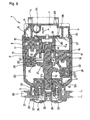
- FIG 9 and FIG 10 illustrate one example of such a conventionally known swash-plate type compressor.
- a casing 2, constituting a compressor 1 is formed by sandwiching a central main body 3 between a head case 4 and a swash-plate case 5 from both sides in the axial direction (left-right direction in FIG. 9), and then joining these with a plurality of fastening bolts (not shown).
- the low pressure chamber 6, which is shown in FIG. 9 as if divided into a plurality of sections, has the sections communicating with each other and connected to a single inlet port 9 (FIG. 10) provided on the outside surface of the head case 4.
- the high pressure chamber 7 is connected to an outlet port (not shown) also provided on the head case 4.
- the inlet port 9 is connected to the outlet of an evaporator (not shown) constituting this vapor compression type refrigerator, and the outlet port is connected to the inlet of a condenser (not shown) constituting this vapor compression type refrigerator.
- a rotation shaft 10 in a state of spanning between the main body 3 and the swash-plate case 5, is freely supported for rotation alone. That is to say, both ends of the rotation shaft 10 are supported by a pair of radial needle bearings 11a and 11b, on the main body 3 and the swash-plate case 5, and the thrust load exerted on this rotation shaft 10 is freely supported by a pair of thrust needle bearings 12a and 12b.
- a pair of thrust needle bearings 12a and 12b one (right hand side in FIG 9) thrust needle bearing 12a is provided between a part of the main body 3 and a step portion 13 formed on one end (right end in FIG 9) of the rotation shaft 10, via a disc spring 14.
- the other thrust needle bearing 12b is provided between a thrust plate 15 externally fitted to the outer circumferential surface of an intermediate part of the rotation shaft 10 and the swash-plate case 5.
- a plurality for example in the example shown on the figure, there are six evenly spaced in the circumferential direction
- a sliding portion 18 provided at the tip half portion (right half of FIG 9) of the respective pistons 17 is fitted to allow free displacement in the axial direction.
- the space between the bottom face of the cylindrical bore 16 and the tip end surface of the piston 17 (right end surface in FIG 9) serves as a compression chamber 19.
- a swash-plate 21 is fixed with a predetermined inclination angle with respect to the rotation shaft 10 such that this swash-plate rotates together with the rotation shaft 10.
- a plurality of locations in the circumferential direction of the swash-plate 21 and each of the pistons 17 are individually linked by means of a pair each of sliding shoes 22.
- each of the connecting portions 23 by means of a guide surface (not shown in the figure), is allowed free displacement only in the axial direction (left-right direction in FIG. 9) of the piston 17. Therefore, each of the pistons 17 is also fitted within the cylindrical bore 16 in such a way as to allow displacement only in the axial direction (rotation is not possible).
- each of the connecting portions 23 pushes and pulls each of the pistons 17 in the axial direction in accordance with the oscillating reciprocal displacement of the swash-plate 21 due to the rotation of the rotation shaft 10, and reciprocates each of the sliding portions 18 within the cylindrical bore 16 in the axial direction.
- the partition plate 8 which is sandwiched at the contact portion between the main body 3 and the head case 4, for partitioning the low pressure chamber 6, the high pressure chamber 7 and each of the cylindrical bores 16, is formed penetrating in the axial direction, an inlet 25 for communicating between the low pressure chamber and each cylindrical bore 16, and an outlet for communicating between the high pressure chamber 7 and each cylindrical bore 16. Also, in the part of each of the cylindrical bores 16 which faces one end of each of the inlets 25, is provided a reed valve type inlet valve 27, which allows only flow of refrigerant vapor from the low pressure chamber 6 to each of the cylindrical bores 16.
- a reed valve type outlet valve 28 which allows only flow of refrigerant vapor from the cylindrical bore 16 to the high pressure chamber 7.
- a stopper 29, which restricts displacement in the direction away from each of the outlet valve 26, is attached.
- the rotation shaft 10 of the compressor 1 constructed in the above manner is driven by the propulsion engine of an automobile. Therefore, in the case of the example shown in the figure, on the periphery of a support member, in other words a support cylinder 30, provided at the center of the outside surface (left side surface in FIG. 9) of the swash-plate case 5 constituting the casing 2, is rotationally supported a driven pulley 31, by means of a double-row bearing.
- This driven pulley 31 is constructed in an overall annular form with a C-shaped cross section, and a solenoid 33, which is fixed to the outside surface of the swash-plate case 5, is provided within an internal cavity of the driven pulley 31.
- a mounting bracket 34 At an end portion of the rotation shaft, which protrudes from the support cylinder 30, is fixed a mounting bracket 34, and around the circumferential surface of this mounting bracket 34, is supported an annular plate of magnetic material, via a plate spring 36.
- This annular plate 35 when there is no current through the solenoid 33, is separated from the driven pulley 31 due to the elasticity of the plate spring 36, as shown in FIG 9. However, when there is a current through the solenoid 33, it is attracted towards this driven pulley 31, and hence allows the transmission of torque from this driven pulley 31 to the rotation shaft 10.
- the solenoid 33, the annular plate 35 and the plate spring 36 constitute an electromagnetic clutch 37 for connecting and disconnecting the driven pulley 31 and the rotation shaft 10. Also, between the driving pulley fixed to the end of the crank shaft of the propulsion engine and the driven pulley 31, is spanned an endless belt 38. Furthermore, in a state where the driven pulley 31 and the rotation shaft 10 are connected by the electromagnetic clutch 37, the rotation shaft 10 is rotated based on the rotation of the endless belt 38.
- the operation of the swash-plate type compressor 1 formed in the above manner is as follows. That is to say, in order to perform cooling and dehumidification of the automobile interior, in the case of operating a vapor compression type refrigerator, the rotation shaft 10 is rotated by the propulsion engine, being the driving source. As a result, the swash-plate 21 rotates, and the sliding portions 18 constituting the multiple pistons 17 reciprocate within the respective cylindrical bores 16. Furthermore, in accordance with such reciprocation of the sliding portions 18, the refrigerant vapor sucked in from the inlet port 9 is sucked from the low pressure chamber 6 through each inlet 25 into the compression chambers 19. This refrigerant vapor, after being compressed inside each of the compression chambers 19, is sent out to the high pressure chamber 7 via the outlets 26, and discharged from the outlet port.
- the compressor shown in FIG 9 is one in which the inclination angle of the swash-plate with respect to the rotation shaft is unchangeable, and hence the refrigerant discharge volume is fixed.
- a variable displacement swash-plate type compressor in which the inclination angle of the swash-plate with respect to the rotation shaft can be changed in order to change the discharge volume in accordance with cooling load and the like, is conventionally widely known from, for example, the disclosure of Japanese Unexamined Patent Publication No. H 8-326655 and so on, and is commonly implemented.
- a compressor for a vapor compression type refrigerator constituting an automobile air conditioning apparatus the use of a scroll type compressor is also being researched in some places.
- a conventional compressor in which a piston is reciprocated by means of a ball joint, this is still also being used in some places.
- the compressor constituting the automobile air conditioning apparatus is driven by the endless belt spanning between the driving pulley fixed to the end of the crank shaft of the propulsion engine and the driven pulley provided on the compressor side. Therefore, a radial load based on the tension force of the endless belt, is exerted on the bearing which rotatably supports the driven pulley.
- the tension force on the endless belt in other words, the radial load, becomes correspondingly large. Therefore, as a bearing for supporting the driven pulley, in order to support this large radial load, it is necessary to use one with sufficient load capacity.
- the pulley support double row ball bearing of the present invention was invented in consideration of such circumstances.
- the present inventor first thought of ensuring the required rigidity by reducing the diameter of the balls and reducing the spacing between the balls arranged in double rows, as well as supporting the driven pulley using a double row ball bearing with reduced dimensions related to the axial direction (Japanese Patent Application No. 2002-24863, Japanese Patent Application No. 2002-97966).
- a pulley supporting double row ball bearing according to these related inventions, one having an outer ring with an outer diameter of less than or equal to 65 mm and a double row of outer ring raceways on the inner circumferential surface is used.
- an inner ring having a double row of inner ring raceways on the outer circumferential surface is used.
- balls with a diameter (major diameter) of less than or equal to 4 mm are used, and several of these are provided so as to roll freely between each of the outer ring raceways and each of the inner ring raceways. Also, by using a retainer, each of the balls are held so as to allow free rolling. Moreover, a pair of seal ring is used to seal off the openings on both sides of the inner space accommodating each of the balls between the inner circumferential surface of the outer ring and the outer circumferential surface of the inner ring.
- the spacing between the balls, and the spacing between the balls and the seal ring are reduced, thus providing a double row ball bearing with an overall width in the axial direction (approximately coinciding with the outer ring width and inner ring width) of less than or equal to 45% of the inner diameter of this inner ring.
- the static spatial volume of the inner space accommodating several balls between the pair of seal rings that is to say, the volume of the inner space enclosed within the inner circumferential surface of the outer ring, the outer circumferential surface of the inner ring and the inner surface of both of the seal rings, minus the volume of each of the balls and the retainers becomes small.
- the grease for lubricating the rolling contact portions of the rolling surfaces of the balls, the outer ring raceway and the inner ring raceway cannot be filled in the inner space if its volume exceeds the static volume of the inner space.
- any of the pulley support double row ball bearings according to the present invention in a similar manner to the aforementioned pulley support double row ball bearing associated with the related invention, is provided with: an outer ring with an outer diameter of less than or equal to 65 mm and having a double row outer ring raceway on an inner circumferential surface; an inner ring having a double row inner ring raceway on an outer circumferential surface; balls with a diameter of less than or equal to 4 mm, provided as several balls so as to be free rolling between the outer ring raceways and the inner raceways; a retainer which holds these balls so as to be free rolling; and a seal ring, which exists between the inner circumferential surface of the outer ring and the outer circumferential surface of the inner ring, and seals off openings on both ends of an inner space accommodating the balls.
- a width related to the axial direction is less than or equal to 45% of the inner diameter of the inner ring, and by externally fitting this inner ring to a support member and internally fitting the outer ring to a pulley, the pulley is rotatably supported on the periphery of this support member.
- a chamfer having an axial length which is more than or equal to 30% of the axial length of the continuous portion, and which tapers in a direction of increasing inner diameter as it approaches the large diameter portion.
- each of the outer ring raceways is made shallower than each of the inner ring raceways.
- each of the retainers is designed such that inside surfaces of respective pockets are adjacent to and facing the rolling surface of each of the balls, and the radial positioning is determined by the balls, and a difference between a pitch diameter of a series of the balls and an inner diameter of the retainer is greater than a difference between an outer diameter of the retainer and this pitch diameter.
- each of the retainers is designed such that inside surfaces of respective pockets are adjacent to and facing the rolling surface of each of the balls, and the radial positioning is determined by the balls, and a difference between an inner diameter of the outer ring and an outer diameter of the retainer is greater than a difference between an inner diameter of the retainer and an outer diameter of the inner ring.
- a'back-to-back duplex type contact angle is given to each of the balls arranged in a double row, and an inner diameter of the outer ring on the axially outside portion, being an anti-loading side, of each of the outer ring raceways is greater than the largest diameter of each of the outer ring raceways.
- a face-to-face duplex type contact angle is given to each of the balls arranged in a double row, and an inner diameter of the outer ring on an axially inside portion, being an anti-loading side, of each of the outer ring raceways is greater than the largest diameter of each of the outer ring raceways.
- the chamfer guides the grease and feeds the grease further into the inner space. Therefore, the amount of grease to be filled within the inner space can be ensured.
- the grease that is fed radially outwards by centrifugal force during operation and reaches the inner circumferential surface of the outer ring is efficiently fed to the rolling contact portions between the rolling surfaces of each ball and each outer ring raceway.
- the grease which is fed radially outward by centrifugal force during operation and reaches the inner circumferential surface of the outer ring, can be efficiently fed to the rolling contact portion between the rolling surface of each ball and each outer ring raceway.
- the static spatial volume can be increased and the amount of grease able to be filled within the inner space can be increased.
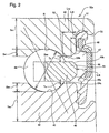
- FIG. 1 through FIG. 3 illustrate a first example of an embodiment of the present invention, corresponding to a first aspect, a second aspect, a third aspect and a fourth aspect.
- FIG 1 and FIG 2 illustrate the proportions of individual parts are drawn to match the actual proportions.
- an outer ring 40 one with an outer diameter D 40 less than or equal to 65 mm (D 40 ⁇ 65 mm) and having a double row outer ring raceway 41 on the inner circumferential surface is used.
- an inner ring 42 one having a double row inner ring raceway 43 on the outer circumferential surface is used.
- balls 44 with diameters (outer diameters) D 44 less than or equal to 4 mm (D 44 ⁇ 4 mm) (3 to 4 mm in practice) are used, and are provided between each of the outer ring raceways 41 and each of inner ring raceways 43 in a group of several balls so as to allow free rolling.
- the balls 44 are held in place while allowing them to roll freely, and a pair of seal rings 46 is used to seal the openings on both ends of an inner space 47 which exists between the inner circumferential surface of the outer ring 40 and the outer circumferential surface of the inner ring 42, and accommodates the balls 44.
- a pair of seal rings 46 is used to seal the openings on both ends of an inner space 47 which exists between the inner circumferential surface of the outer ring 40 and the outer circumferential surface of the inner ring 42, and accommodates the balls 44.
- a width W 32 related to the axial direction of the double row ball bearing 32a as a whole is reduced to less than or equal to 45% of an inner diameter R 42 of this inner ring 42 (W 32 ⁇ 0.45 R 42 ).
- the spacing d 44 between the balls 44 can be reduced without being obstructed by the rims 48.
- a distance L 48 between each of the rims 48 and the inside surface of the seal ring 46 is shortened.
- the distance L 48 between the rims 48 and the inside surface of each of the seal rings 46 is ensured to be more than or equal to 13% of the diameter D 44 of the balls 44 (L 48 ⁇ 0.13D 44 ), such that the filling amount of the grease within the inner space 47 accommodating the balls 44 between both of the seal rings 44 can be ensured.
- a concave circular-cone-shaped chamfer 49 is formed on the portion near both ends of the inner circumferential surface of the outer ring 40. That is to say, at both ends of the inner circumferential surface of the outer ring 40, a large diameter portion 50 for which the diameter is larger than the central part is formed, and on an axially inner half of each of the large diameter portions 50, a stopper groove 51 for stoppingly engaging with the outer circumference edge portion of each of the seal rings 46 is formed.
- a chamfer 49 which tapers in a direction of increasing inner diameter as it approaches the large diameter portion 50.
- An axial length L 49 of each of the chamfers is set to more than or equal to 30% of an axial length L 52 (L 49 ⁇ 0.3L 52 ).
- an axial length L 52 L 49 ⁇ 0.3L 52 .
- FIG. 3 two examples of each of the chamfer 49 are illustrated.
- the axial length L 52 of the continuous portion 52 is set to about 1.6 mm and the axial length L 49 of the chamfer 49 is set to about 0.87 mm.
- the axial length L 52 of the continuous portion 52 is set to about 1.1 mm and the axial length L 49 of the chamfer 49 is set to about 0.5 mm.
- an inclination angle ⁇ of the chamfer 49 with respect to the central axis of the outer ring 40 is regulated in such a way as to facilitate the filling of grease into the inner space 47 by utilizing this chamfer 49 as a guide. That is to say, the largest outer diameter D 49 of the chamfer 49 is ensured, and in order for the grease which is pushed with respect to this chamfer 49 during the filling process, to easily flow towards the smaller diameter side of the chamfer 49, the inclination angle is regulated to 30 to 60 degrees. For instance, it is preferable to set the inclination angle to approximately 45 ⁇ 5 degrees.
- chamfers 49a and 49b are also formed on both inner and outer circumferential edges of the outer side face of the rim 48 of each retainer 45.
- Each of these chamfer 49a and 49b also, function as guides for when filling the grease, and contribute to the ensuring of the amount of grease to be filled within the inner space 47.
- a concave part which concaves radially inwards is formed on one part of the outer circumferential surface of the rim 48 of each of the retainers 45, and by accumulating the grease in this concave part it is also possible to ensure the amount of grease to be filled within inner space 47.
- a concave part which concaves radially outwards is formed on one part of the connecting portion 52 existing on the portion near both ends of the inner circumferential surface of the outer ring 40 and by accumulating the grease in this concave part it is also possible to ensure the amount of grease to be filled within inner space 47.
- the positioning of the retainers 45 in the radial direction is each determined by means of ball guidance. That is to say, the inside surface of a pocket 53 of each of the retainers 45 is made into a partial spherical concave surface having a radius of curvature slightly larger than the radius of curvature of the rolling surface of each of the balls 44, such that the inside surface of the pocket 53 closely faces the rolling surface of each of the balls 44.
- each of the balls 44 are supported so as to be able to roll freely, within the pockets 53 and at the same time positioning of the retainers 45 in the radial direction is determined by each of the balls 44.
- each of the retainers 45 is provided with an offset towards the inner diameter side with respect to the pitch circle of each of the balls 44.
- the difference between a pitch circle diameter D P of the plurality of the balls 44 and an inner diameter R 45 of each of the retainers 45 is greater than the difference between an outer diameter D 45 of each of the retainers 45 and the pitch circle diameter ⁇ (D P - R 45 ) > (D 45 - D P ) ⁇ .
- the difference between an inner diameter R 40 of the outer ring 40 and an outer diameter D 45 of each of the retainers 45 is greater than the difference between an inner diameter R 45 of the retainer 45 and an outer diameter D 42 of the inner ring 42 ⁇ (R 40 - D 45 ) > (R 45 - D 42 ) ⁇ .
- each of the retainers 45 is determined by means of ball-guidance in the above manner, and by providing an offset towards the inner diameter side with respect to the pitch circle diameter of the balls 44, it is possible to achieve efficient utilization of the grease that exists within the inner space 47. That is to say, because the radial positioning of the retainers 45 is regulated by means of ball-guidance, gaps 54a and 54b, which are sufficient for the grease to flow through, are formed between both inner and outer circumferential surfaces of each of the retainers 45 and the outer circumferential surface of the inner ring 42 and the inner circumferential surface of the outer ring 40. As a result, through both of these gaps 54a and 54b, the grease can be fed into the rolling contact portion between the rolling surface of each of the balls 44 and each of the outer ring raceways 41 and each of the inner ring raceways 43.
- each of the retainers 45 exists, in the radial direction, on the inner-diameter side relative to the central position (in the present example, the same position as that of the pitch circle of each of the balls 44) between the outer circumferential surface of the inner ring 42 and the inner circumferential surface of the outer ring 40. Therefore, a thickness T b of the gap 54b between the outer circumferential surface of each of the retainers 45 and the inner circumferential surface of the outer ring 40 is greater than a thickness T a of the gap 54a between the inner circumferential surface of each of the retainers 45 and the outer circumferential surface of the inner ring 42 (T b > T a ).
- the grease which is sent radially outward by means of centrifugal force and reaches the inner circumferential surface of the outer ring 40 is fed efficiently to the rolling contact portion between the rolling surface of each of the balls 44 and each of the outer ring raceways 41.
- the grease which adheres to the rolling surface of each of the balls 44 fitted into these rolling contact portions is fed directly to the rolling contact portion between the rolling surface of each of the balls 44 and each of the inner ring raceways 43.
- the lubrication condition of the rolling contact part becomes desirable.
- the thicknesses T 41 and T 43 of the thin portions corresponding to the bottom parts of the outer ring raceway 41 and the inner ring raceways 43 respectively are set to more than or equal to 50% of the diameter D 44 of each of the balls 44 (T 41 , T 43 ⁇ 0.5D 44 ).
- this configuration prevents the internal gap of the double row ball bearing 32a from becoming excessively small (negative absolute value of the internal gap becomes large).
- the thicknesses T 41 and T 43 are ensured for the thin parts corresponding to the bottom of the outer ring raceway 41 and the inner ring raceways 43 respectively, changes in the radial direction of the dimensions of the outer ring 40 and the inner ring 42 are restrained, and degradation of the durability of the double row ball bearing 32a can be prevented.
- the axial length L 44 between the center of each row of the balls 44 and the axial end faces of the outer ring 40 and the inner ring 42 is greater than the pitch P 44 among the rows of the balls 44 arranged in the double row (P 44 ⁇ L 44 ).
- FIG 4 illustrates a second example of an embodiment of the present invention, corresponding to the first aspect and the second aspect.
- standard ball-guidance is used as the structure for determining the radial positioning of the retainers 45a, and the pitch circle of the balls 44 and the radial central position of the retainer 45a are coincided.
- the depth D 41 ' of the outer ring raceways 41 is set shallower than the depth D 43 of the inner ring raceways 43 (D 41 ⁇ D 43 ).
- the thickness T b of the gap 54b between the outer circumferential surface of each of the retainers 45a and the inner circumferential surface of the outer ring 40 is greater than the thickness T a of the gap 54a between the inner circumferential surface of each of the retainers 45a and the outer circumferential surface of the inner ring 42 (T b > T a ).
- the structure of the seal ring 46a is different from the abovementioned first example. Since the configuration and operation of other parts are the same as the first example, duplicated description is omitted.
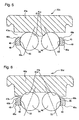
- FIG. 5 illustrates a third example of an embodiment of the present invention, corresponding to a fifth aspect.
- a back-to-back duplex type contact angle is given to each of the balls 44 arranged in the double row.
- the outer ring 40a On the inner circumferential surface of the outer ring 40a, there is formed a pair of outer ring raceways 41a, being angular type with each facing outward in the axial direction.
- the inner diameter of the outer ring 40a on the axially outside of each of the outer ring raceways 41a, being the anti-loading side, is greater than or equal to the largest diameter of each of the outer ring raceways 41a.
- the inner diameter of the outer ring 40a is the smallest at the interval portion between both of the outer ring raceways 41a, and at both outside ends of both of the outer ring raceways 41a, the inner diameter is set larger than the interval portion, such that a so-called groove depth is zero.
- the double row ball bearing 32c of the present example constituted in the above manner, by enlarging the inner diameter of the outer ring 40a at the anti-loading side portion, the static spatial volume is increased, and the amount of grease able to be filled within the inner space 47a can be increased. Furthermore, because the inner diameter is large on the part close to both outside ends of the inner circumferential surface of the outer ring 40a, grease can be easily filled into the inner space 47a, and hence a sufficient amount of grease can be filled into the inner space 47a. As a result, lubrication of the rolling contact portions is also improved, and the durability of the double row ball bearing 32c can be ensured.
- FIG. 6 illustrates a fourth example of an embodiment of the present invention, corresponding to a sixth aspect.
- a face-to-face duplex type contact angle is given to each of the balls 44 arranged in the double row.
- the outer ring 40b On the inner circumferential surface of the outer ring 40b, there is formed a pair of outer ring raceways 41b, being angular type with each facing inwards in the axial direction.
- the inner diameter of the outer ring 40b at the interval portion between the outer ring raceways 41b, being the anti-loading side is greater than the largest diameter of each of the outer ring raceways 41b.
- the inner diameter of the outer ring 40b is the smallest at both outside ends of both of the outer ring raceways 41b, and at the interval portion between both of the outer ring raceways 41b, the inner diameter is set larger than both end portions such that a so-called groove depth is zero.
- the double row ball bearing 32d of the present example constituted in the above manner, by enlarging the inner diameter of the outer ring 40b at the anti-loading side portion, the static spatial volume is increased, and the amount of grease able to be filled within the inner space 47b can be increased. Especially, the grease that flows outward in the radial direction due to the centrifugal force that acts during operation, is collected at the widthwise central part of the outer ring 40b, that is, the portion between both of the outer ring raceways 41b, and hence the grease can be efficiently supplied to the rolling contact portions. As a result, lubrication on the rolling contact portions is also improved, and the durability of the double row ball bearing 32d can be ensured.
- the durability of the pulley support double row ball bearing can be further improved.
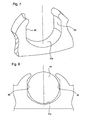
- the retainer one provided with a cylindrical surface portion 55 having a central axis parallel to the central axis of the retainer, on one part of the internal surface of the pocket 53a is used, then ensuring the filling amount of the grease into the inner space, and the efficient supply of grease to each of the rolling contact portions can be performed.
- further improvement in durability of the double row ball bearing can be achieved.
- pulley support double row ball bearing of the present invention is used in the configuration described above, it is possible to contribute to the miniaturization and lightening of various automobile auxiliary equipment such as compressors, while ensuring sufficient durability.
Landscapes
- Engineering & Computer Science (AREA)
- General Engineering & Computer Science (AREA)
- Mechanical Engineering (AREA)
- Manufacturing & Machinery (AREA)
- Rolling Contact Bearings (AREA)
Applications Claiming Priority (3)
| Application Number | Priority Date | Filing Date | Title |
|---|---|---|---|
| JP2002183760 | 2002-06-25 | ||
| JP2002183760 | 2002-06-25 | ||
| PCT/JP2003/007879 WO2004001242A1 (ja) | 2002-06-25 | 2003-06-20 | プーリ支持用複列玉軸受 |
Publications (1)
| Publication Number | Publication Date |
|---|---|
| EP1533533A1 true EP1533533A1 (de) | 2005-05-25 |
Family
ID=29996688
Family Applications (1)
| Application Number | Title | Priority Date | Filing Date |
|---|---|---|---|
| EP03760924A Withdrawn EP1533533A1 (de) | 2002-06-25 | 2003-06-20 | Doppelreihiges kugellager zur abstützung einer scheibe |
Country Status (7)
| Country | Link |
|---|---|
| US (1) | US20060171622A1 (de) |
| EP (1) | EP1533533A1 (de) |
| JP (1) | JPWO2004001242A1 (de) |
| KR (1) | KR100697914B1 (de) |
| CN (1) | CN100343539C (de) |
| AU (1) | AU2003244095A1 (de) |
| WO (1) | WO2004001242A1 (de) |
Cited By (2)
| Publication number | Priority date | Publication date | Assignee | Title |
|---|---|---|---|---|
| US20140079349A1 (en) * | 2012-09-19 | 2014-03-20 | Jtekt Corporation | Rolling bearing |
| ITTO20130893A1 (it) * | 2013-11-04 | 2015-05-05 | Skf Ab | Gruppo integrato tra puleggia e cuscinetto a rotolamento |
Families Citing this family (17)
| Publication number | Priority date | Publication date | Assignee | Title |
|---|---|---|---|---|
| EP1972801B1 (de) * | 2006-01-13 | 2016-03-16 | NSK Ltd. | Balllager für den spindeldrehabschnitt eines maschinenwerkzeugs, und spindeldrehvorrichtung für ein maschinenwerkzeug damit |
| JP5018315B2 (ja) | 2006-09-14 | 2012-09-05 | ソニー株式会社 | 無線通信システム、無線通信装置、無線通信装置の認証方法、および、プログラム |
| JP2010281352A (ja) * | 2008-06-06 | 2010-12-16 | Ntn Corp | 旋回軸受およびその軌道溝加工方法 |
| WO2010150707A1 (ja) * | 2009-06-26 | 2010-12-29 | Ntn株式会社 | 深みぞ玉軸受用の合成樹脂製保持器および深みぞ玉軸受並びにギヤ支持装置 |
| CN102996626B (zh) * | 2012-12-10 | 2017-05-17 | 浙江优特轴承有限公司 | 整体式内圈无沟槽双联滚珠轴承 |
| JP2018028330A (ja) * | 2016-08-15 | 2018-02-22 | 日本精工株式会社 | 玉軸受、及び工作機械用主軸装置 |
| JP2018204681A (ja) * | 2017-06-02 | 2018-12-27 | 株式会社不二越 | 複列4点接触玉軸受 |
| FR3079584A1 (fr) * | 2018-04-03 | 2019-10-04 | Aktiebolaget Skf | Dispositif de poulie pour galet tendeur ou enrouleur |
| FR3079582B1 (fr) * | 2018-04-03 | 2020-04-03 | Aktiebolaget Skf | Dispositif de poulie pour galet tendeur ou enrouleur |
| FR3079586B1 (fr) * | 2018-04-03 | 2020-04-03 | Aktiebolaget Skf | Dispositif de poulie pour galet tendeur ou enrouleur |
| FR3080422B1 (fr) * | 2018-04-19 | 2020-04-03 | Aktiebolaget Skf | Dispositif de poulie pour galet tendeur ou enrouleur |
| FR3082908B1 (fr) * | 2018-06-26 | 2020-06-19 | Aktiebolaget Skf | Dispositif de poulie pour galet tendeur ou enrouleur |
| US11668342B2 (en) | 2019-02-01 | 2023-06-06 | Roller Bearing Company Of America, Inc. | Integrated stud ball bearing with precision matched raceway contact angles for consistent stiffness of gimbal assembly |
| KR102295186B1 (ko) * | 2019-09-24 | 2021-09-01 | (주)세고스 | 베어링 조립체 |
| DE102020205860A1 (de) * | 2020-05-11 | 2021-11-11 | Aktiebolaget Skf | Lageranordnung |
| CN113883257A (zh) * | 2020-07-02 | 2022-01-04 | 浙江万里扬股份有限公司 | 润滑结构和变速器组件 |
| IT202300025137A1 (it) * | 2023-11-27 | 2025-05-27 | Skf Ab | Unita’ cuscinetto a sezione sottile |
Family Cites Families (17)
| Publication number | Priority date | Publication date | Assignee | Title |
|---|---|---|---|---|
| JPS5718810A (en) * | 1980-07-08 | 1982-01-30 | Yasuo Ueno | Ball bearing for high speed rotation |
| JPS5746123U (de) * | 1980-08-29 | 1982-03-13 | ||
| EP0224876A3 (de) * | 1985-12-04 | 1988-01-13 | Delta Drive Technik nach dem Gleitkeilprinzip GmbH | Anordnung mit Wälzelementen |
| JPH0412256Y2 (de) * | 1986-11-29 | 1992-03-25 | ||
| CN2059199U (zh) * | 1989-03-30 | 1990-07-11 | 株洲轴承总厂 | 汽车压缩机用双列密封球轴承 |
| DE4142313C2 (de) * | 1991-12-20 | 1998-10-29 | Schaeffler Waelzlager Ohg | Radial- oder Axialwälzlager aus Stahl |
| JP3419052B2 (ja) * | 1993-12-17 | 2003-06-23 | 日本精工株式会社 | 複列玉軸受と予圧を付与された複列玉軸受の製造方法 |
| JPH07305728A (ja) * | 1994-05-11 | 1995-11-21 | Ntn Corp | 転がり軸受 |
| JPH08270662A (ja) * | 1995-02-03 | 1996-10-15 | Koyo Seiko Co Ltd | 軸受の密封装置 |
| JPH08326655A (ja) | 1995-06-05 | 1996-12-10 | Calsonic Corp | 斜板式コンプレッサ |
| CN2229989Y (zh) * | 1995-09-11 | 1996-06-26 | 中山大学孙文学院 | 汽车空调离合器用双列密封球轴承 |
| JPH1113771A (ja) * | 1997-06-25 | 1999-01-22 | Nippon Seiko Kk | シールリング付転がり軸受 |
| JPH11280644A (ja) | 1998-03-06 | 1999-10-15 | Calsonic Corp | 蒸気圧縮式冷凍機用コンプレッサ |
| CN2361899Y (zh) * | 1998-12-24 | 2000-02-02 | 瓦房店重型轧机轴承厂 | 双列大角接触球轴承 |
| JP2002024863A (ja) | 2000-06-30 | 2002-01-25 | Tomohiko Sugimoto | 景観画像表示システム |
| JP2002097966A (ja) | 2000-09-26 | 2002-04-05 | Zenshin Denryoku Engineering:Kk | ガスタービン発電機の運転方法 |
| JP4834921B2 (ja) * | 2001-01-30 | 2011-12-14 | 日本精工株式会社 | コンプレッサ用プーリの回転支持装置 |
-
2003
- 2003-06-20 WO PCT/JP2003/007879 patent/WO2004001242A1/ja not_active Ceased
- 2003-06-20 AU AU2003244095A patent/AU2003244095A1/en not_active Abandoned
- 2003-06-20 EP EP03760924A patent/EP1533533A1/de not_active Withdrawn
- 2003-06-20 US US10/519,225 patent/US20060171622A1/en not_active Abandoned
- 2003-06-20 CN CNB038179989A patent/CN100343539C/zh not_active Expired - Fee Related
- 2003-06-20 JP JP2004515538A patent/JPWO2004001242A1/ja active Pending
- 2003-06-20 KR KR1020047021020A patent/KR100697914B1/ko not_active Expired - Fee Related
Non-Patent Citations (1)
| Title |
|---|
| See references of WO2004001242A1 * |
Cited By (4)
| Publication number | Priority date | Publication date | Assignee | Title |
|---|---|---|---|---|
| US20140079349A1 (en) * | 2012-09-19 | 2014-03-20 | Jtekt Corporation | Rolling bearing |
| US8858086B2 (en) * | 2012-09-19 | 2014-10-14 | Jtekt Corporation | Rolling bearing |
| ITTO20130893A1 (it) * | 2013-11-04 | 2015-05-05 | Skf Ab | Gruppo integrato tra puleggia e cuscinetto a rotolamento |
| EP2868939A1 (de) * | 2013-11-04 | 2015-05-06 | Aktiebolaget SKF | Riemenscheibenlageranordnung |
Also Published As
| Publication number | Publication date |
|---|---|
| WO2004001242A1 (ja) | 2003-12-31 |
| JPWO2004001242A1 (ja) | 2005-10-20 |
| KR20050022014A (ko) | 2005-03-07 |
| AU2003244095A1 (en) | 2004-01-06 |
| CN100343539C (zh) | 2007-10-17 |
| CN1671973A (zh) | 2005-09-21 |
| KR100697914B1 (ko) | 2007-03-20 |
| US20060171622A1 (en) | 2006-08-03 |
Similar Documents
| Publication | Publication Date | Title |
|---|---|---|
| EP2290249B1 (de) | Doppelreihiges Kugellager für Scheibenträger | |
| US20060171622A1 (en) | Double-row ball bearing for supporting pulley | |
| KR100679909B1 (ko) | 사판식 압축기 | |
| US20070081904A1 (en) | Variable displacement type compressor | |
| JP5093577B2 (ja) | スラスト針状ころ軸受 | |
| JP2005054895A (ja) | ニードル軸受用の保持器及びニードル軸受 | |
| JP4314511B2 (ja) | スラストニードル軸受 | |
| JP2008064184A (ja) | スラスト針状ころ軸受 | |
| US20140241925A1 (en) | Swash plate compressor | |
| EP0971128A2 (de) | Verdrängungskompressor für Kältemittel mit Ölabscheidungs- und Schmiersystem | |
| JP2005076780A (ja) | スラストニードル軸受 | |
| JP2005076848A (ja) | スラストニードル軸受及びカーエアコン用コンプレッサ | |
| KR20210110463A (ko) | 압축기 | |
| JP2005009526A (ja) | スラストニードル軸受、ころ及びカーエアコン用コンプレッサ | |
| JP2004340258A (ja) | ニードル軸受用の保持器及びニードル軸受 | |
| KR100728412B1 (ko) | 풀리 지지용 복열 볼베어링 | |
| JP2005076847A (ja) | スラストニードル軸受及びカーエアコン用コンプレッサ | |
| JP2003314441A (ja) | 斜板式圧縮機 | |
| JP2005042789A (ja) | ニードル軸受及びカークーラコンプレッサ | |
| JP2010084588A (ja) | 圧縮機プーリ構造 | |
| JP2008038987A (ja) | スラストニードル軸受 | |
| JP2005220959A (ja) | スラストニードル軸受用の保持器、スラストニードル軸受及びカークーラコンプレッサ | |
| JP2005076779A (ja) | スラストニードル軸受 | |
| JP2005201072A (ja) | ニードル軸受及びカークーラコンプレッサ | |
| JP2008057750A (ja) | スラスト針状ころ軸受 |
Legal Events
| Date | Code | Title | Description |
|---|---|---|---|
| PUAI | Public reference made under article 153(3) epc to a published international application that has entered the european phase |
Free format text: ORIGINAL CODE: 0009012 |
|
| 17P | Request for examination filed |
Effective date: 20050110 |
|
| AK | Designated contracting states |
Kind code of ref document: A1 Designated state(s): AT BE BG CH CY CZ DE DK EE ES FI FR GB GR HU IE IT LI LU MC NL PT RO SE SI SK TR |
|
| AX | Request for extension of the european patent |
Extension state: AL LT LV MK |
|
| DAX | Request for extension of the european patent (deleted) | ||
| STAA | Information on the status of an ep patent application or granted ep patent |
Free format text: STATUS: THE APPLICATION IS DEEMED TO BE WITHDRAWN |
|
| 18D | Application deemed to be withdrawn |
Effective date: 20100105 |