EP1533399B1 - Verfahren zum abwasserarmen Betrieb eines alkalischen Zink-Nickel-Bades - Google Patents
Verfahren zum abwasserarmen Betrieb eines alkalischen Zink-Nickel-Bades Download PDFInfo
- Publication number
- EP1533399B1 EP1533399B1 EP04027712A EP04027712A EP1533399B1 EP 1533399 B1 EP1533399 B1 EP 1533399B1 EP 04027712 A EP04027712 A EP 04027712A EP 04027712 A EP04027712 A EP 04027712A EP 1533399 B1 EP1533399 B1 EP 1533399B1
- Authority
- EP
- European Patent Office
- Prior art keywords
- electrolyte
- catholyte
- bath
- evaporator
- purified
- Prior art date
- Legal status (The legal status is an assumption and is not a legal conclusion. Google has not performed a legal analysis and makes no representation as to the accuracy of the status listed.)
- Expired - Lifetime
Links
- 238000000034 method Methods 0.000 title claims description 32
- QELJHCBNGDEXLD-UHFFFAOYSA-N nickel zinc Chemical compound [Ni].[Zn] QELJHCBNGDEXLD-UHFFFAOYSA-N 0.000 title claims description 17
- 239000002351 wastewater Substances 0.000 title claims description 11
- 239000003792 electrolyte Substances 0.000 claims abstract description 68
- 150000003467 sulfuric acid derivatives Chemical class 0.000 claims abstract description 20
- 238000001556 precipitation Methods 0.000 claims abstract description 13
- 239000012074 organic phase Substances 0.000 claims abstract description 11
- 239000003795 chemical substances by application Substances 0.000 claims abstract 2
- PXHVJJICTQNCMI-UHFFFAOYSA-N Nickel Chemical compound [Ni] PXHVJJICTQNCMI-UHFFFAOYSA-N 0.000 claims description 30
- 239000008139 complexing agent Substances 0.000 claims description 18
- 229910052759 nickel Inorganic materials 0.000 claims description 13
- QAOWNCQODCNURD-UHFFFAOYSA-L Sulfate Chemical compound [O-]S([O-])(=O)=O QAOWNCQODCNURD-UHFFFAOYSA-L 0.000 claims description 9
- 238000001704 evaporation Methods 0.000 claims description 7
- 230000008020 evaporation Effects 0.000 claims description 7
- 239000002244 precipitate Substances 0.000 claims description 7
- 150000003839 salts Chemical class 0.000 claims description 7
- VEQPNABPJHWNSG-UHFFFAOYSA-N Nickel(2+) Chemical compound [Ni+2] VEQPNABPJHWNSG-UHFFFAOYSA-N 0.000 claims description 5
- 238000000576 coating method Methods 0.000 claims description 5
- 239000003014 ion exchange membrane Substances 0.000 claims description 5
- 229910001453 nickel ion Inorganic materials 0.000 claims description 5
- 239000008237 rinsing water Substances 0.000 claims description 4
- PTFCDOFLOPIGGS-UHFFFAOYSA-N Zinc dication Chemical compound [Zn+2] PTFCDOFLOPIGGS-UHFFFAOYSA-N 0.000 claims description 3
- 239000011248 coating agent Substances 0.000 claims description 3
- 150000002500 ions Chemical class 0.000 claims description 2
- 230000001376 precipitating effect Effects 0.000 claims 6
- 238000009713 electroplating Methods 0.000 claims 3
- 238000011010 flushing procedure Methods 0.000 claims 1
- 238000012423 maintenance Methods 0.000 claims 1
- 239000012141 concentrate Substances 0.000 abstract description 5
- 238000000746 purification Methods 0.000 abstract description 5
- 239000012528 membrane Substances 0.000 description 14
- HEMHJVSKTPXQMS-UHFFFAOYSA-M Sodium hydroxide Chemical compound [OH-].[Na+] HEMHJVSKTPXQMS-UHFFFAOYSA-M 0.000 description 11
- XLYOFNOQVPJJNP-UHFFFAOYSA-N water Substances O XLYOFNOQVPJJNP-UHFFFAOYSA-N 0.000 description 10
- XFXPMWWXUTWYJX-UHFFFAOYSA-N Cyanide Chemical compound N#[C-] XFXPMWWXUTWYJX-UHFFFAOYSA-N 0.000 description 9
- 239000000047 product Substances 0.000 description 8
- 239000000243 solution Substances 0.000 description 8
- 239000002699 waste material Substances 0.000 description 8
- 238000004140 cleaning Methods 0.000 description 7
- 239000012071 phase Substances 0.000 description 5
- PMZURENOXWZQFD-UHFFFAOYSA-L Sodium Sulfate Chemical compound [Na+].[Na+].[O-]S([O-])(=O)=O PMZURENOXWZQFD-UHFFFAOYSA-L 0.000 description 4
- 150000001412 amines Chemical class 0.000 description 4
- 238000001816 cooling Methods 0.000 description 4
- 239000007857 degradation product Substances 0.000 description 4
- 238000010525 oxidative degradation reaction Methods 0.000 description 4
- 235000011121 sodium hydroxide Nutrition 0.000 description 4
- 229910052938 sodium sulfate Inorganic materials 0.000 description 4
- 235000011152 sodium sulphate Nutrition 0.000 description 4
- 239000000126 substance Substances 0.000 description 4
- 238000004065 wastewater treatment Methods 0.000 description 4
- MUBZPKHOEPUJKR-UHFFFAOYSA-N Oxalic acid Chemical compound OC(=O)C(O)=O MUBZPKHOEPUJKR-UHFFFAOYSA-N 0.000 description 3
- 230000002411 adverse Effects 0.000 description 3
- 238000006243 chemical reaction Methods 0.000 description 3
- 238000010790 dilution Methods 0.000 description 3
- 239000012895 dilution Substances 0.000 description 3
- 230000010354 integration Effects 0.000 description 3
- 239000000203 mixture Substances 0.000 description 3
- BVKZGUZCCUSVTD-UHFFFAOYSA-L Carbonate Chemical compound [O-]C([O-])=O BVKZGUZCCUSVTD-UHFFFAOYSA-L 0.000 description 2
- QAOWNCQODCNURD-UHFFFAOYSA-N Sulfuric acid Chemical compound OS(O)(=O)=O QAOWNCQODCNURD-UHFFFAOYSA-N 0.000 description 2
- RQPZNWPYLFFXCP-UHFFFAOYSA-L barium dihydroxide Chemical compound [OH-].[OH-].[Ba+2] RQPZNWPYLFFXCP-UHFFFAOYSA-L 0.000 description 2
- 229910001863 barium hydroxide Inorganic materials 0.000 description 2
- 238000003287 bathing Methods 0.000 description 2
- 238000010276 construction Methods 0.000 description 2
- 238000002425 crystallisation Methods 0.000 description 2
- 230000008025 crystallization Effects 0.000 description 2
- 230000006378 damage Effects 0.000 description 2
- 238000000354 decomposition reaction Methods 0.000 description 2
- 230000008021 deposition Effects 0.000 description 2
- 238000005516 engineering process Methods 0.000 description 2
- 239000002184 metal Substances 0.000 description 2
- 229910052751 metal Inorganic materials 0.000 description 2
- 239000005486 organic electrolyte Substances 0.000 description 2
- 230000001590 oxidative effect Effects 0.000 description 2
- 238000004064 recycling Methods 0.000 description 2
- 238000012958 reprocessing Methods 0.000 description 2
- 239000007787 solid Substances 0.000 description 2
- 239000011701 zinc Substances 0.000 description 2
- DGAQECJNVWCQMB-PUAWFVPOSA-M Ilexoside XXIX Chemical compound C[C@@H]1CC[C@@]2(CC[C@@]3(C(=CC[C@H]4[C@]3(CC[C@@H]5[C@@]4(CC[C@@H](C5(C)C)OS(=O)(=O)[O-])C)C)[C@@H]2[C@]1(C)O)C)C(=O)O[C@H]6[C@@H]([C@H]([C@@H]([C@H](O6)CO)O)O)O.[Na+] DGAQECJNVWCQMB-PUAWFVPOSA-M 0.000 description 1
- 230000002378 acidificating effect Effects 0.000 description 1
- -1 aliphatic amines Chemical class 0.000 description 1
- 239000003513 alkali Substances 0.000 description 1
- 239000000956 alloy Substances 0.000 description 1
- 229910045601 alloy Inorganic materials 0.000 description 1
- 239000008346 aqueous phase Substances 0.000 description 1
- 230000015572 biosynthetic process Effects 0.000 description 1
- 230000007423 decrease Effects 0.000 description 1
- 238000001514 detection method Methods 0.000 description 1
- 238000001784 detoxification Methods 0.000 description 1
- 230000001627 detrimental effect Effects 0.000 description 1
- 238000009792 diffusion process Methods 0.000 description 1
- 230000000694 effects Effects 0.000 description 1
- 238000001914 filtration Methods 0.000 description 1
- 238000005259 measurement Methods 0.000 description 1
- LGQLOGILCSXPEA-UHFFFAOYSA-L nickel sulfate Chemical compound [Ni+2].[O-]S([O-])(=O)=O LGQLOGILCSXPEA-UHFFFAOYSA-L 0.000 description 1
- BFDHFSHZJLFAMC-UHFFFAOYSA-L nickel(ii) hydroxide Chemical compound [OH-].[OH-].[Ni+2] BFDHFSHZJLFAMC-UHFFFAOYSA-L 0.000 description 1
- 239000005416 organic matter Substances 0.000 description 1
- 230000002035 prolonged effect Effects 0.000 description 1
- 238000000926 separation method Methods 0.000 description 1
- 239000010802 sludge Substances 0.000 description 1
- 229910052708 sodium Inorganic materials 0.000 description 1
- 239000011734 sodium Substances 0.000 description 1
- 238000007738 vacuum evaporation Methods 0.000 description 1
- 239000003643 water by type Substances 0.000 description 1
Images


Classifications
-
- C—CHEMISTRY; METALLURGY
- C02—TREATMENT OF WATER, WASTE WATER, SEWAGE, OR SLUDGE
- C02F—TREATMENT OF WATER, WASTE WATER, SEWAGE, OR SLUDGE
- C02F1/00—Treatment of water, waste water, or sewage
- C02F1/02—Treatment of water, waste water, or sewage by heating
- C02F1/04—Treatment of water, waste water, or sewage by heating by distillation or evaporation
- C02F1/048—Purification of waste water by evaporation
-
- B—PERFORMING OPERATIONS; TRANSPORTING
- B01—PHYSICAL OR CHEMICAL PROCESSES OR APPARATUS IN GENERAL
- B01D—SEPARATION
- B01D61/00—Processes of separation using semi-permeable membranes, e.g. dialysis, osmosis or ultrafiltration; Apparatus, accessories or auxiliary operations specially adapted therefor
- B01D61/42—Electrodialysis; Electro-osmosis ; Electro-ultrafiltration; Membrane capacitive deionization
- B01D61/44—Ion-selective electrodialysis
-
- C—CHEMISTRY; METALLURGY
- C25—ELECTROLYTIC OR ELECTROPHORETIC PROCESSES; APPARATUS THEREFOR
- C25D—PROCESSES FOR THE ELECTROLYTIC OR ELECTROPHORETIC PRODUCTION OF COATINGS; ELECTROFORMING; APPARATUS THEREFOR
- C25D17/00—Constructional parts, or assemblies thereof, of cells for electrolytic coating
- C25D17/002—Cell separation, e.g. membranes, diaphragms
-
- C—CHEMISTRY; METALLURGY
- C25—ELECTROLYTIC OR ELECTROPHORETIC PROCESSES; APPARATUS THEREFOR
- C25D—PROCESSES FOR THE ELECTROLYTIC OR ELECTROPHORETIC PRODUCTION OF COATINGS; ELECTROFORMING; APPARATUS THEREFOR
- C25D21/00—Processes for servicing or operating cells for electrolytic coating
- C25D21/16—Regeneration of process solutions
- C25D21/18—Regeneration of process solutions of electrolytes
-
- C—CHEMISTRY; METALLURGY
- C25—ELECTROLYTIC OR ELECTROPHORETIC PROCESSES; APPARATUS THEREFOR
- C25D—PROCESSES FOR THE ELECTROLYTIC OR ELECTROPHORETIC PRODUCTION OF COATINGS; ELECTROFORMING; APPARATUS THEREFOR
- C25D3/00—Electroplating: Baths therefor
- C25D3/02—Electroplating: Baths therefor from solutions
- C25D3/56—Electroplating: Baths therefor from solutions of alloys
- C25D3/562—Electroplating: Baths therefor from solutions of alloys containing more than 50% by weight of iron or nickel or cobalt
-
- C—CHEMISTRY; METALLURGY
- C02—TREATMENT OF WATER, WASTE WATER, SEWAGE, OR SLUDGE
- C02F—TREATMENT OF WATER, WASTE WATER, SEWAGE, OR SLUDGE
- C02F1/00—Treatment of water, waste water, or sewage
- C02F1/22—Treatment of water, waste water, or sewage by freezing
-
- C—CHEMISTRY; METALLURGY
- C02—TREATMENT OF WATER, WASTE WATER, SEWAGE, OR SLUDGE
- C02F—TREATMENT OF WATER, WASTE WATER, SEWAGE, OR SLUDGE
- C02F1/00—Treatment of water, waste water, or sewage
- C02F1/42—Treatment of water, waste water, or sewage by ion-exchange
-
- C—CHEMISTRY; METALLURGY
- C02—TREATMENT OF WATER, WASTE WATER, SEWAGE, OR SLUDGE
- C02F—TREATMENT OF WATER, WASTE WATER, SEWAGE, OR SLUDGE
- C02F1/00—Treatment of water, waste water, or sewage
- C02F1/68—Treatment of water, waste water, or sewage by addition of specified substances, e.g. trace elements, for ameliorating potable water
- C02F1/683—Treatment of water, waste water, or sewage by addition of specified substances, e.g. trace elements, for ameliorating potable water by addition of complex-forming compounds
-
- C—CHEMISTRY; METALLURGY
- C02—TREATMENT OF WATER, WASTE WATER, SEWAGE, OR SLUDGE
- C02F—TREATMENT OF WATER, WASTE WATER, SEWAGE, OR SLUDGE
- C02F2101/00—Nature of the contaminant
- C02F2101/10—Inorganic compounds
- C02F2101/101—Sulfur compounds
-
- C—CHEMISTRY; METALLURGY
- C02—TREATMENT OF WATER, WASTE WATER, SEWAGE, OR SLUDGE
- C02F—TREATMENT OF WATER, WASTE WATER, SEWAGE, OR SLUDGE
- C02F2103/00—Nature of the water, waste water, sewage or sludge to be treated
- C02F2103/16—Nature of the water, waste water, sewage or sludge to be treated from metallurgical processes, i.e. from the production, refining or treatment of metals, e.g. galvanic wastes
Definitions
- the invention relates to a method for low-effluent operation of an alkaline zinc-nickel bath and a system for bath care.
- Alkaline zinc-nickel baths have the advantage over acidic that the nickel contents in the alloy layers remain substantially constant even at low current densities, which is a particular advantage for drumware.
- alkaline zinc-nickel electrolytes have a better metal distribution. Because of these advantages, alkaline zinc-nickel electrolytes are widely and preferably used. Alkaline zinc-nickel electrolytes must contain complexing agents such as aliphatic amines which keep the nickel ions in solution. If no complexing agents were used, the nickel would precipitate as nickel hydroxide. Therefore, complexing agents are mandatory.
- the alkaline zinc-nickel baths known in the prior art have some disadvantages due to this need.
- the electrolytes known in the prior art have a short service life, which results in an uneven layer thickness buildup. Therefore, the electrolyte must be regularly renewed and disposed of (about 1000I / week).
- Another disadvantage of these baths in terms of their economics is also the observed volume increase in the operation of the bath.
- the volume increase is due to the required dosage of caustic soda solution, nickel complex solution and brightener.
- An overview is in Fig. 2 shown. So far, the volume increase was perceived as a disadvantage only to a limited extent, since the increase dilutes the cyanide inevitably produced in the bath.
- Membrane technology has therefore significantly improved the previously known alkaline zinc-nickel baths.
- the problem of volume increase of the bath persists. This is a problem because the increase significantly increases the amount of waste water to be disposed of.
- complexing agents inevitably accumulate since nickel is supplied to the bath in combination with complexing agents and nickel, but not the complexing agent, is constantly consumed in the deposition of the layer. Too high a concentration of complexing agent has a detrimental effect on the quality of the layers, since they can accumulate on the cathode and oil out there. During oiling out, a film is formed on the cathode surface which prevents further deposition of metal and thereby severely degrades the quality of the deposited coating. This one gets rough and dull.
- the present invention is therefore based on the object to provide a method and a system for operating an alkaline zinc-nickel bath available, with which wastewater quantities can be saved and by which enriched substances that hinder the operation of the bath, can be removed ,
- the alkaline bath to be operated from which the zinc-nickel coatings are electrodeposited, has the typical construction with an anode and a cathode. It also has an ion exchange membrane which separates the anolyte from the alkaline catholyte.
- the alkaline catholyte which corresponds to the actual zinc-nickel electrolyte, has the usual chemistry, so u.a. Zinc ions, nickel ions and complexing agents, in particular to keep the nickel ions in the alkaline in solution.
- the purification of the electrolyte is carried out according to the invention by passing the catholyte (zinc-nickel electrolyte) to be purified into an evaporator where it is concentrated. Surprisingly, it has been shown that not only the electrolyte is concentrated thereby, but also the solubility of the complexing agents decreases. Once the electrolyte is sufficiently concentrated, the excess amines are no longer soluble. At this point, a phase forms on the electrolyte in which the organics float. This organic phase can be easily separated from the electrolyte. According to the invention, the electrolyte is freed from excess sulphates by being precipitated and disposed of.
- the inventively liberated from the excess organics and salts and thus regenerated electrolyte can be recycled and recycled to the catholyte.
- This has the advantage that the process allows a circulation and wastewater and electrolyte quantities are saved.
- Such recycling is known in the art Electrolytes not possible.
- the bath care according to the invention has the consequence that the possible high current yields (about 70%) remain constant over a long period of time. This reduces the required exposure times and consequently significantly increases the coating capacity.
- the evaporation and precipitation of waste products is also energy efficient and environmentally friendly.
- the concentrated waste products can be easily disposed of.
- the cleaning process according to the invention can be easily integrated into existing operating processes.
- precipitation comprises both the precipitation of the sulfates by addition of precipitants (for example barium hydroxide) and the precipitation without such addition.
- precipitants for example barium hydroxide
- the electrolyte to be purified is first freed from the organic phase after evaporation.
- the aqueous, sulfate-rich, concentrated electrolyte is then passed into a crystallizer and cooled in this. Cooling to temperatures below 10 ° C, preferably + -3 to + -4 ° has proved to be advantageous.
- the sulfate precipitates spontaneously with the respective counterion of the lye - for example sodium sulfate in the case of the use of NaOH - and can be removed in a simple manner, for example by filtration.
- the resulting salt load can be disposed of as a solid. This facilitates disposal over the voluminous aqueous wastes.
- the concentrated electrolyte is fed again to an evaporator for further purification and liberation of sulfate.
- the sodium sulfate precipitates at room temperature, so that advantageously no cooling is necessary.
- the removal of the organics and the precipitation of the sulfates is carried out in one step. It has surprisingly been found that when the electrolyte to be purified is evaporated long enough, not only an organic phase is formed, but also the sulfates precipitate with the counterion of the alkali, usually sodium. Details are in Fig. 6 described. This variant is preferred because the cleaning can be done in one step.
- the spent organics which is present as an oily phase, can be disposed of cost-effectively due to the high concentration. A load on the wastewater is prevented. According to a further variant, the organic phase can be returned to the nickel mixture after appropriate treatment.
- the distillate produced by the evaporation process is fed to the rinse water. This increases the process economy.
- the rinse water also contains recyclable electrolyte components. According to an advantageous development, therefore, the rinse water is fed to an evaporator and concentrated. The resulting concentrate can in turn be supplied to the electrolyte and thus the circulation, the distillate is preferably recycled back to the rinse water. This is especially economical. For example, from about 1000 l rinsing water 10-100 l concentrate can be obtained. The additional reprocessing of the rinse water is especially from ecological An advantage because the wastewater is less polluted and less waste is produced.
- the anode is disposed in an anode box. Due to the required rinsing of the membrane box, dilution of the catholyte (electrolyte) occurs as the membrane, because of its semipermeability, is permeable to water and migrates it into the electrolyte. This resulted in the operation of the bath to an adverse dilution of the catholyte (Zi-Ni electrolyte).
- the dilution can be compensated by the described evaporator technology on the one hand.
- a further improvement can be achieved according to an advantageous development of the invention in that the flooding of the anolyte was no longer carried out continuously but clocked.
- Fig. 1 shows the products formed by the oxidative degradation of the complexing agent at the anode. These degradation products reduce the current efficiency and thus the performance of the bath. Furthermore, they complicate the wastewater treatment, as cyanide, oxalate and carbonate arise. In particular, the formation of cyanide leads to a significant overhead in wastewater treatment. These degradation products are formed in the known in the prior art alkaline zinc-nickel baths, which are operated without an ion exchange membrane.
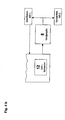
- Fig. 3 shows the basic bath construction.
- the anode 2 is separated from the cathode 3 by a membrane 4.
- the anolyte 5 in which the anode reaction takes place is separated from the catholyte-constituting Zi-Ni electrolyte 6.
- Anolyte 5 consists of dilute sulfuric acid; Preferably, the anolyte contains from 5 100 g / l of H2SO. 4
- the in Fig. 1 illustrated oxidative destruction of complex-forming amines contained in the electrolyte. This can be saved on the one hand chemistry.
- no oxidative degradation products are formed more, so that advantageously no sludge to be disposed of is obtained. Furthermore, this results in a lower carry-over, since the electrolyte is continuously low viscous.
- the membrane is preferably one such as that described in U.S. Pat DE 198 34 353 is described.
- the relevant disclosure is hereby incorporated in full in the description of the present invention.
- the bathroom can either be like in Fig. 3 shown having a membrane. It is also possible to provide the bath with several membrane units. These preferably consist of boxes containing both the anode and the membrane. The cathodes are then placed between the membrane units. This has the advantage that the efficiency is increased and spent or damaged membranes can be easily and inexpensively replaced.
- Fig. 4a shows the cleaning process according to an embodiment.
- the electrolyte 7 to be purified is fed to an evaporator 8 and concentrated.
- the evaporator preferably operates with vacuum evaporation with heat pump principle.
- the distillate is in turn fed to the rinse water.
- the concentrated electrolyte 9 has several phases. Due to the increasing by the concentration of sodium hydroxide content, the complex-forming amine is no longer soluble in the electrolyte. As a result, an upper phase 9a is formed, which contains the organics. This phase can be decanted off, which separates the organic from the rest of the electrolyte.
- the remaining aqueous phase 9b represents the low-organic electrolyte. However, this still contains sulfates - or the corresponding salt components of the nickel - which adversely affect the bath composition.
- the low-organic electrolyte 9b is guided into a crystallizer 10.
- the crystallizer 10 separates by cooling to about + -3 ° C the electrolyte 9b in two parts. Crystallization of the solids creates a salt load that can be easily disposed of.
- a significant saving in wastewater and costs is achieved and the bath can be performed in a cost-effective and environmentally conscious circulation process.
- the resulting monoconcentrates can be handed over to specialized companies for disposal or reprocessing.
- the concentration of sulfate of 60-65 g / l can be reduced to about 30-35 g / l - as desired - so that it is again in an acceptable range.
- Fig. 4b shows a further variant in which also the rinsing waters are concentrated by evaporation.
- the rinsing waters are concentrated by evaporation.
- the concentrate can in turn be fed to the catholyte of the bath, the distillate to the rinse water as shown.
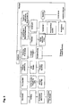
- Fig. 5 shows the integration of the cleaning process according to the invention in the overall system for the operation of the alkaline zinc-nickel bath.
- the treatment of the electrolyte is preferably carried out batchwise.
- the purification of the electrolyte by evaporation and crystallization is preferably carried out once a week for one day.
- the management of the bathing business will be explained on the basis of a 20 000 I electrolyte.
- the volume of the same increases by the in Fig. 2 Volume increase after four weeks already to about 25 000 I.
- the sulfate concentration increases by the addition of the nickel solution continuously to about 60-65g / l in the electrolyte and must be lowered.
- the added 5000 I are concentrated by 3000 l. 2000 l of the electrolyte purified according to the method according to the invention are in turn supplied to the bath. The remaining approx. 3000 l of distillate are fed to the rinsing water. After a week, 5000 of the 22,000 I are again removed for cleaning. The difference of 3000 I is compensated by adding 3000 l of fresh electrolyte. This in turn creates a total volume of 20,000 l and 5000 l can in turn be subjected to the cleaning process according to the invention.
- Fig. 6 shows a preferred Auftheseschange in which the electrolyte to be purified is passed into an evaporator, not shown, and is evaporated until the organic phase forms both, and the sulfates precipitate with the counterion of the liquor. After evaporation, three layers are formed. Two cloudy, mushy homogeneous layers of sodium sulfate and organic 13a and 13b and the organics and sulfatarme purified electrolyte 13c. For example, these layers can be over Filter system 15 are separated by first through a discharge port 14, the cloudy waste 13 b is discharged. As soon as the clear electrolyte 13c comes, it is collected in a container 16 and returned to the catholyte of the bath.
- the detection of the electrolyte 13c may be performed, for example, by a worker, or by a photodiode that can discriminate between waste 13a and 13c and purified electrolyte 13c due to the degree of turbidity. A determination of the measurement of the conductivity would be possible.
Landscapes
- Chemical & Material Sciences (AREA)
- Engineering & Computer Science (AREA)
- Chemical Kinetics & Catalysis (AREA)
- Organic Chemistry (AREA)
- Electrochemistry (AREA)
- Materials Engineering (AREA)
- Metallurgy (AREA)
- Water Supply & Treatment (AREA)
- Urology & Nephrology (AREA)
- Health & Medical Sciences (AREA)
- Life Sciences & Earth Sciences (AREA)
- Hydrology & Water Resources (AREA)
- Environmental & Geological Engineering (AREA)
- Electrolytic Production Of Metals (AREA)
- Inorganic Compounds Of Heavy Metals (AREA)
- Heat Treatment Of Water, Waste Water Or Sewage (AREA)
Description
- Die Erfindung betrifft ein Verfahren zum abwasserarmen Betrieb eines alkalischen Zink-Nickel-Bades sowie ein System zur Badpflege.
- Alkalische Zink-Nickel-Bäder haben gegenüber sauren den Vorteil, dass die Nickelgehalte in den Legierungsschichten auch bei niedrigen Stromdichten im wesentlichen konstant bleiben, was einen besonderen Vorteil für Trommelware darstellt. Zudem weisen alkalische Zink-Nickel-Elektrolyte eine bessere Metallverteilung auf. Aufgrund dieser Vorteile werden alkalische Zink-Nickel-Elektrolyte weitreichend und bevorzugt eingesetzt. Alkalische Zink-Nickel-Elektrolyte müssen Komplexbildner, wie beispielsweise aliphatische Amine enthalten, die die Nickel-Ionen in Lösung halten. Sofern keine Komplexbildner eingesetzt würden, würde das Nickel als Nickelhydroxid ausfallen. Daher sind Komplexbildner zwingend erforderlich. Die im Stand der Technik bekannten alkalischen Zink-Nickel-Bäder haben aufgrund dieser Notwendigkeit jedoch einige Nachteile.
- Nach wenigen Wochen Badbetrieb kann Cyanid im alkalischen Elektrolyten nachgewiesen werden, obwohl der Elektrolyt an sich cyanidfrei ist. Die Cyanid-Entwicklung ist auf den oxidativen Abbau des Komplexbildners an der Anode zurückzuführen. Die durch diesen entstehenden Produkte senken die Stromausbeute und somit die Leistungsfähigkeit des Bades und erschweren die Abwasserbehandlung. Neben dem Cyanid entstehen des weiteren Oxalat und Carbonat als Abbauprodukte des Komplexbildners. Eine Übersicht ist in
Fig. 1 gezeigt. Die Cyanid-Belastung erfordert ein regelmäßiges Erneuern des Bades und eine spezielle Abwasserbehandlung, die sich erheblich auf die Betriebskosten des Bades auswirkt. Dies gilt umso mehr, als die Abwässer zudem eine sehr hohe Organik-Konzentration aufweisen und mit einem CSB-Wert von ca. 15 000 bis 20 000 mg/l die Cyanid-Entgiftung erschweren. Die Einhaltung der vom Gesetzgeber vorgegebenen Abwasserwerte ist dann nur noch durch umfangreichen Zusatz von Chemikalien möglich. - Insgesamt haben die im Stand der Technik bekannten Elektrolyten eine geringe Standzeit, was einen ungleichmäßigen Schichtdickenaufbau zur Folge hat. Daher muß der Elektrolyt regelmäßig erneuert und entsorgt werden (ca. 1000I/Woche). Ein weiterer Nachteil dieser Bäder in bezug auf ihre Ökonomie ist auch die zu beobachtende Volumenzunahme beim Betrieb des Bades. Die Volumenzunahme ist bedingt durch die erforderliche Dosierung von Natronlauge, Nickel-Komplex-Lösung und Glanzbildner. Eine Übersicht ist in
Fig. 2 gezeigt. Bislang wurde die Volumenzunahme nur bedingt als Nachteil empfunden, da durch die Zunahme das im Bad zwangsläufig entstehende Cyanid verdünnt wurde. - Die Probleme im Hinblick auf die Abbauprodukte wurden bereits in vorteilhafter Weise durch eine Ionenaustauschermembran gelöst. Das Prinzip ist in
DE 198 34 353 beschrieben. Die Membran verhindert die oxidative Zerstörung der Amine, wodurch die Abbauprodukte, wie insbesondere Cyanid und Oxalat, auch über einen längeren Betrieb des Bades nicht nachweisbar sind. - Die Membrantechnologie hat daher die zuvor bekannten alkalischen Zink-Nickel-Bäder bedeutend verbessert. Jedoch bleibt das Problem der Volumenzunahme des Bades bestehen. Dies ist ein Problem, da die Zunahme die zu entsorgenden Abwassermengen erheblich erhöht. Des weiteren reichern sich auch bei Einsatz der Membran zwangsläufig Komplexbildner an, da Nickel dem Bad in Kombination mit Komplexbildnern zugeführt wird und Nickel - nicht jedoch der Komplexbildner - ständig bei der Abscheidung der Schicht verbraucht wird. Eine zu hohe Konzentration an Komplexbildner hat nachteilige Auswirkungen auf die Qualität der Schichten, da sich diese an der Kathode anlagern und dort ausölen können. Bei der Ausölung bildet sich ein Film auf der Kathodenoberfläche aus, der die weitere Abscheidung von Metall verhindert und dadurch die Qualität des abgeschiedenen Überzuges erheblich verschlechtert. Dieser wird rauh und glanzlos. Dieser Effekt tritt insbesondere bei hohen Stromdichten auf. Daher ist es erforderlich, die organischen Stoffe aus dem Bad zu entfernen, um die Überzüge auch über einen längeren Zeitraum aus dem Bad mit konstanter Qualität abscheiden zu können. Diese Stoffe belasten auch die Abwässer. Durch den Betrieb des Bades erhöht sich ferner die Konzentration an Sulfaten, da Nickel üblicherweise in Form von Nickelsulfat zugegeben wird. Die Nickellösungen enthalten ca. 85g/l Nickel und entsprechendes Sulfat. Überlicherweise werden ca. 10 - 15 I/10000 Ah Nickellösung dem Elektrolyten zugegeben, so daß die Konzentration im Bad enorm ansteigt. Sulfate können als Salze ausfallen und dadurch die Zusammensetzung des Bades und somit die Qualität der Schichten nachteilig beeinflussen. Ferner senken sie die Löslichkeit des Komplexbildners herab und fördern somit die nachteilige Ausölung desselben im Kathodenfilm. Diese Stoffe sind daher als Abfallprodukte anzusehen, welche den Betrieb des Bades stören und dazu führen, daß der Elektrolyt laufend erneuert werden muß, was nachteilig in Bezug auf die Kosten ist. Für die Entfernung der Abfallprodukte existiert keine zufriedenstellende Lösung.
- Der vorliegenden Erfindung liegt daher die Aufgabe zugrunde, ein Verfahren sowie ein System zum Betrieb eines alkalischen Zink-Nickel-Bades zur Verfügung zu stellen, mit welchem Abwassermengen eingespart werden können und durch welches angereicherte Stoffe, die den Betrieb des Bades behindern, entfernt werden können.
- Gelöst wird diese Aufgabe durch das erfindungsgemäße Verfahren. Das zu betreibende alkalische Bad, aus welchem die Zink-Nickel-Überzüge galvanisch abgeschieden werden, weist den typischen Aufbau mit einer Anode und eine Kathode auf. Ferner weist es eine lonenaustauschermembran auf, die den Anolyten von dem alkalischen Katholyten trennt. Der alkalische Katholyt, der dem eigentlichen Zink-Nickel-Elektrolyten entspricht, weist die übliche Chemie auf, so u.a. Zink-Ionen, Nickel-Ionen sowie Komplexbildner, um insbesondere die Nickelionen im Alkalischen in Lösung zu halten.
- Die Reinigung des Elektrolyten wird erfindungsgemäß durchgeführt, indem der zu reinigende Katholyt (Zink-Nickel-Elektrolyt) in einen Verdampfer geführt und dort aufkonzentriert wird. Überraschenderweise hat sich gezeigt, dass dadurch nicht nur der Elektrolyt aufkonzentriert wird, sondern auch die Löslichkeit der Komplexbildner abnimmt. Sobald der Elektrolyt ausreichend aufkonzentriert ist, sind die überschüssigen Amine nicht mehr löslich. An diesem Punkt bildet sich eine Phase auf dem Elektrolyten, in der die Organik aufschwimmt. Diese organische Phase kann auf einfache Weise vom Elektrolyten abgetrennt werden. Der Elektrolyt wird erfindungsgemäß von überschüssigen Sulfaten befreit, indem diese ausgefällt und entsorgt werden.
- Der erfindungsgemäß von der überschüssigen Organik und Salzen befreite und somit regenerierte Elektrolyt kann wiederverwertet und zum Katholyten zurückgeführt werden. Dies hat den Vorteil, dass das Verfahren eine Kreislaufführung zuläßt und Abwasser- und Elektrolytmengen eingespart werden. Eine solche Kreislaufführung ist mit den im Stand der Technik bekannten Elektrolyten nicht möglich. Die erfindungsgemäße Badpflege hat zur Folge, daß die möglichen hohen Stromausbeuten (ca. 70%) über einen langen Zeitraum konstant bleiben. Dadurch werden die erforderlichen Expositionszeiten verringert und folglich die Beschichtungskapazität erheblich gesteigert. Die Verdampfung und Ausfällung von Abfallprodukten ist zudem energiesparend und umweltschonend. Die aufkonzentrierten Abfallprodukte können einfach entsorgt werden. Der erfindungsgemäße Reinigungsvorgang kann einfach in bestehende Betriebsprozesse integriert werden.
- Der Begriff Ausfällung umfaßt im Sinne der Erfindung sowohl die Ausfällung der Sulfate durch Zugabe von Fällungsmitteln (bspw. Bariumhydroxid) als auch die Ausfällung ohne eine solche Zugabe.
- Für die Ausfällung der Sulfate sollen verschiedene Möglichkeiten erläutert werden.
- Gemäß einer Variante wird der zu reinigende Elektrolyt zunächst nach dem Eindampfen von der organischen Phase befreit. Der wässrige, sulfatreiche, aufkonzentrierte Elektrolyt wird anschließend in einen Kristallisator geführt und in diesem abgekühlt. Die Abkühlung auf Temperaturen unter 10°C, vorzugsweise +-3 bis +-4° hat sich als vorteilhaft erwiesen. Durch die Abkühlung des Elektrolyten fällt das Sulfat spontan mit dem jeweiligen Gegenion der Lauge - beispielsweise Natriumsulfat im Falle des Einsatzes von NaOH - aus und kann auf einfache Weise entfernt, bspw. abfiltriert werden. Die so entstehende Salzfracht kann als Feststoff entsorgt werden. Dies erleichtert die Entsorgung gegenüber den voluminösen wässerigen Abfällen.
- Gemäß einer weiteren Ausführungsform wird der aufkonzentrierte Elektrolyt zur weiteren Reinigung und Befreiung von Sulfat erneut einem Verdampfer zugeführt. In diesem Fall fällt das Natriumsulfat schon bei Raumtemperatur aus, so dass vorteilhafterweise keine Kühlung notwendig ist. Bei dieser Variante ist es von Vorteil, einen Verdampfer mit Rührwerk einzusetzen, da das Natriumsulfat schnell aushärtet.
- Gemäß einer weiteren Variante wird die Entfernung der Organik und die Ausfällung der Sulfate in einem Schritt durchgeführt. Es hat sich überraschender Weise gezeigt, daß wenn der zu reinigende Elektrolyt lange genug eingedampft wird, sich nicht nur eine organische Phase ausbildet, sondern auch die Sulfate mit dem Gegenion der Lauge, zumeist Natrium, ausfallen. Einzelheiten sind in
Fig. 6 beschrieben. Diese Variante ist bevorzugt, da die Reinigung in einem Schritt erfolgen kann. - Ferner besteht grundsätzlich auch die Möglichkeit, die Sulfate durch Zugabe von Fällungsmitteln wie beispielsweise Bariumhydroxid auszufällen.
- Die verbrauchte Organik, die als ölige Phase vorliegt, kann aufgrund der hohen Konzentration kostengünstig entsorgt werden. Eine Belastung der Abwässer wird verhindert. Gemäß einer weiteren Variante kann die organische Phase nach einer entsprechenden Aufbereitung zur Nickel-Mischung zurückgeführt werden.
- Um die Kreislaufführung von Prozess und Spülbädern zu optimieren, wird das durch den Verdampfungsprozess entstehende Destillat dem Spülwasser zugeführt. Dies erhöht die Verfahrensökonomie.
- Auch das Spülwasser enthält wiederverwertbare Elektrolyt-Komponenten. Gemäß einer vorteilhaften Weiterbildung wird daher auch das Spülwasser einem Verdampfer zugeführt und aufkonzentriert. Das dabei entstehende Konzentrat kann wiederum dem Elektrolyten und somit dem Kreislauf zugeführt werden, das Destillat wird vorzugsweise wieder zum Spülwasser zurückgeführt. Dies ist besonders ökonomisch. So kann beispielsweise aus ca. 1000 I Spülwasser 10 - 100 I Konzentrat gewonnen werden. Die zusätzliche Wiederaufbereitung des Spülwassers ist insbesondere auch aus ökologischer Sicht von Vorteil, da die Abwässer geringer belastet werden und weniger Abfall anfällt.
- Vorzugsweise ist die Anode in einem Anoden-Kasten angeordnet. Durch die erforderliche Spülung des Membran-Kastens kommt es zur Verdünnung des Katholyten (Elektrolyten), da die Membran aufgrund ihrer Semipermeabilität für Wasser durchlässig ist und dieses in den Elektrolyten wandert. Dies führte beim Betrieb des Bades zu einer nachteiligen Verdünnung des Katholyten (Zi-Ni-Elektrolyten). Die Verdünnung kann zum einen durch die beschriebene Verdampfer-Technologie mitausgeglichen werden. Eine weitere Verbesserung lässt sich gemäß einer vorteilhaften Weiterbildung der Erfindung dadurch erzielen, dass die Umflutung des Anolyten nicht mehr kontinuierlich, sondern getaktet durchgeführt wurde. Dadurch entfällt der Pumpendruck auf die Membran, und die Diffusion von Wasser in den Elektrolyten (Katholyten) wird schwächer. Dadurch lassen sich erhebliche Einsparungen erzielen. Dies soll anhand eines Beispiels erläutert werden. Bei einem Testbad von 20 000 I war pro Woche ein Zuwachs von 4000 I zu beobachten. Nachdem die Umflutung des Anolyten getaktet wurde, sank dieser Zuwachs auf nur 1500 I pro Woche.
- Mit der Erfindung wird ferner ein System zur Verfügung gestellt, mit welchem ein alkalisches Zink-Nickel-Bad entsprechend dem geschilderten Verfahren gepflegt werden kann. Das System weist einen Verdampfer zwecks Aufkonzentrierung und eine Ausfällungseinheit zwecks Entfernung der Sulfate auf. Verdampfer und Ausfällungseinheit können identisch sein, sofern die Reinigung in einem Schritt erfolgt. Die im Zusammenhang mit dem erfindungsgemäßen Verfahren geschilderten Einzelheiten und Vorteile gelten auch auf das erfindungsgemäße System.
- Fig. 1
- zeigt den oxidativen Abbau des Komplexbildners an der Anode,
- Fig. 2
- zeigt die durch die Dosierung bedingte Volumenzunahme im Elektrolyten,
- Fig. 3
- zeigt den grundsätzlichen Aufbau des mit dem erfindungsgemäßen Verfahren zu betreibenden Zink-Nickel-Bades,
- Fig. 4a und b
- zeigen das erfindungsgemäße Verfahren gemäß einer vorteilhaften Ausführungsform,
- Fig. 5
- zeigt die Integration des erfindungsgemäßen Verfahrens in ein Gesamtkonzept;
- Fig. 6
- zeigt schematisch die Reinigung des Elektrolyten gemäß der Variante, bei der Trennung von Organik und Sulfat in einem Schritt erfolgt.
-
Fig. 1 zeigt die durch den oxidativen Abbau des Komplexbildners an der Anode entstehenden Produkte. Diese Abbauprodukte senken die Stromausbeute und somit die Leistungsfähigkeit des Bades. Ferner erschweren sie die Abwasserbehandlung, da Cyanid, Oxalat und Carbonat entsteht. Insbesondere die Bildung von Cyanid führt zu einem erheblichen Mehraufwand bei der Abwasserbehandlung. Diese Abbauprodukte entstehen bei den im Stand der Technik bekannten alkalischen Zink-Nickel-Bädern, die ohne eine ionenaustauschermembran betrieben werden. -
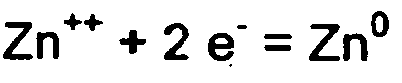
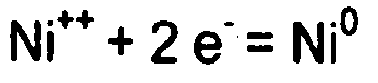
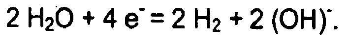
Fig. 3 zeigt den grundsätzlichen Badaufbau. In dem Behälter 1 ist die Anode 2 von der Kathode 3 durch eine Membran 4 getrennt. Dadurch wird der Anolyt 5, in dem die Anoden-Reaktion stattfindet, von dem den Katholyten darstellenden Zi-Ni-Elektrolyten 6 getrennt. Der Anolyt 5 besteht aus verdünnter Schwefelsäure; vorzugsweise enthält der Anolyt 5 100 g/l H2SO4. Durch diesen Aufbau diffundieren im wesentlichen lediglich Protonen bzw. Hydoxoniom-Ionen aus dem Anoden-Raum 5 in den Elektrolyten 6. Dies verhindert die inFig. 1 dargestellte oxidative Zerstörung der im Elektrolyten enthaltenden komplexbildenden Amine. Dadurch kann zum einen Chemie eingespart werden. Ferner werden keine oxidativen Abbauprodukte mehr gebildet, so dass in vorteilhafter Weise auch kein zu entsorgender Schlamm anfällt. Ferner wird dadurch eine geringere Ausschleppung erreicht, da der Elektrolyt kontinuierlich niedrig viskosend ist. - In diesem Bad stellt sich die Anoden-Reaktion (Membran) wie folgt dar:

- Die Kathoden-Reaktion ist wie folgt darzustellen:
- Die Membran ist vorzugsweise eine solche, wie sie in der
DE 198 34 353 beschrieben ist. Die diesbezügliche Offenbarung wird hiermit vollständig in die Beschreibung der vorliegenden Erfindung aufgenommen. Das Bad kann entweder wie inFig. 3 dargestellt eine Membran aufweisen. Ferner besteht die Möglichkeit, das Bad mit mehreren Membraneinheiten zu versehen. Diese bestehen vorzugsweise aus Kästen, die sowohl die Anode als auch die Membran enthalten. Zwischen die Membraneinheiten werden dann die Kathoden angeordnet. Dies hat den Vorteil, daß die Effizienz erhöht wird und verbrauchte oder beschädigte Membranen einfach und kostengünstig ausgetauscht werden können. -
Fig. 4a zeigt den Reinigungsprozess gemäß einer Ausführungsform. Der zu reinigende Elektrolyt 7 wird einem Verdampfer 8 zugeführt und aufkonzentriert. Der Verdampfer arbeitet vorzugsweise mit Vakuumverdampfung mit Wärmepumpenprinzip. Das Destillat wird wiederum dem Spülwasser zugeführt. Der aufkonzentrierte Elektrolyt 9 weist mehrere Phasen auf. Aufgrund des durch die Aufkonzentrierung ansteigenden Natronlauge-Gehalts ist das komplexbildende Amin im Elektrolyten nicht länger löslich. Dadurch bildet sich eine obere Phase 9a aus, die die Organik enthält. Diese Phase kann abdekantiert werden, wodurch die Organik vom übrigen Elektrolyten getrennt wird. Die verbleibende wässerige Phase 9b stellt den organikarmen Elektrolyten dar. Dieser enthält jedoch weiterhin Sulfate - bzw. die entsprechenden Salzkomponenten des Nickels - , die die Badzusammensetzung nachteilig beeinflussen. - Um auch diese zu entfernen und die Ausfällung von schwerlöslichen Sulfatsalzen zu verhindern, wird der organikarme Elektrolyt 9b in einen Kristallisator 10 geführt. Der Kristallisator 10 trennt durch Abkühlung auf ca. +-3° C den Elektrolyten 9b in zwei Teile. Durch Auskristallisation der Feststoffe entsteht eine Salzfracht, die einfach entsorgt werden kann. Zum anderen entsteht der regenerierte, gereinigte Elektrolyt 11. Dieser wird wiederum dem Katholyten des Bades zugeführt. Dadurch wird eine erhebliche Einsparung an Abwässern und Kosten erreicht und das Bad kann in einem kosteneffizienten und umweltbewußten Kreislaufprozeß geführt werden. Die entstehenden Monokonzentrate können Fachfirmen zur Entsorgung oder Wiederaufbereitung übergeben werden. Es versteht sich, daß durch die erfindungsgemäße Ausfällung nicht alle Sulfate aus dem Elektrolyten entfernt werden müssen, sondern lediglich eine Entfernung von überschüssigem Sulfat erfolgt, um die Konzentration unter eine kritische Grenze zu senken. Durch die Fällung kann beispielsweise die Konzentration von Sulfat von 60 - 65 g/l auf ca. 30 - 35 g/l gesenkt werden - je nach Wunsch -, so daß sie wieder in einem akzeptablen Bereich liegt.
-
Fig. 4b zeigt eine weitere Variante, in welcher auch die Spülwässer mittels Verdampfung aufkonzentriert werden. So werden beispielsweise bei der Zuführung von 1000 I Spülwasser 12 in den Verdampfer 8 100 I Konzentrat und 900 I Destillat gebildet. Das Konzentrat kann wiederum dem Katholyten des Bades zugeführt werden, das Destillat dem Spülwasser, wie dargestellt. -
Fig. 5 zeigt die Integration des erfindungsgemäßen Reinigungsverfahrens in das Gesamtsystem zum Betrieb des alkalischen Zink-Nickel-Bades. Wie dargestellt, erfolgt die Aufbereitung des Elektrolyten vorzugsweise diskontinuierlich. Die Reinigung des Elektrolyten durch Verdampfung und Kristallisation erfolgt vorzugsweise einmal pro Woche für einen Tag. - Die Führung des Badbetriebs soll anhand eines 20 000 I umfassenden Elektrolyten erläutert werden. Beim Betrieb des Bades erhöht sich das Volumen desselben durch den in
Fig. 2 dargestellten Volumenzuwachs nach vier Wochen bereits auf ca. 25 000 I. Die Sulfatkonzentration steigt durch die Zugabe der Nickellösung kontinuierlich auf ca. 60-65g/l im Elektrolyten an und muß gesenkt werden. - Die hinzugekommenen 5000 I werden um 3000 I eingeengt. 2000 I des gemäß dem erfindungsgemäßen Verfahren gereinigten Elektrolyten werden wiederum dem Bad zugeführt. Die restlichen ca. 3000 I Destillat werden dem Spülwasser zugeführt. Nach einer Woche werden von den 22 000 I wiederum 5000 I zum Aufreinigen entfernt. Die Differenz von 3000 I wird durch Zugabe von 3000 I frischen Elektrolyten ausgeglichen. Dadurch entsteht wiederum ein Gesamtvolumen von 20 000 I und 5000 I können wiederum dem erfindungsgemäßen Reinigungsprozess unterworfen werden.
-
Fig. 6 zeigt eine bevorzugte Aufreinigungsvariante, bei der der zu reinigende Elektrolyt in einen nicht dargestellten Verdampfer geführt wird und so lange eingedampft wird, bis sich sowohl die organische Phase ausbildet, als auch die Sulfate mit dem Gegenion der Lauge ausfallen. Nach der Eindampfung bilden sich drei Schichten. Zwei trübe, breiartige homogene Schichten aus Natriumsulfat und Organik 13a und 13b und der organik- und sulfatarme gereinigte Elektrolyt 13c. Diese Schichten können beispielsweise über ein Filtersystem 15 getrennt werden, indem durch eine Auslaßöffnung 14 zunächst der trübe Abfall 13b abgelassen wird. Sobald der klare Elektrolyt 13c kommt, wird dieser in einem Behälter 16 aufgefangen und zum Katholyten des Bades zurückgeführt. Sobald die zweite trübe Schicht 13a kommt, wird diese wiederum aufgefangen und entsorgt. Die Erfassung des Elektrolyten 13c kann beispielsweise durch einen Arbeiter erfolgen, oder durch eine Photodiode, die aufgrund des Trübungsgrades zwischen Abfall 13a und 13c und gereinigtem Elektrolyten 13c unterscheiden kann. Auch eine Bestimmung über die Messung der Leitfähigkeit wäre möglich.
Claims (14)
- Verfahren zum abwasserarmen Betrieb eines alkalischen Galvanikbades zum Aufbringen von Zink-Nickel-Überzügen auf ein Werkstück, wobei- das Bad (1) eine Anode (2) und eine Kathode (3) aufweist,- der Anolyt (5) von dem alkalischen Katholyten (6) durch eine Ionenaustauschermembran (4) getrennt ist und- der alkalische Katholyt (6) Zinkionen, Nickelionen und Komplexbildner aufweist,dadurch gekennzeichnet,- daß der Katholyt (6) von den sich durch den Betrieb des Bades anreichernden Komplexbildnern gereinigt wird, indem die zu reinigenden Katholytmengen (7) in einen Verdampfer geführt und aufkonzentriert werden, bis der Elektrolyt (7) eine organische Phase (9a, 13a, 13b) ausbildet,- daß der Elektrolyt (7, 9b) von Sulfaten befreit wird, indem diese ausgefällt werden.
- Verfahren nach Anspruch 1, dadurch gekennzeichnet, daß der Elektrolyt (7, 9b) in einen Kristallisator (10) geführt wird, in welchem er zur Ausfällung der Sulfate auf unter 10°C, vorzugsweise 5°C, abgekühlt wird.
- Verfahren nach Anspruch 1, dadurch gekennzeichnet, daß die Sulfate im Elektrolyten (7, 9b) in einem Verdampfer ausgefällt werden.
- Verfahren nach einem oder mehreren der Ansprüche 1 bis 3, dadurch gekennzeichnet, daß der gereinigte Elektrolyt (11, 13c) in den Katholyten (6) des Bades (1) zurückgeführt wird.
- Verfahren nach einem oder mehreren der Ansprüche 1 bis 4, dadurch gekennzeichnet, daß die abgetrennte organische Phase (9a) zu den Nickelkomponenten des Bades zurückgeführt wird.
- Verfahren nach einem oder mehreren der Ansprüche 1 bis 5, dadurch gekennzeichnet, daß das durch den Verdampfungsprozeß entstehende Destillat dem Spülwasser zugeführt wird.
- Verfahren nach einem oder mehreren der Ansprüche 1 bis 6, dadurch gekennzeichnet, daß der Anolyt (5) umgeflutet wird, wobei das Umfluten getaktet durchgeführt wird.
- Verfahren nach einem oder mehreren der Ansprüche 1 bis 7, dadurch gekennzeichnet, daß zumindest Teile des Katholyten (6) einmal wöchentlich aufbereitet werden.
- Verfahren nach einem oder mehreren der Ansprüche 1 bis 8, dadurch gekennzeichnet, daß die Sulfate durch ein Fällungsmittel ausgefällt werden.
- Verfahren nach einem oder mehreren der Ansprüche 1 bis 9, dadurch gekennzeichnet, daß das Spülwasser (12) in den Verdampfer (8) geführt und aufkonzentriert wird.
- Verfahren nach einem oder mehreren der Ansprüche 1 bis 10, dadurch gekennzeichnet, daß die zu reinigenden Katholytmengen (7) in einen Verdampfer (8) geführt werden und eingedampft werden, bis die Komplexbildner eine organische Phase ausbilden und die Sulfate mit dem Gegenion der Lauge als Salz ausfallen, wobei die organische Phase mit den Sulfatsalzen Schichten (13a, 13b) ausbildet, die von dem sulfat- und organikarmen Elektrolyten (13c) abgetrennt werden, wobei der gereinigte Elektrolyt (13c) zum Katholyten (6) zurückgeführt wird.
- System zur Pflege eines alkalischen Galvanikbades (1), wobei- das Bad (1) eine Anode (2) und eine Kathode (3) aufweist,- der Anolyt (5) von dem alkalischen Katholyten (6) durch eine Ionenaustauschermembran (4) getrennt ist und- der alkalische Katholyt (6) Zinkionen, Nickelionen und Komplexbildner aufweist,dadurch gekennzeichnet, daß- das System einen Verdampfer (8) aufweist, in dem die zu reinigenden Katholytmengen (7) aufkonzentriert werden, bis der Elektrolyt eine organische Phase (9a) ausbildet, die vom restlichen Elektrolyten (9b) abgetrennt werden kann,- das System eine Ausfällungseinheit (10) aufweist, in welcher der Elektrolyt (7, 9b) von Sulfaten befreit wird, indem diese als Salz ausgefällt werden.
- System nach Anspruch 12, dadurch gekennzeichnet, daß die Ausfällungseinheit ein Kristallisator (10) ist, der eine Kühleinheit aufweist.
- System nach Anspruch 12, dadurch gekennzeichnet, daß die Ausfällungseinheit ein Verdampfer ist.
Applications Claiming Priority (2)
| Application Number | Priority Date | Filing Date | Title |
|---|---|---|---|
| DE10355077A DE10355077A1 (de) | 2003-11-24 | 2003-11-24 | Verfahren zum abwasserarmen Betrieb eines alkalischen Zink-Nickel-Bades |
| DE10355077 | 2003-11-24 |
Publications (3)
| Publication Number | Publication Date |
|---|---|
| EP1533399A2 EP1533399A2 (de) | 2005-05-25 |
| EP1533399A3 EP1533399A3 (de) | 2009-01-07 |
| EP1533399B1 true EP1533399B1 (de) | 2011-02-16 |
Family
ID=34428886
Family Applications (1)
| Application Number | Title | Priority Date | Filing Date |
|---|---|---|---|
| EP04027712A Expired - Lifetime EP1533399B1 (de) | 2003-11-24 | 2004-11-23 | Verfahren zum abwasserarmen Betrieb eines alkalischen Zink-Nickel-Bades |
Country Status (4)
| Country | Link |
|---|---|
| EP (1) | EP1533399B1 (de) |
| AT (1) | ATE498716T1 (de) |
| DE (2) | DE10355077A1 (de) |
| ES (1) | ES2361306T3 (de) |
Families Citing this family (5)
| Publication number | Priority date | Publication date | Assignee | Title |
|---|---|---|---|---|
| DE102006030680A1 (de) * | 2006-07-04 | 2008-01-10 | Volkswagen Ag | Verfahren zur Verbesserung des Entschlammungs- und Ausfällungsverhaltens unerwünschter Stoffe, Ionen oder Schlämme in einem Prozessmedium beim Behandeln metallischer Werkstücke mit dem Prozessmedium in einem Prozessbad |
| DE102008058086B4 (de) * | 2008-11-18 | 2013-05-23 | Atotech Deutschland Gmbh | Verfahren und Vorrichtung zur Reinigung von galvanischen Bädern zur Abscheidung von Metallen |
| CN108866570A (zh) * | 2018-07-26 | 2018-11-23 | 江南大学 | 一种旋流电解回收电镀废水中络合镍的方法 |
| US11946152B2 (en) * | 2019-12-20 | 2024-04-02 | Atotech Deutschland GmbH & Co. KG | Method and system for depositing a zinc-nickel alloy on a substrate |
| EP4273303A1 (de) * | 2022-05-05 | 2023-11-08 | Atotech Deutschland GmbH & Co. KG | Verfahren zum abscheiden einer zink-nickel-legierung auf einem substrat, ein wässriges zink-nickel-abscheidungsbad, ein glanzmittel und verwendung davon |
Citations (1)
| Publication number | Priority date | Publication date | Assignee | Title |
|---|---|---|---|---|
| GB296989A (en) * | 1927-09-10 | 1929-12-06 | Wilhelm Georg Poetzsch | Process for eliminating excess sulphuric acid from chromium electrolytic baths |
Family Cites Families (5)
| Publication number | Priority date | Publication date | Assignee | Title |
|---|---|---|---|---|
| US3655337A (en) * | 1969-05-16 | 1972-04-11 | Kennecott Copper Corp | Process for desulfation of alkaline solutions |
| GB1497873A (en) * | 1975-01-18 | 1978-01-12 | Vyzk Ustav Chem Zarizeni | Process for the treatment of waste water containing inorganic salts from an installation for chemically preparing uranium ore |
| DE4441821C2 (de) * | 1994-11-24 | 2000-01-05 | Bosch Gmbh Robert | Verfahren zum Reinigen von Gegenständen mit anhaftenden Salzen |
| DE19710157A1 (de) * | 1997-03-12 | 1998-10-01 | Nukem Nuklear Gmbh | Verfahren und Vorrichtung zum Eindampfen sulfathaltiger Lösungen |
| DE19848467C5 (de) * | 1998-10-21 | 2006-04-27 | Walter Hillebrand Gmbh & Co. Kg Galvanotechnik | Alkalisches Zink-Nickelbad |
-
2003
- 2003-11-24 DE DE10355077A patent/DE10355077A1/de not_active Withdrawn
-
2004
- 2004-11-23 AT AT04027712T patent/ATE498716T1/de active
- 2004-11-23 EP EP04027712A patent/EP1533399B1/de not_active Expired - Lifetime
- 2004-11-23 ES ES04027712T patent/ES2361306T3/es not_active Expired - Lifetime
- 2004-11-23 DE DE502004012189T patent/DE502004012189D1/de not_active Expired - Lifetime
Patent Citations (1)
| Publication number | Priority date | Publication date | Assignee | Title |
|---|---|---|---|---|
| GB296989A (en) * | 1927-09-10 | 1929-12-06 | Wilhelm Georg Poetzsch | Process for eliminating excess sulphuric acid from chromium electrolytic baths |
Also Published As
| Publication number | Publication date |
|---|---|
| EP1533399A3 (de) | 2009-01-07 |
| DE502004012189D1 (de) | 2011-03-31 |
| ES2361306T3 (es) | 2011-06-15 |
| ATE498716T1 (de) | 2011-03-15 |
| DE10355077A1 (de) | 2005-06-09 |
| EP1533399A2 (de) | 2005-05-25 |
Similar Documents
| Publication | Publication Date | Title |
|---|---|---|
| DE3885682T2 (de) | Verfahren zum Galvanisieren von Metallen. | |
| EP1102875B1 (de) | Alkalisches zink-nickelbad | |
| DE69115458T2 (de) | Elektrolysezelle und Verfahren zu ihrem Betrieb | |
| EP0158910B1 (de) | Verfahren zur Rückgewinnung von Kupfer aus einer ammoniakalischen Kupfer-Ätzlösung und Rekonditionierung derselben | |
| WO2004059045A2 (de) | Anode zur galvanisierung | |
| DE4023444A1 (de) | Cyanid-freies verfahren zur herstellung eines galvanischen kupferueberzuges | |
| EP1533399B1 (de) | Verfahren zum abwasserarmen Betrieb eines alkalischen Zink-Nickel-Bades | |
| DE69117927T2 (de) | Verfahren zum Behandeln eines geschmolzenen Salzbades | |
| DE2721994A1 (de) | Verfahren zur aufarbeitung waessriger rueckstaende von metallisierungsbaedern | |
| WO2012031753A1 (de) | Anode sowie deren verwendung in einem alkalischen galvanikbad | |
| EP1831435B1 (de) | Verfahren für den kontinuierlichen betrieb von sauren oder alkalischen zink- oder zinklegierungsbädern | |
| DE69203600T2 (de) | Elektrode für eine elektrolytische zelle, deren gebrauch und verfahren. | |
| DE60111558T2 (de) | Verfahren und vorrichtung zur abtrennung und zerstörung von gelöstem nitrat | |
| DE60104361T2 (de) | Verfahren zur Metalloberflächenbehandlung | |
| EP0240589B1 (de) | Verfahren zur Regenerierung eines stromlosen Verkupferungsbades und Vorrichtung zur Durchführung desselben | |
| DE4405741C1 (de) | Verfahren zur elektrolytischen Abscheidung von Metallen aus Elektrolyten mit Prozeßorganik | |
| EP1080252B1 (de) | Verfahren zur galvanischen verkupferung von substraten | |
| EP1006213B1 (de) | Verfahren zum Regenerieren einer Prozesslösung | |
| DE2940741C2 (de) | ||
| DE3312241C2 (de) | ||
| WO2010078866A2 (de) | Verfahren und vorrichtung zum regenerieren von peroxodisulfat-beizlösungen | |
| DE2057606A1 (de) | Verfahren und Einrichtung zur Rueckgewinnung von Nickel und/oder von anderen der Eisengruppe des periodischen Systems angehoerenden,vorzugsweise hoeherwertigen Metallen | |
| DE4229917C1 (en) | Electrolytic bath for meter coating - has sec. anode contg. alkaline or ammonium soln. with acid added to electrolyte to compensate for pH rise | |
| DE3206538C2 (de) | Verfahren zur elektrolytischen Regenerierung von verbrauchter Schwefelsäure-Beizflüssigkeit | |
| DE3310730A1 (de) | Verfahren zum entfernen ueberschuessiger metall-ionen aus sauren chloridhaltigen galvanischen baeder |
Legal Events
| Date | Code | Title | Description |
|---|---|---|---|
| PUAI | Public reference made under article 153(3) epc to a published international application that has entered the european phase |
Free format text: ORIGINAL CODE: 0009012 |
|
| AK | Designated contracting states |
Kind code of ref document: A2 Designated state(s): AT BE BG CH CY CZ DE DK EE ES FI FR GB GR HU IE IS IT LI LU MC NL PL PT RO SE SI SK TR |
|
| AX | Request for extension of the european patent |
Extension state: AL HR LT LV MK YU |
|
| RIN1 | Information on inventor provided before grant (corrected) |
Inventor name: HILLEBRAND, ERNST-WALTER Inventor name: MORGENSTERN, KARL Inventor name: KLOS, KLAUS-PETER, DR. |
|
| PUAL | Search report despatched |
Free format text: ORIGINAL CODE: 0009013 |
|
| AK | Designated contracting states |
Kind code of ref document: A3 Designated state(s): AT BE BG CH CY CZ DE DK EE ES FI FR GB GR HU IE IS IT LI LU MC NL PL PT RO SE SI SK TR |
|
| AX | Request for extension of the european patent |
Extension state: AL HR LT LV MK YU |
|
| RIC1 | Information provided on ipc code assigned before grant |
Ipc: C02F 1/04 20060101ALI20081128BHEP Ipc: C25D 3/56 20060101AFI20050329BHEP Ipc: C25D 21/18 20060101ALI20081128BHEP |
|
| 17P | Request for examination filed |
Effective date: 20090703 |
|
| AKX | Designation fees paid |
Designated state(s): AT BE BG CH CY CZ DE DK EE ES FI FR GB GR HU IE IS IT LI LU MC NL PL PT RO SE SI SK TR |
|
| 17Q | First examination report despatched |
Effective date: 20090907 |
|
| RTI1 | Title (correction) |
Free format text: PROCESS FOR LOW WASTE WATER OPERATION OF ALKALINE ZINC-NICKEL BATH |
|
| GRAP | Despatch of communication of intention to grant a patent |
Free format text: ORIGINAL CODE: EPIDOSNIGR1 |
|
| GRAS | Grant fee paid |
Free format text: ORIGINAL CODE: EPIDOSNIGR3 |
|
| GRAA | (expected) grant |
Free format text: ORIGINAL CODE: 0009210 |
|
| AK | Designated contracting states |
Kind code of ref document: B1 Designated state(s): AT BE BG CH CY CZ DE DK EE ES FI FR GB GR HU IE IS IT LI LU MC NL PL PT RO SE SI SK TR |
|
| REG | Reference to a national code |
Ref country code: GB Ref legal event code: FG4D Free format text: NOT ENGLISH |
|
| REG | Reference to a national code |
Ref country code: CH Ref legal event code: EP |
|
| REG | Reference to a national code |
Ref country code: IE Ref legal event code: FG4D Free format text: LANGUAGE OF EP DOCUMENT: GERMAN |
|
| REF | Corresponds to: |
Ref document number: 502004012189 Country of ref document: DE Date of ref document: 20110331 Kind code of ref document: P |
|
| REG | Reference to a national code |
Ref country code: DE Ref legal event code: R096 Ref document number: 502004012189 Country of ref document: DE Effective date: 20110331 |
|
| REG | Reference to a national code |
Ref country code: NL Ref legal event code: VDEP Effective date: 20110216 Ref country code: ES Ref legal event code: FG2A Ref document number: 2361306 Country of ref document: ES Kind code of ref document: T3 Effective date: 20110615 |
|
| PG25 | Lapsed in a contracting state [announced via postgrant information from national office to epo] |
Ref country code: SE Free format text: LAPSE BECAUSE OF FAILURE TO SUBMIT A TRANSLATION OF THE DESCRIPTION OR TO PAY THE FEE WITHIN THE PRESCRIBED TIME-LIMIT Effective date: 20110216 Ref country code: PT Free format text: LAPSE BECAUSE OF FAILURE TO SUBMIT A TRANSLATION OF THE DESCRIPTION OR TO PAY THE FEE WITHIN THE PRESCRIBED TIME-LIMIT Effective date: 20110616 Ref country code: GR Free format text: LAPSE BECAUSE OF FAILURE TO SUBMIT A TRANSLATION OF THE DESCRIPTION OR TO PAY THE FEE WITHIN THE PRESCRIBED TIME-LIMIT Effective date: 20110517 |
|
| REG | Reference to a national code |
Ref country code: SK Ref legal event code: T3 Ref document number: E 9343 Country of ref document: SK |
|
| PG25 | Lapsed in a contracting state [announced via postgrant information from national office to epo] |
Ref country code: FI Free format text: LAPSE BECAUSE OF FAILURE TO SUBMIT A TRANSLATION OF THE DESCRIPTION OR TO PAY THE FEE WITHIN THE PRESCRIBED TIME-LIMIT Effective date: 20110216 Ref country code: BG Free format text: LAPSE BECAUSE OF FAILURE TO SUBMIT A TRANSLATION OF THE DESCRIPTION OR TO PAY THE FEE WITHIN THE PRESCRIBED TIME-LIMIT Effective date: 20110516 Ref country code: PL Free format text: LAPSE BECAUSE OF FAILURE TO SUBMIT A TRANSLATION OF THE DESCRIPTION OR TO PAY THE FEE WITHIN THE PRESCRIBED TIME-LIMIT Effective date: 20110216 Ref country code: NL Free format text: LAPSE BECAUSE OF FAILURE TO SUBMIT A TRANSLATION OF THE DESCRIPTION OR TO PAY THE FEE WITHIN THE PRESCRIBED TIME-LIMIT Effective date: 20110216 Ref country code: SI Free format text: LAPSE BECAUSE OF FAILURE TO SUBMIT A TRANSLATION OF THE DESCRIPTION OR TO PAY THE FEE WITHIN THE PRESCRIBED TIME-LIMIT Effective date: 20110216 Ref country code: CY Free format text: LAPSE BECAUSE OF FAILURE TO SUBMIT A TRANSLATION OF THE DESCRIPTION OR TO PAY THE FEE WITHIN THE PRESCRIBED TIME-LIMIT Effective date: 20110216 |
|
| REG | Reference to a national code |
Ref country code: IE Ref legal event code: FD4D |
|
| PG25 | Lapsed in a contracting state [announced via postgrant information from national office to epo] |
Ref country code: DK Free format text: LAPSE BECAUSE OF FAILURE TO SUBMIT A TRANSLATION OF THE DESCRIPTION OR TO PAY THE FEE WITHIN THE PRESCRIBED TIME-LIMIT Effective date: 20110216 Ref country code: IE Free format text: LAPSE BECAUSE OF FAILURE TO SUBMIT A TRANSLATION OF THE DESCRIPTION OR TO PAY THE FEE WITHIN THE PRESCRIBED TIME-LIMIT Effective date: 20110216 Ref country code: EE Free format text: LAPSE BECAUSE OF FAILURE TO SUBMIT A TRANSLATION OF THE DESCRIPTION OR TO PAY THE FEE WITHIN THE PRESCRIBED TIME-LIMIT Effective date: 20110216 |
|
| PG25 | Lapsed in a contracting state [announced via postgrant information from national office to epo] |
Ref country code: RO Free format text: LAPSE BECAUSE OF FAILURE TO SUBMIT A TRANSLATION OF THE DESCRIPTION OR TO PAY THE FEE WITHIN THE PRESCRIBED TIME-LIMIT Effective date: 20110216 |
|
| PLBE | No opposition filed within time limit |
Free format text: ORIGINAL CODE: 0009261 |
|
| STAA | Information on the status of an ep patent application or granted ep patent |
Free format text: STATUS: NO OPPOSITION FILED WITHIN TIME LIMIT |
|
| 26N | No opposition filed |
Effective date: 20111117 |
|
| REG | Reference to a national code |
Ref country code: DE Ref legal event code: R097 Ref document number: 502004012189 Country of ref document: DE Effective date: 20111117 |
|
| BERE | Be: lapsed |
Owner name: WALTER HILLEBRAND G.M.B.H. & CO. GALVANOTECHNIK Effective date: 20111130 |
|
| PG25 | Lapsed in a contracting state [announced via postgrant information from national office to epo] |
Ref country code: MC Free format text: LAPSE BECAUSE OF NON-PAYMENT OF DUE FEES Effective date: 20111130 |
|
| REG | Reference to a national code |
Ref country code: CH Ref legal event code: PL |
|
| GBPC | Gb: european patent ceased through non-payment of renewal fee |
Effective date: 20111123 |
|
| PG25 | Lapsed in a contracting state [announced via postgrant information from national office to epo] |
Ref country code: SK Free format text: LAPSE BECAUSE OF NON-PAYMENT OF DUE FEES Effective date: 20111123 Ref country code: CZ Free format text: LAPSE BECAUSE OF NON-PAYMENT OF DUE FEES Effective date: 20111123 Ref country code: LI Free format text: LAPSE BECAUSE OF NON-PAYMENT OF DUE FEES Effective date: 20111130 Ref country code: CH Free format text: LAPSE BECAUSE OF NON-PAYMENT OF DUE FEES Effective date: 20111130 |
|
| REG | Reference to a national code |
Ref country code: SK Ref legal event code: MM4A Ref document number: E 9343 Country of ref document: SK Effective date: 20111123 |
|
| REG | Reference to a national code |
Ref country code: FR Ref legal event code: ST Effective date: 20120731 |
|
| PG25 | Lapsed in a contracting state [announced via postgrant information from national office to epo] |
Ref country code: BE Free format text: LAPSE BECAUSE OF NON-PAYMENT OF DUE FEES Effective date: 20111130 |
|
| PG25 | Lapsed in a contracting state [announced via postgrant information from national office to epo] |
Ref country code: GB Free format text: LAPSE BECAUSE OF NON-PAYMENT OF DUE FEES Effective date: 20111123 |
|
| PG25 | Lapsed in a contracting state [announced via postgrant information from national office to epo] |
Ref country code: FR Free format text: LAPSE BECAUSE OF NON-PAYMENT OF DUE FEES Effective date: 20111130 |
|
| REG | Reference to a national code |
Ref country code: AT Ref legal event code: MM01 Ref document number: 498716 Country of ref document: AT Kind code of ref document: T Effective date: 20111123 |
|
| PG25 | Lapsed in a contracting state [announced via postgrant information from national office to epo] |
Ref country code: AT Free format text: LAPSE BECAUSE OF NON-PAYMENT OF DUE FEES Effective date: 20111123 |
|
| PG25 | Lapsed in a contracting state [announced via postgrant information from national office to epo] |
Ref country code: LU Free format text: LAPSE BECAUSE OF NON-PAYMENT OF DUE FEES Effective date: 20111123 |
|
| REG | Reference to a national code |
Ref country code: ES Ref legal event code: FD2A Effective date: 20130603 |
|
| PG25 | Lapsed in a contracting state [announced via postgrant information from national office to epo] |
Ref country code: IS Free format text: LAPSE BECAUSE OF FAILURE TO SUBMIT A TRANSLATION OF THE DESCRIPTION OR TO PAY THE FEE WITHIN THE PRESCRIBED TIME-LIMIT Effective date: 20110216 Ref country code: ES Free format text: LAPSE BECAUSE OF NON-PAYMENT OF DUE FEES Effective date: 20111124 |
|
| PG25 | Lapsed in a contracting state [announced via postgrant information from national office to epo] |
Ref country code: IT Free format text: LAPSE BECAUSE OF NON-PAYMENT OF DUE FEES Effective date: 20121123 |
|
| PG25 | Lapsed in a contracting state [announced via postgrant information from national office to epo] |
Ref country code: TR Free format text: LAPSE BECAUSE OF FAILURE TO SUBMIT A TRANSLATION OF THE DESCRIPTION OR TO PAY THE FEE WITHIN THE PRESCRIBED TIME-LIMIT Effective date: 20110216 |
|
| PG25 | Lapsed in a contracting state [announced via postgrant information from national office to epo] |
Ref country code: HU Free format text: LAPSE BECAUSE OF FAILURE TO SUBMIT A TRANSLATION OF THE DESCRIPTION OR TO PAY THE FEE WITHIN THE PRESCRIBED TIME-LIMIT Effective date: 20110216 |
|
| PGFP | Annual fee paid to national office [announced via postgrant information from national office to epo] |
Ref country code: DE Payment date: 20181220 Year of fee payment: 15 |
|
| REG | Reference to a national code |
Ref country code: DE Ref legal event code: R119 Ref document number: 502004012189 Country of ref document: DE |
|
| PG25 | Lapsed in a contracting state [announced via postgrant information from national office to epo] |
Ref country code: DE Free format text: LAPSE BECAUSE OF NON-PAYMENT OF DUE FEES Effective date: 20200603 |