EP1531077A2 - Unité de pompe et véhicule de travail - Google Patents
Unité de pompe et véhicule de travail Download PDFInfo
- Publication number
- EP1531077A2 EP1531077A2 EP04025195A EP04025195A EP1531077A2 EP 1531077 A2 EP1531077 A2 EP 1531077A2 EP 04025195 A EP04025195 A EP 04025195A EP 04025195 A EP04025195 A EP 04025195A EP 1531077 A2 EP1531077 A2 EP 1531077A2
- Authority
- EP
- European Patent Office
- Prior art keywords
- pump
- shaft
- pto
- housing
- input shaft
- Prior art date
- Legal status (The legal status is an assumption and is not a legal conclusion. Google has not performed a legal analysis and makes no representation as to the accuracy of the status listed.)
- Granted
Links
Images


Classifications
-
- B—PERFORMING OPERATIONS; TRANSPORTING
- B60—VEHICLES IN GENERAL
- B60K—ARRANGEMENT OR MOUNTING OF PROPULSION UNITS OR OF TRANSMISSIONS IN VEHICLES; ARRANGEMENT OR MOUNTING OF PLURAL DIVERSE PRIME-MOVERS IN VEHICLES; AUXILIARY DRIVES FOR VEHICLES; INSTRUMENTATION OR DASHBOARDS FOR VEHICLES; ARRANGEMENTS IN CONNECTION WITH COOLING, AIR INTAKE, GAS EXHAUST OR FUEL SUPPLY OF PROPULSION UNITS IN VEHICLES
- B60K17/00—Arrangement or mounting of transmissions in vehicles
- B60K17/28—Arrangement or mounting of transmissions in vehicles characterised by arrangement, location, or type of power take-off
-
- B—PERFORMING OPERATIONS; TRANSPORTING
- B60—VEHICLES IN GENERAL
- B60K—ARRANGEMENT OR MOUNTING OF PROPULSION UNITS OR OF TRANSMISSIONS IN VEHICLES; ARRANGEMENT OR MOUNTING OF PLURAL DIVERSE PRIME-MOVERS IN VEHICLES; AUXILIARY DRIVES FOR VEHICLES; INSTRUMENTATION OR DASHBOARDS FOR VEHICLES; ARRANGEMENTS IN CONNECTION WITH COOLING, AIR INTAKE, GAS EXHAUST OR FUEL SUPPLY OF PROPULSION UNITS IN VEHICLES
- B60K17/00—Arrangement or mounting of transmissions in vehicles
- B60K17/04—Arrangement or mounting of transmissions in vehicles characterised by arrangement, location, or kind of gearing
- B60K17/10—Arrangement or mounting of transmissions in vehicles characterised by arrangement, location, or kind of gearing of fluid gearing
Definitions
- the present invention relates to a pump unit used as a hydraulic source for a pair of hydraulic motor units allocated and arranged on both sides in a width direction of a vehicle so as to drive a pair of left and right driving axles, and to a working vehicle equipped with the pump unit.
- a free space at a central portion in a width direction of the vehicle without enlarging the entire vehicle size. That is, by forming the free space at the central portion in the width direction of the vehicle, the free space can be used as an installation space for a mid-mount mower, used as a center discharger path and, further, used as an installation space for a mower lifting cylinder, thus enhancing the degree of freedom of design of the working vehicle.
- a working vehicle comprising a hydraulic pump unit operatively connected to a driving source, and a pair of hydraulic motor units allocated and arranged on both sides in a width direction of a vehicle so as to drive a pair of right and left driving axles, wherein the hydraulic pump unit and the pair of hydraulic motor units are fluidly connected to each other via a conduit.
- the conventional working vehicle having the above configuration is effective in preventing a traveling-system transmission mechanism to be interposed between the pair of driving axles, but is ineffective with regard to the following points.
- a PTO-system transmission mechanism for transmitting power from the driving source to a working machine must be arranged in addition to the traveling-system transmission mechanism for transmitting power from the driving source to the pair of driving axles.
- the traveling-system transmission mechanism not only the traveling-system transmission mechanism, but the PTO-system transmission mechanism must also be considered in order to secure a free space at the central portion in the width direction of the vehicle.
- the conventional working vehicle prevents the traveling-system transmission mechanism from being positioned at the central portion in the width direction of the vehicle due to the above configuration, but the PTO-system transmission mechanism is not taken into consideration.
- the present invention has been made in view of the above conventional art, and it is an object of the present invention to provide a pump unit applicable to a working vehicle equipped with a working machine.
- the pump unit forms a traveling-system transmission mechanism in cooperation with a pair of hydraulic motor units allocated and arranged on both sides in a width direction of a vehicle and, also, forms a PTO-system transmission mechanism for outputting rotational power toward the working machine.
- the pump unit can prevent both the traveling-system transmission mechanism and the PTO-system transmission mechanism from being positioned at a central portion in the width direction of the vehicle as much as possible.
- a pump unit for transmitting mechanical power from a driving source through fluid power to first and second hydraulic motor units allocated and arranged on both sides in a width direction of a vehicle so as to be output to a pair of right and left driving wheels.
- the pump unit includes an input shaft operatively connected to the driving source; first and second pump shafts operatively connected to the input shaft; first and second hydraulic pump bodies driven by the first and second pump shafts, respectively, and fluidly connected to the first and second hydraulic motor units, respectively; a housing for supporting the input shaft, the first pump shaft and the second pump shaft and, also, containing therein the first and second hydraulic pump bodies; and a PTO device contained in the housing,
- the PTO device has a PTO shaft supported by the housing so as to be substantially parallel to the input shaft.
- the housing is configured to support the input shaft and the PTO shaft so that the input shaft is arranged at substantially a central portion in the width direction of the vehicle and the PTO shaft is displaced to and arranged on one side in the width direction of the vehicle with said input shaft as a reference, when the housing is mounted in the working vehicle.
- the traveling-system transmission mechanism is formed in such a manner that the pump unit is fluidly connected to the first and second hydraulic motor units allocated and arranged on both sides in the width direction of the vehicle. It is accordingly possible to effectively prevent the traveling-system transmission mechanism from being positioned at the central portion of the body frame in the width direction of the vehicle.
- the pump unit supports the input shaft operatively connected to the driving source and the PTO shaft for outputting power toward the working machine in a state where the input shaft and the PTO shaft are displaced each other in the width direction of the vehicle. Therefore, the pump unit is directly or indirectly arranged on the body frame in such a manner that the input shaft is positioned at substantially the central portion in the width direction of the body frame, so that the PTO shaft can be displaced to one side from substantially the central portion in the width direction of the body frame. With this configuration, it is possible to effectively prevent the PTO-system transmission mechanism from being positioned at the central portion in the width direction of the body frame.
- the present invention it is possible to effectively prevent both the traveling-system transmission mechanism and the PTO-system transmission mechanism from being positioned at the central portion in the width direction of the body frame. Accordingly, a free space can be secured at the central portion in the width direction of the body frame, thereby improving the degree of freedom in design of the vehicle.
- At least one of the input shaft, the first pump shaft and the second pump shaft may have an outward end extended outwardly from the housing.
- the outward end supports a member to be driven
- At least two of the input shaft, the first pump shaft and the second pump shaft may have outward ends extended outwardly from said housing.
- the outward ends support a cooling fan and a charge pump, respectively.
- the housing is configured so as to support the first and second pump shafts between the input shaft and the PTO shaft with respect to the width direction of the vehicle.
- the input shaft and the first pump shaft may be arranged concentrically.
- the housing is configured so as to support the second pump shaft between the input shaft and the PTO shaft with respect to the width direction of the vehicle.
- the input shaft and the first pump shaft are integrally formed with a single member
- the input shaft, the first pump shaft, the second pump shaft and the PTO shaft may be arranged along the longitudinal direction of the vehicle.
- each of the first and second pump bodies has a cylinder block rotatably driven by the corresponding pump shaft, a piston provided in a slidable manner in an axial line direction of the pump and in a non-rotatable manner relative to the cylinder block about the axial line of the pump, and an output adjusting member for changing a sliding range in the axial line direction of the pump of the piston.
- the housing includes a housing body having a pump accommodating section which contains therein the first and second hydraulic pump bodies and communicates outwardly via a first opening into which the first and second hydraulic pump bodies can be inserted, and a center section formed with a part of a hydraulic circuit for fluidly connecting the first and second hydraulic pump bodies to the first and second hydraulic motor units, respectively.
- the first opening is liquid-tightly closed by the center section.
- the housing body may have a PTO accommodating section which contains therein the PTO device and communicates outwardly via a second opening into which the PTO device can be inserted.
- the second opening is positioned on the opposite side in the longitudinal direction of the vehicle to the first opening.
- the housing further has a lid member connected to the housing body so as to liquid-tightly close the second opening.
- the PTO device may include a hydraulic PTO clutch for selectively engaging/releasing the power transmission from the input shaft to the PTO shaft.
- the PTO clutch is configured so as to switch between the engaging state and the releasing state by supply/stop of a pressure oil to a clutch operating oil path perforated in the PTO shaft.
- the PTO shaft is supported by the housing body and the lid member. The support portion of the PTO shaft by the lid member is provided with a seal case part for introducing the pressure oil to the clutch operating oil path.
- a working vehicle including a body frame; a driving source supported by the body frame; a pair of driving wheels supported by the body frame; a single pump unit operatively connected to the driving source and having a PTO device including a PTO shaft; a pair of hydraulic motor units fluidly connected to the pump unit, and allocated and arranged in a width direction of the vehicle so as to drive the pair of driving wheels; and a working machine operatively connected to the PTO device in the pump unit.
- the pump unit further has an input shaft operatively connected to the driving source; first and second pump shafts operatively connected to the input shaft; first and second hydraulic pump bodies driven by the first and second pump shafts, respectively, and fluidly connected to the first and second hydraulic motor units, respectively; and a housing for supporting the input shaft, the first pump shaft, the second pump shaft and the PTO shaft and, also, containing therein the first hydraulic pump body, the second hydraulic pump body and the PTO device.
- the input shaft and the PTO shaft are allocated and supported at both sides in the width direction of the housing of the vehicle.
- the housing is directly or indirectly supported by the body frame so that the input shaft is positioned at substantially a central portion in the width direction of the body frame.
- the driving source is supported to the body frame so as to vibrate freely, and the housing is integrally connected to the driving source in a free state with respect to the body frame.
- the pump unit configures a traveling-system transmission mechanism in cooperation with a hydraulic motor unit fluidly connected via a hydraulic circuit and driven by an action of a pressure oil in the hydraulic circuit and, also, configures a PTO-system transmission mechanism for outputting power to a working machine.
- Figs. 1(a) and 1(b) show a side view and a plan view of the working vehicle 100 to which the pump unit 1 according to this embodiment is applied.
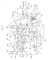
- Fig. 2 shows a hydraulic circuit diagram of the pump unit 1.
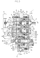
- Fig. 3 shows a transverse sectional plan view of the pump unit 1 according to this embodiment.
- the working vehicle 100 is of a mid-mount type in which a ground working machine 140 is arranged between a front wheel (caster 130 in this embodiment shown in the figure) and a rear wheel (driving wheel 120 in this embodiment shown in the figure) with respect to a longitudinal direction of the vehicle.
- a ground working machine 140 is arranged between a front wheel (caster 130 in this embodiment shown in the figure) and a rear wheel (driving wheel 120 in this embodiment shown in the figure) with respect to a longitudinal direction of the vehicle.
- the working vehicle 100 comprises a body frame 110, a pair of right and left driving wheels (rear wheels in this embodiment) 120 supported by the body frame 110, a pair of right and left casters 130 supported by the body frame 110 so as to be arranged on one side (forward side in this embodiment) in the longitudinal direction of the vehicle of the driving wheels 120, a ground working machine (mower in this embodiment) 140 supported by the body frame 110 so as to be positioned between the driving wheels 120 and the casters 130, a driving source 150 supported by the body frame 110 so as to be positioned on the opposite side (backward side in this embodiment) of the ground working machine 140 with the driving wheels 120 along the longitudinal direction of the vehicle, first and second hydraulic motor units 160a, 160b operatively connected at their motor shafts to the pair of right and left driving wheels 120, respectively, and the pump unit 1 according to this embodiment.
- first and second hydraulic motor units 160a, 160b operatively connected at their motor shafts to the pair of right and left driving wheels 120, respectively, and the pump unit 1 according to this
- the first and second hydraulic motor units 160a, 160b are allocated and arranged on the left and right side along the width direction of the vehicle.
- the working vehicle 100 prevents the traveling-system transmission mechanism from being positioned at the central portion in the width direction of the vehicle, and secures a free space at the central portion in the width direction of the body frame 110.
- Figs. 4 and 5 show cross sectional views taken along lines IV-IV and line V-V in Fig. 3, respectively.
- the pump unit 1 is configured so as to be fluidly connected to the hydraulic motors 160a, 160b arranged spaced apart from the pump unit 1 via the hydraulic circuit so that the hydraulic motors 160a, 160b output the power, which is input from the driving source 150 to the pump unit 1 and transmitted to the hydraulic motor units 160a, 160b via the action of the oil pressure, thereby driving the driving wheels 120. That is, the pump unit 1 forms the traveling-system transmission mechanism serving as a main transmission path together with the hydraulic motor units 160a, 160b.
- the pump unit 1 is configured so as to branch the power from the driving source 150 and extract the driving power of the ground working machine 140. That is, the pump unit 1 also forms a part of the PTO-system transmission mechanism.
- the pump unit 1 comprises an input shaft 10 operatively connected to the driving source 150, first and second pump shafts 20a, 20b operatively connected to the input shaft 10, first and second hydraulic pump bodies 30a, 30b driven by the first and second pump shafts 20a, 20b, respectively, a housing 40 for supporting the input shaft 10, the first pump shaft 20a and the second pump shaft 20b and, also, containing therein the first and second hydraulic pump bodies 30a, 30b, and a PTO device 50 contained in the housing 40.
- the first hydraulic pump body 30a and the second hydraulic pump body 30b are fluidly connected to the first hydraulic motor unit 160a and the second hydraulic motor unit 160b, respectively, via a hydraulic circuit (a pair of first hydraulic lines 501a and a pair of second hydraulic lines 501b in this embodiment).
- At least one of the first hydraulic pump body 30a and the first hydraulic motor unit 160a fluidly connected to each other is of a variable displacement type in which suction/discharge rates change by the operation of an output adjusting member, and a non-stepwise speed change output is obtained from the motor shaft of the first hydraulic motor unit 160a by controlling a slanting position of the output adjusting member.
- At least one of the second hydraulic pump body 30b and the second hydraulic motor unit 160b is of a variable displacement type in which suction/discharge rates changes by the operation of the output adjusting member, and a non-stepwise speed change output is obtained from the motor shaft of the second hydraulic motor unit 160b by controlling the slanting position of the output adjusting member.
- each of the hydraulic pump bodies 30a, 30b is of a variable displacement type and each of the hydraulic motor units 160a, 160b is of a fixed displacement type.
- the input shaft 10 is supported by the housing 40 so that an upstream end in the transmitting direction (rear end in this embodiment) extends outwardly (backward in this embodiment) from the housing 40 along the longitudinal direction of the vehicle, and is operatively connected to the driving source 150 via a flywheel 155.
- the flywheel 155 may be provided with a damper 156 (see Fig. 1).
- a damper 156 see Fig. 1
- power transmission can be performed from the driving source 150 to the input shaft 10 while suppressing the angular speed variation of the output shaft of the driving source 150. It is therefore possible to improve the durability of the hydraulic pump bodies 30a, 30b. Further, since the pulsation of the oil ejected from the hydraulic pump bodies 30a, 30b is suppressed, the durability of the hydraulic motor units 160a, 160b subjected to the oil pressure is also improved and the noise/vibration can be reduced.
- the input shaft 10 is integrally formed with the first pump shaft 20a by a single member.
- the input shaft 10 and the first pump shaft 20a are defined as a single shaft 15.
- the first pump shaft 20a is supported by the housing 40 along the longitudinal direction of the vehicle.
- the first pump shaft 20a may be configured to have a first end which extends outwardly (forward in this embodiment) from the housing 40 to drive a member to be driven by the first end.
- a cooling fan 70 serving as the member to be driven is provided.
- the first pump shaft 20a is integrally formed with the input shaft 10 and is defined as the single shaft 15.
- the upstream side in the transmitting direction of the single shaft 15 configures the input shaft 10
- the downstream side of the transmitting direction configures the first pump shaft 20a.
- the single shaft 15 is extended outwardly from the housing 40 so that its rear end and the front end form a connection portion to the driving source 150 and a support portion of the cooling fan 70, respectively.
- the second pump shaft 20b is also supported by the housing 40 along the longitudinal direction of the vehicle.
- the second pump shaft 20b may be configured to have a first end which extends outwardly from the housing 40 to drive a member to be driven by the first end.
- a charge pump 80 serving as the member to be driven is provided.
- the charge pump 80 includes a charge pump body 81 driven by the outwardly extended end of the second pump shaft 20b, and a charge pump case 82 for surrounding the charge pump body 81.
- the first and second pump shafts 20a, 20b are operatively connected to the input shaft 10, as described above.
- the pump unit 1 includes a power transmission mechanism 75 for transmitting the rotational power of the input shaft 10 to the first and second pump shafts 20a, 20b.
- the first pump shaft 20a is integrally formed with the input shaft 10 by the single shaft 15, as described above.
- the pump unit 1 comprises, as the power transmission mechanism 75, a driving gear 76 supported in a non-rotatable manner relative to the single shaft 15, and a driven gear 77 supported in a non-rotatable manner relative to the second pump shaft 20b so as to mesh with the driving gear 76.
- the driving gear 76 and the driven gear 77 have a same pitch diameter; thus, the first pump shaft 20a (single shaft 15) and the second pump shaft 20b rotate in synchronization.
- the input shaft 10 is integrally formed with the first pump shaft 20a; however, the input shaft 10 and the first pump shaft 20a may of course be separately provided.
- the first hydraulic pump body 30a includes a cylinder block 31a which rotates about an axis line of the first pump shaft 20a along with the rotation of the first pump shaft 20a, a piston unit 32a which rotates about the axis line of the first pump shaft 20a along with the rotation of the cylinder block 31a and, also, is slidable in the axis line direction of the first pump shaft 20a with respect to the cylinder block 31a, and an output adjusting member 33a (combination of movable swash plate 34a and an operating shaft 35a) which regulates the stroke length of the piston unit depending on the slanting position and changes oil suction/discharge rates by the cylinder block 31a.
- the second hydraulic pump body 30b has substantially the same configuration as the first hydraulic pump body 30a except that the second hydraulic pump body 30b is driven by the second pump shaft 20b. Therefore, in the figure, similar reference characters with a different subscript are denoted for the members same as or corresponding to those of the first hydraulic pump body 30a, and the description of the second hydraulic pump body 30b will not be given herein.
- each of the hydraulic pump bodies 30a, 30b is of an axial piston type, but may also be of a radial piston type.
- the PTO device 50 has a PTO shaft 51 for outputting the power toward the ground working machine 140.
- the PTO shaft 51 is supported by the housing 40 along the longitudinal direction of the vehicle while being operatively connected to the input shaft 10.
- the PTO shaft 51 is supported by the housing 40 so that a first end thereof extends outwardly.
- the PTO shaft 51 has the front end thereof extending forward in the longitudinal direction of the vehicle.
- the outwardly extended end of the PTO shaft 51 is operatively connected to an input part of the ground working machine via a vibration absorbing-type transmission means 145.
- a transmission shaft having universal joints on both ends serves as the vibration absorbing-type transmission means 145.
- the PTO device 50 may include a hydraulic clutch 55 for selectively engaging/releasing the power transmission from the input shaft 10 to the PTO shaft 51.
- the hydraulic clutch 55 includes a driving-side member 55a supported in a rotatable manner relative to the PTO shaft 51 and in a non-slidable manner in the axial direction, the driving-side member 55a being operatively connected to the input shaft 10, a driving-side friction plate 55b supported in a non-rotatable manner relative to the driving-side member 55a and in a slidable manner in the axial direction, a driven-side member 55c supported in a non-rotatable manner relative to the PTO shaft 51, a driven-side friction plate 55d supported in a non-rotatable manner relative to the driven-side member 55c and in a slidable manner within a certain range in the axial direction, a clutch pushing member 55e for friction-engaging the driven-side friction plate 55d with the driving-side friction plate 55b by the action of the oil pressure, and a clutch biasing member 55f for separating the clutch pushing member 55e from the driving-side friction plate 55b
- the hydraulic clutch 55 of the above configuration transmits power from the input shaft 10 to the PTO shaft 51 via the driving-side member 55a and the driven-side member 55c when the clutch pushing member 55e friction-engages both friction plates 55b, 55d with each other by the action of the oil pressure, and blocks the power transmission from the input shaft 10 to the PTO shaft 51 when not subjected to the action of the oil pressure.
- the driving-side member 55a is operatively connected to the input shaft 10 via the power transmission mechanism 75.
- the driving-side member 55a is configured so as to mesh with the driven gear 77.
- the PTO device 50 may include a hydraulic brake 58 cooperatively operating with the clutch operation of the hydraulic clutch 55, and thus effectively prevents the PTO shaft 51 from continuously rotating by the inertia force of the connected ground working machine 140 when the hydraulic clutch 55 blocks the power.
- the hydraulic brake 58 includes a brake pushing member 58a connected to the clutch pushing member 55e via a connecting rod 56 so as to cooperatively operate with the clutch pushing member 55e, a fixed disk 58b supported in a non-rotatable manner relative to the housing 40, and a brake disk 58c supported in a non-rotatable manner relative to the PTO shaft 51 while facing the fixed disk 58c.
- the brake pushing member 58a pushes the brake disk 58c toward the fixed disk 58b when the clutch pushing member 55e is separated from the driving-side friction plate 55b and the driven-side friction plate 55d.
- the housing 40 is configured so as to contain the first and second hydraulic pump bodies 30a, 30b and the PTO device 50.
- the housing 40 includes a housing body 41 having a pump accommodating section 42 capable of containing therein the first and second hydraulic pump bodies 30a, 30b.
- the pump accommodating section 42 is arranged on one side in the width direction of the housing body 41 of the vehicle, and is communicated outwardly via a first opening 42a into which the first and second hydraulic pump bodies 30a, 30b can be inserted.
- the housing body 41 has, in addition to the pump accommodating section 42, a PTO accommodating section 43 capable of containing therein the PTO device 50.
- the PTO accommodating section 43 is arranged on the other side in the width direction of the housing body 41 of the vehicle, and is communicated outwardly via a second opening 43a into which the PTO device 50 can be inserted.
- the housing body 41 has first and second end walls 41a, 41b positioned on both sides (forward and backward in this embodiment) in the longitudinal direction of the vehicle, and a peripheral wall 41c extending between the peripheral edges of the first and second end walls 41a, 41b.
- the housing body 41 is configured so that, of the inner space defined by the first end wall 41a, the second end wall 41b and the peripheral wall 41c, one side in the width direction of the vehicle forms the pump accommodating section 42 and the other side in the width direction of the vehicle forms the PTO accommodating section 43.
- the first opening 42a is formed in the first end wall 41a so as to correspond to the pump accommodating section 42
- the second opening 43a is formed in the second end wall 41b so as to correspond to the PTO accommodating section 43.
- the housing 40 has, in addition to the housing body 41, a center section 45 connected to the first end wall 41a of the housing body 41 so as to liquid-tightly close the first opening 42a, and a lid member 47 connected to the second end wall 41b of the housing body 41 so as to liquid-tightly close the second opening 43a.
- the center section 45 is connected to the housing body 41 so as to block the first opening 42a with the first and second hydraulic pump bodies 30a, 30b sandwiched with the second end wall 41b of the housing body 41.
- the housing 40 also has a concave arc-shaped swash plate holder 49 on the side facing against the inner surface of the center section 45 in the second end wall 41b of the housing body 41.
- center section 45 is configured so as to sandwich the first and second hydraulic pump bodies 30a, 30b with the swash plate holder 49.
- the swash plate holder 49 may be integrally formed with the second end wall 41b, but in this embodiment, is removably connected to the housing body 41 so as to be positioned within the pump accommodating section 42.
- the swash plate holder 49 is provided separately from the housing body 41; thus, allowing the swash guide surface required for machining accuracy to be easily formed.
- the center section 45 further has a part of an oil path for fluidly connecting the first and second hydraulic pump bodies 30a, 30b to the first and second hydraulic motor units 160a, 160b.
- the lid member 47 is configured so as to block the second opening 43a while forming an accommodating space between the lid member 47 and the second end wall 41b of the case body 41.
- the power transmission mechanism 75 is contained in the accommodating space defined between the lid member 47 and the second end wall 41b.
- the housing 40 is integrally connected to the driving source 150 in a free state with respect to the body frame 110, as shown in Fig. 1.
- the housing 40 is connected to the driving source 150 via a flywheel cover and a mount member 158 integrally connected to the driving source 150.
- the housing 40 When the housing 40 is integrally connected to the driving source 150 in a free state with respect to the body frame 110, the relative vibration of the housing 40 with respect to the driving source 150 can be prevented.
- the output adjusting member 33a and the operating means 170 (see Fig. 1) arranged in the vicinity of the driver's seat can be connected by a vibration absorbing-type mechanical link mechanism or an electrical controlling means through an electrical signal, thereby effectively preventing the vibration propagation to the operating means.
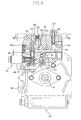
- Fig. 6 shows a cross sectional view taken along line VI-VI in Fig. 3. Further, Fig. 7 shows a cross sectional view taken along line VII-VII in Fig. 6.
- the charge pump case 82 is provided with a suction oil path 201 having a first end communicated with a suction port 81a of the charge pump body 81 and a second end opened outwardly, and a discharge oil path 202 having a first end communicated with a discharge port 81b of the charge pump body 81 and a second end branch-connected to various hydraulic circuit.
- the second end of the suction oil path 201 is connected to an optionally provided reservoir tank 250 via the oil path 211 such as a conduit into which a filter 210 is inserted.
- the discharge oil path 202 is branched into a working machine operating hydraulic circuit 300, a PTO hydraulic circuit 400 and a traveling-system hydraulic circuit 500 while being set to a predetermined pressure by a relief valve 220.
- the relief oil from the relief valve 220 is returned to the suction oil path 201 via the return oil path 203 arranged in the charge pump case 82 (see Figs. 2 and 6).
- the working machine operating hydraulic circuit 300 has a working machine operating oil path 301 for supplying pressure oil from the charge pump 80 toward the working machine such as a mower lifting device.
- the working machine operating oil path 301 is connected to the discharge oil path 202 via a sequence 310.
- the working machine operating oil path 301 is formed on the charge pump case 82 so as to have a first end communicated with the discharge oil path 202 and a second end opened to the exterior surface, as shown in Fig. 6.
- the path is opened to the exterior surface of the charge pump case (see Figs. 2 and 6).
- a spring chamber of the sequence 310 is opened into the housing through an oil path 302 formed in the charge pump case and the center section.
- the PTO hydraulic circuit 400 is configured so as to supply a part of the pressure oil of the discharge oil path 202 to the PTO device 50.
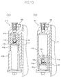
- Figs. 8 and 9 show cross sectional views taken along line VIII-VIII and line IX-IX in Fig. 3, respectively.
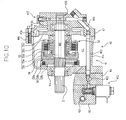
- Fig. 10 shows a cross sectional view taken along line X-X in Fig. 8.
- the PTO hydraulic circuit 400 includes a first PTO oil path 401 formed in the charge pump case 82 so as to have a first end connected to the discharge oil path 202 via a depressurizing valve 410 and a second end opened to the contacting surface with the center section 45 of the charge pump case 82, a second PTO oil path 402 formed in the center section 45 so as to communicate with the second end of the first PTO oil path 401, a third PTO oil path 403 arranged within the housing body 41 so as to have a first end connected to the second PTO oil path 402 and a second end extending to the lid member 47, and a fourth PTO oil path 404 formed in the lid member 47 so as to communicate to the second end of the third PTO oil path 403.
- a conduit extending between the center section 45 and the lid member 47 is used as the third PTO oil path 403, but an oil path may of course be formed in the peripheral wall 41c of the housing body 41 in place of the conduit.
- the PTO hydraulic circuit 400 further has a clutch operating oil path 405 perforated in the PTO shaft 51 so as to communicate with the fourth PTO oil path 404.
- the PTO shaft 51 is supported so as to be rotatable about the axis line by the first end wall of the housing body 41 and the lid member 47, as shown in Fig. 10.
- a seal case part 420 including a ring-shaped oil distributing chamber is formed at the support portion of the lid member 47 and the PTO shaft 51 to communicate the fourth PTO oil path 404 with the clutch operating oil path 405.
- the lid member 47 is provided with a drain oil path 408 having a first end communicated with the seal case part 420 and a second end opened into the housing 40 (see Fig. 8); thus, preventing the leakage oil leaking in the seal case part 420 from acting as a back pressure of the PTO shaft 51.
- the PTO hydraulic circuit 400 further has a PTO solenoid valve 411, a PTO relief valve 412 and an accumulator 413 in the oil path extending from the discharge oil path 202 to the PTO device 50.
- the PTO solenoid valve 411 is provided to selectively supply/block the pressure oil from the charge pump 80 to the hydraulic clutch 55 in the PTO device 50.
- the PTO solenoid valve 411 is arranged in the charge pump case 82 so as to be inserted into the first PTO oil path 401, as shown in Fig. 6.
- the PTO relief valve 412 is provided to set the pressure oil supplied to the hydraulic clutch 55 through the clutch operating oil path 405 to a predetermined oil pressure.
- the PTO relief valve 412 is arranged in the lid member 47 so as to be inserted into the fourth PTO oil path 404, as shown in Fig. 10.
- the drain oil from the PTO relief valve 412 is returned into the housing 41 via the drain oil path 412a formed in the lid member 47 (see Figs. 2, 8, 10).
- the accumulator 413 is provided to gradually increase the oil pressure of the clutch operating oil path 405 to the predetermined oil pressure set by the PTO relief valve 412.
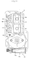
- Fig. 11 is an end view taken along line XI-XI in Fig. 3 and is an end view with the first and second hydraulic pump bodies 30a, 30b removed.
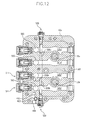
- Fig. 12 is a cross sectional view taken along line XII-XII in Fig. 3.
- the accumulator 413 includes an accumulator case 413a provided to the housing body 41, and an accumulator body 413b internally inserted into the accumulator case 413a.
- an accumulator oil path 406 which has a first end communicated with the second PTO oil path 402 and a second end opened to the exterior surface of the center section 45, is formed in the center section 45 (see Figs. 2 and 12).
- the second end of the accumulator oil path 406 and the accumulator 413 are communicated with each other by an appropriate conduit 407 (see Fig. 2).
- the accumulator case 413a is provided to the housing body 41, but of course, the accumulator body 413b may be inserted into the housing body 41, the charge pump case 82 or the center section 45, thus eliminating the accumulator case 413a. Further, an oil path substituting the conduit 47 can be perforated in the housing body 41.
- the accumulator 413 is provided to the housing body 41, and the PTO relief valve 412 is provided to the lid member 47, but in place thereof, both may be integrally provided.
- the PTO relief valve 412 may be inserted into the accumulator case 413 provided to the housing body 41.
- the machining step for installing the PTO relief valve 412 to the lid member 47 can be eliminated, thus reducing the machining cost of the lid member 47.
- the PTO relief valve 412 is arranged in the accumulator body 413b so that the pressure receiving chamber 412c opens to the pressure receiving surface of the accumulator body 413b.
- the relief setting spring 412b of the PTO relief valve 412 is set so that the biasing force thereof is greater than that of the spring 413c of the accumulator 413.
- Fig. 12 shows a cross sectional view taken along line XII-XII in Fig. 3.
- the traveling-system hydraulic circuit 500 includes a first hydraulic circuit 500a for fluidly connecting the first hydraulic pump body 30a to the first hydraulic motor unit 160a, and a second hydraulic circuit 500b for fluidly connecting the second hydraulic pump body 30b to the second hydraulic motor unit 160b.
- the first hydraulic circuit 500a and the second hydraulic circuit 500b have substantially the same configuration. Therefore, in the figure, same reference characters (or same reference character with a different subscript) are denoted for the members same as or corresponding to the first hydraulic circuit 500a and the detailed description of the second hydraulic circuit 500b will not be given herein.
- the first hydraulic circuit 500a connects the first hydraulic pump body 30a to the first hydraulic motor unit 160a so as to configure a closed circuit.
- the first hydraulic circuit 500a has a pair of first hydraulic lines 501a for connecting the first hydraulic pump body 30a to the first hydraulic motor unit 160a, and a charge line 502a for communicating between the pair of first hydraulic lines 501a.
- One of the pair of first hydraulic lines 501a communicates the discharge port in the first hydraulic pump body 30a with the suction port in the first hydraulic motor unit 160a, and the other of the pair of the first hydraulic line 501a communicates the suction port of the first hydraulic pump body 30a with the discharge port in the first hydraulic motor unit 160a.
- a pair of first oil paths 501a' forming a part of the pair of first hydraulic line 501 is formed in the center section 45.
- One of the pair of first oil paths 501a' has a first end communicated with the discharge port of the first hydraulic pump body 30a and a second end opened to the exterior surface of the center section 45.
- the other of the pair of the first oil path lines 501a' has a first end communicated with the suction port of the first hydraulic pump body 30a and a second end opened to the exterior surface of the center section 45.
- the charge line 502a is configured to supply the pressure oil from the charge pump 80 to each of the pair of first hydraulic lines 501a.
- the charge line 502a is formed at the center section 45 and the housing body 41.
- the charge line 502a has a pair of charge oil paths 503 formed in the center section 45 so as to have a first end communicated with each of the pair of first oil paths 501a' and a second end opened to the contacting surface with the housing body 41 in the center section 45, and a communication groove 504 formed on the contacting surface with the center section 45 of the first end wall 41a in the housing body 41 so as to communicate the second ends of the pair of charge oil paths 503.
- the discharge oil path 202 is connected to the communication groove 504.
- the discharge oil path 202 has a first portion 202a formed in the charge pump case 82, and a second portion 202b formed in the center section 45 so as to communicate with the first portion 202a and open to the communication groove 504.
- Reference numeral 505 in Fig. 11 denotes a drain groove formed on the contacting surface with the center section 45 in the first end wall 41a so as to surround the opening ends of the pair of charge oil paths 503 and the communication groove 504 in order to return the leakage oil, generated when flowing oil from the discharge oil path 202 to the charge line 502a, into to the housing 40.
- the charge line 502a further has a pair of check valves 510 arranged between the communication groove 504 and the pair of charge oil paths 503, respectively, as shown in Figs. 2, 4, 5 and 12.
- the pair of check valves 510 are provided to allow the flow of oil from the discharge oil path 202 to each of the pair of first oil path 501a', and to prevent the oil from flowing in the reverse direction.
- the check valve 510 is arranged on the mating surface of the center section 45 and the housing body 41.
- the charge line 502a may have a high-pressure relief valve 511 for setting the maximum oil pressure of each of the pair of first hydraulic lines 501a (or the pair of first oil paths 501a').
- the pair of first hydraulic lines 501a can be effectively prevented from becoming excessively high pressure.
- each of the pair of high-pressure relief valves 511 are arranged between the communication groove 504 and the pair of first oil paths 501a'.
- the charge line 502a may have an orifice 512 for communicating at least one of the pair of first hydraulic lines 501a to the external line or externally.
- the orifice 512 is arranged between one of the first oil paths 501a' (preferably, the first oil path 501a' that becomes high pressure when the vehicle moves backward) and the communication groove 504.
- the first hydraulic circuit 500a may include a bypass line 508a for communicating between the pair of first hydraulic lines 501a, and a bypass valve 520 inserted into the bypass line 508a so as to selectively communicate/block the bypass line 508a with the external operation.
- the pressure difference can be prevented from creating between the pair of first hydraulic lines 501a.
- the bypass line 508a is formed in the center section 45 so as to communicate between the pair of first oil paths 501a'.
- the traveling-system hydraulic circuit 500 further has a free wheel preventing check valve 530, as shown in Fig. 2.
- the free wheel preventing check valve 530 is provided to naturally resupply the oil to the pair of first and second hydraulic lines 501a, 501b when the amount of oil within the pair of first hydraulic lines 501a and the pair of second hydraulic lines 501b decrease for some reason.
- the vehicle axle can be effectively prevented from rotating uncontrollably in spite of keeping the first and second hydraulic pump bodies 30a, 30b in the neutral state.
- a suction oil path 505 which has a first end communicated with the housing 40 and a second end communicated with the discharge oil path 202, is formed on the charge pump case 802 and the center section 45.
- the free wheel preventing check valve 530 is inserted into the suction oil path 505.
- the pump unit 1 configures a traveling-system transmission mechanism by being fluidly connected to the pair of hydraulic motor unit 160a, 160b allocated and arranged in the width direction of the vehicle.
- the pump unit 1 can effectively prevent the traveling-system transmission mechanism from being arranged at the central portion in the width direction of the body frame 110 of the vehicle.
- the pump unit 1 has the pump accommodating section 42 and the PTO accommodating section 43 allocated and arranged on one side and the other side in the width direction of the housing 40 of the vehicle, respectively, and has the input shaft 10 supported on one side in the width direction of the vehicle rather than the PTO shaft 51.
- the driving source 150 is arranged at substantially the central portion in the width direction of the body frame 110 taking into consideration the vehicle balance (see Fig. 1(b)) and the like. Therefore, in order to perform the operative connection to the driving source 150 with a simple configuration, it is preferable to arrange the housing 40 so that the input shaft 10 is positioned at substantially the central portion in the width direction of the body frame 110.
- the pump unit 1 has the above configuration.
- the housing 40 is arranged so that the input shaft 10 is positioned at substantially the central portion in the width direction of the body frame 110, the PTO shaft 51 is displaced to and arranged on the other side of the width direction of the body frame of the vehicle.
- the pump unit 1 positioning of both the traveling-system transmission mechanism and the PTO-system transmission mechanism at the central portion in the width direction of the body frame 110 can be effectively prevented, and a free space at the central portion in the width direction of the body frame 110 can be secured. Therefore, the degree of freedom in design of the working vehicle can be improved. Further, in the working vehicle equipped with the ground working machine 140 having the input part not at the center but displaced to one side in the width direction of the vehicle, the transmission path to the input part of the ground working machine 140 can be readily made short and, therefore, is very effective.
- the input shaft 10 (or the single shaft 15) integrally formed with the first pump shaft 20a, the second pump shaft 20b and the PTO shaft 51 are arranged sequentially from one side to the other side in the width direction of the housing 40 of the vehicle.
- the power transmission from the input shaft 10 to the first pump shaft 20a, the second pump shaft 20b and the PTO shaft 51 can be carried out with a simple configuration while maintaining the distance between the axes of the input shaft 10 and the PTO shaft 51.
- the input shaft 10 and the first pump shaft 20a are integrally formed, but may also be formed with a separate shaft in which the relevant shafts are arranged concentrically.
- the input shaft 10 and the first pump shaft 20a are formed with a separate shaft
- the input shaft 10 is positioned so as to be closest to one side in the width direction of the housing 40 of the vehicle than any other shaft
- the PTO shaft 51 can be positioned so as to be closest to the other side in the width direction of the housing 40 of the vehicle than any other shaft.
Priority Applications (1)
| Application Number | Priority Date | Filing Date | Title |
|---|---|---|---|
| EP09155322A EP2065248A3 (fr) | 2003-11-11 | 2004-10-22 | Unité de pompe pour véhicule de travail |
Applications Claiming Priority (2)
| Application Number | Priority Date | Filing Date | Title |
|---|---|---|---|
| JP2003381523A JP4266781B2 (ja) | 2003-11-11 | 2003-11-11 | ポンプユニット |
| JP2003381523 | 2003-11-11 |
Related Child Applications (1)
| Application Number | Title | Priority Date | Filing Date |
|---|---|---|---|
| EP09155322A Division EP2065248A3 (fr) | 2003-11-11 | 2004-10-22 | Unité de pompe pour véhicule de travail |
Publications (3)
| Publication Number | Publication Date |
|---|---|
| EP1531077A2 true EP1531077A2 (fr) | 2005-05-18 |
| EP1531077A3 EP1531077A3 (fr) | 2006-07-12 |
| EP1531077B1 EP1531077B1 (fr) | 2009-04-22 |
Family
ID=34431427
Family Applications (2)
| Application Number | Title | Priority Date | Filing Date |
|---|---|---|---|
| EP09155322A Withdrawn EP2065248A3 (fr) | 2003-11-11 | 2004-10-22 | Unité de pompe pour véhicule de travail |
| EP04025195A Expired - Fee Related EP1531077B1 (fr) | 2003-11-11 | 2004-10-22 | Unité de pompe et véhicule de travail |
Family Applications Before (1)
| Application Number | Title | Priority Date | Filing Date |
|---|---|---|---|
| EP09155322A Withdrawn EP2065248A3 (fr) | 2003-11-11 | 2004-10-22 | Unité de pompe pour véhicule de travail |
Country Status (4)
| Country | Link |
|---|---|
| US (2) | US7299888B2 (fr) |
| EP (2) | EP2065248A3 (fr) |
| JP (1) | JP4266781B2 (fr) |
| DE (1) | DE602004020723D1 (fr) |
Cited By (3)
| Publication number | Priority date | Publication date | Assignee | Title |
|---|---|---|---|---|
| CN105658464A (zh) * | 2013-10-10 | 2016-06-08 | 技术推进公司 | 用于机动车辆的动力系统以及运行方法 |
| CN109322753A (zh) * | 2018-11-30 | 2019-02-12 | 恒天九五重工有限公司 | 一种防止工程机械加载起动时冒黑烟的方法 |
| EP3339657A4 (fr) * | 2015-08-19 | 2019-05-08 | Kanzaki Kokyukoki Mfg. Co., Ltd. | Procédé de formation de canal d'huile de fonctionnement dans un actionneur hydraulique |
Families Citing this family (9)
| Publication number | Priority date | Publication date | Assignee | Title |
|---|---|---|---|---|
| US7640738B1 (en) | 2002-06-19 | 2010-01-05 | Hydro-Gear Limited Partnership Ltd. | Hydraulic pump and motor module for use in a vehicle |
| AU2006270912B2 (en) * | 2005-07-19 | 2012-05-17 | Yanmar Co., Ltd. | Transmission |
| JP2007106138A (ja) * | 2005-09-13 | 2007-04-26 | Kanzaki Kokyukoki Mfg Co Ltd | 作業車両の動力伝達機構 |
| JP2008099557A (ja) * | 2006-09-19 | 2008-05-01 | Kanzaki Kokyukoki Mfg Co Ltd | 作業車輌の伝動構造 |
| JP2008157161A (ja) * | 2006-12-26 | 2008-07-10 | Kanzaki Kokyukoki Mfg Co Ltd | マルチポンプユニットおよびマルチポンプユニット付車両 |
| US9038753B2 (en) * | 2007-04-27 | 2015-05-26 | Leonard H. Hancock, SR. | Vehicle hydraulic system |
| US20090072509A1 (en) * | 2007-09-18 | 2009-03-19 | Climb Two One Ltd. | Running assisting device |
| US8002073B2 (en) * | 2008-04-22 | 2011-08-23 | Kanzaki Kokyukoki Mfg. Co., Ltd. | Hydraulic drive working vehicle |
| IT201900005240A1 (it) * | 2019-04-05 | 2020-10-05 | Cnh Ind Italia Spa | Disposizione idraulica di filtraggio e risucchio di olio idraulico per un veicolo da lavoro |
Citations (1)
| Publication number | Priority date | Publication date | Assignee | Title |
|---|---|---|---|---|
| EP1350421A1 (fr) * | 2002-04-03 | 2003-10-08 | Kanzaki Kokyukoki MFG. Co., Ltd. | Pompe et véhicule de travail |
Family Cites Families (41)
| Publication number | Priority date | Publication date | Assignee | Title |
|---|---|---|---|---|
| US3292723A (en) * | 1965-03-04 | 1966-12-20 | Sundstrand Corp | Hydrostatic transmission |
| US3469381A (en) * | 1966-12-09 | 1969-09-30 | Deere & Co | Hydraulic drive and controls for a self-propelled windrower |
| US3481419A (en) * | 1967-11-28 | 1969-12-02 | Deere & Co | Auxiliary hydrostatic front wheel drive system with drive motors connected for parallel or series operation |
| GB1580804A (en) * | 1976-05-20 | 1980-12-03 | Massey Ferguson Services Nv | Vehicle with hydrostatic transmission |
| US4124079A (en) * | 1976-09-30 | 1978-11-07 | Crow Harold J | Driven implement connected to rockable motor of a vehicle |
| US4395865A (en) | 1981-01-28 | 1983-08-02 | Davis Jr Robert D | Self propelled lawn mower |
| JPS60135226U (ja) * | 1984-02-20 | 1985-09-09 | 株式会社神崎高級工機製作所 | 自走式作業車のトランスミツシヨン |
| JPS63106136A (ja) * | 1986-10-24 | 1988-05-11 | Kanzaki Kokyukoki Mfg Co Ltd | 自走式作業車のトランスミツシヨン |
| JPH0740108Y2 (ja) * | 1987-03-12 | 1995-09-13 | トヨタ自動車株式会社 | 車両用動力伝達装置 |
| US4886142A (en) * | 1987-06-26 | 1989-12-12 | Kanzaki Kokyukoki Mfg. Co. Ltd. | Hydraulic four-wheel drive system |
| JP2538356B2 (ja) * | 1989-11-20 | 1996-09-25 | 株式会社神崎高級工機製作所 | 自走式作業車のトランスミツシヨン装置 |
| JP3769031B2 (ja) * | 1993-09-17 | 2006-04-19 | 株式会社 神崎高級工機製作所 | 車輌の走行用トランスミッション |
| US5918691A (en) * | 1994-05-23 | 1999-07-06 | Kanzaki Kokyokoki Mfg. Co., Ltd. | Axle driving apparatus |
| US5809756A (en) | 1994-11-08 | 1998-09-22 | Scag; Dane T. | Lawn mower usable in both riding and walk-behind modes |
| US6325166B1 (en) * | 1996-09-13 | 2001-12-04 | Yanmar Agricultural Equipment Co., Ltd. | Hydraulic travelling agricultural machine |
| JPH1095360A (ja) * | 1996-09-20 | 1998-04-14 | Yanmar Agricult Equip Co Ltd | 走行ミッション装置の操舵機構 |
| EP1745973A1 (fr) * | 1997-07-22 | 2007-01-24 | Kanzaki Kokyukoki Mfg. Co., Ltd. | Dispositif de propulsion pour véhicule de travail |
| JP3636594B2 (ja) * | 1998-05-26 | 2005-04-06 | 株式会社クボタ | トラクタの伝動装置 |
| WO1999064264A1 (fr) * | 1998-06-05 | 1999-12-16 | Kanzaki Kokyukoki Mfg. Co., Ltd. | Dispositif de transmission pour vehicule a transmission hydrostatique, et source de pression hydraulique a cet effet |
| JP4031572B2 (ja) | 1998-07-08 | 2008-01-09 | 株式会社 神崎高級工機製作所 | 車両の操向駆動装置 |
| US6578656B2 (en) * | 1998-09-03 | 2003-06-17 | Kubota Corporation | Riding mower |
| JP3488125B2 (ja) | 1999-03-23 | 2004-01-19 | 株式会社クボタ | 乗用型芝刈機 |
| US6332393B1 (en) * | 1999-07-16 | 2001-12-25 | Hydro-Gear Limited Partnership | Pump |
| US6425244B1 (en) * | 1999-10-18 | 2002-07-30 | Kanzaki Kokyukoki Mfg. Co., Ltd. | Pump unit |
| DE10051620A1 (de) * | 1999-10-18 | 2001-05-17 | Kanzaki Kokyukoki Mfg Co Ltd | Tandem-Pumpeneinheit |
| US7677038B2 (en) * | 1999-10-18 | 2010-03-16 | Kanzaki Kokyukoki Mfg. Co., Ltd. | Pump unit |
| JP2002087086A (ja) * | 2000-07-10 | 2002-03-26 | Kanzaki Kokyukoki Mfg Co Ltd | 作業車両の動力取出し装置 |
| JP2002205561A (ja) | 2001-01-12 | 2002-07-23 | Kanzaki Kokyukoki Mfg Co Ltd | 走行用静油圧式無段変速装置 |
| US6601474B2 (en) * | 2000-09-05 | 2003-08-05 | Kanzaki Kokyukoki Mfg. Co., Ltd. | Hydrostatic transmission and power train for vehicle |
| JP3827959B2 (ja) | 2001-02-13 | 2006-09-27 | 株式会社クボタ | 草刈り機 |
| JP3907452B2 (ja) * | 2001-11-27 | 2007-04-18 | 株式会社クボタ | 草刈機 |
| JP2003276461A (ja) | 2002-01-18 | 2003-09-30 | Kanzaki Kokyukoki Mfg Co Ltd | 作業車輌 |
| US6672843B1 (en) * | 2002-04-08 | 2004-01-06 | Hydro-Gear Limited Partnership | Dual pump apparatus comprising dual drive shafts and auxiliary pump |
| US6705840B1 (en) * | 2002-06-19 | 2004-03-16 | Hydro-Gear Limited Partnership | Inline tandem pump |
| US6840879B1 (en) * | 2002-09-03 | 2005-01-11 | Hydro-Gear Limited Partnership | Hydraulic motor apparatus |
| US6811509B1 (en) * | 2002-09-03 | 2004-11-02 | Hydro-Gear Limited Partnership | Hydraulic motor apparatus including brake mechanism |
| US7044259B2 (en) * | 2003-04-10 | 2006-05-16 | Kerwyn Stoll | Hydraulic transmission for driving and steering wheels |
| US7004268B2 (en) * | 2003-06-06 | 2006-02-28 | Koji Irikura | Vehicle having twin transmissions for driving respective wheels |
| US6935454B1 (en) * | 2003-09-18 | 2005-08-30 | Hydro-Gear Limited Partnership | Valve for a hydraulic drive apparatus |
| EP1586775A3 (fr) * | 2004-04-13 | 2011-11-09 | Kanzaki Kokyukoki Mfg. Co., Ltd. | Dispositif de vidange pour système d'entraînement hydraulique |
| JP2008157161A (ja) * | 2006-12-26 | 2008-07-10 | Kanzaki Kokyukoki Mfg Co Ltd | マルチポンプユニットおよびマルチポンプユニット付車両 |
-
2003
- 2003-11-11 JP JP2003381523A patent/JP4266781B2/ja not_active Expired - Fee Related
-
2004
- 2004-10-22 EP EP09155322A patent/EP2065248A3/fr not_active Withdrawn
- 2004-10-22 EP EP04025195A patent/EP1531077B1/fr not_active Expired - Fee Related
- 2004-10-22 DE DE602004020723T patent/DE602004020723D1/de not_active Expired - Fee Related
- 2004-11-05 US US10/981,539 patent/US7299888B2/en not_active Expired - Fee Related
-
2007
- 2007-01-16 US US11/623,687 patent/US7775309B2/en not_active Expired - Fee Related
Patent Citations (1)
| Publication number | Priority date | Publication date | Assignee | Title |
|---|---|---|---|---|
| EP1350421A1 (fr) * | 2002-04-03 | 2003-10-08 | Kanzaki Kokyukoki MFG. Co., Ltd. | Pompe et véhicule de travail |
Cited By (5)
| Publication number | Priority date | Publication date | Assignee | Title |
|---|---|---|---|---|
| CN105658464A (zh) * | 2013-10-10 | 2016-06-08 | 技术推进公司 | 用于机动车辆的动力系统以及运行方法 |
| CN105658464B (zh) * | 2013-10-10 | 2018-09-28 | 技术推进公司 | 用于机动车辆的动力系统以及运行方法 |
| EP3339657A4 (fr) * | 2015-08-19 | 2019-05-08 | Kanzaki Kokyukoki Mfg. Co., Ltd. | Procédé de formation de canal d'huile de fonctionnement dans un actionneur hydraulique |
| CN109322753A (zh) * | 2018-11-30 | 2019-02-12 | 恒天九五重工有限公司 | 一种防止工程机械加载起动时冒黑烟的方法 |
| CN109322753B (zh) * | 2018-11-30 | 2021-04-20 | 恒天九五重工有限公司 | 一种防止工程机械加载起动时冒黑烟的方法 |
Also Published As
| Publication number | Publication date |
|---|---|
| EP2065248A3 (fr) | 2009-06-17 |
| JP4266781B2 (ja) | 2009-05-20 |
| DE602004020723D1 (de) | 2009-06-04 |
| US20050098363A1 (en) | 2005-05-12 |
| US20070163817A1 (en) | 2007-07-19 |
| EP2065248A2 (fr) | 2009-06-03 |
| JP2005145110A (ja) | 2005-06-09 |
| EP1531077A3 (fr) | 2006-07-12 |
| US7299888B2 (en) | 2007-11-27 |
| EP1531077B1 (fr) | 2009-04-22 |
| US7775309B2 (en) | 2010-08-17 |
Similar Documents
| Publication | Publication Date | Title |
|---|---|---|
| US7775309B2 (en) | Pump unit | |
| US7374010B2 (en) | Transmission for a working vehicle and vehicle | |
| EP1350421B1 (fr) | Pompe et véhicule de travail | |
| EP1413498B1 (fr) | Véhicule à quatre roues motrices | |
| US7237642B2 (en) | Frame structure of a vehicle | |
| US7409827B2 (en) | Working vehicle | |
| US8281892B2 (en) | Working vehicle and HST unit | |
| JP4132926B2 (ja) | ポンプユニット及び作業車 | |
| US20090126328A1 (en) | Working Vehicle With Front-Mount Mower | |
| US7523609B2 (en) | Hydrostatic transmission | |
| JP4568805B2 (ja) | 車輌におけるpto装置 | |
| JP2007302146A (ja) | トランスミッション | |
| JP2007303580A (ja) | アキシャルピストン装置 | |
| JP2008099557A (ja) | 作業車輌の伝動構造 |
Legal Events
| Date | Code | Title | Description |
|---|---|---|---|
| PUAI | Public reference made under article 153(3) epc to a published international application that has entered the european phase |
Free format text: ORIGINAL CODE: 0009012 |
|
| AK | Designated contracting states |
Kind code of ref document: A2 Designated state(s): AT BE BG CH CY CZ DE DK EE ES FI FR GB GR HU IE IT LI LU MC NL PL PT RO SE SI SK TR |
|
| AX | Request for extension of the european patent |
Extension state: AL HR LT LV MK |
|
| PUAL | Search report despatched |
Free format text: ORIGINAL CODE: 0009013 |
|
| AK | Designated contracting states |
Kind code of ref document: A3 Designated state(s): AT BE BG CH CY CZ DE DK EE ES FI FR GB GR HU IE IT LI LU MC NL PL PT RO SE SI SK TR |
|
| AX | Request for extension of the european patent |
Extension state: AL HR LT LV MK |
|
| 17P | Request for examination filed |
Effective date: 20060811 |
|
| 17Q | First examination report despatched |
Effective date: 20061013 |
|
| AKX | Designation fees paid |
Designated state(s): DE FR GB |
|
| GRAP | Despatch of communication of intention to grant a patent |
Free format text: ORIGINAL CODE: EPIDOSNIGR1 |
|
| GRAS | Grant fee paid |
Free format text: ORIGINAL CODE: EPIDOSNIGR3 |
|
| GRAL | Information related to payment of fee for publishing/printing deleted |
Free format text: ORIGINAL CODE: EPIDOSDIGR3 |
|
| GRAS | Grant fee paid |
Free format text: ORIGINAL CODE: EPIDOSNIGR3 |
|
| GRAA | (expected) grant |
Free format text: ORIGINAL CODE: 0009210 |
|
| AK | Designated contracting states |
Kind code of ref document: B1 Designated state(s): DE FR GB |
|
| REG | Reference to a national code |
Ref country code: GB Ref legal event code: FG4D |
|
| REF | Corresponds to: |
Ref document number: 602004020723 Country of ref document: DE Date of ref document: 20090604 Kind code of ref document: P |
|
| PLBE | No opposition filed within time limit |
Free format text: ORIGINAL CODE: 0009261 |
|
| STAA | Information on the status of an ep patent application or granted ep patent |
Free format text: STATUS: NO OPPOSITION FILED WITHIN TIME LIMIT |
|
| 26N | No opposition filed |
Effective date: 20100125 |
|
| REG | Reference to a national code |
Ref country code: FR Ref legal event code: ST Effective date: 20100630 |
|
| PG25 | Lapsed in a contracting state [announced via postgrant information from national office to epo] |
Ref country code: FR Free format text: LAPSE BECAUSE OF NON-PAYMENT OF DUE FEES Effective date: 20091102 Ref country code: DE Free format text: LAPSE BECAUSE OF NON-PAYMENT OF DUE FEES Effective date: 20100501 |
|
| PG25 | Lapsed in a contracting state [announced via postgrant information from national office to epo] |
Ref country code: GB Free format text: LAPSE BECAUSE OF NON-PAYMENT OF DUE FEES Effective date: 20091022 |