EP1530071A2 - Zoomlinse und Bildaufnahmevorrichtung - Google Patents
Zoomlinse und Bildaufnahmevorrichtung Download PDFInfo
- Publication number
- EP1530071A2 EP1530071A2 EP04256817A EP04256817A EP1530071A2 EP 1530071 A2 EP1530071 A2 EP 1530071A2 EP 04256817 A EP04256817 A EP 04256817A EP 04256817 A EP04256817 A EP 04256817A EP 1530071 A2 EP1530071 A2 EP 1530071A2
- Authority
- EP
- European Patent Office
- Prior art keywords
- lens
- lens unit
- unit
- image
- zoom
- Prior art date
- Legal status (The legal status is an assumption and is not a legal conclusion. Google has not performed a legal analysis and makes no representation as to the accuracy of the status listed.)
- Granted
Links
- 230000003287 optical effect Effects 0.000 claims abstract description 121
- 230000014509 gene expression Effects 0.000 claims description 107
- 239000000463 material Substances 0.000 claims description 32
- 238000006243 chemical reaction Methods 0.000 claims description 30
- 230000002829 reductive effect Effects 0.000 claims description 22
- 108010001267 Protein Subunits Proteins 0.000 claims description 7
- 230000004075 alteration Effects 0.000 abstract description 92
- 238000010586 diagram Methods 0.000 description 66
- 230000036961 partial effect Effects 0.000 description 22
- 230000007246 mechanism Effects 0.000 description 14
- 230000003247 decreasing effect Effects 0.000 description 12
- 230000000754 repressing effect Effects 0.000 description 11
- 230000035945 sensitivity Effects 0.000 description 9
- 230000004044 response Effects 0.000 description 8
- 230000009467 reduction Effects 0.000 description 7
- 230000004907 flux Effects 0.000 description 6
- 201000009310 astigmatism Diseases 0.000 description 5
- 238000006073 displacement reaction Methods 0.000 description 5
- 239000011521 glass Substances 0.000 description 4
- 230000002093 peripheral effect Effects 0.000 description 4
- 239000004973 liquid crystal related substance Substances 0.000 description 3
- 238000005549 size reduction Methods 0.000 description 3
- 230000007423 decrease Effects 0.000 description 2
- 239000013585 weight reducing agent Substances 0.000 description 2
- 206010010071 Coma Diseases 0.000 description 1
- 239000000470 constituent Substances 0.000 description 1
- 230000001747 exhibiting effect Effects 0.000 description 1
- 238000009432 framing Methods 0.000 description 1
- 230000000670 limiting effect Effects 0.000 description 1
Images


Classifications
-
- G—PHYSICS
- G02—OPTICS
- G02B—OPTICAL ELEMENTS, SYSTEMS OR APPARATUS
- G02B15/00—Optical objectives with means for varying the magnification
- G02B15/14—Optical objectives with means for varying the magnification by axial movement of one or more lenses or groups of lenses relative to the image plane for continuously varying the equivalent focal length of the objective
- G02B15/16—Optical objectives with means for varying the magnification by axial movement of one or more lenses or groups of lenses relative to the image plane for continuously varying the equivalent focal length of the objective with interdependent non-linearly related movements between one lens or lens group, and another lens or lens group
- G02B15/163—Optical objectives with means for varying the magnification by axial movement of one or more lenses or groups of lenses relative to the image plane for continuously varying the equivalent focal length of the objective with interdependent non-linearly related movements between one lens or lens group, and another lens or lens group having a first movable lens or lens group and a second movable lens or lens group, both in front of a fixed lens or lens group
- G02B15/167—Optical objectives with means for varying the magnification by axial movement of one or more lenses or groups of lenses relative to the image plane for continuously varying the equivalent focal length of the objective with interdependent non-linearly related movements between one lens or lens group, and another lens or lens group having a first movable lens or lens group and a second movable lens or lens group, both in front of a fixed lens or lens group having an additional fixed front lens or group of lenses
- G02B15/17—Optical objectives with means for varying the magnification by axial movement of one or more lenses or groups of lenses relative to the image plane for continuously varying the equivalent focal length of the objective with interdependent non-linearly related movements between one lens or lens group, and another lens or lens group having a first movable lens or lens group and a second movable lens or lens group, both in front of a fixed lens or lens group having an additional fixed front lens or group of lenses arranged +--
-
- G—PHYSICS
- G02—OPTICS
- G02B—OPTICAL ELEMENTS, SYSTEMS OR APPARATUS
- G02B15/00—Optical objectives with means for varying the magnification
- G02B15/14—Optical objectives with means for varying the magnification by axial movement of one or more lenses or groups of lenses relative to the image plane for continuously varying the equivalent focal length of the objective
- G02B15/144—Optical objectives with means for varying the magnification by axial movement of one or more lenses or groups of lenses relative to the image plane for continuously varying the equivalent focal length of the objective having four groups only
- G02B15/1441—Optical objectives with means for varying the magnification by axial movement of one or more lenses or groups of lenses relative to the image plane for continuously varying the equivalent focal length of the objective having four groups only the first group being positive
- G02B15/144109—Optical objectives with means for varying the magnification by axial movement of one or more lenses or groups of lenses relative to the image plane for continuously varying the equivalent focal length of the objective having four groups only the first group being positive arranged +--+
-
- G—PHYSICS
- G02—OPTICS
- G02B—OPTICAL ELEMENTS, SYSTEMS OR APPARATUS
- G02B15/00—Optical objectives with means for varying the magnification
- G02B15/14—Optical objectives with means for varying the magnification by axial movement of one or more lenses or groups of lenses relative to the image plane for continuously varying the equivalent focal length of the objective
- G02B15/144—Optical objectives with means for varying the magnification by axial movement of one or more lenses or groups of lenses relative to the image plane for continuously varying the equivalent focal length of the objective having four groups only
- G02B15/1441—Optical objectives with means for varying the magnification by axial movement of one or more lenses or groups of lenses relative to the image plane for continuously varying the equivalent focal length of the objective having four groups only the first group being positive
- G02B15/144113—Optical objectives with means for varying the magnification by axial movement of one or more lenses or groups of lenses relative to the image plane for continuously varying the equivalent focal length of the objective having four groups only the first group being positive arranged +-++
-
- G—PHYSICS
- G02—OPTICS
- G02B—OPTICAL ELEMENTS, SYSTEMS OR APPARATUS
- G02B15/00—Optical objectives with means for varying the magnification
- G02B15/14—Optical objectives with means for varying the magnification by axial movement of one or more lenses or groups of lenses relative to the image plane for continuously varying the equivalent focal length of the objective
- G02B15/145—Optical objectives with means for varying the magnification by axial movement of one or more lenses or groups of lenses relative to the image plane for continuously varying the equivalent focal length of the objective having five groups only
- G02B15/1451—Optical objectives with means for varying the magnification by axial movement of one or more lenses or groups of lenses relative to the image plane for continuously varying the equivalent focal length of the objective having five groups only the first group being positive
- G02B15/145125—Optical objectives with means for varying the magnification by axial movement of one or more lenses or groups of lenses relative to the image plane for continuously varying the equivalent focal length of the objective having five groups only the first group being positive arranged +--++
-
- G—PHYSICS
- G02—OPTICS
- G02B—OPTICAL ELEMENTS, SYSTEMS OR APPARATUS
- G02B15/00—Optical objectives with means for varying the magnification
- G02B15/14—Optical objectives with means for varying the magnification by axial movement of one or more lenses or groups of lenses relative to the image plane for continuously varying the equivalent focal length of the objective
- G02B15/16—Optical objectives with means for varying the magnification by axial movement of one or more lenses or groups of lenses relative to the image plane for continuously varying the equivalent focal length of the objective with interdependent non-linearly related movements between one lens or lens group, and another lens or lens group
- G02B15/163—Optical objectives with means for varying the magnification by axial movement of one or more lenses or groups of lenses relative to the image plane for continuously varying the equivalent focal length of the objective with interdependent non-linearly related movements between one lens or lens group, and another lens or lens group having a first movable lens or lens group and a second movable lens or lens group, both in front of a fixed lens or lens group
- G02B15/167—Optical objectives with means for varying the magnification by axial movement of one or more lenses or groups of lenses relative to the image plane for continuously varying the equivalent focal length of the objective with interdependent non-linearly related movements between one lens or lens group, and another lens or lens group having a first movable lens or lens group and a second movable lens or lens group, both in front of a fixed lens or lens group having an additional fixed front lens or group of lenses
- G02B15/173—Optical objectives with means for varying the magnification by axial movement of one or more lenses or groups of lenses relative to the image plane for continuously varying the equivalent focal length of the objective with interdependent non-linearly related movements between one lens or lens group, and another lens or lens group having a first movable lens or lens group and a second movable lens or lens group, both in front of a fixed lens or lens group having an additional fixed front lens or group of lenses arranged +-+
Definitions
- the present invention relates to a zoom lens, and more particularly, to a zoom lens suitable for an image-taking system such as an electronic camera (such as a video camera, or a digital still camera, etc.), a film camera, a broadcasting camera, etc.
- zoom lenses used for image-taking systems such as television cameras, video cameras, etc.
- image-taking apparatuses such as television cameras, video cameras, etc.
- a large aperture ratio, a large zoom ratio, and a wide field angle in addition to being a small-size lens system as a whole.
- zoom lenses four lens units including, in order from an object side to an image side, a first lens unit (focus lens unit) having a positive refractive power for focusing, a second lens unit (zoom lens unit) having a negative refractive power for zooming, a third lens unit (compensation lens unit) having a positive or negative refractive power for correcting for the variation of image surface during zooming, an aperture stop, and a fourth lens unit (relay lens unit) having a positive refractive power for forming an image is disclosed, for example, in Patent Documents 1 to 5.
- a front focusing type arranged focus lens unit closer to the object side than the zoom lens unit is more advantageous for a manual focusing type, since the amount of movement of the focus lens unit does not vary even during zooming when an object distance is constant. For this reason, the front focusing types are widely employed in broadcasting zoom lens or in commercially used zoom lens which requires many manual operations.
- a rear focusing type arranged focus lens unit closer to the image side than the zoom lens unit is widely employed in auto focusing zoom lens type, since it is advantageous for decreasing the size and weight of the focus lens unit.
- a zoom lens including five lens units, that is, in order from the object side to the image side, a first lens unit having a positive refractive power, a second lens unit having a negative refractive power, a third lens unit having a positive refractive power, a fourth lens unit having a negative refractive power, and a fifth lens unit having a positive refractive power
- a rear focusing type zoom lens in which the zooming is performed from the wide-angle end to the telephoto end by moving the second lens unit to the image side. Also, the variation of image surface due to the zooming is corrected by moving the fourth lens unit, and the focusing operation is performed by moving the fourth lens unit.
- a zoom lens including five lens units, that is, in order from the object side to the image side, a first lens unit having a positive refractive power and being fixed during zooming, a second lens unit, used for zooming, having a negative refractive power, a third lens unit having a positive refractive power, a fourth lens unit having a negative refractive power, and a fifth lens unit having a positive refractive power and correcting the variation of image surface caused by the zooming
- a rear focusing type zoom lens in which at least one of the third lens unit and the fourth lens unit is moved during the zooming and the fifth lens unit is moved during focusing operation.
- the fourth lens unit has one negative lens element and two positive lens elements, in order from the object side to the image side.
- the incident reduced tilt angle ⁇ 4 of the axial ray to the fourth lens unit is large, variation of an incident height h4 of the axial ray becomes large during focusing operation with the fourth lens unit, such that variations of axial aberrations such as spherical aberration, longitudinal chromatic aberration, etc., tend to increase.
- the fourth lens unit has one negative lens element and two positive lens elements, in order from the object side to the image side.
- an Abbe's number v4n of a material of the negative lens element and Abbe's numbers v4p of materials of the positive lens elements are close each other, the curvatures of the respective lens elements in the fourth lens unit are increased, thereby increasing the off-axial aberration during focusing operation.
- the weight of the fourth lens unit is increased and because a larger driving power for focusing operation is needed, the power consumption or the size of a driving mechanism tends to be increased.
- the refractive power of the fourth lens unit since the refractive power of the fourth lens unit is repressed and small, a new lens unit having a positive refractive power for converging the light flux diverging from the third lens unit must be arranged closer to the object side than the aperture stop. Further, in order to alleviate the degree of divergence of the light flux from the third lens unit, the refractive power of the third lens unit must be reduced. As a result, the amount of movement of the third lens unit during zooming tends to be increased, such that the total length of the zoom lens tends to be increased.
- a zoom lens of the rear focusing type is also disclosed, for example, in Patent Documents 9 to 13.
- an image-forming point At a zoom position with a focal length f of a zoom lens unit, let us define an image-forming point as being i0 when an object is at infinity and the image-forming point as being i(obj) when an object distance is obj.
- the zoom ratio is increased, the movement amount of the partial system FR during focusing operation is increased and the space for moving the partial system FR is increased.
- the driving power for moving the partial system FR by a desired amount is also increased, thereby increasing the overall size of the zoom lens.
- the zoom lens disclosed in Patent Document 12 described above is comprised four lens units including lens units having positive, negative, positive, and positive refractive powers, in order from the object side to the image side, and since the fourth lens unit is shared for use as a compensator (for correcting for the movement of image surface due to the zooming) and for use of focusing operation, there is a problem in that the zoom operation cannot be performed manually.
- the zoom lens disclosed in Patent Document 6 is a zoom lens including four lens units having positive, negative, negative, and positive refractive powers, in order from the object side to the image side, and the first lens unit is used for the manual focusing operation, the second lens unit is used as a variator (zoom lens unit), the third lens unit is used as a compensator (image surface-movement correcting unit), and the lens unit closer to the image side than the fourth lens unit is used as the focus lens unit for auto focusing operation.
- the zoom lens disclosed in Patent Document 6 has a relatively small zoom ratio of 6 times or less, and the focal length at the zoom position of the telephoto end is relatively short, more or less 70 mm. For this reason, if the zoom ratio is further increased and if the focal length at the telephoto end is increased, the movement amount of the lens unit closer to the image side than the fourth lens unit is rapidly increased during focusing operation, so that there is a problem in that the whole zoom lens is large-sized.
- a zoom lens comprising, in order from an object side to an image side, a first lens unit having a positive optical power, a second lens unit having a negative optical power, a third lens unit having a negative optical power, a fourth lens unit having a positive optical power, and a fifth lens unit having a positive optical power. Further, the second lens unit and the third lens unit are moved during zooming and the fifth lens unit is moved during focusing.
- the fifth lens unit consists of one negative lens element G51 and two positive lens elements G52 and G53 in order from the object side to the image side, and the following conditional expressions are satisfied: 0 ⁇ ⁇ 5 ⁇ 0.35 1.85 ⁇ ⁇ 5p/ ⁇ 5n where ⁇ 5 represents an incident reduced tilt angle of an axial marginal ray to the fifth lens unit in a case where it is normalized to an optical power ⁇ w at a wide-angle end of the whole zoom lens, ⁇ 5p represents an average value of Abbe's numbers of materials of the positive lens elements G52 and G53, ⁇ 5n is an Abbe's number of a material of the negative lens element G51.
- a zoom lens comprising, in order from an object side to an image side, a first lens unit having a positive optical power, a second lens unit having a negative optical power, a third lens unit having one of positive and negative optical powers, and a fourth lens unit having a positive optical power. And, the second lens unit and the third lens unit are moved during zooming
- the fourth lens unit has a 4a lens sub-unit, a 4b lens sub-unit, and a 4c lens sub-unit, in order from the object side to the image side. Focusing is performed by moving the 4b lens sub-unit.
- the following conditional expression is satisfied: 1 ⁇
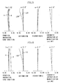
- FIG. 1 shows a cross-sectional view of a zoom lens at a wide-angle end according to Embodiment 1 (Numerical Example 1) of the present invention of the zoom lens.
- FIG.7 shows a cross-sectional view of a zoom lens at a wide-angle end according to Embodiment 2 (Numerical Example 2) of the present invention
- FIG. 13 shows a conceptual diagram of arrangement of a fifth lens unit in the zoom lens according to Embodiments 1 and 2
- FIG. 14 shows a conceptual diagram of arrangement of a fourth lens unit in the zoom lens.
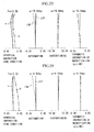
- FIG. 15 shows a cross-sectional view of a zoom lens according to Embodiment 3 (Numerical Example 3) of the present invention at a wide-angle end
- a reference character f denotes a focal length.
- an object distance refers to the distance as measured from an image surface.
- the zoom lens according to each respective embodiment is an image-taking optical system used for a image-taking system (image-taking apparatus) as will be described, and in the cross-sectional views of a lens system, the left side is an object side (front side) and the right side is an image side (rear side).
- a reference character L2 denotes a second lens unit having a negative refractive power
- a reference character L3 denotes a third lens unit having a negative refractive power
- a reference character L4 denotes a fourth lens unit having a positive refractive power
- a reference character L5 denotes a fifth lens unit having a positive refractive power.
- a reference character SP denotes an aperture stop and is positioned at the object side of the fourth lens unit L4.
- a reference character P denotes an optical element corresponding to an optical filter, a faceplate, a color-separating prism, etc.
- a reference character IP denotes an image surface.
- a solid-state image pickup device photoelectric conversion element
- a film plane is disposed on the image surface IP.
- reference characters e and g denote the e line and g line, respectively
- reference characters ⁇ M and ⁇ S denote a meridional image surface and a sagittal image surface, respectively
- a chromatic aberration of magnification is specified by the g line.
- operability of the manual focusing is improved by moving the first lens unit L1 during the manual focusing operation.
- the image-forming point i0 when the object distance is at infinity and the image-forming point as being i(obj) when the object distance is obj.
- the feed amount ⁇ xFF of the focusing partial system FF of the partial system B1 is not varied regardless of the zooming condition.
- the movement amount ⁇ xFR increases proportionally to the square of the image-forming magnification ⁇ B2 of the zoom lens unit.
- the movement amount due to the zooming is not varied, so that an electrical driving mechanism is not necessary.
- FIG. 1 shows a cross-sectional view of the zoom lens at the wide-angle end according to Numerical Example 1 of the present invention.
- a reference character L1 denotes a front lens unit having a positive refractive power as a first lens unit.
- a reference character L2 denotes a variator lens unit having a negative refractive power for zooming operation as a second lens unit and performs zooming from the wide-angle end to the telephoto end with monotonous movement to the image surface side on the optical axis.
- a reference character L3 denotes a compensator lens unit having a negative refractive power as a third lens unit and is nonlinearly moved on the optical axis along a convex track toward the object side so as to correct for the variation of image surface due to the zooming.
- the variator lens unit L2 and the compensator lens unit L3 constitute a zoom system.
- a reference character SP denotes an aperture stop and a reference character L4 denotes a relay lens unit having a positive refractive power as a fourth lens unit and being fixed (not moved) during the zooming.
- a reference character L5 denotes a focus lens unit having a positive refractive power as a fifth lens unit.
- the fifth lens unit L5 is a rear focus lens unit having a positive refractive power as a whole, and is moved on the optical axis toward the object side when achieving the in-focus in response to a close range object.
- the movement amount of the fifth lens unit L5 is -13.24 mm with the sign of the movement amount toward the image side set to be the positive direction, and the movement amount ⁇ x of the fifth lens unit is -1.742 in the case where it is normalized to the refractive power ⁇ w at the wide-angle end.
- the fifth lens unit L5 comprises three lens elements G51, G52, and G53 having negative, positive, and positive refractive powers, respectively, in order from the object side to the image side.
- the negative lens element G51 By disposing the negative lens element G51 among these lenses closest to the object side, the incident height of the axial ray at the negative lens element G51 is increased, so that it is possible to correct for the chromatic aberration with a less refractive power. As a result, it is possible to repress generation of all aberrations and to accomplish weight reduction in the fifth lens unit L5.
- Table 1 shows paraxial tracking values when the focal length at the wide-angle end is normalized to 1 in Numerical Example 1. From Table 1, since the incident reduced tilt angle ⁇ 5 of the fifth lens unit L5 is 0.29, Conditional Expression (4) is satisfied.
- the refractive power ⁇ 5 of the fifth lens unit L5 is 0.149445
- the incident height hb5 of the off-axial principal ray is 0.859734
- the emergent reduced tilt angle ⁇ b5' is -0.158024. Therefore, the middle term of Conditional Expression (7) is calculated to be 0.175 and thus Conditional Expression (7) is satisfied, thereby repressing the variation of the field angle due to the focusing operation.
- the fourth lens unit L4 is a fixed lens unit having a positive refractive power as a whole.
- the fourth lens unit L4 of the present embodiment comprises three lens elements G41, G42, and G43 having positive, negative, and positive refractive powers, respectively, in order from the object side to the image side.
- the refractive index Nn of the material of the negative lens element G42 of the fourth lens unit L4 is 1.81078, the Abbe's number v4n thereof is 40.9, the average value Np of the refractive indexes of the materials of the positive lens elements G41 and G43 is 1.60548, and the average value v4p of the Abbe's numbers thereof is 60.6.
- the refractive power ⁇ 4 of the fourth lens unit L4 is 0.252140.
- the first lens unit L1 it is also possible to move the first lens unit L1 as the focus lens unit on the optical axis.
- the first lens unit L1 is used for the manual focusing operation, the variation of movement amount due to the zooming does not occur, so that an electrical driving mechanism is not necessary and it is thus possible to realize a focusing mechanism with excellent operability and follow-up property during the manual focusing operation.
- FIG. 7 shows a cross-sectional view of the zoom lens at the wide-angle end according to Numerical Example 2 of the present invention.
- a reference character L1 denotes a front lens unit having a positive refractive power as a first lens unit.
- a reference character L2 denotes a variator lens unit having a negative refractive power for zooming operation as a second lens unit and performs the zooming from the wide-angle end to the telephoto end with monotonous movement on the image surface side on the optical axis.
- a reference character L3 denotes a compensator lens unit having a negative refractive power as a third lens unit and is nonlinearly moved on the optical axis along a convex track toward the object side so as to correct for the variation of image surface due to the zooming.
- the variator lens unit L2 and the compensator lens unit L3 constitute a zoom system.
- a reference character SP denotes an aperture stop
- a reference character L4 denotes a relay lens unit having a positive refractive power as a fourth lens unit and being fixed (not moved) during the zooming operation
- a reference character L5 denotes a focus lens unit having a positive refractive power as a fifth lens unit.
- the fifth lens unit L5 is a rear focus lens unit having a positive refractive power as a whole, and is moved on the optical axis toward the object side when achieving the in-focus in response to a close range object.
- the movement amount of the fifth lens unit L5 when the close range distance is 0.5 m, is -12.55 mm with the sign of the movement amount toward the image side set to be the positive direction.
- the movement amount ⁇ x of the fifth lens unit L5 is -1.651 when it is normalized to the refractive power ⁇ w at the wide-angle end.
- the fifth lens unit L5 comprises three lens elements G51, G52, and G53 having negative, positive, and positive refractive powers, respectively, in order from the object side to the image side.
- the negative lens element G51 By disposing the negative lens element G51 among these lenses closest to the object side, the incident height of the axial ray at the negative lens element G51 is increased, so that it is possible to correct for the chromatic aberration with a less refractive power. As a result, it is possible to repress generation of all aberrations and to accomplish weight reduction in the fifth lens unit L5.
- Table 2 shows paraxial tracking values when normalized to the refractive power ⁇ w at the wide-angle end in Numerical Example 2. From Table 2, since the incident reduced tilt angle ⁇ 5 of the fifth lens unit L5 is 0.004, Conditional Expression (4) is satisfied.
- ⁇ 5p/ ⁇ 5n 2.00
- the refractive power ⁇ 5 of the fifth lens unit L5 is 0.170427
- the incident height hb5 of the off-axial principal ray is 1.282568, and the emergent reduced tilt angle ⁇ b5' is 0.04833. Therefore, the middle term of Conditional Expression (7) is calculated to be 0.418 and thus Conditional Expression (7) is satisfied, thereby repressing the variation of the field angle due to the focusing operation.
- the fourth lens unit L4 is a fixed lens unit having a positive refractive power as a whole.
- the fourth lens unit L4 of the present embodiment comprises three lens elements G41, G42, and G43 having positive, negative, and positive refractive powers, respectively, in order from the object side to the image side.
- the refractive index Nn of the material of the negative lens element G42 of the fourth lens unit L4 is 1.82017, the Abbe's number ⁇ 4n thereof is 46.6, the average value Np of the refractive indexes of the materials of the positive lens elements G41 and G43 is 1.61671, and the average value v4p of the Abbe's numbers thereof is 54.1.
- the refractive power ⁇ 4 of the fourth lens unit L4 is 0.202056.
- the first lens unit L1 it is also possible to move the first lens unit L1 as the focus lens unit on the optical axis.
- the first lens unit L1 is used for the manual focusing operation, the variation of movement amount due to the zooming does not occur, so that an electrical driving mechanism is not necessary and it is thus possible to realize a focusing mechanism with excellent operability and follow-up property during the manual focusing operation.
- FIG. 15 shows a cross-sectional view of the zoom lens according to Numerical Example 3 of the present invention at the wide-angle end.
- a reference character L1 denotes a front lens unit having a positive refractive power as a first lens unit.
- a reference character L2 denotes a variator lens unit having a negative refractive power for zooming operation as a second lens unit and performs the zooming from the wide-angle end to the telephoto end with monotonous movement on the image surface side on the optical axis.
- a reference character L3 denotes a compensator lens unit having a negative refractive power as a third lens unit and is nonlinearly moved on the optical axis along a convex track toward the object side so as to correct for the variation of image surface due to the zooming.
- the variator lens unit L2 and the compensator lens unit L3 constitute a zoom system.
- a reference character SP denotes an aperture stop
- a reference character L4 denotes a relay lens unit having a positive refractive power as a fourth lens unit and being fixed (not moved) during the zooming
- a reference character L5 denotes a focus lens unit having a positive refractive power as a fifth lens unit.
- the fifth lens unit L5 is a rear focus lens unit having a positive refractive power as a whole and is moved on the optical axis toward the object side when achieving the in-focus in response to a close range object.
- the movement amount of the fifth lens unit L5 when the close range distance is 0.5 m, is -12.48 mm with the sign of the movement amount toward the image side set to be the positive direction.
- the movement amount ⁇ x of the fifth lens unit L5 is -1.642 when it is normalized to the refractive power ⁇ w at the wide-angle end.
- the fifth lens unit L5 comprises three lens elements G51, G52, and G53 having negative, positive, and positive refractive powers, respectively, in order from the object side to the image side.
- the negative lens element G51 By disposing the negative lens element G51 among these lenses closest to the object side, the incident height of the axial ray at the negative lens element G51 is increased, so that it is possible to correct for the chromatic aberration with a less refractive power. As a result, it is possible to repress generation of all aberrations in the fifth lens unit L5 and to accomplish reduction in weight thereof.
- Table 3 shows paraxial tracking values when the focal length at the wide-angle end is normalized to 1 in Numerical Example 3. From Table 3, since the incident reduced tilt angle ⁇ 5 of the fifth lens unit L5 is 0.158, Conditional Expression (4) is satisfied.
- the refractive power ⁇ 5 of the fifth lens unit L5 is 0.170381
- the incident height hb5 of the off-axial principal ray is 1.068205
- the emergent reduced tilt angle ⁇ b5' is 0.013804. Therefore, the middle term of Conditional Expression (7) is calculated to be 0.356 and thus Conditional Expression (7) is satisfied, thereby repressing the variation of the field angle due to the focusing operation.
- the fourth lens unit L4 is a fixed lens unit having a positive refractive power as a whole.
- the fourth lens unit L4 of the present embodiment comprises four lens elements G41, G42, G43, and G44 having positive, positive, negative, and positive refractive powers, respectively, in order from the object side to the image side.
- the refractive index Nn of the material of the negative lens element G43 of the fourth lens unit L4 is 1.83945, the Abbe's number v4n thereof is 42.7, the average value Np of the refractive indexes of the materials of the positive lens elements G41, G42, and G44 is 1.55432, and the average value v4p of the Abbe's numbers thereof is 57.2.
- the refractive power ⁇ 4 of the fourth lens unit L4 is 0.234409.
- the first lens unit L1 it is also possible to move the first lens unit L1 as the focus lens unit on the optical axis.
- the first lens unit L1 is used for the manual focusing operation, the variation of movement amount due to the zooming does not occur, so that an electrical driving mechanism is not necessary and it is thus possible to realize a focusing mechanism with excellent operability and follow-up property during the manual focusing operation.
- Conditional Expressions (4), (5), (7), (9), (10), and (12) are set as follows. 0 ⁇ ⁇ 5 ⁇ 0.3 1.9 ⁇ ⁇ 5p/ ⁇ 5n 0 (mm) ⁇ - ⁇ (hb5-1)/ ⁇ b5' + hb5/( ⁇ b5' - ⁇ 5 ⁇ hb5) ⁇ fw/30 ⁇ 0.8 (mm) 1.1 ⁇ v4p/ ⁇ 4n ⁇ 1.5 0.19 ⁇ N4n - N4p 0.02 (1/mm) ⁇ ⁇ 4/fw
- Embodiments 1 to 3 in the rear focusing type zoom lens having a lens unit structure of positive, negative, negative, positive, and positive refractive powers in which the second lens unit L2 and the third lens unit L3 are used for zooming and the fifth lens unit L5 is used as the focus lens unit, it is possible to obtain a zoom lens having a high magnification, a compact structure, and an excellent optical performance by properly setting the structures or various constants of the fourth lens unit L4 and the fifth lens unit L5.
- Embodiments 1 to 3 it is possible to realize a zoom lens exhibiting an excellent optical performance over the whole zoom range from the wide-angle end to the telephoto end and over the whole range of the object distance from an object at infinity to an close range object.
- a reference character i denotes the order of a surface from the object side
- a reference character ri denotes the radius of curvature of each surface
- a reference character di denotes the thickness of medium or the air gap between the i-th surface and the (i+1)-th surface
- reference characters ni and vi denote the refractive index and the Abbe's number of the e line, respectively.
- three surfaces closest to the image side are planes corresponding to a glass block.
- a reference character f denotes a focal length
- a reference character fno denotes an F number
- a reference character ⁇ denotes a half field angle.
- Table 7 gives various numerical values of Numerical Examples corresponding to Conditional Expressions (4), (5), (7), (9), (10), and (12) described above.
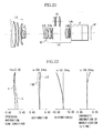
- FIG. 21 shows a cross-sectional view of the zoom lens at the wide-angle end according to Embodiment 4 (Numerical Example 4) of the present invention.
- FIG. 27 shows a cross-sectional view of a zoom lens at the wide-angle end according to Embodiment 5 (Numerical Example 5) of the present invention
- a reference character f denotes a focal length.
- the object distance refers to the distance measured from the image surface.
- FIGS. 33 and 34 show diagrams illustrating arrangements of paraxial refractive powers in the zoom lens according to Embodiments 4 and 5, wherein FIG. 33 shows a conceptual diagram illustrating in a case where the third lens unit has a negative refractive power and FIG. 34 shows a conceptual diagram illustrating in a case where the third lens unit has a positive refractive power.
- the zoom lens according to the respective embodiment is an image-taking optical system used for a image-taking system such as a video camera, a digital still camera, etc. to be described later, and in the cross-sectional views thereof, the left side is an object side (front side) and the right side is an image side (rear side).
- the zoom lens according to Embodiments 4 and 5 comprises a first lens unit L1 having a positive refractive power (optical power, that is, the reciprocal of the focal length), a second lens unit L2 having a negative refractive power, a third lens unit L3 having a positive or negative refractive power, and a fourth lens unit L4 having a positive refractive power, in order from the object side to the image side. Further, during the zooming operation, the second lens unit L2 and the third lens unit L3 are moved on the optical axis.
- the fourth lens unit L4 comprises a 4a lens sub-unit L4a having a positive refractive power, a 4b lens sub-unit L4b having a positive refractive power, and a 4c lens sub-unit L4c having a negative refractive power, in order from the object side to the image side. And, the focusing operation is performed by moving the 4b lens sub-unit L4b on the optical axis. Further, when the image-forming magnification of the 4c lens sub-unit L4c is represented by ⁇ 4c, the following conditional expression is satisfied: 1 ⁇
- the maximum movable amount of the 4b lens sub-unit L4b is decreased, thereby reducing the size of the fourth lens unit L4.
- the focal length of the zoom lens at the telephoto end as being fT and the minimum object distance as being MOD.
- ⁇ skmax fT 2 /(MOD-fT)
- the second lens unit L2 is moved on the optical axis from the object side to the image side.
- the third lens unit L3 has a negative refractive power
- the third lens unit L3 is moved on the optical axis to the object side and then is moved to the image side.
- the third lens unit L3 when the third lens unit L3 has a positive refractive power, the third lens unit L3 is moved on the optical axis from the image side to the object side. In the mean time, the third lens unit goes through a zoom state where the image-forming magnification is -1 (in other words, passes through such a zoom position).
- reference characters W and T denote the zoom positions of the wide-angle end and the telephoto end, respectively, a reference character ⁇ denotes an object at infinity, and a reference character MOD denotes the minimum object distance.
- the zoom lens according to Embodiments 4 and 5 employs a rear focusing type in which the focusing operation is performed by moving the 4b lens sub-unit L4b on the optical axis.
- Lines 4b1 and 4b2 associated with the 4b lens sub-unit L4b denote moving tracks for correcting for the variation of image surface due to the zooming during the focusing operation performed for the object at infinity and the close range object.
- the 4b lens sub-unit L4b is moved toward the front side as shown by an arrow 4b3.
- the second lens unit L2 as the zoom variator lens unit and the third lens unit L3 as an image-surface variation compensating unit for correcting for variation of an image surface due to the zooming, that is, by making the focus lens unit independent from the imaging-point variation compensating unit, the second lens unit L2 and the third lens unit L3 can be driven with a driving mechanism such as a cam, etc. independently of the focus lens unit, thereby making the manual zoom operation possible.
- a driving mechanism such as a cam, etc. independently of the focus lens unit
- the zoom lens satisfies the following conditional expression: 1 ⁇
- the image-forming magnification of the whole system of the zoom lens at an arbitrary zoom position as being ⁇
- the image-forming magnification of the first lens unit L1 as being ⁇ 1
- a position on the optical axis of the first lens unit L1 as being x0
- the maximum movable amount ⁇ xmax of the 4b lens sub-unit L4b can be further decreased, thereby further reducing the size of the fourth lens unit L4.
- the auto focusing operation is performed with the 4b lens sub-unit L4b and the manual focusing operation is performed with the whole unit or a part of the first lens unit L1.
- the 4b lens sub-unit L4b as the auto focus unit performs the auto focusing operation.
- a focal depth D of the zoom lens is expressed by the following expression.
- D ⁇ F
- a position of a principal point of the first lens unit L1 as being x
- a position of the principal point of the first lens unit L1 when achieving the in-focus in response to the object at infinity as being x0
- the combined image-forming magnification of the second lens unit L2 through the fourth lens unit L4 as being ⁇ 234.
- the displacement amount ⁇ sk of the image-forming position due to movement of the first lens unit L1 is expressed by the following expression.
- ⁇ sk (x-x0) ⁇ ( ⁇ 234) 2 Therefore, when Expression (36) is satisfied, the first lens unit L1 can be considered as achieving the in-focus in response to the object at infinity within the focal depth.
- an image-size conversion optical system sh which can be inserted into and removed from the optical path of the zoom lens, is provided closer to the object side than the 4b lens sub-unit L4b in the fourth lens unit L4.
- a conversion magnification of the image-size conversion optical system sh is represented by ⁇ sh, the following conditional expression is satisfied: ⁇ sh ⁇ 1
- the maximum movable amount of the 4b lens sub-unit L4b is defined as shmax in a state where the image-size conversion optical system sh is inserted into the optical path and the maximum movable amount of the 4b lens sub-unit L4b is defined as smax in a state where the image-size conversion optical system sh is not inserted into the optical path. Then, the following conditional expression is satisfied: 0.9 ⁇ shmax/( ⁇ sh 2 ⁇ smax) ⁇ 1.1
- the close range object is substantially invariable in the two states where the image-size conversion optical system sh is inserted and not inserted.
- the difference between the movable amounts is less than 10%, it has been actually known that there is no sense of discomfort.
- a reference character L1 denotes a focus lens unit (front lens unit) having a positive refractive power as a first lens unit.
- a reference character L2 denotes a variator lens unit (zoom lens unit) having a negative refractive power for zooming as a second lens unit and performs the zooming from the wide-angle end to the telephoto end with monotonous movement on the optical axis toward the image side.
- a reference character L3 denotes a compensator lens unit (image-surface variation compensating unit) having a negative refractive power as a third lens unit and is nonlinearly moved on the optical axis along a convex track toward the object side so as to correct for the variation of image surface due to the zooming.
- the variator lens unit L2 and the compensator lens unit L3 constitute a zoom system.
- a reference character SP denotes an aperture stop
- a reference character L4 denotes a relay lens unit having'a positive refractive power as a fourth lens unit and being fixed during the zooming operation.
- the fourth lens unit L4 has three lens sub-units L4a, L4b, and L4c.
- a reference character P denotes an optical element such as a color-separating prism, an optical prism, etc. and is shown as a glass block in the figure.
- a reference character IP denotes an image surface.
- an image-taking plane of a solid-state image pickup device such as a CCD sensor, a CMOS sensor, etc. is disposed on the image surface IP and when the zoom lens is used for an image-taking optical system of a silver-halide film camera, a film plane is disposed on the image surface IP.
- reference characters e and g denote the e line and g line, respectively
- reference characters ⁇ M and ⁇ S denote a meridional image surface and a sagittal image surface, respectively
- a chromatic aberration of magnification is specified by the g line.
- the fourth lens unit L4 has a positive refractive power as a whole and comprises a 4a lens sub-unit L4a having a positive refractive power, a 4b lens sub-unit L4b having a positive refractive power, and a 4c lens sub-unit L4c having a negative refractive power, in order from the object side to the image side.
- the 4b lens sub-unit L4b is a focus lens unit and is moved on the optical axis to the object side when performing the focusing operation to a close range object from an object at infinity.
- the 4b lens sub-unit L4b is driven using a known auto focusing mechanism.
- the maximum movable amount ⁇ xmax of the 4b lens sub-unit L4b from an object at infinity to the close range object during the focusing operation is -12.4 mm with the movement amount toward the image side set to be positive.
- the second lens unit L2 is used as a zoom lens unit having a negative refractive power and the third lens unit L3 is used as an image-surface variation compensating unit having a negative refractive power, so that the focus lens unit (4b lens sub-unit) L4b is provided separately from the image-surface variation compensating unit L3.
- the second lens unit L2 and the third lens unit L3 are movable independently of the focus lens unit L4b with a driving mechanism such as a cam, etc., it is possible to perform the manual zoom operation.
- the image-forming magnification ⁇ 4b of the 4b lens sub-unit L4b in the present embodiment is 0.179 and satisfies Expression (a).
- the manual focusing operation and the auto focusing operation become compatible.
- the whole unit or a part of the fourth lens unit L4 By moving the whole unit or a part of the fourth lens unit L4 on the optical axis, it is possible to make the flange back adjustment which is necessary for the zoom lens with a lens interchangeable manual focusing type.
- the auto focusing operation is performed with movement of the 4b lens sub-unit L4b as the auto focus unit.
- Table 8 gives an F number Fno, a focal depth D, a combined image-forming magnification ⁇ 234 of the second lens unit L2 through the fourth lens unit L4, and a difference
- the minimum diameter of a confusion circle ⁇ is set to 0.021 mm.
- the focal length of the whole system becomes 0.83 times in a state where the image-size conversion optical system sh is inserted into the optical path
- the maximum movable amount ⁇ shmax of the 4b lens sub-unit L4b during the focusing operation becomes -8.3 mm when the close range object is placed at 1 m
- the focal length becomes 0.67 times in a state where the image-size conversion optical system sh is not inserted into the optical path.
- Expression (35) is satisfied, so that the distance from the close range object is substantially invariable in the two states where the image-size conversion optical system sh is inserted and not inserted into the optical path. If a difference between the movable amounts is less than 10%, it has been actually known that there is no sense of discomfort.
- a reference character L1 denotes a focus lens unit (front lens unit) having a positive refractive power as a first lens unit.
- a reference character L2 denotes a variator lens unit having a negative refractive power for varying magnification as a second lens unit and performs zooming from the wide-angle end to the telephoto end with monotonous movement on the optical axis toward the image side.
- a reference character L3 denotes a compensator lens unit having a positive refractive power as a third lens unit and is monotonously and nonlinearly moved on the optical axis toward the object side so as to correct for the variation of image surface due to the zooming.
- the variator lens unit L2 and the compensator lens unit L3 constitute a zoom system.
- a reference character SP denotes an aperture stop
- a reference character L4 denotes a relay lens unit having a positive refractive power as a fourth lens unit and being fixed (not moved) during the zooming.
- the relay lens unit L4 has three lens sub-units L4a, L4b, and L4c.
- a reference character P denotes an optical element such as a color-separating prism, an optical filter, etc. and is shown as a glass block in the figure.
- the fourth lens unit L4 has a positive refractive power as a whole and comprises a 4a lens sub-unit L4a having a negative refractive power, a 4b lens sub-unit L4b having a positive refractive power, and a 4c lens sub-unit L4c having a negative refractive power, in order from the object side to the image side.
- the 4b lens sub-unit L4b is a focus lens unit and is moved on the optical axis to the object side during the focusing operation from an object at infinity to a close range object.
- the maximum movable amount ⁇ xmax of the 4b lens sub-unit L4b from the object at infinity to the close range object during the focusing operation is -13.1 mm with the movement amount toward the image side set to be positive.
- the second lens unit L2 is used as a zoom lens unit having a negative refractive power and the third lens unit L3 is used as an image-point variation compensating unit having a positive refractive power, so that the focus lens unit (the 4b lens sub-unit L4b) is provided separately from the image-point variation compensating unit L3.
- the second lens unit L2 and the third lens unit L3 are movable independently of the 4b lens sub-unit L4b with a driving mechanism such as a cam, etc., it is possible to make the zooming by manual operation.
- the image-forming magnification ⁇ 4b of the 4b lens sub-unit L4b in the present embodiment is 0.0707 and satisfies Expression (a).
- the manual focusing operation and auto focusing operation become compatible.
- the whole unit or a part of the fourth lens unit L4 on the optical axis it is possible to embody a flange back adjustment mechanism which is necessary for the zoom lens with a lens interchangeable manual focusing type.
- the auto focusing operation is performed with the 4b lens sub-unit L4b as the auto focus unit.
- Table 9 gives an F number Fno, a focal depth D, a combined image-forming magnification ⁇ 234 of the second lens unit L2 through the fourth lens unit L4, and a position difference
- the minimum diameter of a confusion circle ⁇ is set to 0.021 mm.
- a reference character i denotes the order of a surface from the object side
- a reference character ri denotes the radius of curvature of each surface
- a reference character di denotes the thickness of a medium or the air gap between the i-th surface and the (i+1)-th surface
- reference characters ni and vi denote the refractive index and the Abbe's number of the e line, respectively.
- Three surfaces closest to the image side in Numerical Example 4 and two surfaces closest to the image side in Numerical Example 5 are planes corresponding to a glass block.
- a reference character f denotes a focal length
- a reference character fno denotes an F number
- a reference character ⁇ denotes half the field angle.
- Table 12 gives various numerical values of Numerical Examples corresponding to Conditional Expressions described above.
- the zoom ratio is increased, the maximum movable amount of the focus lens unit is decreased, the size of the whole system of the lens is reduced, and a high optical performance is obtained over the whole object distance range.
- the zoom lens of Embodiments 4 and 5 by employing the rear focusing type in which the focus lens unit is provided closer to the image side than the zoom lens unit and by disposing the fixed lens unit having the absolute value of the image-forming magnification or conversion magnification larger than 1 at the image side of the focus lens unit, it is possible to repress the maximum movable amount of the focus lens unit during the focusing operation and thus to easily accomplish size reduction of the whole system of the lens with a high zooming ratio.
- FIG. 37 illustrates the structure of a video camera system using the zoom lens according to the above embodiments as an interchangeable lens system.
- a reference numeral 10 denotes a video camera body
- a reference numeral 11 denotes an image-taking optical system having the zoom lens according to the above embodiments
- a reference numeral 12 denotes a solid-state image-pickup element (photoelectric conversion element) such as a CCD sensor, a CMOS sensor, etc. for receiving an object image taken by the image-taking optical system 11.
- a reference numeral 13 denotes a memory for storing image data obtained with photoelectric conversion by the image-pickup element 12
- a reference numeral 14 denotes a finder for observing the object image displayed on a display element, which is not shown.
- the display element comprises a liquid crystal panel, etc. and displays the object image taken by the image-pickup element 12.
- a reference numeral 20 denotes a camera body
- a reference numeral 21 denotes an image-taking optical system having the zoom lens according to the above embodiments
- a reference numeral 22 denotes a solid-state image-pickup element (photoelectric conversion element) such as a CCD sensor, a CMOS sensor, etc. which is built in the camera body 20 and receives an object image formed by the image-taking optical system 21.
- a solid-state image-pickup element photoelectric conversion element
- a reference numeral 23 is a memory for storing image data obtained with photoelectric conversion by the image-pickup element 22 and a reference numeral 24 denotes a finder which has a liquid crystal display panel, etc. and is used to observe the object image taken by the image-pickup element 22.
- a reference numeral 30 denotes an interchangeable lens constructed as an image-taking optical system by the zoom lens according to the above embodiments and a reference numeral 40 denotes a video camera body which is mounted with the interchangeable lens 30.
- a reference numeral 42 denotes a solid-state image-pickup element (photoelectric conversion element) such as a CCD sensor, a CMOS sensor, etc. which is built in the video camera body 40 and receives an object image formed by the interchangeable lens 30.
- a reference numeral 43 denotes a memory for storing image data obtained with photoelectric conversion by the image-pickup element 42 and a reference numeral 44 denotes an electronic view-finder which has a liquid crystal display panel, etc. and is used to observe the object image taken by the image-pickup element 42.
- the zoom lens according to the above embodiments to the image-taking system such as a video camera, etc., it is possible to realize an image-taking system having a small size and high optical performance.
Landscapes
- Physics & Mathematics (AREA)
- General Physics & Mathematics (AREA)
- Optics & Photonics (AREA)
- Nonlinear Science (AREA)
- Lenses (AREA)
Applications Claiming Priority (4)
| Application Number | Priority Date | Filing Date | Title |
|---|---|---|---|
| JP2003376925A JP4508604B2 (ja) | 2003-11-06 | 2003-11-06 | ズームレンズ及びそれを有する撮像装置 |
| JP2003376925 | 2003-11-06 | ||
| JP2003386906 | 2003-11-17 | ||
| JP2003386906A JP2005148485A (ja) | 2003-11-17 | 2003-11-17 | ズームレンズ及びそれを有する撮像装置 |
Publications (3)
| Publication Number | Publication Date |
|---|---|
| EP1530071A2 true EP1530071A2 (de) | 2005-05-11 |
| EP1530071A3 EP1530071A3 (de) | 2006-11-08 |
| EP1530071B1 EP1530071B1 (de) | 2016-02-17 |
Family
ID=34436959
Family Applications (1)
| Application Number | Title | Priority Date | Filing Date |
|---|---|---|---|
| EP04256817.0A Expired - Lifetime EP1530071B1 (de) | 2003-11-06 | 2004-11-04 | Zoomlinse und Bildaufnahmevorrichtung |
Country Status (2)
| Country | Link |
|---|---|
| US (1) | US6987622B2 (de) |
| EP (1) | EP1530071B1 (de) |
Cited By (1)
| Publication number | Priority date | Publication date | Assignee | Title |
|---|---|---|---|---|
| CN106680982A (zh) * | 2015-11-10 | 2017-05-17 | 佳能株式会社 | 光学系统和包括该光学系统的摄像装置 |
Families Citing this family (14)
| Publication number | Priority date | Publication date | Assignee | Title |
|---|---|---|---|---|
| EP1530071B1 (de) * | 2003-11-06 | 2016-02-17 | Canon Kabushiki Kaisha | Zoomlinse und Bildaufnahmevorrichtung |
| JP2006201639A (ja) * | 2005-01-24 | 2006-08-03 | Citizen Electronics Co Ltd | カメラ用ズームユニット及びカメラ |
| JP5084437B2 (ja) * | 2007-10-19 | 2012-11-28 | キヤノン株式会社 | ズームレンズ及びそれを有する撮像装置 |
| US8194317B2 (en) * | 2008-04-02 | 2012-06-05 | Panasonic Corporation | Zoom lens system, interchangeable lens apparatus and camera system |
| JP2011123464A (ja) * | 2009-11-12 | 2011-06-23 | Olympus Imaging Corp | ズームレンズおよびそれを備えた撮像装置 |
| JP5656684B2 (ja) * | 2011-02-28 | 2015-01-21 | キヤノン株式会社 | ズームレンズ及びそれを有する撮像装置 |
| US20120320257A1 (en) * | 2011-06-17 | 2012-12-20 | Gal Shabtay | Auto-focus actuator for field curvature correction of zoom lenses |
| JP5870786B2 (ja) * | 2012-03-19 | 2016-03-01 | ソニー株式会社 | ズームレンズおよび撮像装置 |
| JP5961074B2 (ja) * | 2012-08-17 | 2016-08-02 | キヤノン株式会社 | ズームレンズ及びそれを有する撮像装置 |
| JP6331124B2 (ja) * | 2014-03-11 | 2018-05-30 | 株式会社リコー | ズームレンズ、撮像装置および監視用ビデオカメラ |
| JP6527328B2 (ja) * | 2014-12-26 | 2019-06-05 | キヤノン株式会社 | ズームレンズ及びそれを有する撮像装置 |
| WO2016121379A1 (ja) * | 2015-01-29 | 2016-08-04 | キヤノン株式会社 | レンズ装置および画像投射装置 |
| US11412041B2 (en) | 2018-06-25 | 2022-08-09 | International Business Machines Corporation | Automatic intervention of global coordinator |
| WO2020174761A1 (ja) | 2019-02-27 | 2020-09-03 | パナソニックIpマネジメント株式会社 | 交換レンズ、画像投写装置および撮像装置 |
Family Cites Families (33)
| Publication number | Priority date | Publication date | Assignee | Title |
|---|---|---|---|---|
| JPS58129404A (ja) * | 1982-01-27 | 1983-08-02 | Minolta Camera Co Ltd | 手動及び自動フオ−カシングの可能なズ−ムレンズ系 |
| JPS5963314U (ja) | 1982-10-19 | 1984-04-26 | 株式会社三協精機製作所 | ズ−ムレンズ |
| JPS6051813A (ja) * | 1983-08-31 | 1985-03-23 | Canon Inc | ズ−ムレンズ |
| US4701034A (en) * | 1984-03-02 | 1987-10-20 | Olympus Optical Co., Ltd. | Large aperture zoom lens system |
| JP2561637B2 (ja) | 1986-04-21 | 1996-12-11 | キヤノン株式会社 | 2つの合焦用レンズ群を有したズ−ムレンズ |
| JPH02118510A (ja) | 1988-10-27 | 1990-05-02 | Canon Inc | ズームレンズ |
| JPH02208618A (ja) | 1989-02-08 | 1990-08-20 | Canon Inc | ズームレンズ |
| JPH03123310A (ja) | 1989-10-07 | 1991-05-27 | Canon Inc | ズームレンズ |
| JPH03145615A (ja) | 1989-10-31 | 1991-06-20 | Canon Inc | ズームレンズ |
| JPH04138407A (ja) | 1990-09-29 | 1992-05-12 | Canon Inc | ズームレンズ |
| JPH05215967A (ja) | 1992-02-04 | 1993-08-27 | Konica Corp | 正屈折力の固定群を有する広角高変倍ズームレンズ |
| JP3161258B2 (ja) | 1994-11-15 | 2001-04-25 | キヤノン株式会社 | リヤーフォーカス式のズームレンズ |
| JP3278324B2 (ja) * | 1995-06-29 | 2002-04-30 | 富士写真光機株式会社 | ズームレンズ |
| JPH1062686A (ja) * | 1996-08-19 | 1998-03-06 | Fuji Photo Optical Co Ltd | インナーフォーカシングタイプのズームレンズ |
| JPH10170827A (ja) * | 1996-12-11 | 1998-06-26 | Fuji Photo Optical Co Ltd | ズームレンズ |
| JP3445095B2 (ja) * | 1997-04-01 | 2003-09-08 | キヤノン株式会社 | ズームレンズ及びそれを有するカメラ |
| US6055114A (en) * | 1997-06-18 | 2000-04-25 | Nikon Corporation | Zoom lens optical system |
| JP3849129B2 (ja) * | 1997-08-18 | 2006-11-22 | 株式会社ニコン | ズームレンズ |
| JP3824190B2 (ja) * | 1997-11-05 | 2006-09-20 | フジノン株式会社 | 広角ズームレンズ |
| US6002527A (en) * | 1998-02-11 | 1999-12-14 | Nikon Corporation | Compact high-zoom-ratio zoom lens |
| JP3962481B2 (ja) | 1998-04-23 | 2007-08-22 | キヤノン株式会社 | ズームレンズ及びそれを用いた光学機器 |
| JP3486560B2 (ja) * | 1998-10-14 | 2004-01-13 | キヤノン株式会社 | ズームレンズ |
| JP2000267003A (ja) * | 1999-03-12 | 2000-09-29 | Fuji Photo Optical Co Ltd | ズームレンズ |
| US6545818B2 (en) * | 1999-05-10 | 2003-04-08 | Canon Kabushiki Kaisha | Zoom lens and camera system |
| JP2001021803A (ja) | 1999-07-05 | 2001-01-26 | Sony Corp | ズームレンズ |
| JP2001194586A (ja) * | 2000-01-07 | 2001-07-19 | Canon Inc | ズームレンズ及びそれを用いた撮影装置 |
| JP4502341B2 (ja) * | 2000-02-16 | 2010-07-14 | フジノン株式会社 | ズームレンズ |
| JP2001343583A (ja) | 2000-05-31 | 2001-12-14 | Matsushita Electric Ind Co Ltd | ズームレンズ及びそれを用いたビデオカメラ |
| US6580564B2 (en) * | 2001-03-27 | 2003-06-17 | Fuji Photo Optical Co., Ltd. | Wide-angle zoom lens and projection-type display unit using it |
| JP4890703B2 (ja) * | 2001-09-27 | 2012-03-07 | 富士フイルム株式会社 | ズームレンズ |
| JP4234957B2 (ja) * | 2001-10-30 | 2009-03-04 | 株式会社リコー | ズームレンズ、撮像装置および携帯情報端末システム |
| US6985303B2 (en) * | 2003-05-08 | 2006-01-10 | Fujinon Corporation | Rear focus zoom lens |
| EP1530071B1 (de) * | 2003-11-06 | 2016-02-17 | Canon Kabushiki Kaisha | Zoomlinse und Bildaufnahmevorrichtung |
-
2004
- 2004-11-04 EP EP04256817.0A patent/EP1530071B1/de not_active Expired - Lifetime
- 2004-11-04 US US10/980,342 patent/US6987622B2/en not_active Expired - Fee Related
Non-Patent Citations (1)
| Title |
|---|
| None |
Cited By (2)
| Publication number | Priority date | Publication date | Assignee | Title |
|---|---|---|---|---|
| CN106680982A (zh) * | 2015-11-10 | 2017-05-17 | 佳能株式会社 | 光学系统和包括该光学系统的摄像装置 |
| US10539785B2 (en) | 2015-11-10 | 2020-01-21 | Canon Kabushiki Kaisha | Optical system and image pickup apparatus including the same |
Also Published As
| Publication number | Publication date |
|---|---|
| US6987622B2 (en) | 2006-01-17 |
| EP1530071A3 (de) | 2006-11-08 |
| US20050122595A1 (en) | 2005-06-09 |
| EP1530071B1 (de) | 2016-02-17 |
Similar Documents
| Publication | Publication Date | Title |
|---|---|---|
| US8482861B2 (en) | Zoom lens and image pickup apparatus equipped with zoom lens | |
| JP5871630B2 (ja) | ズームレンズ及びそれを有する撮像装置 | |
| US9081170B2 (en) | Zoom lens and image pickup apparatus including the same | |
| US7995286B2 (en) | Zoom lens and image pickup apparatus including the same | |
| US8437090B2 (en) | Zoom lens and image pickup apparatus including the same | |
| JP4976867B2 (ja) | ズームレンズ及びそれを有する撮像装置 | |
| US8264779B2 (en) | Zoom lens and image pickup apparatus including same | |
| US8493666B2 (en) | Zoom lens and image pickup apparatus with zoom lens | |
| US8873169B2 (en) | Zoom lens and image pickup apparatus using the same | |
| US8792181B2 (en) | Zoom lens and image pickup apparatus including the same | |
| JP2010060612A (ja) | ズームレンズ及びそれを有する撮像装置 | |
| US8405916B2 (en) | Zoom lens and image pickup apparatus including the same | |
| JP5774055B2 (ja) | ズームレンズ及びそれを有する撮像装置 | |
| EP1530071A2 (de) | Zoomlinse und Bildaufnahmevorrichtung | |
| US12235421B2 (en) | Optical system, image pickup apparatus, and lens apparatus | |
| US12517333B2 (en) | Zoom lens and image pickup apparatus having the same | |
| JP4617111B2 (ja) | ズームレンズ及びそれを有する撮像装置 | |
| WO2006033280A1 (ja) | ズームレンズ系、撮像装置及びカメラ | |
| US6751029B2 (en) | Zoom lens image pickup apparatus | |
| US11194138B2 (en) | Zoom lens, image pickup apparatus, and image pickup system | |
| US8228614B2 (en) | Zoom lens and image pickup apparatus having the zoom lens | |
| US8351128B2 (en) | Zoom lens and image pickup apparatus using the same | |
| JP4411010B2 (ja) | ズームレンズ及びそれを用いた撮像機器 | |
| US10908400B2 (en) | Zoom lens, image pickup apparatus including the same, and control device for the same | |
| JP7566550B2 (ja) | ズームレンズ及びそれを有する撮像装置、撮像システム |
Legal Events
| Date | Code | Title | Description |
|---|---|---|---|
| PUAI | Public reference made under article 153(3) epc to a published international application that has entered the european phase |
Free format text: ORIGINAL CODE: 0009012 |
|
| AK | Designated contracting states |
Kind code of ref document: A2 Designated state(s): AT BE BG CH CY CZ DE DK EE ES FI FR GB GR HU IE IS IT LI LU MC NL PL PT RO SE SI SK TR |
|
| AX | Request for extension of the european patent |
Extension state: AL HR LT LV MK YU |
|
| RIC1 | Information provided on ipc code assigned before grant |
Ipc: G02B 15/173 20060101ALI20060228BHEP Ipc: G02B 15/00 20060101AFI20050318BHEP |
|
| PUAL | Search report despatched |
Free format text: ORIGINAL CODE: 0009013 |
|
| AK | Designated contracting states |
Kind code of ref document: A3 Designated state(s): AT BE BG CH CY CZ DE DK EE ES FI FR GB GR HU IE IS IT LI LU MC NL PL PT RO SE SI SK TR |
|
| AX | Request for extension of the european patent |
Extension state: AL HR LT LV MK YU |
|
| 17P | Request for examination filed |
Effective date: 20070508 |
|
| AKX | Designation fees paid |
Designated state(s): DE FR GB |
|
| 17Q | First examination report despatched |
Effective date: 20111114 |
|
| GRAP | Despatch of communication of intention to grant a patent |
Free format text: ORIGINAL CODE: EPIDOSNIGR1 |
|
| INTG | Intention to grant announced |
Effective date: 20150805 |
|
| GRAS | Grant fee paid |
Free format text: ORIGINAL CODE: EPIDOSNIGR3 |
|
| GRAA | (expected) grant |
Free format text: ORIGINAL CODE: 0009210 |
|
| AK | Designated contracting states |
Kind code of ref document: B1 Designated state(s): DE FR GB |
|
| REG | Reference to a national code |
Ref country code: GB Ref legal event code: FG4D |
|
| REG | Reference to a national code |
Ref country code: DE Ref legal event code: R096 Ref document number: 602004048634 Country of ref document: DE |
|
| REG | Reference to a national code |
Ref country code: DE Ref legal event code: R097 Ref document number: 602004048634 Country of ref document: DE |
|
| PLBE | No opposition filed within time limit |
Free format text: ORIGINAL CODE: 0009261 |
|
| STAA | Information on the status of an ep patent application or granted ep patent |
Free format text: STATUS: NO OPPOSITION FILED WITHIN TIME LIMIT |
|
| 26N | No opposition filed |
Effective date: 20161118 |
|
| PGFP | Annual fee paid to national office [announced via postgrant information from national office to epo] |
Ref country code: DE Payment date: 20161130 Year of fee payment: 13 |
|
| GBPC | Gb: european patent ceased through non-payment of renewal fee |
Effective date: 20161104 |
|
| REG | Reference to a national code |
Ref country code: FR Ref legal event code: ST Effective date: 20170731 |
|
| PG25 | Lapsed in a contracting state [announced via postgrant information from national office to epo] |
Ref country code: FR Free format text: LAPSE BECAUSE OF NON-PAYMENT OF DUE FEES Effective date: 20161130 |
|
| PG25 | Lapsed in a contracting state [announced via postgrant information from national office to epo] |
Ref country code: GB Free format text: LAPSE BECAUSE OF NON-PAYMENT OF DUE FEES Effective date: 20161104 |
|
| REG | Reference to a national code |
Ref country code: DE Ref legal event code: R119 Ref document number: 602004048634 Country of ref document: DE |
|
| PG25 | Lapsed in a contracting state [announced via postgrant information from national office to epo] |
Ref country code: DE Free format text: LAPSE BECAUSE OF NON-PAYMENT OF DUE FEES Effective date: 20180602 |