EP1528993B1 - Procede et systeme de securisation pour dispositif de deplacement monte dans un vehicule automobile - Google Patents
Procede et systeme de securisation pour dispositif de deplacement monte dans un vehicule automobile Download PDFInfo
- Publication number
- EP1528993B1 EP1528993B1 EP20030790710 EP03790710A EP1528993B1 EP 1528993 B1 EP1528993 B1 EP 1528993B1 EP 20030790710 EP20030790710 EP 20030790710 EP 03790710 A EP03790710 A EP 03790710A EP 1528993 B1 EP1528993 B1 EP 1528993B1
- Authority
- EP
- European Patent Office
- Prior art keywords
- control device
- tsg
- zsg
- potential
- central control
- Prior art date
- Legal status (The legal status is an assumption and is not a legal conclusion. Google has not performed a legal analysis and makes no representation as to the accuracy of the status listed.)
- Expired - Lifetime
Links
- 238000000034 method Methods 0.000 title claims abstract description 15
- 238000006073 displacement reaction Methods 0.000 title 1
- 101100154842 Danio rerio twsg1b gene Proteins 0.000 claims description 17
- 101000620814 Homo sapiens Ras and EF-hand domain-containing protein Proteins 0.000 claims description 17
- 101000772122 Homo sapiens Twisted gastrulation protein homolog 1 Proteins 0.000 claims description 17
- 101150028791 taf4 gene Proteins 0.000 claims description 17
- 230000000903 blocking effect Effects 0.000 claims description 11
- 238000011156 evaluation Methods 0.000 claims description 7
- 230000005226 mechanical processes and functions Effects 0.000 claims description 4
- 230000015556 catabolic process Effects 0.000 claims 2
- 238000013475 authorization Methods 0.000 claims 1
- 239000000470 constituent Substances 0.000 claims 1
- 230000005540 biological transmission Effects 0.000 description 11
- 238000004891 communication Methods 0.000 description 7
- 230000003071 parasitic effect Effects 0.000 description 6
- 238000000926 separation method Methods 0.000 description 6
- 239000004065 semiconductor Substances 0.000 description 5
- 238000011161 development Methods 0.000 description 4
- 230000018109 developmental process Effects 0.000 description 4
- 238000010586 diagram Methods 0.000 description 4
- 230000005669 field effect Effects 0.000 description 4
- 230000007257 malfunction Effects 0.000 description 3
- 150000001875 compounds Chemical class 0.000 description 2
- 230000007547 defect Effects 0.000 description 2
- 230000001419 dependent effect Effects 0.000 description 2
- 238000001514 detection method Methods 0.000 description 2
- 238000005516 engineering process Methods 0.000 description 2
- 239000007858 starting material Substances 0.000 description 2
- 101100314406 Saccharomyces cerevisiae (strain ATCC 204508 / S288c) TPS1 gene Proteins 0.000 description 1
- 230000004913 activation Effects 0.000 description 1
- 230000002457 bidirectional effect Effects 0.000 description 1
- 239000004020 conductor Substances 0.000 description 1
- 230000006378 damage Effects 0.000 description 1
- 230000002950 deficient Effects 0.000 description 1
- 238000003745 diagnosis Methods 0.000 description 1
- 238000001035 drying Methods 0.000 description 1
- 230000000694 effects Effects 0.000 description 1
- 238000002955 isolation Methods 0.000 description 1
- 230000000704 physical effect Effects 0.000 description 1
- 230000035945 sensitivity Effects 0.000 description 1
- 230000002123 temporal effect Effects 0.000 description 1
Images


Classifications
-
- E—FIXED CONSTRUCTIONS
- E05—LOCKS; KEYS; WINDOW OR DOOR FITTINGS; SAFES
- E05B—LOCKS; ACCESSORIES THEREFOR; HANDCUFFS
- E05B81/00—Power-actuated vehicle locks
- E05B81/54—Electrical circuits
- E05B81/80—Electrical circuits characterised by the power supply; Emergency power operation
-
- B—PERFORMING OPERATIONS; TRANSPORTING
- B60—VEHICLES IN GENERAL
- B60R—VEHICLES, VEHICLE FITTINGS, OR VEHICLE PARTS, NOT OTHERWISE PROVIDED FOR
- B60R25/00—Fittings or systems for preventing or indicating unauthorised use or theft of vehicles
-
- E—FIXED CONSTRUCTIONS
- E05—LOCKS; KEYS; WINDOW OR DOOR FITTINGS; SAFES
- E05B—LOCKS; ACCESSORIES THEREFOR; HANDCUFFS
- E05B77/00—Vehicle locks characterised by special functions or purposes
- E05B77/02—Vehicle locks characterised by special functions or purposes for accident situations
-
- E—FIXED CONSTRUCTIONS
- E05—LOCKS; KEYS; WINDOW OR DOOR FITTINGS; SAFES
- E05B—LOCKS; ACCESSORIES THEREFOR; HANDCUFFS
- E05B77/00—Vehicle locks characterised by special functions or purposes
- E05B77/46—Locking several wings simultaneously
- E05B77/48—Locking several wings simultaneously by electrical means
-
- E—FIXED CONSTRUCTIONS
- E05—LOCKS; KEYS; WINDOW OR DOOR FITTINGS; SAFES
- E05B—LOCKS; ACCESSORIES THEREFOR; HANDCUFFS
- E05B81/00—Power-actuated vehicle locks
- E05B81/54—Electrical circuits
-
- E—FIXED CONSTRUCTIONS
- E05—LOCKS; KEYS; WINDOW OR DOOR FITTINGS; SAFES
- E05F—DEVICES FOR MOVING WINGS INTO OPEN OR CLOSED POSITION; CHECKS FOR WINGS; WING FITTINGS NOT OTHERWISE PROVIDED FOR, CONCERNED WITH THE FUNCTIONING OF THE WING
- E05F15/00—Power-operated mechanisms for wings
- E05F15/40—Safety devices, e.g. detection of obstructions or end positions
-
- E—FIXED CONSTRUCTIONS
- E05—LOCKS; KEYS; WINDOW OR DOOR FITTINGS; SAFES
- E05F—DEVICES FOR MOVING WINGS INTO OPEN OR CLOSED POSITION; CHECKS FOR WINGS; WING FITTINGS NOT OTHERWISE PROVIDED FOR, CONCERNED WITH THE FUNCTIONING OF THE WING
- E05F15/00—Power-operated mechanisms for wings
- E05F15/70—Power-operated mechanisms for wings with automatic actuation
- E05F15/72—Power-operated mechanisms for wings with automatic actuation responsive to emergency conditions, e.g. fire
-
- E—FIXED CONSTRUCTIONS
- E05—LOCKS; KEYS; WINDOW OR DOOR FITTINGS; SAFES
- E05Y—INDEXING SCHEME RELATING TO HINGES OR OTHER SUSPENSION DEVICES FOR DOORS, WINDOWS OR WINGS AND DEVICES FOR MOVING WINGS INTO OPEN OR CLOSED POSITION, CHECKS FOR WINGS AND WING FITTINGS NOT OTHERWISE PROVIDED FOR, CONCERNED WITH THE FUNCTIONING OF THE WING
- E05Y2400/00—Electronic control; Power supply; Power or signal transmission; User interfaces
- E05Y2400/10—Electronic control
- E05Y2400/50—Fault detection
- E05Y2400/504—Fault detection of control
-
- E—FIXED CONSTRUCTIONS
- E05—LOCKS; KEYS; WINDOW OR DOOR FITTINGS; SAFES
- E05Y—INDEXING SCHEME RELATING TO HINGES OR OTHER SUSPENSION DEVICES FOR DOORS, WINDOWS OR WINGS AND DEVICES FOR MOVING WINGS INTO OPEN OR CLOSED POSITION, CHECKS FOR WINGS AND WING FITTINGS NOT OTHERWISE PROVIDED FOR, CONCERNED WITH THE FUNCTIONING OF THE WING
- E05Y2800/00—Details, accessories and auxiliary operations not otherwise provided for
- E05Y2800/25—Emergency conditions
-
- E—FIXED CONSTRUCTIONS
- E05—LOCKS; KEYS; WINDOW OR DOOR FITTINGS; SAFES
- E05Y—INDEXING SCHEME RELATING TO HINGES OR OTHER SUSPENSION DEVICES FOR DOORS, WINDOWS OR WINGS AND DEVICES FOR MOVING WINGS INTO OPEN OR CLOSED POSITION, CHECKS FOR WINGS AND WING FITTINGS NOT OTHERWISE PROVIDED FOR, CONCERNED WITH THE FUNCTIONING OF THE WING
- E05Y2800/00—Details, accessories and auxiliary operations not otherwise provided for
- E05Y2800/40—Protection
- E05Y2800/428—Protection against water
-
- E—FIXED CONSTRUCTIONS
- E05—LOCKS; KEYS; WINDOW OR DOOR FITTINGS; SAFES
- E05Y—INDEXING SCHEME RELATING TO HINGES OR OTHER SUSPENSION DEVICES FOR DOORS, WINDOWS OR WINGS AND DEVICES FOR MOVING WINGS INTO OPEN OR CLOSED POSITION, CHECKS FOR WINGS AND WING FITTINGS NOT OTHERWISE PROVIDED FOR, CONCERNED WITH THE FUNCTIONING OF THE WING
- E05Y2900/00—Application of doors, windows, wings or fittings thereof
- E05Y2900/50—Application of doors, windows, wings or fittings thereof for vehicles
- E05Y2900/53—Application of doors, windows, wings or fittings thereof for vehicles characterised by the type of wing
- E05Y2900/55—Windows
-
- Y—GENERAL TAGGING OF NEW TECHNOLOGICAL DEVELOPMENTS; GENERAL TAGGING OF CROSS-SECTIONAL TECHNOLOGIES SPANNING OVER SEVERAL SECTIONS OF THE IPC; TECHNICAL SUBJECTS COVERED BY FORMER USPC CROSS-REFERENCE ART COLLECTIONS [XRACs] AND DIGESTS
- Y10—TECHNICAL SUBJECTS COVERED BY FORMER USPC
- Y10T—TECHNICAL SUBJECTS COVERED BY FORMER US CLASSIFICATION
- Y10T70/00—Locks
- Y10T70/60—Systems
- Y10T70/625—Operation and control
- Y10T70/65—Central control
-
- Y—GENERAL TAGGING OF NEW TECHNOLOGICAL DEVELOPMENTS; GENERAL TAGGING OF CROSS-SECTIONAL TECHNOLOGIES SPANNING OVER SEVERAL SECTIONS OF THE IPC; TECHNICAL SUBJECTS COVERED BY FORMER USPC CROSS-REFERENCE ART COLLECTIONS [XRACs] AND DIGESTS
- Y10—TECHNICAL SUBJECTS COVERED BY FORMER USPC
- Y10T—TECHNICAL SUBJECTS COVERED BY FORMER US CLASSIFICATION
- Y10T70/00—Locks
- Y10T70/60—Systems
- Y10T70/625—Operation and control
- Y10T70/675—Serially operable
Definitions
- the invention relates to a method and a safety system for a locking device of a motor vehicle according to the preamble of claim 1.
- the technical functionality of the adjustment systems depends on the functionality and reliability of the control units.
- Accident situations that lead to a partial destruction of the control electronics the risk of generating parasitic resistors that significantly reduce isolation between two tracks of the electronics of the door control unit.
- caused parasitic resistances can have values of a few hundred ohms. If this resistance arises between a drive connection of a circuit breaker and a fixed potential, in particular the battery voltage or the ground connection, this can lead to an undesired activation of the circuit breaker and consequently to an undesired adjustment of the adjustment device.
- the EP 1 044 857 A2 discloses an electronic Zündstartschalter- and steering wheel lock device for a motor vehicle having an ignition starter unit and a steering wheel lock unit, which are coupled together. If the vehicle engine is to be started via the ignition starter unit, it is first queried whether the steering wheel locking unit is in an unlocking state. Starting the engine is only released if this is the case.
- the EP 1 060 922 A1 discloses a circuit for controlling power windows, sliding roofs or door locks in motor vehicles, in which a drive of a power driver for actuation is only possible when a control switch is actuated and a switching element is connected.
- the invention has for its object to provide a method and a system for securing a locking device of a motor vehicle, which allows the opening of the locking device in case of failure of parts of the system and at the same time reduces the risk of automatic actuation in an undesirable state or manual malfunction ,
- a security system for a locking device of a motor vehicle wherein a control unit, which is part of the security system, at least one circuit breaker for controlling an electromechanical unit in the state "locks”, also called “safe”, and which additionally influenced by a central control unit is.
- This locked state differs from the locked states “unlocked” and “locked” of the closing device of the vehicle door.
- the motor vehicle door can be opened manually both from the outside and from the motor vehicle inside or the motor vehicle door can be opened automatically by means of a motor drive.
- the electromechanical units of the motor vehicle are placed in the state "locks". In the state "locks" all mechanical functions of the electromechanical unit are disabled, so that the vehicle door with the utility tool or from the vehicle interior is no longer open manually by the operation of mechanical components of the electromechanical unit.
- electromechanical unit which causes at least the states “unlocked”, “locked” and “locking” by the supply of electrical energy by means of mechanical adjustments.
- the states described may in principle be different for the respective motor vehicle doors or also for the tailgate of the motor vehicle.
- the states of all closing units of an automobile are preferably matched to one another by the central control unit by means of serial data protocols.
- a central control unit which has signal connections, in particular a serial bus connection, to the control devices of the respective door of the motor vehicle.
- signal connections enable data transmission to bring about the desired states in that the electromechanical unit can be actuated by the central control device via the signal connections.
- the signal connections enable data transmission for the transmission of desired states from the central control device to the respective control devices for controlling the local closing device.
- the data transmission is a signal assigned to the respective state, a voltage or binary data. More complex links enable the reliability of the transmission and the transmission of commands, status data and / or diagnostic data of the electromechanical unit or controls to be improved.
- the door control unit is connected to the central control unit via an independent of the signal connections electrical line connection.
- the signals or signals transmitted via the signal connections do not interfere with this independent electrical line connection.
- a particularly expedient and simple embodiment of the invention provides that an independent conductor electrically isolated from the signal connections, is used as an independent electrical line connection.
- this independent electrical line connection is a potential of a drive terminal of the aforementioned circuit breaker for energizing the electromechanical unit or a power terminal of the control unit, which is connectable to the electromechanical unit, controllable by the central control unit.
- the control is preferably carried out directly by the drive terminal or the power terminal is electrically connected directly to the central control unit via the independent electrical line connection.
- the potential of the relevant terminal could also be indirectly controlled by the central control unit by interposing a further logic element, for example a switching transistor, between the independent electrical line and the relevant terminal.
- the central control unit releases the control of the electromagnetic unit in the direction of "locks" only if the functionality of the serial data transmission is ensured via the signal connection, which can be done for example by a continuous status query of all controllers involved and the central control unit ,
- the central control device advantageously has an evaluation device which is used to control the power connection is formed as a function of a state or an emergency operation of the signal connections.
- this evaluation device cyclically queries the nodes of a bus system of the signal connections in order to check their functionality and the functionality of the signal connections.
- additional vehicle states, in particular the ignition state are evaluated.
- a switched off ignition is a further condition for controlling the potential of the control connection.
- At least one condition is not met, for example, the failure of the serial data protocol due to physical effects in the event of a crash, the release condition is not met, ie this is reset, so that the potential is not controlled on the independent electrical line connection by the central control unit.
- An advantageous embodiment of the invention provides that the potential for controlling this independent electrical line connection can be switched to control.
- the output of the central control unit for this switching operation on a low-impedance output the sensitivity of this independent electrical line connection to susceptible to interference sensitive, significantly reduced.
- Such a low-impedance output is realized, for example, by the use of switching transistors which, in addition to the connection to the independent electrical line connection, have a further connection to a current or voltage source, for example to the battery voltage Ub or to ground.
- the switching of the battery voltage or of the ground connection offers the possibility of transmitting the drive energy for the electromechanical unit at least for one adjustment direction via this independent electrical line connection.
- the central control unit has at least one switch for switching at least two different potentials. These potentials are, for example, the named ground potential or the battery voltage potential. If, on the other hand, a digital evaluation of the potential is preferred, a logic level, for example a level of 5 volts, can also serve as one of the two different potentials. By means of this switching of the two potentials is avoided that in a time state, a high-impedance output of the Central control unit leads to an undefined potential on the independent electrical line connection.
- the control of the potential by the central control unit and a control by the logic of the control unit are logically AND linked in a particularly advantageous embodiment of the invention for controlling the state "locks".
- the logic of the door control unit is for example a built-in door control unit microcontroller, which in turn can be connected via one of the signal connections to the central control unit.
- This logical AND operation produces a backup redundancy which further reduces the influence of parasitic resistances.
- it can be checked by checking the input states of the logical AND operation, whether the control unit of the door and the central control unit are in normal operation.
- An advantageous embodiment of this embodiment of the invention provides that form a series circuit for logical AND operation of the switch of the central control unit and a switch of the logic of the door control unit.
- the switches are preferably mechanical switches, in particular switching transistors, which in turn have a control connection.
- a first sub-variant of this embodiment of the invention provides that both switches are directly electrically connected to each other.
- the second sub-variant of this embodiment provides that both switches are connected to each other via a further element in particular via at least one terminal of the circuit breaker and the power terminal of the door control unit.
- the potential for driving the power switch between the ground potential and a drive potential, which may be less than or equal to the battery potential, switchable.
- each local control unit for controlling the electromechanical unit in each local control unit for controlling the electromechanical unit, a preferably permanent plausibility check, in which the release potential of the independent electrical line connection is switched only when the conditions "ignition from "and” undisturbed signal connections "are met.
- a preferred embodiment of the invention provides that the compounds are part of a bus system.
- This bus system is preferably a CAN bus system, that allows a connection with the central control unit and other devices of the motor vehicle. If at least one bidirectional connection, for example that of a CAN bus used, a transmission of status data between the devices of the motor vehicle is possible. In addition to the status data, further information about an operating mode, for example an emergency operation during an accident situation or a defect of the devices and a normal operation can be transmitted.
- Another embodiment of this development also allows a transmission of diagnostic data via the CAN bus system, which log the current reliability of individual elements of the security system, in particular the reliability of the potentials or the independent electrical line connection to the central control unit.
- control unit has a microcontroller.
- this microcontroller for example, a logic that allows the logical AND logic with the control of the central control unit.
- this microcontroller is used to control and calculate further operations of the functional elements of the motor vehicle door.
- This microcontroller is also connected to the circuit breaker via its drive connection for driving.
- an output PIN of the microcontroller can be connected directly to a discrete power switch in the form of a power transistor or a relay.
- an indirect wiring via a further logic of the control unit of the door or via a logic of the central control unit is also possible.
- the connection via a driver transistor for energizing the relay coil may be advantageous.
- the microcontroller can be integrated together with the power switch on a semiconductor chip as so-called smart power technology.
- the microcontroller of the control unit is operatively connected to the independent electrical line connection for evaluation.
- This active connection enables the detection of states and malfunctions of the line connection or of the transmitted signals or potentials. These malfunctions can be evaluated by the controller, or alternatively in an advantageous embodiment of this embodiment of the invention it is provided that the microcontroller of the controller via one of the signal connections a status of the potential of the drive terminal of the line switch or the state of the electromechanical unit to the Central control unit transmits.
- an evaluation of the detected states and functionalities by the central control unit is possible by this evaluates all detected by the control unit temporal changes and registered by a plausibility check deviation from a normal operation and possibly starts an emergency operation. In this emergency operation, for example, following a release to control the electromechanical unit is changed in the direction "locks".
- a window lifter drive of the motor vehicle door can additionally be released in the direction "closing" via the independent electrical line connection.
- a method for securing this adjusting device of a motor vehicle can be used particularly advantageously.
- the security system set out above or a modified security system can be used.
- the functionality of a central control unit and its compounds is evaluated.
- a characterizing parameter is evaluated. This parameter is, for example, the switching state of the ignition of the motor vehicle, so that a "lock" of the motor vehicle should not take place when the ignition is turned on.
- a potential for controlling the lock is switched to an independent of the signal connections electrical line connection.
- a control command is transmitted via one of the signal connections of the central control unit to a control unit. If an error-free operation of the devices and the signal connection is detected by the evaluation, is energized by a circuit breaker of the control unit of the door by means of the potential of an electromechanical unit of the castle and the lock in the state "locks".
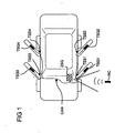
- FIG. 1 a motor vehicle is shown schematically.
- this motor vehicle has a central control unit ZSG, which can be controlled by radio, or optically by means of a remote control RC, for example a motor vehicle key.
- This central control unit ZSG is connected via a bus system CAN with door control units TSG 1, TSG 2, TSG 3 and TSG 4.
- the door control units TSG 1, TSG 2, TSG 3 and TSG 4 are arranged in the four doors of the motor vehicle.
- the connections of the bus communication structure CAN are routed from the motor vehicle interior via a respective door separation point TSS 1, TSS 2, TSS 3 and TSS 4 into the motor vehicle doors and are connected there to the door control devices TSG 1, TSG 2, TSG 3 and TSG 4.
- FIG. 2 A block diagram of the security system is in FIG. 2 shown.
- a door control unit TSG which is connected via an interface TSS with the central control unit ZSG and the battery of the motor vehicle Bat.
- An analogous structure also results for the other door control devices of the motor vehicle.
- the battery Bat has two terminals Ub and GND for the battery voltage potential Ub and the ground terminal GND. Both connections are connected both to the central control unit ZSG and to the door control unit TSG.
- the central control unit ZSG has a microcontroller ⁇ C1 and a CAN bus interface CAN.
- the CAN bus interface CAN is connected via the CAN bus CAN via the door separation point TSS with the CAN bus interface CAN of the door control unit TSG.
- the central control unit has two Potential switch PS 1 and PS 2, wherein the first potential switch PS1 is connected to the battery voltage potential Ub and the control line.
- the second potential switch PS 2 is connected to the control line St and the ground GND.
- the door control unit TSG is in addition to the connection to the central control unit via the CAN bus system CAN and the independent electrical control line St and the supply line to the motor vehicle battery Bat connected to other functional units of the vehicle door.
- Two electromechanical adjusting drives M1 and M2 are connected to the door control unit TSG, which has power switches LS1 and LS2 for energizing the two drives M1 and M2.
- the first adjusting drive M1 is an adjusting drive of a motor vehicle lock, this adjusting drive M1 serving for locking and unlocking the motor vehicle door.
- the second electromechanical drive M2 serves the same lock to switch to the state "locks", a so-called safe state.
- this second power switch LS2 is connected by means of the control line directly to the central control unit.
- the second power switch and the first power switch LS1 are designed as mechanical power switches in the form of relays or the like or as semiconductor full or half bridges.
- the circuit breakers. LS1 and LS2 have several in FIG. 2 not shown control inputs. These control inputs are connected to the microcontroller ⁇ C2 of the door control unit TSG and the control line St or further input circuit.
- the central control unit subsequently switches the control line St by means of the potential switch PS1 to the operating voltage potential of the battery Bat Ub.
- the second potential switch PS2 which has previously connected the control line St to ground, is opened.
- the central control unit sends via the CAN bus CAN a signal in the door control unit TSG, which includes a command for energizing the second electromechanical drive unit M2.
- FIG. 3 illustrated circuit diagram is a section of the more specific embodiment of the illustrated FIG. 2 ,
- the door separation point TSS is shown with the laid by the door separation point TSS connections of the Central control unit ZSG for door control unit TSG.
- the connection here again is the control line St, the battery voltages Ub and the ground connection GND.
- a CAN bus system CAN is provided for communication between the door control unit and the central control unit.
- the door control unit TSG is in turn connected to the lock Sch a motor vehicle door via three Bestromungs effeten.
- the lock Sch the motor vehicle door is arranged in a wet space N of the vehicle door and sealed for this purpose against ingress of moisture.
- the door control unit TSG is arranged on the dry-room side T of the motor vehicle door and has no moisture protection adequate to the wet space.
- the microcontroller ⁇ C1 of the central control unit ZSG and the microcontroller of the door control unit TSG via transceiver circuits Trans 1 and Trans 2 are interconnected, the corresponding hardware for the CAN bus control available put.
- the microcontroller .mu.C1 of the central control unit is connected to a control terminal with a field effect transistor JFET, which enables a connection of the battery voltage Ub to the control line St.
- the microcontroller ⁇ C2 of the door control unit TSG has three outputs which are connected via resistors R1, R2 or R3 to driver transistors, in this case NPN bipolar transistors Q1, Q2 and Q3, respectively.
- the driver transistors Q1, Q2 and Q3 are respectively connected to a relay coil In1, ln2 and In3 of a relay RL1, RL2 and RL3, respectively, and the driver transistors Q1, Q2 and Q3 ground the terminals of the relay coils In1, In2 and In3.
- the other terminal of the relay coils In1 and INn2 is connected to the battery voltage Ub, whereas the relay coil In3 is connected to the second terminal to the control line St.
- This third relay RL3 is used to energize the second electromechanical drive unit M2 of the lock Sch in the direction of the lock state "Safe".
- the control line in order to switch the lock into the blocking state, the control line must be switched to battery voltage potential Ub by means of the field effect transistor JFET of the central control unit and at the same time the driver transistor Q3 must be connected through the microcontroller ⁇ C2 of the door control unit TSG via the third resistor R3. Accordingly, as a condition to operate the lock in the state "lock", by an AND operation on the driver transistor Q3 applied output voltage of the microcontroller ⁇ C2 with the switched field effect transistor JFET of the central control unit ZSG required.
- relay switches S1, S2 and S3 are provided for the actual energization of the drive units M1 and M2 of the lock Sch. These relay switches are connected on the one hand to the ground GND to the other with the battery voltage Ub.
- the relay switch S3 of the third relay RL3 can optionally be connected to the battery voltage Ub or to the control line St via a bridge, a so-called jumper Jp. If the relay switch S3 is additionally connected to the control line St, the second drive unit M2 of the lock Sch is energized via the control line St.
- relays RL1, RL2 and RL3 alternatively power semiconductors can be used, which can also be integrated into the microcontroller ⁇ C2 as smart power elements.
- the semiconductor power switches are designed as discrete elements, their driving is preferably carried out in antiphase, in order to obtain an in-phase noise voltage on the drive terminals of the discrete power switch when a parasitic resistance occurs, which does not cause unwanted switching of the power transistors. This is the case in particular because the parasitic resistors act in the same way on interconnects arranged parallel to one another and serve to drive these discrete power switches.
- FIGS. 4a and 4b is a process flow for securing a motor vehicle lock by means of a flowchart shown schematically.
- the central control unit ZSG receives the "safe" command, ie, the motor vehicle doors, in the "lock” state, for example via a remote control or the actuation of one of the locks by means of a motor vehicle key
- the central control unit can check, for example, at least the door control units TSG of the motor vehicle doors for functionality If a functionality of the CAN bus connection is given, in a third step the query for a CAN size of the motor vehicle, in this Embodiment according to the state of the engine ignition.
- the engine ignition by the ignition key or the like takes place in a fourth step of FIG. 4 a the application of a potential to an independent electrical line connection St.
- a safe control command transmitted to the door control units TSG.
- an error is indicated by the safety system in a sixth step.
- the error is logged in a file and made available for later error diagnosis.
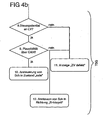
- FIG. 4b shows the second part of the method for securing by the security system, which runs in the door control unit TSG.
- the transmission of the safe control command via the CAN bus to the door control unit is checked in the door control unit TSG by its microcontroller ⁇ C1 the control potential of the control line St. If the control potential corresponds to the potential for blocking the motor vehicle door, a plausibility check of the overall system, in which, for example, the communication system and the functionality of the door control unit is checked, is additionally carried out in a ninth step.
- the lock Sch is activated in the state "Safe". If the control potential for controlling the second electromechanical unit M2 in the direction of blocking is unsuitable in step 8, an indication is given in step 11 about the defective state of the central locking ZV. Similarly, in the eleventh step, the display of a defect of the central locking ZV, if the plausibility check of the ninth step results in a negative result. In this case, in addition to the display in step eleven, the lock is actuated in a twelfth method step in the direction of unlocking in order to be sure that a person in the motor vehicle may leave the motor vehicle when the lock has already reached a locked state ,
- the detection of an error triggers a display of a critical condition in a vehicle display for the vehicle user, and the door locks are driven to the unlocked state.
- An end position in the "safe” is following by the lock mechanism only on the intermediate position “locked” possible, so that in case of failure two conditions must be met necessarily to bring from the state “unlocked” the vehicle door in the state "locked”.
Claims (15)
- Système de sécurisation d'un dispositif de fermeture pour verrouiller au moins une portière d'un véhicule automobile, avec- un dispositif de commande (TSG, TSG1, TSG2, TSG3, TSG4) lequel présente au moins un commutateur de puissance (LS1, LS2) pour commander le passage d'une unité électromécanique (M1, M2) à un état de « verrouillage », et- un appareil de commande central (ZSG), lequel présente des liaisons de signaux (CAN) vers le dispositif de commande (TSG, TSG1, TSG2, TSG3, TSG4) et d'autres dispositifs de commande du véhicule automobile, dans lequel l'une au moins unité électromécanique (M1, M2) pouvant être commandée grâce à l'appareil de commande central (ZSG) via les liaisons de signaux (CAN),caractérisé en ce
que- le dispositif de commande (TSG, TSG1, TSG2, TSG3, TSG4) est relié à l'appareil de commande central (ZSG) par l'intermédiaire d'une liaison câblée électrique (St) indépendante des liaisons de signaux (CAN), et en ce- qu'un potentiel (Ub, GND) d'une borne de commande du commutateur de puissance (LS1, LS2) du dispositif de commande (TSG, TSG1, TSG2, TSG3, TSG4) ou une borne de puissance du dispositif de commande (TSG, TSG1, TSG2, TSG3, TSG4) peut être commandé via la liaison câblée électrique indépendante (St) par l'appareil de commande central (ZSG),
sachant que l'appareil de commande central (ZSG) autorise, via la liaison câblée électrique indépendante (St), le dispositif de commande (TSG, TSG1, TSG2, TSG3, TSG4) à déclencher le passage de l'unité électromécanique (M1, M2) à l'état de « verrouillage » où toutes les fonctions mécaniques de l'unité électromécanique sont désactivées, et qu'un déclenchement pour le passage de l'unité électromécanique (M1, M2) à l'état de « verrouillage » n'est pas possible sans cette autorisation. - Système de sécurisation selon la revendication 1, caractérisé en ce que l'appareil de commande central (ZSG) présente une unité d'analyse (µC1), laquelle est réalisée pour la commande de la borne de puissance en fonction d'un état ou d'un régime de secours des liaisons de signaux (CAN), en particulier d'un système de bus (CAN).
- Système de sécurisation selon l'une quelconque des revendications précédentes, caractérisé en ce que, pour la commande, le potentiel (Ub, GND) peut être appliqué à la liaison câblée électrique indépendante (St).
- Système de sécurisation selon l'une quelconque des revendications précédentes, caractérisé en ce que l'appareil de commande central (ZSG) présente au moins un commutateur (PS1, PS2) pour commuter ou sectionner au moins deux potentiels distincts (Ub, GND).
- Système de sécurisation selon l'une quelconque des revendications précédentes, caractérisé en ce que, pour le déclenchement du passage à l'état de « verrouillage », la commande du potentiel (Ub, GND) grâce à l'appareil de commande central (ZSG) et une commande grâce à une logique (µC2) du dispositif de commande (TSG, TSG1, TSG2, TSG3, TSG4) sont reliées par une fonction logique ET.
- Système de sécurisation selon la revendication 5, caractérisé en ce que, pour la liaison grâce à la fonction logique ET, le commutateur (PS1, PS2) de l'appareil de commande central (ZSG) et un commutateur (Q1, Q2, Q3) de logique (µC2) du dispositif de commande (TSG, TSG1, TSG2, TSG3, TSG4) forment une connexion en série.
- Système de sécurisation selon l'une quelconque des revendications précédentes, caractérisé en ce que le potentiel pour la commande du commutateur de puissance (LS1, LS2) peut être commuté entre un potentiel de masse (GND) et un potentiel de commande (Ub), lequel est inférieur ou égal à un potentiel de batterie, en particulier pour couper la liaison câblée électrique indépendante (St) du potentiel de commande (Ub) et la connecter au potentiel de masse (GND).
- Système de sécurisation selon l'une quelconque des revendications précédente, caractérisé en ce que les liaisons de signaux (CAN) sont des éléments constitutifs d'un système de bus, en particulier d'un bus CAN (CAN).
- Système de sécurisation selon l'une quelconque des revendications précédentes, caractérisé en ce que le dispositif de commande (TSG, TSG1, TSG2, TSG3, TSG4) comporte un microcontrôleur (uC2), lequel est en liaison avec la borne de commande du commutateur de puissance (LS1, LS2) pour la commande de celui-ci.
- Système de sécurisation selon la revendication 9, caractérisé en ce que le microcontrôleur (µC2) du dispositif de commande (TSG, TSG1, TSG2, TSG3, TSG4) est en liaison active avec la liaison câblée électrique indépendante (St) pour l'analyse du potentiel actuel (Ub, GND).
- Système de sécurisation selon la revendication 10, caractérisé en ce que le microcontrôleur (µC2) du dispositif de commande (TSG, TSG1, TSG2, TSG3, TSG4) est réalisé pour la transmission d'un statut du potentiel (Ub, GND) de la borne de commande, du commutateur de puissance (LS1, LS2) ou de l'état de l'unité électromécanique (M1, M2), à l'appareil de commande central (ZSG) via l'une quelconque des liaisons de signaux (CAN).
- Système de sécurisation selon l'une quelconque des revendications précédentes, caractérisé en ce que le dispositif de commande (TSG, TSG1, TSG2, TSG3, TSG4) est disposé dans une portière de véhicule automobile, et en ce que l'appareil de commande central (ZSG) est disposé en-dehors de la portière du véhicule automobile, mais cependant à l'intérieur du véhicule automobile.
- Système de sécurisation selon l'une quelconque des revendications précédentes, caractérisé en ce qu'en guise de commutateur de puissance (LS1, LS2), on peut commander un relais (RL1, RL2, RL3), et en ce que la liaison câblée électrique indépendante (St) est raccordée à une borne d'une bobine de relais (In1, In2, In3).
- Procédé pour la sécurisation d'un dispositif de fermeture d'un véhicule automobile,dans lequel, pour commander une serrure d'un véhicule automobile à l'état de « verrouillage », dans lequel toutes les fonctions mécaniques de l'unité électromécanique sont désactivées,- la capacité de bon fonctionnement d'un appareil de commande central (ZSG) et de liaisons de signaux (CAN) associées est analysée,- des paramètres caractérisants de l'état de fonctionnement du véhicule automobile étant analysés,- un potentiel (Ub, GND) pour la commande de la serrure étant appliqué à une liaison câblée électrique indépendante (St) des liaisons de signaux (CAN),- une instruction de commande étant transmise via l'une quelconque des liaisons de signaux (CAN) de l'appareil de commande central (ZSG) à un dispositif de commande de portière (TSG, TSG1, TSG2, TSG3, TSG4), et- par l'intermédiaire d'un commutateur de puissance (LS1, LS2) du dispositif de commande (TSG, TSG1, TSG2, TSG3, TSG4), à l'aide du potentiel (Ub, GND), une unité électromécanique (M1, M2) de la serrure est alimentée en courant, lorsque l'analyse permet de détecter un fonctionnement sans erreur de l'appareil de commande central (ZSG) et des liaisons de signaux (CAN).
- Procédé selon la revendication 14, caractérisé en ce qu'une commande intempestive de la serrure du véhicule automobile à l'état de « verrouillage » est empêchée, et en ce que, en cas d'une défaillance, d'une perturbation ou d'un mode de secours déclenché d'un système de bus du véhicule automobile,- la défaillance ou la perturbation est détectée par un appareil de commande central (ZSG) du véhicule automobile et un mode de secours est en particulier déclenché ou bien par le dispositif de commande (TSG, TSG1, TSG2, TSG3, TSG4) transmettant une information concernant le déclenchement d'un mode de secours via le système de bus à l'attention de l'appareil de commande central (ZSG), et- l'appareil de commande central (ZSG) applique un potentiel de commande (Ub) à la liaison câblée (St) indépendante des liaisons de signaux (CAN) du système de bus, moyennant quoi l'on empêche un déclenchement du passage du dispositif de fermeture à l'état de « verrouillage » en fonction du potentiel de commande (Ub).
Applications Claiming Priority (3)
| Application Number | Priority Date | Filing Date | Title |
|---|---|---|---|
| DE10236106A DE10236106A1 (de) | 2002-08-07 | 2002-08-07 | Verfahren und Sicherungssystem für eine Verstelleinrichtung eines Kraftfahrzeugs |
| DE10236106 | 2002-08-07 | ||
| PCT/DE2003/002690 WO2004020258A1 (fr) | 2002-08-07 | 2003-08-06 | Procede et systeme de securisation pour dispositif de deplacement monte dans un vehicule automobile |
Publications (2)
| Publication Number | Publication Date |
|---|---|
| EP1528993A1 EP1528993A1 (fr) | 2005-05-11 |
| EP1528993B1 true EP1528993B1 (fr) | 2009-11-11 |
Family
ID=30469528
Family Applications (1)
| Application Number | Title | Priority Date | Filing Date |
|---|---|---|---|
| EP20030790710 Expired - Lifetime EP1528993B1 (fr) | 2002-08-07 | 2003-08-06 | Procede et systeme de securisation pour dispositif de deplacement monte dans un vehicule automobile |
Country Status (5)
| Country | Link |
|---|---|
| US (1) | US7550867B2 (fr) |
| EP (1) | EP1528993B1 (fr) |
| AT (1) | ATE448118T1 (fr) |
| DE (2) | DE10236106A1 (fr) |
| WO (1) | WO2004020258A1 (fr) |
Families Citing this family (16)
| Publication number | Priority date | Publication date | Assignee | Title |
|---|---|---|---|---|
| NZ529152A (en) * | 2003-10-23 | 2006-11-30 | Magna Ltd | Child safety lock system with remote proximity actuator mechanism |
| US20070058663A1 (en) * | 2005-08-25 | 2007-03-15 | Mcgee Phillip | Flexible collision detection serial bus transceiver apparatus and method |
| DE102006033767A1 (de) * | 2006-07-21 | 2008-01-24 | Bayerische Motoren Werke Ag | Türschloss für Kraftfahrzeuge |
| TWI448111B (zh) * | 2008-03-18 | 2014-08-01 | Icm Inc | Automobile detection and control integration device and method thereof |
| US11155236B2 (en) * | 2009-01-15 | 2021-10-26 | Ahern Rentals, Inc. | Method and a system for controlling and monitoring operation of a device |
| FI121465B (fi) | 2009-08-25 | 2010-11-30 | Kone Corp | Kuljetusjärjestelmä |
| CN102262400B (zh) * | 2010-05-24 | 2013-05-29 | 北京北广科技股份有限公司 | 基于can通信的步进电机驱动器的远程键控方法及装置 |
| DE102010063567A1 (de) * | 2010-12-20 | 2012-06-21 | Bayerische Motoren Werke Aktiengesellschaft | Anzeigesystem für ein Kraftfahrzeug |
| US8924087B2 (en) | 2012-05-15 | 2014-12-30 | GM Global Technology Operations LLC | Motor vehicle having a centralized door locking system |
| US20140379178A1 (en) * | 2013-06-24 | 2014-12-25 | Honeywell International Inc. | System and method for fine positioning of vtol stare point |
| US9802553B2 (en) * | 2013-08-12 | 2017-10-31 | Nissan North America, Inc. | Vehicle body structure |
| JP2015085739A (ja) * | 2013-10-29 | 2015-05-07 | アイシン精機株式会社 | 車両用開閉部材の制御装置及び制御方法 |
| US9618909B2 (en) | 2013-12-20 | 2017-04-11 | Thales Canada Inc | Safety assurance of multiple redundant systems |
| DE102018202784A1 (de) * | 2018-02-23 | 2019-08-29 | Brose Fahrzeugteile Gmbh & Co. Kommanditgesellschaft, Bamberg | Verfahren zur Zuweisung von Betriebsparametern an zur Steuerung einer Türbewegung vorgesehene lokale Steuereinheiten in einem Kraftfahrzeug |
| DE102018126830A1 (de) * | 2018-10-26 | 2020-04-30 | Bayerische Motoren Werke Aktiengesellschaft | Vorrichtung und Steuereinheit zur Automatisierung einer Zustandsänderung einer Fensterscheibe eines Fahrzeugs |
| DE102020123596A1 (de) | 2020-09-10 | 2022-03-10 | Kiekert Aktiengesellschaft | Aufstellvorrichtung für ein Kraftfahrzeugtürelement |
Family Cites Families (23)
| Publication number | Priority date | Publication date | Assignee | Title |
|---|---|---|---|---|
| DE4126375A1 (de) * | 1991-08-09 | 1993-02-11 | Bayerische Motoren Werke Ag | Steuervorrichtung in kraftfahrzeugen |
| DE4323813C2 (de) * | 1992-07-17 | 1999-02-18 | Mitsui Mining & Smelting Co | Fahrzeugtürverschlußvorrichtung mit Überverschlußmechanismus |
| DE4338707A1 (de) * | 1993-11-12 | 1995-05-18 | Bosch Gmbh Robert | Anordnung mit wenigstens zwei über Schnittstellen verbindbaren Teilnehmern |
| DE4404501C2 (de) * | 1994-02-12 | 2001-07-05 | Marquardt Gmbh | Elektronisches Türschließsystem |
| DE4427254B4 (de) * | 1994-07-30 | 2004-02-26 | Kiekert Ag | Verschlußsystem für ein Kraftfahrzeug |
| JP3702906B2 (ja) | 1995-05-30 | 2005-10-05 | ジヤトコ株式会社 | マイコン搭載車両の負荷駆動制御装置 |
| DE19547728C2 (de) * | 1995-12-20 | 2001-08-16 | Mannesmann Vdo Ag | Schaltungsanordnung mit einer elektrischen Stelleinrichtung |
| DE19613590C2 (de) * | 1996-04-04 | 2001-07-26 | Volkswagen Ag | Verfahren und Vorrichtung zur Steuerung einer Anzahl von untereinander kommunizierenden Aktuatoren |
| JP3783297B2 (ja) * | 1996-09-27 | 2006-06-07 | マツダ株式会社 | 車両のドアロック装置 |
| KR100355157B1 (ko) | 1997-04-02 | 2002-12-26 | 닛산 지도우샤 가부시키가이샤 | 차량용개폐장치제어회로 |
| DE19741438C5 (de) | 1997-09-19 | 2004-09-02 | Siemens Ag | Verfahren und Steuersystem zum Stillsetzen eines Kraftfahrzeugs |
| JP3846659B2 (ja) * | 1997-12-19 | 2006-11-15 | マツダ株式会社 | 車両用ドアロック制御装置 |
| US6430488B1 (en) | 1998-04-10 | 2002-08-06 | International Business Machines Corporation | Vehicle customization, restriction, and data logging |
| JP3597072B2 (ja) * | 1999-03-01 | 2004-12-02 | アルプス電気株式会社 | パワーウインド装置 |
| DE19916966C5 (de) | 1999-04-15 | 2006-09-21 | Daimlerchrysler Ag | Elektronische Zündstartschalter- und Lenkradverriegelungsvorrichtung |
| DE19928101C2 (de) * | 1999-06-19 | 2001-10-11 | Brose Fahrzeugteile | Verfahren zum Steuern fremdkraftbetriebener Fensterheber, Schiebedächer und/oder Schlösser in Kraftfahrzeugen |
| DE19946993A1 (de) | 1999-09-30 | 2001-04-19 | Infineon Technologies Ag | Schutzschaltung für ein zugriffsarbitriertes Bussystem-Netzwerk |
| ES2252085T3 (es) | 2000-01-08 | 2006-05-16 | LEOPOLD KOSTAL GMBH & CO. KG | Disposicion de circuito electrico para controlar el electromotor de un vehiculo automovil. |
| DE10000532A1 (de) * | 2000-01-08 | 2001-07-26 | Kostal Leopold Gmbh & Co Kg | Elektrische Schaltungsanordnung |
| JP4239417B2 (ja) * | 2000-07-10 | 2009-03-18 | トヨタ自動車株式会社 | 蓄熱装置付き内燃機関 |
| JP4389366B2 (ja) * | 2000-08-11 | 2009-12-24 | 株式会社デンソー | 電子制御装置 |
| DE10049616C1 (de) * | 2000-10-05 | 2002-04-18 | Behr Hella Thermocontrol Gmbh | Schaltungsanordnung zur Steuerung einer elektrischen Last in einem Kraftfahrzeug |
| DE10062548A1 (de) * | 2000-12-15 | 2002-06-20 | Daimler Chrysler Ag | Eletromotorischer Stellantrieb |
-
2002
- 2002-08-07 DE DE10236106A patent/DE10236106A1/de not_active Withdrawn
-
2003
- 2003-08-06 WO PCT/DE2003/002690 patent/WO2004020258A1/fr active Application Filing
- 2003-08-06 DE DE50312115T patent/DE50312115D1/de not_active Expired - Lifetime
- 2003-08-06 US US10/523,496 patent/US7550867B2/en not_active Expired - Fee Related
- 2003-08-06 AT AT03790710T patent/ATE448118T1/de not_active IP Right Cessation
- 2003-08-06 EP EP20030790710 patent/EP1528993B1/fr not_active Expired - Lifetime
Also Published As
| Publication number | Publication date |
|---|---|
| DE50312115D1 (de) | 2009-12-24 |
| DE10236106A1 (de) | 2004-02-19 |
| US20060108874A1 (en) | 2006-05-25 |
| US7550867B2 (en) | 2009-06-23 |
| WO2004020258A1 (fr) | 2004-03-11 |
| EP1528993A1 (fr) | 2005-05-11 |
| ATE448118T1 (de) | 2009-11-15 |
Similar Documents
| Publication | Publication Date | Title |
|---|---|---|
| EP1060922B1 (fr) | Circuit et procédé de commande de lève-vitre électrique, de toit coulissant, ou de serrure automatique pour portes pour véhicule automobile | |
| EP1528993B1 (fr) | Procede et systeme de securisation pour dispositif de deplacement monte dans un vehicule automobile | |
| EP1544388B1 (fr) | Véhicule automobile | |
| WO2013127382A2 (fr) | Fermeture de portière de véhicule à moteur | |
| EP1000823B1 (fr) | Dispositif de sécurité pour véhicule | |
| WO2009074323A2 (fr) | Concept de sécurité pour actionneur intelligent | |
| EP2336465A2 (fr) | Circuit et procédé de protection contre l'ouverture involontaire d'une porte de véhicule | |
| DE102018222408A1 (de) | Elektronisches Türschließsystem und Kraftfahrzeug | |
| EP0642959A1 (fr) | Dispositif antivol pour véhicule automobile | |
| DE102021115769B3 (de) | Verfahren zum Betreiben einer Steueranordnung | |
| DE10052316A1 (de) | Vorrichtung zur Ansteuerung einer elektrischen Sicherungseinrichtung für ein Kraftfahrzeug | |
| EP1713997A1 (fr) | Montage electrique | |
| EP2581277B1 (fr) | Dispositif pour un système de sécurité d'un véhicule automobile avec un système électronique conçu de manière autonome et indépendante par rapport au véhicule | |
| DE102006062315A1 (de) | Elektronische Lenkungsverriegelung mit einer zusätzlichen Entriegelungsmöglichkeit bei aktivem Sicherheitsabschaltsignal | |
| DE102005031382A1 (de) | Kraftfahrzeugschloss | |
| WO2001073696A1 (fr) | Dispositif avertisseur pour les usagers d'un vehicule | |
| EP1273482B1 (fr) | Dispositif de commande pour sous-ensembles électriques dans un véhicule | |
| DE10323504A1 (de) | Vorrichtung und Verfahren zur Diebstahlsicherung eines Kraftfahrzeuges | |
| DE10226252B4 (de) | Schaltungsanordnung zur Spannungsversorgung wenigstens eines elektrisch betätigbaren Öffnungsmechanismus eines Kraftfahrzeuges | |
| DE4234261C2 (de) | Türverriegelungseinrichtung für Kraftfahrzeuge | |
| DE102022110206A1 (de) | Steueranordnung für den Betrieb eines Kraftfahrzeugschließsystems | |
| DE102011100834B4 (de) | Schlossvorrichtung für eine Fahrzeugtür und Verfahren zum Öffnen einer Schlossvorrichtung | |
| DE102009059084A1 (de) | Schaltung und Verfahren gegen ungewolltes Öffnen einer Fahrzeugtür | |
| DE102022115829A1 (de) | Kraftfahrzeug-Schließeinrichtung | |
| DE19925101B4 (de) | Vorrichtung zum Einleiten der Ansteuerung eines Schließsystems in einem Kraftfahrzeug |
Legal Events
| Date | Code | Title | Description |
|---|---|---|---|
| PUAI | Public reference made under article 153(3) epc to a published international application that has entered the european phase |
Free format text: ORIGINAL CODE: 0009012 |
|
| 17P | Request for examination filed |
Effective date: 20050307 |
|
| AK | Designated contracting states |
Kind code of ref document: A1 Designated state(s): AT BE BG CH CY CZ DE DK EE ES FI FR GB GR HU IE IT LI LU MC NL PT RO SE SI SK TR |
|
| 17Q | First examination report despatched |
Effective date: 20071217 |
|
| GRAP | Despatch of communication of intention to grant a patent |
Free format text: ORIGINAL CODE: EPIDOSNIGR1 |
|
| GRAS | Grant fee paid |
Free format text: ORIGINAL CODE: EPIDOSNIGR3 |
|
| GRAA | (expected) grant |
Free format text: ORIGINAL CODE: 0009210 |
|
| AK | Designated contracting states |
Kind code of ref document: B1 Designated state(s): AT BE BG CH CY CZ DE DK EE ES FI FR GB GR HU IE IT LI LU MC NL PT RO SE SI SK TR |
|
| REG | Reference to a national code |
Ref country code: GB Ref legal event code: FG4D Free format text: NOT ENGLISH |
|
| REG | Reference to a national code |
Ref country code: CH Ref legal event code: EP |
|
| REG | Reference to a national code |
Ref country code: IE Ref legal event code: FG4D |
|
| REF | Corresponds to: |
Ref document number: 50312115 Country of ref document: DE Date of ref document: 20091224 Kind code of ref document: P |
|
| NLV1 | Nl: lapsed or annulled due to failure to fulfill the requirements of art. 29p and 29m of the patents act | ||
| PG25 | Lapsed in a contracting state [announced via postgrant information from national office to epo] |
Ref country code: PT Free format text: LAPSE BECAUSE OF FAILURE TO SUBMIT A TRANSLATION OF THE DESCRIPTION OR TO PAY THE FEE WITHIN THE PRESCRIBED TIME-LIMIT Effective date: 20100311 Ref country code: ES Free format text: LAPSE BECAUSE OF FAILURE TO SUBMIT A TRANSLATION OF THE DESCRIPTION OR TO PAY THE FEE WITHIN THE PRESCRIBED TIME-LIMIT Effective date: 20100222 Ref country code: FI Free format text: LAPSE BECAUSE OF FAILURE TO SUBMIT A TRANSLATION OF THE DESCRIPTION OR TO PAY THE FEE WITHIN THE PRESCRIBED TIME-LIMIT Effective date: 20091111 Ref country code: SE Free format text: LAPSE BECAUSE OF FAILURE TO SUBMIT A TRANSLATION OF THE DESCRIPTION OR TO PAY THE FEE WITHIN THE PRESCRIBED TIME-LIMIT Effective date: 20091111 |
|
| PG25 | Lapsed in a contracting state [announced via postgrant information from national office to epo] |
Ref country code: SI Free format text: LAPSE BECAUSE OF FAILURE TO SUBMIT A TRANSLATION OF THE DESCRIPTION OR TO PAY THE FEE WITHIN THE PRESCRIBED TIME-LIMIT Effective date: 20091111 Ref country code: CY Free format text: LAPSE BECAUSE OF FAILURE TO SUBMIT A TRANSLATION OF THE DESCRIPTION OR TO PAY THE FEE WITHIN THE PRESCRIBED TIME-LIMIT Effective date: 20091111 |
|
| REG | Reference to a national code |
Ref country code: IE Ref legal event code: FD4D |
|
| PG25 | Lapsed in a contracting state [announced via postgrant information from national office to epo] |
Ref country code: DK Free format text: LAPSE BECAUSE OF FAILURE TO SUBMIT A TRANSLATION OF THE DESCRIPTION OR TO PAY THE FEE WITHIN THE PRESCRIBED TIME-LIMIT Effective date: 20091111 Ref country code: BG Free format text: LAPSE BECAUSE OF FAILURE TO SUBMIT A TRANSLATION OF THE DESCRIPTION OR TO PAY THE FEE WITHIN THE PRESCRIBED TIME-LIMIT Effective date: 20100211 Ref country code: IE Free format text: LAPSE BECAUSE OF FAILURE TO SUBMIT A TRANSLATION OF THE DESCRIPTION OR TO PAY THE FEE WITHIN THE PRESCRIBED TIME-LIMIT Effective date: 20091111 Ref country code: EE Free format text: LAPSE BECAUSE OF FAILURE TO SUBMIT A TRANSLATION OF THE DESCRIPTION OR TO PAY THE FEE WITHIN THE PRESCRIBED TIME-LIMIT Effective date: 20091111 Ref country code: RO Free format text: LAPSE BECAUSE OF FAILURE TO SUBMIT A TRANSLATION OF THE DESCRIPTION OR TO PAY THE FEE WITHIN THE PRESCRIBED TIME-LIMIT Effective date: 20091111 |
|
| PG25 | Lapsed in a contracting state [announced via postgrant information from national office to epo] |
Ref country code: CZ Free format text: LAPSE BECAUSE OF FAILURE TO SUBMIT A TRANSLATION OF THE DESCRIPTION OR TO PAY THE FEE WITHIN THE PRESCRIBED TIME-LIMIT Effective date: 20091111 Ref country code: SK Free format text: LAPSE BECAUSE OF FAILURE TO SUBMIT A TRANSLATION OF THE DESCRIPTION OR TO PAY THE FEE WITHIN THE PRESCRIBED TIME-LIMIT Effective date: 20091111 |
|
| PLBE | No opposition filed within time limit |
Free format text: ORIGINAL CODE: 0009261 |
|
| STAA | Information on the status of an ep patent application or granted ep patent |
Free format text: STATUS: NO OPPOSITION FILED WITHIN TIME LIMIT |
|
| 26N | No opposition filed |
Effective date: 20100812 |
|
| PG25 | Lapsed in a contracting state [announced via postgrant information from national office to epo] |
Ref country code: GR Free format text: LAPSE BECAUSE OF FAILURE TO SUBMIT A TRANSLATION OF THE DESCRIPTION OR TO PAY THE FEE WITHIN THE PRESCRIBED TIME-LIMIT Effective date: 20100212 |
|
| BERE | Be: lapsed |
Owner name: BROSE FAHRZEUGTEILE G.M.B.H. & CO. KG, COBURG Effective date: 20100831 |
|
| PG25 | Lapsed in a contracting state [announced via postgrant information from national office to epo] |
Ref country code: MC Free format text: LAPSE BECAUSE OF NON-PAYMENT OF DUE FEES Effective date: 20100831 Ref country code: IT Free format text: LAPSE BECAUSE OF FAILURE TO SUBMIT A TRANSLATION OF THE DESCRIPTION OR TO PAY THE FEE WITHIN THE PRESCRIBED TIME-LIMIT Effective date: 20091111 |
|
| REG | Reference to a national code |
Ref country code: CH Ref legal event code: PL |
|
| GBPC | Gb: european patent ceased through non-payment of renewal fee |
Effective date: 20100806 |
|
| PG25 | Lapsed in a contracting state [announced via postgrant information from national office to epo] |
Ref country code: LI Free format text: LAPSE BECAUSE OF NON-PAYMENT OF DUE FEES Effective date: 20100831 Ref country code: CH Free format text: LAPSE BECAUSE OF NON-PAYMENT OF DUE FEES Effective date: 20100831 |
|
| PG25 | Lapsed in a contracting state [announced via postgrant information from national office to epo] |
Ref country code: BE Free format text: LAPSE BECAUSE OF NON-PAYMENT OF DUE FEES Effective date: 20100831 |
|
| PG25 | Lapsed in a contracting state [announced via postgrant information from national office to epo] |
Ref country code: GB Free format text: LAPSE BECAUSE OF NON-PAYMENT OF DUE FEES Effective date: 20100806 |
|
| PG25 | Lapsed in a contracting state [announced via postgrant information from national office to epo] |
Ref country code: AT Free format text: LAPSE BECAUSE OF NON-PAYMENT OF DUE FEES Effective date: 20100806 |
|
| PG25 | Lapsed in a contracting state [announced via postgrant information from national office to epo] |
Ref country code: NL Free format text: LAPSE BECAUSE OF FAILURE TO SUBMIT A TRANSLATION OF THE DESCRIPTION OR TO PAY THE FEE WITHIN THE PRESCRIBED TIME-LIMIT Effective date: 20091111 Ref country code: LU Free format text: LAPSE BECAUSE OF NON-PAYMENT OF DUE FEES Effective date: 20100806 Ref country code: HU Free format text: LAPSE BECAUSE OF FAILURE TO SUBMIT A TRANSLATION OF THE DESCRIPTION OR TO PAY THE FEE WITHIN THE PRESCRIBED TIME-LIMIT Effective date: 20100512 |
|
| PG25 | Lapsed in a contracting state [announced via postgrant information from national office to epo] |
Ref country code: TR Free format text: LAPSE BECAUSE OF FAILURE TO SUBMIT A TRANSLATION OF THE DESCRIPTION OR TO PAY THE FEE WITHIN THE PRESCRIBED TIME-LIMIT Effective date: 20091111 |
|
| PGFP | Annual fee paid to national office [announced via postgrant information from national office to epo] |
Ref country code: FR Payment date: 20120823 Year of fee payment: 10 Ref country code: DE Payment date: 20120831 Year of fee payment: 10 |
|
| PG25 | Lapsed in a contracting state [announced via postgrant information from national office to epo] |
Ref country code: DE Free format text: LAPSE BECAUSE OF NON-PAYMENT OF DUE FEES Effective date: 20140301 |
|
| REG | Reference to a national code |
Ref country code: DE Ref legal event code: R119 Ref document number: 50312115 Country of ref document: DE Effective date: 20140301 |
|
| REG | Reference to a national code |
Ref country code: FR Ref legal event code: ST Effective date: 20140430 |
|
| PG25 | Lapsed in a contracting state [announced via postgrant information from national office to epo] |
Ref country code: FR Free format text: LAPSE BECAUSE OF NON-PAYMENT OF DUE FEES Effective date: 20130902 |