EP1528993B1 - Method and safety system for a displacement device mounted on a motor vehicle - Google Patents
Method and safety system for a displacement device mounted on a motor vehicle Download PDFInfo
- Publication number
- EP1528993B1 EP1528993B1 EP20030790710 EP03790710A EP1528993B1 EP 1528993 B1 EP1528993 B1 EP 1528993B1 EP 20030790710 EP20030790710 EP 20030790710 EP 03790710 A EP03790710 A EP 03790710A EP 1528993 B1 EP1528993 B1 EP 1528993B1
- Authority
- EP
- European Patent Office
- Prior art keywords
- control device
- tsg
- zsg
- potential
- central control
- Prior art date
- Legal status (The legal status is an assumption and is not a legal conclusion. Google has not performed a legal analysis and makes no representation as to the accuracy of the status listed.)
- Expired - Lifetime
Links
- 238000000034 method Methods 0.000 title claims abstract description 15
- 238000006073 displacement reaction Methods 0.000 title 1
- 101100154842 Danio rerio twsg1b gene Proteins 0.000 claims description 17
- 101000620814 Homo sapiens Ras and EF-hand domain-containing protein Proteins 0.000 claims description 17
- 101000772122 Homo sapiens Twisted gastrulation protein homolog 1 Proteins 0.000 claims description 17
- 101150028791 taf4 gene Proteins 0.000 claims description 17
- 230000000903 blocking effect Effects 0.000 claims description 11
- 238000011156 evaluation Methods 0.000 claims description 7
- 230000005226 mechanical processes and functions Effects 0.000 claims description 4
- 230000015556 catabolic process Effects 0.000 claims 2
- 238000013475 authorization Methods 0.000 claims 1
- 239000000470 constituent Substances 0.000 claims 1
- 230000005540 biological transmission Effects 0.000 description 11
- 238000004891 communication Methods 0.000 description 7
- 230000003071 parasitic effect Effects 0.000 description 6
- 238000000926 separation method Methods 0.000 description 6
- 239000004065 semiconductor Substances 0.000 description 5
- 238000011161 development Methods 0.000 description 4
- 230000018109 developmental process Effects 0.000 description 4
- 238000010586 diagram Methods 0.000 description 4
- 230000005669 field effect Effects 0.000 description 4
- 230000007257 malfunction Effects 0.000 description 3
- 150000001875 compounds Chemical class 0.000 description 2
- 230000007547 defect Effects 0.000 description 2
- 230000001419 dependent effect Effects 0.000 description 2
- 238000001514 detection method Methods 0.000 description 2
- 238000005516 engineering process Methods 0.000 description 2
- 239000007858 starting material Substances 0.000 description 2
- 101100314406 Saccharomyces cerevisiae (strain ATCC 204508 / S288c) TPS1 gene Proteins 0.000 description 1
- 230000004913 activation Effects 0.000 description 1
- 230000002457 bidirectional effect Effects 0.000 description 1
- 239000004020 conductor Substances 0.000 description 1
- 230000006378 damage Effects 0.000 description 1
- 230000002950 deficient Effects 0.000 description 1
- 238000003745 diagnosis Methods 0.000 description 1
- 238000001035 drying Methods 0.000 description 1
- 230000000694 effects Effects 0.000 description 1
- 238000002955 isolation Methods 0.000 description 1
- 230000000704 physical effect Effects 0.000 description 1
- 230000035945 sensitivity Effects 0.000 description 1
- 230000002123 temporal effect Effects 0.000 description 1
Images


Classifications
-
- E—FIXED CONSTRUCTIONS
- E05—LOCKS; KEYS; WINDOW OR DOOR FITTINGS; SAFES
- E05B—LOCKS; ACCESSORIES THEREFOR; HANDCUFFS
- E05B81/00—Power-actuated vehicle locks
- E05B81/54—Electrical circuits
- E05B81/80—Electrical circuits characterised by the power supply; Emergency power operation
-
- B—PERFORMING OPERATIONS; TRANSPORTING
- B60—VEHICLES IN GENERAL
- B60R—VEHICLES, VEHICLE FITTINGS, OR VEHICLE PARTS, NOT OTHERWISE PROVIDED FOR
- B60R25/00—Fittings or systems for preventing or indicating unauthorised use or theft of vehicles
-
- E—FIXED CONSTRUCTIONS
- E05—LOCKS; KEYS; WINDOW OR DOOR FITTINGS; SAFES
- E05B—LOCKS; ACCESSORIES THEREFOR; HANDCUFFS
- E05B77/00—Vehicle locks characterised by special functions or purposes
- E05B77/02—Vehicle locks characterised by special functions or purposes for accident situations
-
- E—FIXED CONSTRUCTIONS
- E05—LOCKS; KEYS; WINDOW OR DOOR FITTINGS; SAFES
- E05B—LOCKS; ACCESSORIES THEREFOR; HANDCUFFS
- E05B77/00—Vehicle locks characterised by special functions or purposes
- E05B77/46—Locking several wings simultaneously
- E05B77/48—Locking several wings simultaneously by electrical means
-
- E—FIXED CONSTRUCTIONS
- E05—LOCKS; KEYS; WINDOW OR DOOR FITTINGS; SAFES
- E05B—LOCKS; ACCESSORIES THEREFOR; HANDCUFFS
- E05B81/00—Power-actuated vehicle locks
- E05B81/54—Electrical circuits
-
- E—FIXED CONSTRUCTIONS
- E05—LOCKS; KEYS; WINDOW OR DOOR FITTINGS; SAFES
- E05F—DEVICES FOR MOVING WINGS INTO OPEN OR CLOSED POSITION; CHECKS FOR WINGS; WING FITTINGS NOT OTHERWISE PROVIDED FOR, CONCERNED WITH THE FUNCTIONING OF THE WING
- E05F15/00—Power-operated mechanisms for wings
- E05F15/40—Safety devices, e.g. detection of obstructions or end positions
-
- E—FIXED CONSTRUCTIONS
- E05—LOCKS; KEYS; WINDOW OR DOOR FITTINGS; SAFES
- E05F—DEVICES FOR MOVING WINGS INTO OPEN OR CLOSED POSITION; CHECKS FOR WINGS; WING FITTINGS NOT OTHERWISE PROVIDED FOR, CONCERNED WITH THE FUNCTIONING OF THE WING
- E05F15/00—Power-operated mechanisms for wings
- E05F15/70—Power-operated mechanisms for wings with automatic actuation
- E05F15/72—Power-operated mechanisms for wings with automatic actuation responsive to emergency conditions, e.g. fire
-
- E—FIXED CONSTRUCTIONS
- E05—LOCKS; KEYS; WINDOW OR DOOR FITTINGS; SAFES
- E05Y—INDEXING SCHEME ASSOCIATED WITH SUBCLASSES E05D AND E05F, RELATING TO CONSTRUCTION ELEMENTS, ELECTRIC CONTROL, POWER SUPPLY, POWER SIGNAL OR TRANSMISSION, USER INTERFACES, MOUNTING OR COUPLING, DETAILS, ACCESSORIES, AUXILIARY OPERATIONS NOT OTHERWISE PROVIDED FOR, APPLICATION THEREOF
- E05Y2400/00—Electronic control; Electrical power; Power supply; Power or signal transmission; User interfaces
- E05Y2400/10—Electronic control
- E05Y2400/50—Fault detection
- E05Y2400/504—Fault detection of control, of software
-
- E—FIXED CONSTRUCTIONS
- E05—LOCKS; KEYS; WINDOW OR DOOR FITTINGS; SAFES
- E05Y—INDEXING SCHEME ASSOCIATED WITH SUBCLASSES E05D AND E05F, RELATING TO CONSTRUCTION ELEMENTS, ELECTRIC CONTROL, POWER SUPPLY, POWER SIGNAL OR TRANSMISSION, USER INTERFACES, MOUNTING OR COUPLING, DETAILS, ACCESSORIES, AUXILIARY OPERATIONS NOT OTHERWISE PROVIDED FOR, APPLICATION THEREOF
- E05Y2800/00—Details, accessories and auxiliary operations not otherwise provided for
- E05Y2800/25—Emergency conditions
-
- E—FIXED CONSTRUCTIONS
- E05—LOCKS; KEYS; WINDOW OR DOOR FITTINGS; SAFES
- E05Y—INDEXING SCHEME ASSOCIATED WITH SUBCLASSES E05D AND E05F, RELATING TO CONSTRUCTION ELEMENTS, ELECTRIC CONTROL, POWER SUPPLY, POWER SIGNAL OR TRANSMISSION, USER INTERFACES, MOUNTING OR COUPLING, DETAILS, ACCESSORIES, AUXILIARY OPERATIONS NOT OTHERWISE PROVIDED FOR, APPLICATION THEREOF
- E05Y2800/00—Details, accessories and auxiliary operations not otherwise provided for
- E05Y2800/40—Physical or chemical protection
- E05Y2800/428—Physical or chemical protection against water or ice
-
- E—FIXED CONSTRUCTIONS
- E05—LOCKS; KEYS; WINDOW OR DOOR FITTINGS; SAFES
- E05Y—INDEXING SCHEME ASSOCIATED WITH SUBCLASSES E05D AND E05F, RELATING TO CONSTRUCTION ELEMENTS, ELECTRIC CONTROL, POWER SUPPLY, POWER SIGNAL OR TRANSMISSION, USER INTERFACES, MOUNTING OR COUPLING, DETAILS, ACCESSORIES, AUXILIARY OPERATIONS NOT OTHERWISE PROVIDED FOR, APPLICATION THEREOF
- E05Y2900/00—Application of doors, windows, wings or fittings thereof
- E05Y2900/50—Application of doors, windows, wings or fittings thereof for vehicles
- E05Y2900/53—Type of wing
- E05Y2900/55—Windows
-
- Y—GENERAL TAGGING OF NEW TECHNOLOGICAL DEVELOPMENTS; GENERAL TAGGING OF CROSS-SECTIONAL TECHNOLOGIES SPANNING OVER SEVERAL SECTIONS OF THE IPC; TECHNICAL SUBJECTS COVERED BY FORMER USPC CROSS-REFERENCE ART COLLECTIONS [XRACs] AND DIGESTS
- Y10—TECHNICAL SUBJECTS COVERED BY FORMER USPC
- Y10T—TECHNICAL SUBJECTS COVERED BY FORMER US CLASSIFICATION
- Y10T70/00—Locks
- Y10T70/60—Systems
- Y10T70/625—Operation and control
- Y10T70/65—Central control
-
- Y—GENERAL TAGGING OF NEW TECHNOLOGICAL DEVELOPMENTS; GENERAL TAGGING OF CROSS-SECTIONAL TECHNOLOGIES SPANNING OVER SEVERAL SECTIONS OF THE IPC; TECHNICAL SUBJECTS COVERED BY FORMER USPC CROSS-REFERENCE ART COLLECTIONS [XRACs] AND DIGESTS
- Y10—TECHNICAL SUBJECTS COVERED BY FORMER USPC
- Y10T—TECHNICAL SUBJECTS COVERED BY FORMER US CLASSIFICATION
- Y10T70/00—Locks
- Y10T70/60—Systems
- Y10T70/625—Operation and control
- Y10T70/675—Serially operable
Definitions
- the invention relates to a method and a safety system for a locking device of a motor vehicle according to the preamble of claim 1.
- the technical functionality of the adjustment systems depends on the functionality and reliability of the control units.
- Accident situations that lead to a partial destruction of the control electronics the risk of generating parasitic resistors that significantly reduce isolation between two tracks of the electronics of the door control unit.
- caused parasitic resistances can have values of a few hundred ohms. If this resistance arises between a drive connection of a circuit breaker and a fixed potential, in particular the battery voltage or the ground connection, this can lead to an undesired activation of the circuit breaker and consequently to an undesired adjustment of the adjustment device.
- the EP 1 044 857 A2 discloses an electronic Zündstartschalter- and steering wheel lock device for a motor vehicle having an ignition starter unit and a steering wheel lock unit, which are coupled together. If the vehicle engine is to be started via the ignition starter unit, it is first queried whether the steering wheel locking unit is in an unlocking state. Starting the engine is only released if this is the case.
- the EP 1 060 922 A1 discloses a circuit for controlling power windows, sliding roofs or door locks in motor vehicles, in which a drive of a power driver for actuation is only possible when a control switch is actuated and a switching element is connected.
- the invention has for its object to provide a method and a system for securing a locking device of a motor vehicle, which allows the opening of the locking device in case of failure of parts of the system and at the same time reduces the risk of automatic actuation in an undesirable state or manual malfunction ,
- a security system for a locking device of a motor vehicle wherein a control unit, which is part of the security system, at least one circuit breaker for controlling an electromechanical unit in the state "locks”, also called “safe”, and which additionally influenced by a central control unit is.
- This locked state differs from the locked states “unlocked” and “locked” of the closing device of the vehicle door.
- the motor vehicle door can be opened manually both from the outside and from the motor vehicle inside or the motor vehicle door can be opened automatically by means of a motor drive.
- the electromechanical units of the motor vehicle are placed in the state "locks". In the state "locks" all mechanical functions of the electromechanical unit are disabled, so that the vehicle door with the utility tool or from the vehicle interior is no longer open manually by the operation of mechanical components of the electromechanical unit.
- electromechanical unit which causes at least the states “unlocked”, “locked” and “locking” by the supply of electrical energy by means of mechanical adjustments.
- the states described may in principle be different for the respective motor vehicle doors or also for the tailgate of the motor vehicle.
- the states of all closing units of an automobile are preferably matched to one another by the central control unit by means of serial data protocols.
- a central control unit which has signal connections, in particular a serial bus connection, to the control devices of the respective door of the motor vehicle.
- signal connections enable data transmission to bring about the desired states in that the electromechanical unit can be actuated by the central control device via the signal connections.
- the signal connections enable data transmission for the transmission of desired states from the central control device to the respective control devices for controlling the local closing device.
- the data transmission is a signal assigned to the respective state, a voltage or binary data. More complex links enable the reliability of the transmission and the transmission of commands, status data and / or diagnostic data of the electromechanical unit or controls to be improved.
- the door control unit is connected to the central control unit via an independent of the signal connections electrical line connection.
- the signals or signals transmitted via the signal connections do not interfere with this independent electrical line connection.
- a particularly expedient and simple embodiment of the invention provides that an independent conductor electrically isolated from the signal connections, is used as an independent electrical line connection.
- this independent electrical line connection is a potential of a drive terminal of the aforementioned circuit breaker for energizing the electromechanical unit or a power terminal of the control unit, which is connectable to the electromechanical unit, controllable by the central control unit.
- the control is preferably carried out directly by the drive terminal or the power terminal is electrically connected directly to the central control unit via the independent electrical line connection.
- the potential of the relevant terminal could also be indirectly controlled by the central control unit by interposing a further logic element, for example a switching transistor, between the independent electrical line and the relevant terminal.
- the central control unit releases the control of the electromagnetic unit in the direction of "locks" only if the functionality of the serial data transmission is ensured via the signal connection, which can be done for example by a continuous status query of all controllers involved and the central control unit ,
- the central control device advantageously has an evaluation device which is used to control the power connection is formed as a function of a state or an emergency operation of the signal connections.
- this evaluation device cyclically queries the nodes of a bus system of the signal connections in order to check their functionality and the functionality of the signal connections.
- additional vehicle states, in particular the ignition state are evaluated.
- a switched off ignition is a further condition for controlling the potential of the control connection.
- At least one condition is not met, for example, the failure of the serial data protocol due to physical effects in the event of a crash, the release condition is not met, ie this is reset, so that the potential is not controlled on the independent electrical line connection by the central control unit.
- An advantageous embodiment of the invention provides that the potential for controlling this independent electrical line connection can be switched to control.
- the output of the central control unit for this switching operation on a low-impedance output the sensitivity of this independent electrical line connection to susceptible to interference sensitive, significantly reduced.
- Such a low-impedance output is realized, for example, by the use of switching transistors which, in addition to the connection to the independent electrical line connection, have a further connection to a current or voltage source, for example to the battery voltage Ub or to ground.
- the switching of the battery voltage or of the ground connection offers the possibility of transmitting the drive energy for the electromechanical unit at least for one adjustment direction via this independent electrical line connection.
- the central control unit has at least one switch for switching at least two different potentials. These potentials are, for example, the named ground potential or the battery voltage potential. If, on the other hand, a digital evaluation of the potential is preferred, a logic level, for example a level of 5 volts, can also serve as one of the two different potentials. By means of this switching of the two potentials is avoided that in a time state, a high-impedance output of the Central control unit leads to an undefined potential on the independent electrical line connection.
- the control of the potential by the central control unit and a control by the logic of the control unit are logically AND linked in a particularly advantageous embodiment of the invention for controlling the state "locks".
- the logic of the door control unit is for example a built-in door control unit microcontroller, which in turn can be connected via one of the signal connections to the central control unit.
- This logical AND operation produces a backup redundancy which further reduces the influence of parasitic resistances.
- it can be checked by checking the input states of the logical AND operation, whether the control unit of the door and the central control unit are in normal operation.
- An advantageous embodiment of this embodiment of the invention provides that form a series circuit for logical AND operation of the switch of the central control unit and a switch of the logic of the door control unit.
- the switches are preferably mechanical switches, in particular switching transistors, which in turn have a control connection.
- a first sub-variant of this embodiment of the invention provides that both switches are directly electrically connected to each other.
- the second sub-variant of this embodiment provides that both switches are connected to each other via a further element in particular via at least one terminal of the circuit breaker and the power terminal of the door control unit.
- the potential for driving the power switch between the ground potential and a drive potential, which may be less than or equal to the battery potential, switchable.
- each local control unit for controlling the electromechanical unit in each local control unit for controlling the electromechanical unit, a preferably permanent plausibility check, in which the release potential of the independent electrical line connection is switched only when the conditions "ignition from "and” undisturbed signal connections "are met.
- a preferred embodiment of the invention provides that the compounds are part of a bus system.
- This bus system is preferably a CAN bus system, that allows a connection with the central control unit and other devices of the motor vehicle. If at least one bidirectional connection, for example that of a CAN bus used, a transmission of status data between the devices of the motor vehicle is possible. In addition to the status data, further information about an operating mode, for example an emergency operation during an accident situation or a defect of the devices and a normal operation can be transmitted.
- Another embodiment of this development also allows a transmission of diagnostic data via the CAN bus system, which log the current reliability of individual elements of the security system, in particular the reliability of the potentials or the independent electrical line connection to the central control unit.
- control unit has a microcontroller.
- this microcontroller for example, a logic that allows the logical AND logic with the control of the central control unit.
- this microcontroller is used to control and calculate further operations of the functional elements of the motor vehicle door.
- This microcontroller is also connected to the circuit breaker via its drive connection for driving.
- an output PIN of the microcontroller can be connected directly to a discrete power switch in the form of a power transistor or a relay.
- an indirect wiring via a further logic of the control unit of the door or via a logic of the central control unit is also possible.
- the connection via a driver transistor for energizing the relay coil may be advantageous.
- the microcontroller can be integrated together with the power switch on a semiconductor chip as so-called smart power technology.
- the microcontroller of the control unit is operatively connected to the independent electrical line connection for evaluation.
- This active connection enables the detection of states and malfunctions of the line connection or of the transmitted signals or potentials. These malfunctions can be evaluated by the controller, or alternatively in an advantageous embodiment of this embodiment of the invention it is provided that the microcontroller of the controller via one of the signal connections a status of the potential of the drive terminal of the line switch or the state of the electromechanical unit to the Central control unit transmits.
- an evaluation of the detected states and functionalities by the central control unit is possible by this evaluates all detected by the control unit temporal changes and registered by a plausibility check deviation from a normal operation and possibly starts an emergency operation. In this emergency operation, for example, following a release to control the electromechanical unit is changed in the direction "locks".
- a window lifter drive of the motor vehicle door can additionally be released in the direction "closing" via the independent electrical line connection.
- a method for securing this adjusting device of a motor vehicle can be used particularly advantageously.
- the security system set out above or a modified security system can be used.
- the functionality of a central control unit and its compounds is evaluated.
- a characterizing parameter is evaluated. This parameter is, for example, the switching state of the ignition of the motor vehicle, so that a "lock" of the motor vehicle should not take place when the ignition is turned on.
- a potential for controlling the lock is switched to an independent of the signal connections electrical line connection.
- a control command is transmitted via one of the signal connections of the central control unit to a control unit. If an error-free operation of the devices and the signal connection is detected by the evaluation, is energized by a circuit breaker of the control unit of the door by means of the potential of an electromechanical unit of the castle and the lock in the state "locks".
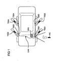
- FIG. 1 a motor vehicle is shown schematically.
- this motor vehicle has a central control unit ZSG, which can be controlled by radio, or optically by means of a remote control RC, for example a motor vehicle key.
- This central control unit ZSG is connected via a bus system CAN with door control units TSG 1, TSG 2, TSG 3 and TSG 4.
- the door control units TSG 1, TSG 2, TSG 3 and TSG 4 are arranged in the four doors of the motor vehicle.
- the connections of the bus communication structure CAN are routed from the motor vehicle interior via a respective door separation point TSS 1, TSS 2, TSS 3 and TSS 4 into the motor vehicle doors and are connected there to the door control devices TSG 1, TSG 2, TSG 3 and TSG 4.
- FIG. 2 A block diagram of the security system is in FIG. 2 shown.
- a door control unit TSG which is connected via an interface TSS with the central control unit ZSG and the battery of the motor vehicle Bat.
- An analogous structure also results for the other door control devices of the motor vehicle.
- the battery Bat has two terminals Ub and GND for the battery voltage potential Ub and the ground terminal GND. Both connections are connected both to the central control unit ZSG and to the door control unit TSG.
- the central control unit ZSG has a microcontroller ⁇ C1 and a CAN bus interface CAN.
- the CAN bus interface CAN is connected via the CAN bus CAN via the door separation point TSS with the CAN bus interface CAN of the door control unit TSG.
- the central control unit has two Potential switch PS 1 and PS 2, wherein the first potential switch PS1 is connected to the battery voltage potential Ub and the control line.
- the second potential switch PS 2 is connected to the control line St and the ground GND.
- the door control unit TSG is in addition to the connection to the central control unit via the CAN bus system CAN and the independent electrical control line St and the supply line to the motor vehicle battery Bat connected to other functional units of the vehicle door.
- Two electromechanical adjusting drives M1 and M2 are connected to the door control unit TSG, which has power switches LS1 and LS2 for energizing the two drives M1 and M2.
- the first adjusting drive M1 is an adjusting drive of a motor vehicle lock, this adjusting drive M1 serving for locking and unlocking the motor vehicle door.
- the second electromechanical drive M2 serves the same lock to switch to the state "locks", a so-called safe state.
- this second power switch LS2 is connected by means of the control line directly to the central control unit.
- the second power switch and the first power switch LS1 are designed as mechanical power switches in the form of relays or the like or as semiconductor full or half bridges.
- the circuit breakers. LS1 and LS2 have several in FIG. 2 not shown control inputs. These control inputs are connected to the microcontroller ⁇ C2 of the door control unit TSG and the control line St or further input circuit.
- the central control unit subsequently switches the control line St by means of the potential switch PS1 to the operating voltage potential of the battery Bat Ub.
- the second potential switch PS2 which has previously connected the control line St to ground, is opened.
- the central control unit sends via the CAN bus CAN a signal in the door control unit TSG, which includes a command for energizing the second electromechanical drive unit M2.
- FIG. 3 illustrated circuit diagram is a section of the more specific embodiment of the illustrated FIG. 2 ,
- the door separation point TSS is shown with the laid by the door separation point TSS connections of the Central control unit ZSG for door control unit TSG.
- the connection here again is the control line St, the battery voltages Ub and the ground connection GND.
- a CAN bus system CAN is provided for communication between the door control unit and the central control unit.
- the door control unit TSG is in turn connected to the lock Sch a motor vehicle door via three Bestromungs effeten.
- the lock Sch the motor vehicle door is arranged in a wet space N of the vehicle door and sealed for this purpose against ingress of moisture.
- the door control unit TSG is arranged on the dry-room side T of the motor vehicle door and has no moisture protection adequate to the wet space.
- the microcontroller ⁇ C1 of the central control unit ZSG and the microcontroller of the door control unit TSG via transceiver circuits Trans 1 and Trans 2 are interconnected, the corresponding hardware for the CAN bus control available put.
- the microcontroller .mu.C1 of the central control unit is connected to a control terminal with a field effect transistor JFET, which enables a connection of the battery voltage Ub to the control line St.
- the microcontroller ⁇ C2 of the door control unit TSG has three outputs which are connected via resistors R1, R2 or R3 to driver transistors, in this case NPN bipolar transistors Q1, Q2 and Q3, respectively.
- the driver transistors Q1, Q2 and Q3 are respectively connected to a relay coil In1, ln2 and In3 of a relay RL1, RL2 and RL3, respectively, and the driver transistors Q1, Q2 and Q3 ground the terminals of the relay coils In1, In2 and In3.
- the other terminal of the relay coils In1 and INn2 is connected to the battery voltage Ub, whereas the relay coil In3 is connected to the second terminal to the control line St.
- This third relay RL3 is used to energize the second electromechanical drive unit M2 of the lock Sch in the direction of the lock state "Safe".
- the control line in order to switch the lock into the blocking state, the control line must be switched to battery voltage potential Ub by means of the field effect transistor JFET of the central control unit and at the same time the driver transistor Q3 must be connected through the microcontroller ⁇ C2 of the door control unit TSG via the third resistor R3. Accordingly, as a condition to operate the lock in the state "lock", by an AND operation on the driver transistor Q3 applied output voltage of the microcontroller ⁇ C2 with the switched field effect transistor JFET of the central control unit ZSG required.
- relay switches S1, S2 and S3 are provided for the actual energization of the drive units M1 and M2 of the lock Sch. These relay switches are connected on the one hand to the ground GND to the other with the battery voltage Ub.
- the relay switch S3 of the third relay RL3 can optionally be connected to the battery voltage Ub or to the control line St via a bridge, a so-called jumper Jp. If the relay switch S3 is additionally connected to the control line St, the second drive unit M2 of the lock Sch is energized via the control line St.
- relays RL1, RL2 and RL3 alternatively power semiconductors can be used, which can also be integrated into the microcontroller ⁇ C2 as smart power elements.
- the semiconductor power switches are designed as discrete elements, their driving is preferably carried out in antiphase, in order to obtain an in-phase noise voltage on the drive terminals of the discrete power switch when a parasitic resistance occurs, which does not cause unwanted switching of the power transistors. This is the case in particular because the parasitic resistors act in the same way on interconnects arranged parallel to one another and serve to drive these discrete power switches.
- FIGS. 4a and 4b is a process flow for securing a motor vehicle lock by means of a flowchart shown schematically.
- the central control unit ZSG receives the "safe" command, ie, the motor vehicle doors, in the "lock” state, for example via a remote control or the actuation of one of the locks by means of a motor vehicle key
- the central control unit can check, for example, at least the door control units TSG of the motor vehicle doors for functionality If a functionality of the CAN bus connection is given, in a third step the query for a CAN size of the motor vehicle, in this Embodiment according to the state of the engine ignition.
- the engine ignition by the ignition key or the like takes place in a fourth step of FIG. 4 a the application of a potential to an independent electrical line connection St.
- a safe control command transmitted to the door control units TSG.
- an error is indicated by the safety system in a sixth step.
- the error is logged in a file and made available for later error diagnosis.
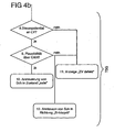
- FIG. 4b shows the second part of the method for securing by the security system, which runs in the door control unit TSG.
- the transmission of the safe control command via the CAN bus to the door control unit is checked in the door control unit TSG by its microcontroller ⁇ C1 the control potential of the control line St. If the control potential corresponds to the potential for blocking the motor vehicle door, a plausibility check of the overall system, in which, for example, the communication system and the functionality of the door control unit is checked, is additionally carried out in a ninth step.
- the lock Sch is activated in the state "Safe". If the control potential for controlling the second electromechanical unit M2 in the direction of blocking is unsuitable in step 8, an indication is given in step 11 about the defective state of the central locking ZV. Similarly, in the eleventh step, the display of a defect of the central locking ZV, if the plausibility check of the ninth step results in a negative result. In this case, in addition to the display in step eleven, the lock is actuated in a twelfth method step in the direction of unlocking in order to be sure that a person in the motor vehicle may leave the motor vehicle when the lock has already reached a locked state ,
- the detection of an error triggers a display of a critical condition in a vehicle display for the vehicle user, and the door locks are driven to the unlocked state.
- An end position in the "safe” is following by the lock mechanism only on the intermediate position “locked” possible, so that in case of failure two conditions must be met necessarily to bring from the state “unlocked” the vehicle door in the state "locked”.
Landscapes
- Engineering & Computer Science (AREA)
- Mechanical Engineering (AREA)
- Lock And Its Accessories (AREA)
- Electric Propulsion And Braking For Vehicles (AREA)
- Control Of Electric Motors In General (AREA)
- High-Pressure Fuel Injection Pump Control (AREA)
Abstract
Description
Die Erfindung betrifft ein Verfahren und ein Sicherungssystem für eine Schließeinrichtung eines Kraftfahrzeugs gemäß dem Oberbegriff des Anspruchs 1.The invention relates to a method and a safety system for a locking device of a motor vehicle according to the preamble of
Aus dem Stand der Technik ist bekannt, im Kraftfahrzeug zur Datenübertragung zwischen elektronisch gesteuerten Einrichtungen serielle Datenprotokolle einer Bus-Technologie zu verwenden. So stehen beispielsweise die einzelnen Karosserie-Steuergeräte, wie die zentrale Karosserieelektronik, Kombiinstrument und Steuergeräte in den Türen in Verbindung. Von der zentralen Karosserieelektronik, einem Zentralsteuergerät des Kraftfahrzeugs, werden Freigabesignale insbesondere für die Funktion Zentralverriegelung generiert und an die ausführenden Steuergeräte mittels eines seriellen Datenprotokolls übertragen. Dabei ist die Funktion der Verriegelung von diesen Freigabesignalen abhängig.From the prior art it is known to use in the motor vehicle for data transmission between electronically controlled devices serial data protocols of a bus technology. For example, the individual body control units, such as the central body electronics, instrument cluster and control units in the doors, are connected. From the central body electronics, a central control unit of the motor vehicle, release signals are generated in particular for the function of central locking and transmitted to the executing control devices by means of a serial data protocol. The function of the lock depends on these enable signals.
Darüber hinaus ist bekannt, bei einem kompletten Ausfall des Bus-Systems die Türsteuergeräte automatisch in einen Notlauf-Betrieb umzuschalten, um sicherheitsrelevante, freigabeabhängige Funktionen weiterhin zu ermöglichen. Es hat sich jedoch herausgestellt, daß schon beim Ausfall eines Teils der über den Bus verbundenen Elektroniken (Zentralsteuergerät oder daran angeschlossene weitere Geräte des Kraftfahrzeugs) wichtige oder sogar sämtliche Funktionen der Verstellsysteme blockiert sein können, weil eine ausgefallene Elektronik nicht mehr die Daten liefern konnte, die zur Generierung der Freigabesignale notwendig waren. Derartige Notlaufbetriebe für Fensterheber sind beispielsweise aus der
Zudem ist die technische Funktionalität der Verstellsysteme von der Funktionsfähigkeit und Zuverlässigkeit der Steuergeräte abhängig. Unfallsituationen, die zu einer Teilzerstörung der Steuerungselektroniken führen, bergen die Gefahr parasitäre Widerstände zu generieren, die eine Isolation zwischen zwei Leiterbahnen der Elektronik des Türsteuergerätes deutlich herabsetzen. Derart verursachte parasitäre Widerstände können Werte von wenigen hundert Ohm aufweisen. Entsteht dieser Widerstand zwischen einem Ansteuerungsanschluß eines Leistungsschalters und einem festen Potential, insbesondere der Batteriespannung oder des Masseanschlusses, kann dies zu einem unerwünschten Ansteuern des Leistungsschalters und in Folge zu einer unerwünschten Verstellung der Verstelleinrichtung führen.In addition, the technical functionality of the adjustment systems depends on the functionality and reliability of the control units. Accident situations that lead to a partial destruction of the control electronics, the risk of generating parasitic resistors that significantly reduce isolation between two tracks of the electronics of the door control unit. Thus caused parasitic resistances can have values of a few hundred ohms. If this resistance arises between a drive connection of a circuit breaker and a fixed potential, in particular the battery voltage or the ground connection, this can lead to an undesired activation of the circuit breaker and consequently to an undesired adjustment of the adjustment device.
Der Ausfall von Teilen der Fahrzeugelektrik, insbesondere des Bus-Systems oder des Steuergerätes durch Crasheinwirkungen kann durch die unerwünschte Verstellung der Verstelleinrichtung in der unfallbedingten Notsituation zu zusätzlichen Gefährdungen führen.The failure of parts of the vehicle electrical system, in particular the bus system or the control unit by crash effects can lead to additional hazards by the unwanted adjustment of the adjustment in the accidental emergency situation.
Die
Die
Der Erfindung liegt die Aufgabe zu Grunde, ein Verfahren und ein System zur Sicherung einer Schließeinrichtung eines Kraftfahrzeugs anzugeben, das die Öffnung der Schließeinrichtung bei einem Ausfall von Teilen des Systems ermöglicht und zugleich die Gefahr von automatischen Ansteuerungen in einen nicht erwünschten Zustand oder manuellen Fehlfunktionen verringert.The invention has for its object to provide a method and a system for securing a locking device of a motor vehicle, which allows the opening of the locking device in case of failure of parts of the system and at the same time reduces the risk of automatic actuation in an undesirable state or manual malfunction ,
Diese Aufgabe wird durch das Sicherungssystem mit den Merkmalen des Patentanspruchs 1 und durch das Verfahren mit den Merkmalen des Patentanspruchs 14 gelöst. Vorteilhafte Weiterbildungen der Erfindung sind den Unteransprüchen zu entnehmen.This object is achieved by the security system having the features of
Demgemäß ist ein Sicherungssystem für eine Schließeinrichtung eines Kraftfahrzeugs vorgesehen, wobei ein Steuergerät, das Bestandteil des Sicherungssystems ist, mindestens einen Leistungsschalter zum Steuern einer elektromechanischen Einheit in den Zustand "Sperren", auch "safe" genannt, aufweist und welcher durch ein Zentralsteuergerät zusätzlich beeinflußbar ist. Dieser Sperrzustand unterscheidet sich von Verriegelungszuständen "Entriegelt" und "Verriegelt" der Schließeinrichtung der Kraftfahrzeugtür.Accordingly, a security system for a locking device of a motor vehicle is provided, wherein a control unit, which is part of the security system, at least one circuit breaker for controlling an electromechanical unit in the state "locks", also called "safe", and which additionally influenced by a central control unit is. This locked state differs from the locked states "unlocked" and "locked" of the closing device of the vehicle door.
Ist die elektromechanische Einheit im Zustand "Entriegelt", läßt sich die Kraftfahrzeugtür manuell sowohl von außen als auch von der Kraftfahrzeuginnenseite her öffnen oder die Kraftfahrzeugtür ist automatisch mittels eines motorischen Antriebs zu öffnen.If the electromechanical unit is in the "unlocked" state, the motor vehicle door can be opened manually both from the outside and from the motor vehicle inside or the motor vehicle door can be opened automatically by means of a motor drive.
Im Zustand "Verriegelt" ist die Kraftfahrzeugtür von außen her nicht mehr zu öffnen, jedoch sind weiterhin alle mechanischen Funktionen der elektromechanischen Einheit aktiviert, so daß die Kraftfahrzeugtür von innen zu öffnen ist, was auch hilfweise durch ein entsprechendes Werkzeug von außen möglich ist, sollte sich der Fahrzeugbenutzer unbeabsichtigt ausgesperrt haben.In the "locked" state, the motor vehicle door from the outside is no longer open, but all mechanical functions of the electromechanical unit continue to be activated, so that the vehicle door should be opened from the inside, which is also possible by a corresponding tool from the outside, should the vehicle user has locked out unintentionally.
Um einen Diebstahl des Kraftfahrzeugs zu verhindern, werden die elektromechanischen Einheiten des Kraftfahrzeugs in den Zustand "Sperren" versetzt. Im Zustand "Sperren" sind alle mechanischen Funktionen der elektromechanischen Einheit deaktiviert, so daß die Kraftfahrzeugtür mit dem hilfswerkzeug oder vom Kraftfahrzeuginneren aus nicht mehr manuell durch die Betätigung von mechanischen Komponenten der elektromechanischen Einheit zu öffnen ist.In order to prevent a theft of the motor vehicle, the electromechanical units of the motor vehicle are placed in the state "locks". In the state "locks" all mechanical functions of the electromechanical unit are disabled, so that the vehicle door with the utility tool or from the vehicle interior is no longer open manually by the operation of mechanical components of the electromechanical unit.
Diese unterschiedlichen Zustände werden durch die elektromechanische Einheit bewirkt, die durch die Zuführung von elektrischer Energie mittels mechanischer Verstellungen zumindest die Zustände "Entriegelt", "Verriegelt" und "Sperren" herbeiführt. Die beschriebenen Zustände können prinzipiell für die jeweiligen Kraftfahrzeugtüren oder auch die Heckklappe des Kraftfahrzeugs unterschiedlich sein.These different states are caused by the electromechanical unit, which causes at least the states "unlocked", "locked" and "locking" by the supply of electrical energy by means of mechanical adjustments. The states described may in principle be different for the respective motor vehicle doors or also for the tailgate of the motor vehicle.
Bevorzugt werden die Zustände aller Schließeinheiten eines Automobiles durch das Zentralsteuergerät mittels serieller Datenprotokolle aufeinander abgestimmt.The states of all closing units of an automobile are preferably matched to one another by the central control unit by means of serial data protocols.
Hierzu ist ein Zentralsteuergerät vorgesehen, das Signalverbindungen, insbesondere eine serielle Busverbindung, zu den Steuergeräten der jeweiligen Tür des Kraftfahrzeugs aufweist. Diese Signalverbindungen ermöglichen eine Datenübertragung zur Herbeiführung der gewünschten Zustände, indem die elektromechanische Einheit durch das Zentralsteuergerät über die Signalverbindungen ansteuerbar ist. Beispielsweise ermöglichen die Signalverbindungen eine Datenübertragung zur Übermittlung von gewünschten Zuständen vom Zentralsteuergerät an die jeweiligen Steuergeräte zur Ansteuerung der lokalen Schließeinrichtung.For this purpose, a central control unit is provided which has signal connections, in particular a serial bus connection, to the control devices of the respective door of the motor vehicle. These signal connections enable data transmission to bring about the desired states in that the electromechanical unit can be actuated by the central control device via the signal connections. For example, the signal connections enable data transmission for the transmission of desired states from the central control device to the respective control devices for controlling the local closing device.
Die Datenübertragung ist in einem einfachen Fall ein zu dem jeweiligen Zustand zugeordnetes Signal, eine Spannung oder Binärdaten. Komplexere Verbindungen ermöglichen eine Verbesserung der Zuverlässigkeit der Übertragung und die Übertragung von Befehlen, Statusdaten und/oder Diagnosedaten der elektromechanischen Einheit oder von Bedienelementen.In a simple case, the data transmission is a signal assigned to the respective state, a voltage or binary data. More complex links enable the reliability of the transmission and the transmission of commands, status data and / or diagnostic data of the electromechanical unit or controls to be improved.
Zur Sicherung dieses Systems ist das Türsteuergerät mit dem Zentralsteuergerät über eine von den Signalverbindungen unabhängige elektrische Leitungsverbindung verbunden. Für eine Unabhängigkeit dieser elektrischen Leiturigsverbindung ist es notwendig, daß die über die Signalverbindungen übertragenen Spannungen oder Signale diese unabhängige elektrische Leitungsverbindung nicht stören. Eine besonders zweckmäßige und einfache Ausführung der Erfindung sieht vor, daß als unabhängige elektrische Leitungsverbindung ein von den Signalverbindungen elektrisch isolierter, separater Leiter verwendet wird.To secure this system, the door control unit is connected to the central control unit via an independent of the signal connections electrical line connection. For independence of this electrical Leiturigsverbindung it is necessary that the signals or signals transmitted via the signal connections do not interfere with this independent electrical line connection. A particularly expedient and simple embodiment of the invention provides that an independent conductor electrically isolated from the signal connections, is used as an independent electrical line connection.
Über diese unabhängige elektrische Leitungsverbindung ist ein Potential eines Ansteuerungsanschlusses des zuvor genannten Leistungsschalters zur Bestromung der elektromechanischen Einheit oder ein Leistungsanschluß des Steuergerätes, der mit der elektromechanischen Einheit verbindbar ist, von dem Zentralsteuergerät steuerbar. Die Steuerung erfolgt vorzugsweise direkt, indem der Ansteuerungsanschluß oder der Leistungsanschluß mit dem Zentralsteuergerät über die unabhängige elektrische Leitungsverbindung direkt elektrisch verbunden ist. Alternativ könnte das Potential des betreffenden Anschlusses vom Zentralsteuergerät auch indirekt steuerbar sein, indem zwischen der unabhängigen elektrischen Leitung und dem betreffenden Anschluß ein weiteres logisches Element, beispielsweise ein Schalttransistor zwischengeschaltet ist.About this independent electrical line connection is a potential of a drive terminal of the aforementioned circuit breaker for energizing the electromechanical unit or a power terminal of the control unit, which is connectable to the electromechanical unit, controllable by the central control unit. The control is preferably carried out directly by the drive terminal or the power terminal is electrically connected directly to the central control unit via the independent electrical line connection. Alternatively, the potential of the relevant terminal could also be indirectly controlled by the central control unit by interposing a further logic element, for example a switching transistor, between the independent electrical line and the relevant terminal.
Demzufolge erfolgt über die unabhängige elektrische Leitungsverbindung von der Zentralelektronik zu den jeweiligen lokalen Steuergeräten die Ansteuerung mit einer zusätzlichen Freigabeabhängigkeit, wobei ohne diese Freigabe ein Ansteuern der elektromechanischen Einheit in den Zustand "Sperren" nicht möglich ist.Accordingly, via the independent electrical line connection from the central electronics to the respective local control units, the control with an additional release dependency, without this release, a driving of the electromechanical unit in the state "locks" is not possible.
Gemäß einer vorteilhaften Weiterbildung der Erfindung gibt das Zentralsteuergerät die Ansteuerung der elektromagnetischen Einheit in Richtung "Sperren" nur dann frei, wenn die Funktionsfähigkeit der seriellen Datenübertragung über die Signalverbindung gewährleistet ist, was beispielsweise durch eine fortlaufende Statusabfrage aller beteiligten Steuergeräte und des Zentral steuergeräte erfolgen kann. Hierzu weist das Zentralsteuergerät vorteilhafterweise eine Auswertevorrichtung auf, die zur Steuerung des Leistungsanschlusses in Abhängigkeit von einem Zustand oder einem Notbetrieb der Signalverbindungen ausgebildet ist. Diese Auswertevorrichtung fragt beispielsweise zyklisch die Knoten eines Bussystems der Signalverbindungen ab, um deren Funktionsfähigkeit und die Funktionsfähigkeit der Signalverbindungen zu prüfen. Vorteilhafterweise werden zusätzlich Fahrzeugzustände, insbesondere der Zündungszustand ausgewertet. Eine ausgeschaltete Zündung ist dabei eine weitere Bedingung zur Steuerung des Potentials des Ansteuerungsanschlusses. Ist zumindest eine Bedingung nicht erfüllt, beispielsweise der Ausfall des seriellen Datenprotokolls aufgrund physikalischer Einwirkungen im Crashfall, ist die Freigabebedingung nicht erfüllt, d.h. diese wird zurückgesetzt, so daß das Potential auf die unabhängige elektrische Leitungsverbindung durch das Zentralsteuergerät nicht gesteuert wird.According to an advantageous embodiment of the invention, the central control unit releases the control of the electromagnetic unit in the direction of "locks" only if the functionality of the serial data transmission is ensured via the signal connection, which can be done for example by a continuous status query of all controllers involved and the central control unit , For this purpose, the central control device advantageously has an evaluation device which is used to control the power connection is formed as a function of a state or an emergency operation of the signal connections. For example, this evaluation device cyclically queries the nodes of a bus system of the signal connections in order to check their functionality and the functionality of the signal connections. Advantageously, additional vehicle states, in particular the ignition state are evaluated. A switched off ignition is a further condition for controlling the potential of the control connection. If at least one condition is not met, for example, the failure of the serial data protocol due to physical effects in the event of a crash, the release condition is not met, ie this is reset, so that the potential is not controlled on the independent electrical line connection by the central control unit.
Eine vorteilhafte Ausgestaltung der Erfindung sieht vor, daß zur Steuerung das Potential auf diese unabhängige elektrische Leitungsverbindung schaltbar ist. Vorzugsweise weist der Ausgang des Zentralsteuergerätes für diesen Schaltvorgang einen niederohmigen Ausgang auf, der die Neigung dieser unabhängigen elektrischen Leitungsverbindung auf Störeinflüsse empfindlich zu reagieren, deutlich reduziert. Ein derartiger niederohmiger Ausgang wird beispielsweise durch die Verwendung von Schalttransistoren realisiert, die neben dem Anschluß zur unabhängigen elektrischen Leitungsverbindung einen weiteren Anschluß zu einer Strom- oder Spannungsquelle, beispielsweise zu der Batteriespannung Ub oder zur Masse aufweisen.An advantageous embodiment of the invention provides that the potential for controlling this independent electrical line connection can be switched to control. Preferably, the output of the central control unit for this switching operation on a low-impedance output, the sensitivity of this independent electrical line connection to susceptible to interference sensitive, significantly reduced. Such a low-impedance output is realized, for example, by the use of switching transistors which, in addition to the connection to the independent electrical line connection, have a further connection to a current or voltage source, for example to the battery voltage Ub or to ground.
Aufgrund des geringen Ausgangswiderstandes haben parasitäre Widerstände, die in einer Unfallsituation auftreten können, nur einen geringen Einfluss auf dieses an der unabhängigen elektrischen Leitungsverbindung anliegende Potential. Zudem bietet in einer anderen Ausgestaltung der Erfindung das Schalten der Batteriespannung bzw. des Masseanschlusses die Möglichkeit, über diese unabhängige elektrische Leitungsverbindung die Antriebsenergie für die elektromechanische Einheit zumindest für eine Verstellrichtung zu übertragen.Due to the low output resistance parasitic resistances that can occur in an accident situation, have only a small influence on this voltage applied to the independent electrical line connection potential. In addition, in another embodiment of the invention, the switching of the battery voltage or of the ground connection offers the possibility of transmitting the drive energy for the electromechanical unit at least for one adjustment direction via this independent electrical line connection.
In einer weiteren Ausgestaltung der Erfindung weist das Zentralsteuergerät mindestens einen Schalter zum Schalten von mindestens zwei unterschiedlichen Potentialen auf. Diese Potentiale sind beispielsweise das genannte Massepotential oder das Batteriespannungspotential. Wird dagegen eine digitale Auswertung des Potentials bevorzugt, kann auch ein Logikpegel, beispielsweise ein Pegel von 5 Volt, als eines des zwei unterschiedlichen Potentiale dienen. Mittels dieses Umschaltens der beiden Potentiale wird vermieden, daß in einem Zeitzustand ein hochohmiger Ausgang des Zentralsteuergerätes zu einem undefinierten Potential auf der unabhängigen elektrischen Leitungsverbindung führt.In a further embodiment of the invention, the central control unit has at least one switch for switching at least two different potentials. These potentials are, for example, the named ground potential or the battery voltage potential. If, on the other hand, a digital evaluation of the potential is preferred, a logic level, for example a level of 5 volts, can also serve as one of the two different potentials. By means of this switching of the two potentials is avoided that in a time state, a high-impedance output of the Central control unit leads to an undefined potential on the independent electrical line connection.
Um eine weitere Erhöhung der Sicherheit dieses Sicherungsystems zu erreichen, sind in einer besonders vorteilhaften Weiterbildung der Erfindung zum Steuern des Zustands "Sperren" die Steuerung des Potentials durch das Zentralsteuergerät und einer Ansteuerung durch die Logik des Steuergerätes logisch UND verknüpft. Die Logik des Türsteuergerätes ist dabei beispielsweise ein im Türsteuergerät integrierter Mikrocontroller, der wiederum über eine der Signalverbindungen mit dem Zentralsteuergerät verbunden sein kann. Durch diese logische UND-Verknüpfung wird eine Sicherungsredundanz erzeugt, die den Einfluß parasitärer Widerstände weiter reduziert. Weiterhin kann mit der Prüfung der Eingangszustände der logischen UND-Verknüpfung geprüft werden, ob das Steuergerät der Tür und das Zentralsteuergerät sich in einem Normalbetrieb befinden.In order to achieve a further increase in the security of this security system, the control of the potential by the central control unit and a control by the logic of the control unit are logically AND linked in a particularly advantageous embodiment of the invention for controlling the state "locks". The logic of the door control unit is for example a built-in door control unit microcontroller, which in turn can be connected via one of the signal connections to the central control unit. This logical AND operation produces a backup redundancy which further reduces the influence of parasitic resistances. Furthermore, it can be checked by checking the input states of the logical AND operation, whether the control unit of the door and the central control unit are in normal operation.
Eine vorteilhafte Ausgestaltung dieser Weiterbildung der Erfindung sieht vor, daß zur logischen UND-Verknüpfung der Schalter des Zentralsteuergerätes und ein Schalter der Logik des Türsteuergerätes eine Reihenschaltung bilden. Die Schalter sind bevorzugt mechanische Schalter, insbesondere Schalttransistoren, die wiederum über einen Steuerungsanschluss verfügen. Eine erste Untervariante dieser Ausgestaltung der Erfindung sieht vor, daß beide Schalter direkt elektrisch miteinander verbunden sind. Alternativ sieht die zweite Untervariante dieser Ausgestaltung vor, daß beide Schalter über ein weiteres Element insbesondere über mindestens einen Anschluss des Leistungsschalter bzw. des Leistungsanschlusses des Türsteuergerätes miteinander verbunden sind. Vorzugsweise ist das Potential zur Ansteuerung des Leistungsschalters zwischen dem Massepotential und einem Ansteuerpotential, was das kleiner oder gleich des Batteriepotentials sein kann, schaltbar.An advantageous embodiment of this embodiment of the invention provides that form a series circuit for logical AND operation of the switch of the central control unit and a switch of the logic of the door control unit. The switches are preferably mechanical switches, in particular switching transistors, which in turn have a control connection. A first sub-variant of this embodiment of the invention provides that both switches are directly electrically connected to each other. Alternatively, the second sub-variant of this embodiment provides that both switches are connected to each other via a further element in particular via at least one terminal of the circuit breaker and the power terminal of the door control unit. Preferably, the potential for driving the power switch between the ground potential and a drive potential, which may be less than or equal to the battery potential, switchable.
Um eine weitere Erhöhung der Sicherheit dieses Sicherungssystems zu erreichen, erfolgt in einer vorteilhaften Ausgestaltung der Erfindung in jedem lokalen Steuergerät zur Ansteuerung der elektromechanischen Einheit eine vorzugsweise permanente Plausibilitätsprüfung, in der das Freigabepotential der unabhängigen elektrischen Leitungsverbindung nur dann aufgeschaltet wird, wenn die Bedingungen "Zündung aus" und "ungestörte Signalverbindungen" erfüllt sind.In order to achieve a further increase in the security of this security system, in an advantageous embodiment of the invention in each local control unit for controlling the electromechanical unit, a preferably permanent plausibility check, in which the release potential of the independent electrical line connection is switched only when the conditions "ignition from "and" undisturbed signal connections "are met.
Eine bevorzugte Weiterbildung der Erfindung sieht vor, daß die Verbindungen Bestandteil eines Bussystems sind. Dieses Bussystem ist vorzugsweise ein CAN-Bussystem, daß eine Verbindung mit dem Zentralsteuergerät und weiteren Geräten des Kraftfahrzeuges ermöglicht. Wird zumindest eine bidirektionale Verbindung, beispielsweise die eines CAN-Busses genutzt, ist eine Übertragung von Statusdaten zwischen den Geräten des Kraftfahrzeuges möglich. Neben den Statusdaten können weitere Informationen über einen Betriebsmodus, beispielsweise einem Notbetrieb während einer Unfallsituation oder einem Defekt der Geräte und einem Normalbetrieb übertragen werden. Weitere Ausgestaltung dieser Weiterbildung läßt zusätzlich eine Übertragung von Diagnosedaten über das CAN-Bussystem zu, die die aktuelle Zuverlässigkeit einzelner Elemente des Sicherungssystems, insbesondere die Zuverlässigkeit der Potentiale bzw. der unabhängigen elektrischen Leitungsverbindung an das Zentralsteuergerät protokollieren.A preferred embodiment of the invention provides that the compounds are part of a bus system. This bus system is preferably a CAN bus system, that allows a connection with the central control unit and other devices of the motor vehicle. If at least one bidirectional connection, for example that of a CAN bus used, a transmission of status data between the devices of the motor vehicle is possible. In addition to the status data, further information about an operating mode, for example an emergency operation during an accident situation or a defect of the devices and a normal operation can be transmitted. Another embodiment of this development also allows a transmission of diagnostic data via the CAN bus system, which log the current reliability of individual elements of the security system, in particular the reliability of the potentials or the independent electrical line connection to the central control unit.
Eine besonders vorteilhafte Ausgestaltung der Erfindung sieht vor, daß das Steuergerät einen Mikrocontroller aufweist. Bestandteil dieses Mikrocontrollers ist beispielsweise eine Logik, die die logische UND-Verknüpfung mit der Steuerung des Zentralsteuergerätes ermöglicht. Weiterhin dient dieser Mikrocontroller zur Steuerung und Berechnung weiterer Operationen der Funktionselemente der Kraftfahrzeugtür. Dieser Mikrocontroller ist zudem zur Ansteuerung mit dem Leistungsschalter über dessen Ansteuerungsanschluss verbunden. Hierzu kann ein Ausgangs-PIN des Mikrocontrollers direkt mit einem diskreten Leistungsschalter in Form eines Leistungstransistors oder eines Relais' verbunden sein. Alternativ ist ebenso eine indirekte Beschaltung über eine weitere Logik des Steuergerätes der Tür oder über eine Logik des Zentralsteuergerätes möglich. Für eine Ansteuerung des Relais' kann die Verbindung über einen Treibertransistor zur Bestromung der Relaisspule vorteilhaft sein. Alternativ zur Verbindung über Leitungselemente einer Platine kann der Mikrocontroller zusammen mit dem Leistungsschalter auf einem Halbleiterchip als sogenannte Smart-Power-Technologie integriert sein.A particularly advantageous embodiment of the invention provides that the control unit has a microcontroller. Part of this microcontroller, for example, a logic that allows the logical AND logic with the control of the central control unit. Furthermore, this microcontroller is used to control and calculate further operations of the functional elements of the motor vehicle door. This microcontroller is also connected to the circuit breaker via its drive connection for driving. For this purpose, an output PIN of the microcontroller can be connected directly to a discrete power switch in the form of a power transistor or a relay. Alternatively, an indirect wiring via a further logic of the control unit of the door or via a logic of the central control unit is also possible. For a control of the relay ', the connection via a driver transistor for energizing the relay coil may be advantageous. As an alternative to connection via line elements of a circuit board, the microcontroller can be integrated together with the power switch on a semiconductor chip as so-called smart power technology.
In einer vorteilhaften Weiterbildung der Erfindung ist vorgesehen, daß der Mikrocontroller des Steuergerätes mit der unabhängigen elektrischen Leitungsverbindung zur Auswertung wirkverbunden ist. Diese Wirkverbindung ermöglicht die Detektion von Zuständen und Fehlfunktionen der Leitungsverbindung bzw. der übertragenden Signale oder Potentiale. Diese Fehlfunktionen können von dem Steuergerät ausgewertet werden, oder alternativ in einer vorteilhaften Ausgestaltung dieser Weiterbildung der Erfindung ist vorgesehen, daß der Mikrocontroller des Steuergerätes über eine der Signalverbindungen einen Status des Potentials des Ansteuerungsanschlusses des Leitungsschalters oder des Zustands der elektromechanischen Einheit an das Zentralsteuergerät überträgt. In diesem Fall ist eine Auswertung der detektierten Zustände und Funktionalitäten durch das Zentralsteuergerät möglich, indem dieses alle von dem Steuergerät detektierten zeitlichen Veränderungen auswertet und mittels einer Plausibilitätsprüfung Abweichung von einem Normalbetrieb registriert und ggf. einen Notbetrieb startet. In diesem Notbetrieb wird nun beispielsweise folgend eine Freigabe zur Ansteuerung der elektromechanischen Einheit in Richtung "Sperren" verändert.In an advantageous development of the invention, it is provided that the microcontroller of the control unit is operatively connected to the independent electrical line connection for evaluation. This active connection enables the detection of states and malfunctions of the line connection or of the transmitted signals or potentials. These malfunctions can be evaluated by the controller, or alternatively in an advantageous embodiment of this embodiment of the invention it is provided that the microcontroller of the controller via one of the signal connections a status of the potential of the drive terminal of the line switch or the state of the electromechanical unit to the Central control unit transmits. In this case, an evaluation of the detected states and functionalities by the central control unit is possible by this evaluates all detected by the control unit temporal changes and registered by a plausibility check deviation from a normal operation and possibly starts an emergency operation. In this emergency operation, for example, following a release to control the electromechanical unit is changed in the direction "locks".
In einer weiteren vorteilhaften Weiterbildung der Erfindung ist zusätzlich ein Fensterheberantrieb der Kraftfahrzeugtür in Richtung "Schließen" über die unabhängige elektrische Leitungsverbindung freigebbar. Mittels dieser Kontrolle der Fensterheberzustände soll verhindert werden, daß ein automatisches Schließen in einem Notbetriebsfall verhindert wird. Ist der Schwerzustand der elektromechanischen Einheit bereits erreicht und ein Entsperren nicht mehr möglich, so wird in einem Notbetriebsfall der Fensterheberantrieb derart angesteuert, daß ein automatisches Öffnen der Fensterscheibe für diesen Notbetrieb möglich ist.In a further advantageous development of the invention, a window lifter drive of the motor vehicle door can additionally be released in the direction "closing" via the independent electrical line connection. By means of this control of the power window states is to be prevented that an automatic closing is prevented in an emergency operation. If the heavy state of the electromechanical unit has already been reached and unlocking is no longer possible, the window lifter drive is controlled in such an emergency operation that an automatic opening of the window pane for this emergency operation is possible.
Ein Verfahren zur Sicherung dieser Verstelleinrichtung eines Kraftfahrzeugs ist besonders vorteilhaft einsetzbar. Hierzu kann beispielweise das zuvor dargelegte Sicherungssystem oder ein abgewandeltes Sicherungssystem verwendet werden. Vorteilhafterweise wird zur Steuerung eines Schlosses des Kraftfahrzeugs in den Zustand "Sperren" (safe) in einem ersten Verfahrenschritt die Funktionstüchtigkeit eines Zentralsteuergerätes und dessen Verbindungen ausgewertet. Um den Betriebszustand des Kraftfahrzeugs zu bestimmen, wird eine charakterisierende Kenngröße ausgewertet. Diese Kenngröße ist beispielsweise der Schaltzustand der Zündung des Kraftfahrzeugs, so daß ein "Sperren" des Kraftfahrzeuges nicht erfolgen soll, wenn die Zündung eingeschaltet ist.A method for securing this adjusting device of a motor vehicle can be used particularly advantageously. For this purpose, for example, the security system set out above or a modified security system can be used. Advantageously, to control a lock of the motor vehicle in the state "lock" (safe) in a first process step, the functionality of a central control unit and its compounds is evaluated. In order to determine the operating state of the motor vehicle, a characterizing parameter is evaluated. This parameter is, for example, the switching state of the ignition of the motor vehicle, so that a "lock" of the motor vehicle should not take place when the ignition is turned on.
Stellt der Betriebszustand des Kraftfahrzeugs für ein "Sperren" durch das Schloß keine Gefahr für den Insassen des Kraftfahrzeuges dar, wird ein Potential zur Steuerung des Schlosses auf eine von den Signalverbindungen unabhängige elektrische Leitungsverbindung aufgeschaltet. Ein Steuerbefehl wird über eine der Signalverbindungen des Zentralsteuergerätes an ein Steuergerät übertragen. Wenn durch die Auswertung eine fehlerfreie Funktionsweise der Geräte und der Signalverbindung detektiert ist, wird durch einen Leistungsschalter des Steuergerätes der Tür mittels des Potentials eine elektromechanische Einheit des Schlosses bestromt und das Schloß in den Zustand "Sperren" geschaltet.If the operating state of the motor vehicle for a "lock" through the lock is no danger to the occupant of the motor vehicle, a potential for controlling the lock is switched to an independent of the signal connections electrical line connection. A control command is transmitted via one of the signal connections of the central control unit to a control unit. If an error-free operation of the devices and the signal connection is detected by the evaluation, is energized by a circuit breaker of the control unit of the door by means of the potential of an electromechanical unit of the castle and the lock in the state "locks".
Im folgenden wird die Erfindung anhand von Ausführungsbeispielen bezugnehmend auf schematische zeichnerische Darstellungen näher erläutert.In the following the invention will be explained in more detail with reference to exemplary embodiments with reference to schematic drawings.
Dabei zeigen
- FIG 1
- ein Kraftfahrzeug mit einer Kommunikationsstruktur,
- FIG 2
- ein Blockschaltbild eines Sicherungssystems,
- FIG 3
- ein Schaltplanauszug eines Sicherungssystems,
- FIG 4a und FIG 4b
- ein Ablaufdiagramm eines Sicherungsverfahrens.
- FIG. 1
- a motor vehicle with a communication structure,
- FIG. 2
- a block diagram of a security system,
- FIG. 3
- a schematic diagram of a security system,
- 4a and 4b
- a flow chart of a backup process.
In
Ein Blockschaltbild des Sicherungssystems ist in
Das Türsteuergerät TSG ist neben der Verbindung mit dem Zentralsteuergerät über das CAN-Bussystem CAN und der unabhängigen elektrischen Steuerleitung St sowie der Versorgungsleitung zur Kraftfahrzeugbatterie Bat mit weiteren Funktionseinheiten der Kraftfahrzeugtür verbunden. Zwei elektromechanische Verstellantriebe M1 und M2 sind mit dem Türsteuergerät TSG verbunden, das zur Bestromung der beiden Antriebe M1 und M2 Leistungsschalter LS1 und LS2 aufweist. Der erste Verstellantrieb M1 ist ein Verstellantrieb eines Kraftfahrzeugschlosses, wobei dieser Verstellantrieb M1 zum Verriegeln und Entriegeln der Kraftfahrzeugtür dient. Der zweite elektromechanische Antrieb M2 dient demselben Schloß um in den Zustand "Sperren", ein sogenannter Safe-Zustand, zu schalten.The door control unit TSG is in addition to the connection to the central control unit via the CAN bus system CAN and the independent electrical control line St and the supply line to the motor vehicle battery Bat connected to other functional units of the vehicle door. Two electromechanical adjusting drives M1 and M2 are connected to the door control unit TSG, which has power switches LS1 and LS2 for energizing the two drives M1 and M2. The first adjusting drive M1 is an adjusting drive of a motor vehicle lock, this adjusting drive M1 serving for locking and unlocking the motor vehicle door. The second electromechanical drive M2 serves the same lock to switch to the state "locks", a so-called safe state.
Um diesen zweiten Verstellantrieb mittels des zweiten Leistungsschalter LS2 zu bestromen, ist dieser zweite Leistungsschalter LS2 mittels der Steuerleitung direkt mit dem Zentralsteuergerät verbunden. Der zweite Leistungsschalter und der erste Leistungsschalter LS1 sind als mechanische Leistungsschalter in Form von Relais oder dergleichen oder als Halbleiter-Voll- oder -Halbbrücken ausgebildet. Die Leistungsschalter . LS1 und LS2 weisen hierzu mehrere in
Um das Schloß in den Zustand "Sperren" zu verstellen, wird zunächst geprüft, ob das Sicherungssystem sich in einem Normalbetrieb befindet. Das Zentralsteuergerät schaltet nachfolgend die Steuerleitung St mittels des Potentialschalters PS1 auf das Betriebsspannungspotential der Batterie Bat Ub. Hierzu wird der zweite Potentialschalter PS2, der die Steuerleitung St zuvor mit der Masse verbunden hat, geöffnet. Als nachfolgenden Schritt sendet das Zentralsteuergerät über den CAN-Bus CAN ein Signal in das Türsteuergerät TSG, das ein Befehl zur Bestromung der zweiten elektromechanischen Antriebseinheit M2 beinhaltet.To set the lock in the state "locks", it is first checked whether the security system is in a normal operation. The central control unit subsequently switches the control line St by means of the potential switch PS1 to the operating voltage potential of the battery Bat Ub. For this purpose, the second potential switch PS2, which has previously connected the control line St to ground, is opened. As a subsequent step, the central control unit sends via the CAN bus CAN a signal in the door control unit TSG, which includes a command for energizing the second electromechanical drive unit M2.
Der in
Hingegen ist das Türsteuergerät TSG auf der Trockenraumseite T der Kraftfahrzeugtür angeordnet und weist keinen zum Naßraum adäquaten Feuchtigkeitsschutz auf. Zur Kommunikation zwischen dem Türsteuergerät und dem Zentralsteuergerät über den CAN-Bus CAN sind die Mikrocontroller µC1 des Zentralsteuergerätes ZSG und der Mikrocontrolller des Türsteuergerätes TSG über Transceiver-Schaltkreise Trans 1 und Trans 2 miteinander verbunden, die eine entsprechende Hardware für die CAN-BusKontrolle zur Verfügung stellen. Zusätzlich ist der Mikrocontroller µC1 des Zentralsteuergerätes mit einem Steueranschluß mit einem Feldeffekttransistor JFET verbunden, der ein Aufschalten der Batteriespannung Ub auf die Steuerleitung St ermöglicht.By contrast, the door control unit TSG is arranged on the dry-room side T of the motor vehicle door and has no moisture protection adequate to the wet space. For communication between the door control unit and the central control unit via the CAN bus CAN, the microcontroller μC1 of the central control unit ZSG and the microcontroller of the door control unit TSG via
Der Mikrocontroller µC2 des Türsteuergerätes TSG weist drei Ausgänge auf, die über Widerstände R1, R2 oder R3 mit Treibertransistorern, in diesem Fall NPN Bipolartransistoren Q1, Q2 bzw. Q 3 verbunden sind. Die Treibertransistoren Q1, Q2 und Q3 sind jeweils mit einer Relaisspule In1, ln2 bzw. In3 eines Relais RL1, RL2 bzw. RL3 verbunden, dabei schalten die Treibertransistoren Q1, Q2 und Q3 die Anschlüsse der Relaisspulen In1, In2 und In3 gegen Masse. Der jeweils andere Anschluß der Relaisspulen In1 und INn2 ist mit der Batteriespannung Ub verbunden, wohingegen die Relaisspule In3 mit dem zweiten Anschluss mit der Steuerleitung St verbunden ist. Dieses dritte Relais RL3 dient zur Bestromung der zweiten elektromechanischen Antriebseinheit M2 des Schlosses Sch in Richtung des Sperrzustandes "Safe".The microcontroller μC2 of the door control unit TSG has three outputs which are connected via resistors R1, R2 or R3 to driver transistors, in this case NPN bipolar transistors Q1, Q2 and Q3, respectively. The driver transistors Q1, Q2 and Q3 are respectively connected to a relay coil In1, ln2 and In3 of a relay RL1, RL2 and RL3, respectively, and the driver transistors Q1, Q2 and Q3 ground the terminals of the relay coils In1, In2 and In3. The other terminal of the relay coils In1 and INn2 is connected to the battery voltage Ub, whereas the relay coil In3 is connected to the second terminal to the control line St. This third relay RL3 is used to energize the second electromechanical drive unit M2 of the lock Sch in the direction of the lock state "Safe".
Um das Schloß in den Sperrzustand zu schalten, muß demzufolge die Steuerleitung mittels des Feldeffekttransistors JFET des zentralen Steuergerätes auf Batteriespannungspotential Ub geschaltet sein und zugleich der Treibertransistor Q3 durch den Mikrocontroller µC2 des Türsteuergerätes TSG über den dritten Widerstand R3 durchgeschaltet sein. Demzufolge ist als Bedingung, um das Schloß in den Zustand "Sperren" zu betreiben, durch eine UND-Verknüpfung der am Treibertransistor Q3 anliegenden Ausgangsspannung des Mikrocontrollers µC2 mit dem geschalteten Feldeffekttransistor JFET des Zentralsteuergerätes ZSG erforderlich.Accordingly, in order to switch the lock into the blocking state, the control line must be switched to battery voltage potential Ub by means of the field effect transistor JFET of the central control unit and at the same time the driver transistor Q3 must be connected through the microcontroller μC2 of the door control unit TSG via the third resistor R3. Accordingly, as a condition to operate the lock in the state "lock", by an AND operation on the driver transistor Q3 applied output voltage of the microcontroller μC2 with the switched field effect transistor JFET of the central control unit ZSG required.
Für die eigentliche Bestromung der Antriebseinheiten M1 und M2 des Schlosses Sch sind die Relaisschalter S1, S2 und S3 vorgesehen. Diese Relaisschalter sind zum einen mit der Masse GND zum anderen mit der Batteriespannung Ub verbunden. Der Relaisschalter S3 des dritten Relais RL3 kann wahlweise mit der Batteriespannung Ub oder mit der Steuerleitung St über eine Brücke, einen sogenannen Jumper Jp, verbunden sein. Ist der Relaisschalter S3 zusätzlich mit der Steuerleitung St verbunden, wird die' zweite Antriebseinheit M2 des Schlosses Sch über die Steuerleitung St bestromt.For the actual energization of the drive units M1 and M2 of the lock Sch the relay switches S1, S2 and S3 are provided. These relay switches are connected on the one hand to the ground GND to the other with the battery voltage Ub. The relay switch S3 of the third relay RL3 can optionally be connected to the battery voltage Ub or to the control line St via a bridge, a so-called jumper Jp. If the relay switch S3 is additionally connected to the control line St, the second drive unit M2 of the lock Sch is energized via the control line St.
Anstelle der in
In den
Ist in diesem dritten Schritt die Motorzündung durch den Zündschlüssel oder dergleichen eingeschaltet, so erfolgt in einem vierten Schritt der
Ergibt auch die Plausibilitätsprüfung ein positives Ergebnis wird im zehnten Verfahrensschritt das Schloß Sch in den Zustand Sperren "Safe" angesteuert. Ist im Schritt acht das Steuerpotential zur Ansteuerung der zweiten elektromechanischen Einheit M2 in Richtung Sperren ungeeignet, erfolgt in einem Schritt elf eine Anzeige über den defekten Zustand der Zentralverriegelung ZV. Ebenso erfolgt im elften Schritt die Anzeige eines Defektes der Zentralverriegelung ZV, wenn die Plausibilitätsprüfung des neunten Verfahrensschrittes ein negatives Ergebnis ergibt. In diesem Fall wird zusätzlich zu der Anzeige im Verfahrensschritt elf das Schloß in einem zwölften Verfahrensschritt in Richtung Entriegeln angesteuert, um sichergehen zu können, daß eine eventuell in dem Kraftfahrzeug befindliche Person das Kraftfahrzeug verlassen kann, wenn das Schloß bereits in einem Sperrzustand gelangt sein sollte.If the plausibility check also yields a positive result, in the tenth method step the lock Sch is activated in the state "Safe". If the control potential for controlling the second electromechanical unit M2 in the direction of blocking is unsuitable in step 8, an indication is given in step 11 about the defective state of the central locking ZV. Similarly, in the eleventh step, the display of a defect of the central locking ZV, if the plausibility check of the ninth step results in a negative result. In this case, in addition to the display in step eleven, the lock is actuated in a twelfth method step in the direction of unlocking in order to be sure that a person in the motor vehicle may leave the motor vehicle when the lock has already reached a locked state ,
Demnach löst die Erkennung eines Fehlers eine Anzeige eines kritischen Zustandes in einem Fahrzeugdisplay für den Fahrzeugbenutzer aus, und die Türschlösser werden in den Zustand "Entriegelt" angesteuert. Eine Endstellung im Bereich "safe" ist folgend durch die Schloßmechanik nur über die Zwischenstellung "Verriegelt" möglich, so daß im Fehlerfall zwei Bedingungen notwendig erfüllt sein müssen, um aus dem Zustand "Entriegelt" die Kraftfahrzeugtür in den Zustand "Verriegelt" zu bringen.Thus, the detection of an error triggers a display of a critical condition in a vehicle display for the vehicle user, and the door locks are driven to the unlocked state. An end position in the "safe" is following by the lock mechanism only on the intermediate position "locked" possible, so that in case of failure two conditions must be met necessarily to bring from the state "unlocked" the vehicle door in the state "locked".
- ZSGZSG
- ZentralsteuergerätCentral control unit
- TSG, TSG1, TSG2, TSG3, TSG4TSG, TSG1, TSG2, TSG3, TSG4
- TürsteuergerätDoor control unit
- TSS, TSS1, TSS2, TSS3, TSS4TSS, TSS1, TSS2, TSS3, TSS4
- TürtrennstelleDoor separation point
- CANCAN
- CAN-BusCAN bus
- RCRC
- SchloßfernsteuerungLock remote control
- M1M1
- VerrieglungsmotorVerrieglungsmotor
- M2M2
- Sperrmotorlocking motor
- LS1, LS2LS1, LS2
- Leistungschalter, LeistungshalbleiterPower switches, power semiconductors
- pC1,pC2PC1, PC2
- Mikrocontrollermicrocontroller
- StSt
- Steuerleitungcontrol line
- PS1, PS2PS1, PS2
- Schalter, Steuerschalter, PotentialschalterSwitch, control switch, potential switch
- BatBat
- Batteriebattery
- Ubub
- Batteriespannungbattery voltage
- GNDGND
- MasseDimensions
- SchSch
- SchloßLock
- "safe""safe"
- Ansteuerleitung zum SperrenControl line for blocking
- NN
- Naßraumwet space
- TT
- Trockenraumdrying room
- NTNT
- Naß-Trockenraum-TrennungA wet-dry space separation
- RI1, RI2, RI3RI1, RI2, RI3
- Relaisrelay
- S1, S2, S3S1, S2, S3
- Relaisschalterrelay switch
- In1, In2, In3In1, In2, In3
- Relaisspulerelay coil
- Jpjp
- Brücke, JumperBridge, jumper
- Q1, Q2, Q3Q1, Q2, Q3
- NPN TransistorNPN transistor
- R1, R2, R3R1, R2, R3
- Widerstandresistance
- Trans1, Trans2Trans1, Trans2
- Transceiver des CAN-BusTransceiver of the CAN bus
- JFETJFET
- FeldeffekttransistorField Effect Transistor
- ZVZV
- Zentralverriegelung, Zentralsteuerung der SchlösserCentral locking, central control of the locks
Claims (15)
- Safety system of a locking device for locking at least one vehicle door of a motor vehicle, comprising- a control device (TSG, TSG1, TSG2, TSG3, TSG4) which comprises at least one power switch (LS1, LS2) for actuating an electromechanical unit (M1, M2) into a "blocking" state, and- a central control device (ZSG) which comprises signal links (CAN) to the control device (TSG, TSG1, TSG2, TSG3, TSG4) and further control devices of the motor vehicle, wherein at least the electromechanical unit (M1, M2) is actuatable through the central control device (ZSG) via the signal links (CAN),characterised in that- the control device (TSG, TSG1, TSG2, TSG3, TSG4) is connected to the central control device (ZSG) through an electrical connection (St) which is independent of the signal links (CAN) and- a potential (Ub, GND) of a control connection of the power switch (LS1, LS2) of the control device (TSG, TSG1, TSG2, TSG3, TSG4) or a power connection of the control device (TSG, TSG1, TSG2, TSG3, TSG4) is controllable by the central control device (ZSG) via the independent electrical connection (St),wherein the central control device (ZSG), via the independent electrical connection (St), authorizes the control device (TSG, TSG1, TSG2, TSG3, TSG4) for actuating the electromechanical unit (M1, M2) into the "blocking" state, in which all mechanical functions of the electromechanical unit are deactivated, and, without the authorization, an actuation of the electromechanical unit (M1, M2) into the "blocking" state is not possible.
- Safety system according to claim 1, characterised in that the central control device (ZSG) comprises an evaluator device (µC1) which is designed to control the power connection in dependence on a state or an emergency operation of the signal links (CAN), more particularly of a bus system (CAN).
- Safety system according to one of the preceding claims, characterised in that the potential (Ub, GND), for the controlling, is switchable onto the independent electrical connection.
- Safety system according to one of the preceding claims, characterised in that the central control device (ZSG) comprises at least one switch (PS1, PS2) for switching or disconnecting at least two different potentials (Ub, GND).
- Safety system according to one of the preceding claims, characterised in that for controlling the "blocking" state the control of the potential (Ub, GND) through the central control device (ZSG) and a control through a logic (µC2) of the control device (TSG, TSG1, TSG2, TSG3, TSG4) are logically AND-linked.
- Safety system according to claim 5, characterised in that for the logic AND-link the switch (PS1, PS2) of the central control device (ZSG) and a switch (Q1, Q2, Q3) of the logic (µC2) of the control device (TSG, TSG1, TSG2, TSG3, TSG4) form a series connection.
- Safety system according to one of the preceding claims, characterised in that the potential for controlling the power switch (LS1, LS2) is switchable between an earth potential (GND) and a control potential (Ub) which is smaller than or equal to a battery potential, in particular in order to disconnect the independent electrical connection (St) from the control potential (Ub) and to switch it to the earth potential (GND).
- Safety system according to one of the preceding claims, characterised in that the signal connections (CAN) are a constituent part of a BUS-system, more particularly a CAN-bus (CAN).
- Safety system according to one of the preceding claims, characterised in that the control device (TSG, TSG1, TSG2, TSG3, TSG4) comprises a micro controller (µC2) which, for controlling the power switch (LS1, LS2), is connected to its control connection.
- Safety system according to claim 9, characterised in that the micro controller (µC2) of the control device (TSG, TSG1, TSG2, TSG3, TSG4) is operatively connected with the independent electrical connection (St) for evaluating the actual potential (Ub, GND).
- Safety system according to claim 10, characterised in that the micro controller (µC2) of the control device (TSG, TSG1, TSG2, TSG3, TSG4) is designed for transferring a status of the potential (Ub, GND) of the control connection, the power switch (LS1, LS2) or the state of the electromechanical unit (M1, M2) to the central control device (ZSG) through one of the signal links (CAN).
- Safety system according to one of the preceding claims, characterised in that the control device (TSG, TSG1, TSG2, TSG3, TSG4) is mounted in a vehicle door and the central control device (ZSG) is mounted outside of the vehicle door, but inside the motor vehicle.
- Safety system according to one of the preceding claims, characterised in that, as power switch (LS1, LS2), a relay (RL1, RL2, RL3) is controllable and the independent electrical connection (St) is connected to a connection of a relay coil (In1, In2, In3).
- Method for safeguarding a locking device of a motor vehicle, wherein for actuating a lock of the motor vehicle into a "blocking" state, in which all mechanical functions of the electromechanical unit are deactivated,- the functional reliability of a central control device (ZSG) and associated signal links (CAN) is evaluated,- characteristic values characterising the operating state of the motor vehicle are evaluated,- a potential (Ub, GND) for controlling the lock is switched onto an electrical connection (St) independent of the signal links (CAN),- a control command is transferred, through one of the signal links (CAN) of the central control device (ZSG), to a door control device (TSG, TSG1, TSG2, TSG3, TSG4), and- through a power switch (LS1, LS2) of the control device (TSG, TSG1, TSG2, TSG3, TSG4), by means of the potential (Ub, GND), an electromechanical unit (M1, M2) of the lock is energised, if, through evaluation, a fault-free functioning of the central control device (ZSG) and the signal connections (CAN) is detected.
- Method according to claim 14, characterized in that an unintended actuation of the lock of the motor vehicle into the "blocking" state is prevented in that in the event of a failure, a breakdown or a started emergency operation of a bus system of the motor vehicle- the failure or breakdown is detected through a central control device (ZSG) of the motor vehicle and more particularly an emergency operation is started or an information on a started emergency operation is transferred via the bus system to the central control device (ZSG) by the control device (TSG, TSG1, TSG2, TSG3, TSG4), and- the central control device (ZSG) switches a control potential (Ub) onto the connection (St) which is connected to the control device (TSG, TSG1, TSG2, TSG3, TSG4) and is independent of the signal links (CAN) of the bus system,wherein in dependence on the control potential (Ub) an actuation of the locking device into the "blocking" state is prevented.
Applications Claiming Priority (3)
| Application Number | Priority Date | Filing Date | Title |
|---|---|---|---|
| DE10236106 | 2002-08-07 | ||
| DE10236106A DE10236106A1 (en) | 2002-08-07 | 2002-08-07 | Securing system for vehicle locking device, e.g. door, has controller connected to central control unit via electrical cable connection for power switch drive potential control independent of signal connections |
| PCT/DE2003/002690 WO2004020258A1 (en) | 2002-08-07 | 2003-08-06 | Method and safety system for a displacement device mounted on a motor vehicle |
Publications (2)
| Publication Number | Publication Date |
|---|---|
| EP1528993A1 EP1528993A1 (en) | 2005-05-11 |
| EP1528993B1 true EP1528993B1 (en) | 2009-11-11 |
Family
ID=30469528
Family Applications (1)
| Application Number | Title | Priority Date | Filing Date |
|---|---|---|---|
| EP20030790710 Expired - Lifetime EP1528993B1 (en) | 2002-08-07 | 2003-08-06 | Method and safety system for a displacement device mounted on a motor vehicle |
Country Status (5)
| Country | Link |
|---|---|
| US (1) | US7550867B2 (en) |
| EP (1) | EP1528993B1 (en) |
| AT (1) | ATE448118T1 (en) |
| DE (2) | DE10236106A1 (en) |
| WO (1) | WO2004020258A1 (en) |
Families Citing this family (16)
| Publication number | Priority date | Publication date | Assignee | Title |
|---|---|---|---|---|
| NZ529152A (en) * | 2003-10-23 | 2006-11-30 | Magna Ltd | Child safety lock system with remote proximity actuator mechanism |
| US20070058663A1 (en) * | 2005-08-25 | 2007-03-15 | Mcgee Phillip | Flexible collision detection serial bus transceiver apparatus and method |
| DE102006033767A1 (en) * | 2006-07-21 | 2008-01-24 | Bayerische Motoren Werke Ag | Door lock e.g. for motor vehicles, has processor with commands provided on data bus and which are received for providing unlocking state with processing monitoring facility operated during driving operation |
| TWI448111B (en) * | 2008-03-18 | 2014-08-01 | Icm Inc | Automobile detection and control integration device and method thereof |
| US11155236B2 (en) * | 2009-01-15 | 2021-10-26 | Ahern Rentals, Inc. | Method and a system for controlling and monitoring operation of a device |
| FI121465B (en) * | 2009-08-25 | 2010-11-30 | Kone Corp | Transport systems |
| CN102262400B (en) * | 2010-05-24 | 2013-05-29 | 北京北广科技股份有限公司 | Remote keying method and device for stepper motor driver based on CAN communication |
| DE102010063567A1 (en) * | 2010-12-20 | 2012-06-21 | Bayerische Motoren Werke Aktiengesellschaft | Display system for a motor vehicle |
| US8924087B2 (en) | 2012-05-15 | 2014-12-30 | GM Global Technology Operations LLC | Motor vehicle having a centralized door locking system |
| US20140379178A1 (en) * | 2013-06-24 | 2014-12-25 | Honeywell International Inc. | System and method for fine positioning of vtol stare point |
| US9802553B2 (en) * | 2013-08-12 | 2017-10-31 | Nissan North America, Inc. | Vehicle body structure |
| JP2015085739A (en) * | 2013-10-29 | 2015-05-07 | アイシン精機株式会社 | Control device and control method for opening/closing member for vehicle |
| US9618909B2 (en) | 2013-12-20 | 2017-04-11 | Thales Canada Inc | Safety assurance of multiple redundant systems |
| DE102018202784A1 (en) * | 2018-02-23 | 2019-08-29 | Brose Fahrzeugteile Gmbh & Co. Kommanditgesellschaft, Bamberg | Method for assigning operating parameters to local control units provided for controlling a door movement in a motor vehicle |
| DE102018126830A1 (en) * | 2018-10-26 | 2020-04-30 | Bayerische Motoren Werke Aktiengesellschaft | Device and control unit for automating a change in state of a window pane of a vehicle |
| DE102020123596A1 (en) | 2020-09-10 | 2022-03-10 | Kiekert Aktiengesellschaft | Installation device for a motor vehicle door element |
Family Cites Families (23)
| Publication number | Priority date | Publication date | Assignee | Title |
|---|---|---|---|---|
| DE4126375A1 (en) * | 1991-08-09 | 1993-02-11 | Bayerische Motoren Werke Ag | CONTROL DEVICE IN MOTOR VEHICLES |
| DE4323813C2 (en) * | 1992-07-17 | 1999-02-18 | Mitsui Mining & Smelting Co | Vehicle door locking device with overlock mechanism |
| DE4338707A1 (en) * | 1993-11-12 | 1995-05-18 | Bosch Gmbh Robert | Arrangement with at least two participants that can be connected via interfaces |
| DE4404501C2 (en) * | 1994-02-12 | 2001-07-05 | Marquardt Gmbh | Electronic door locking system |
| DE4427254B4 (en) * | 1994-07-30 | 2004-02-26 | Kiekert Ag | Locking system for a motor vehicle |
| JP3702906B2 (en) * | 1995-05-30 | 2005-10-05 | ジヤトコ株式会社 | Load drive control device for vehicle equipped with microcomputer |
| DE19547728C2 (en) * | 1995-12-20 | 2001-08-16 | Mannesmann Vdo Ag | Circuit arrangement with an electrical actuating device |
| DE19613590C2 (en) * | 1996-04-04 | 2001-07-26 | Volkswagen Ag | Method and device for controlling a number of actuators that communicate with one another |
| JP3783297B2 (en) * | 1996-09-27 | 2006-06-07 | マツダ株式会社 | Vehicle door lock device |
| US6111326A (en) | 1997-04-02 | 2000-08-29 | Nissan Motor Co., Ltd. | Control circuit for opening/closing device in a vehicle |
| DE19741438C5 (en) | 1997-09-19 | 2004-09-02 | Siemens Ag | Method and control system for stopping a motor vehicle |
| JP3846659B2 (en) * | 1997-12-19 | 2006-11-15 | マツダ株式会社 | Vehicle door lock control device |
| US6430488B1 (en) * | 1998-04-10 | 2002-08-06 | International Business Machines Corporation | Vehicle customization, restriction, and data logging |
| JP3597072B2 (en) | 1999-03-01 | 2004-12-02 | アルプス電気株式会社 | Power window equipment |
| DE19916966C5 (en) | 1999-04-15 | 2006-09-21 | Daimlerchrysler Ag | Electronic Zündstartschalter- and steering wheel lock device |
| DE19928101C2 (en) * | 1999-06-19 | 2001-10-11 | Brose Fahrzeugteile | Method for controlling power windows, sunroofs and / or locks in motor vehicles |
| DE19946993A1 (en) | 1999-09-30 | 2001-04-19 | Infineon Technologies Ag | Protection circuit for an access-restricted bus system network |
| DE10000532A1 (en) * | 2000-01-08 | 2001-07-26 | Kostal Leopold Gmbh & Co Kg | Circuit for controlling electric motor connects inputs of one power switching element to single supply pole whilst another's inputs are connected to two poles |
| AU2172801A (en) | 2000-01-08 | 2001-07-24 | Hulsmann, Ulrich | Electric circuit arrangement for controlling an electromotor in a motor vehicle |
| JP4239417B2 (en) * | 2000-07-10 | 2009-03-18 | トヨタ自動車株式会社 | Internal combustion engine with heat storage device |
| JP4389366B2 (en) * | 2000-08-11 | 2009-12-24 | 株式会社デンソー | Electronic control unit |
| DE10049616C1 (en) * | 2000-10-05 | 2002-04-18 | Behr Hella Thermocontrol Gmbh | Circuit component to control electrical load in motor vehicle has voltage selection device which from control potential and potential on load supply connection selects higher potential |
| DE10062548A1 (en) * | 2000-12-15 | 2002-06-20 | Daimler Chrysler Ag | Electric motor driven actuator for motor vehicle, has external priority switch that causes motor to move in safe direction if control circuit fails |
-
2002
- 2002-08-07 DE DE10236106A patent/DE10236106A1/en not_active Withdrawn
-
2003
- 2003-08-06 DE DE50312115T patent/DE50312115D1/en not_active Expired - Lifetime
- 2003-08-06 AT AT03790710T patent/ATE448118T1/en not_active IP Right Cessation
- 2003-08-06 WO PCT/DE2003/002690 patent/WO2004020258A1/en not_active Ceased
- 2003-08-06 US US10/523,496 patent/US7550867B2/en not_active Expired - Fee Related
- 2003-08-06 EP EP20030790710 patent/EP1528993B1/en not_active Expired - Lifetime
Also Published As
| Publication number | Publication date |
|---|---|
| WO2004020258A1 (en) | 2004-03-11 |
| ATE448118T1 (en) | 2009-11-15 |
| US7550867B2 (en) | 2009-06-23 |
| US20060108874A1 (en) | 2006-05-25 |
| DE10236106A1 (en) | 2004-02-19 |
| EP1528993A1 (en) | 2005-05-11 |
| DE50312115D1 (en) | 2009-12-24 |
Similar Documents
| Publication | Publication Date | Title |
|---|---|---|
| EP1060922B1 (en) | Control circuit and method for power operated windows, sliding roofs or door locks in motor vehicles | |
| EP1528993B1 (en) | Method and safety system for a displacement device mounted on a motor vehicle | |
| EP1544388B1 (en) | Motor vehicle | |
| EP1000823B1 (en) | Vehicle security device | |
| EP2820216A2 (en) | Motor-vehicle door lock | |
| DE102022110206A1 (en) | Control arrangement for the operation of a motor vehicle locking system | |
| WO2009074323A2 (en) | Safety concept for an intelligent actuator | |
| DE102021115769B3 (en) | Method of operating a control arrangement | |
| DE102018222408A1 (en) | Electronic door locking system and motor vehicle | |
| DE102021132203A1 (en) | Control arrangement for the operation of a motor vehicle locking system | |
| EP2581277B1 (en) | Device for a safety system of a motor vehicle with an autonomous electronics system which is independent of the motor vehicle | |
| DE10052316A1 (en) | System for control of electric safety unit for motor vehicle with first control unit which dependent on at least one input signal, produces control signal for electric safety unit | |
| WO2001073696A1 (en) | Device for warning users in a motor vehicle | |
| EP1273482B1 (en) | Control device for electric function units in vehicles | |
| DE10323504A1 (en) | Device and method for theft protection of a motor vehicle | |
| DE10226252B4 (en) | Circuit arrangement for supplying power to at least one electrically actuatable opening mechanism of a motor vehicle | |
| DE4234261C2 (en) | Door locking device for motor vehicles | |
| DE102011100834B4 (en) | Locking device for a vehicle door and method for opening a lock device | |
| DE102022115829A1 (en) | Motor vehicle locking device | |
| DE102008023633A1 (en) | Gate system, has movable gate, set of locking units operated with actuator, and control unit controlling actuator, where control unit has energy storage unit provided with condenser that is connected with resistor | |
| DE102024128593A1 (en) | Single-motor release lock with double locking/child safety lock | |
| WO2025113735A1 (en) | Motor vehicle lock | |
| DE102005031382A1 (en) | Motor vehicle lock | |
| DE102006062315A1 (en) | Electronic steering locking device for motor vehicle, has control circuit with input that is coupled with sensor such that control circuit switches-off switchgear only when sensor detects that blocking unit is located in releasing position | |
| DE102023124912A1 (en) | Motor vehicle lock for a locking element of a motor vehicle |
Legal Events
| Date | Code | Title | Description |
|---|---|---|---|
| PUAI | Public reference made under article 153(3) epc to a published international application that has entered the european phase |
Free format text: ORIGINAL CODE: 0009012 |
|
| 17P | Request for examination filed |
Effective date: 20050307 |
|
| AK | Designated contracting states |
Kind code of ref document: A1 Designated state(s): AT BE BG CH CY CZ DE DK EE ES FI FR GB GR HU IE IT LI LU MC NL PT RO SE SI SK TR |
|
| 17Q | First examination report despatched |
Effective date: 20071217 |
|
| GRAP | Despatch of communication of intention to grant a patent |
Free format text: ORIGINAL CODE: EPIDOSNIGR1 |
|
| GRAS | Grant fee paid |
Free format text: ORIGINAL CODE: EPIDOSNIGR3 |
|
| GRAA | (expected) grant |
Free format text: ORIGINAL CODE: 0009210 |
|
| AK | Designated contracting states |
Kind code of ref document: B1 Designated state(s): AT BE BG CH CY CZ DE DK EE ES FI FR GB GR HU IE IT LI LU MC NL PT RO SE SI SK TR |
|
| REG | Reference to a national code |
Ref country code: GB Ref legal event code: FG4D Free format text: NOT ENGLISH |
|
| REG | Reference to a national code |
Ref country code: CH Ref legal event code: EP |
|
| REG | Reference to a national code |
Ref country code: IE Ref legal event code: FG4D |
|
| REF | Corresponds to: |
Ref document number: 50312115 Country of ref document: DE Date of ref document: 20091224 Kind code of ref document: P |
|
| NLV1 | Nl: lapsed or annulled due to failure to fulfill the requirements of art. 29p and 29m of the patents act | ||
| PG25 | Lapsed in a contracting state [announced via postgrant information from national office to epo] |
Ref country code: PT Free format text: LAPSE BECAUSE OF FAILURE TO SUBMIT A TRANSLATION OF THE DESCRIPTION OR TO PAY THE FEE WITHIN THE PRESCRIBED TIME-LIMIT Effective date: 20100311 Ref country code: ES Free format text: LAPSE BECAUSE OF FAILURE TO SUBMIT A TRANSLATION OF THE DESCRIPTION OR TO PAY THE FEE WITHIN THE PRESCRIBED TIME-LIMIT Effective date: 20100222 Ref country code: FI Free format text: LAPSE BECAUSE OF FAILURE TO SUBMIT A TRANSLATION OF THE DESCRIPTION OR TO PAY THE FEE WITHIN THE PRESCRIBED TIME-LIMIT Effective date: 20091111 Ref country code: SE Free format text: LAPSE BECAUSE OF FAILURE TO SUBMIT A TRANSLATION OF THE DESCRIPTION OR TO PAY THE FEE WITHIN THE PRESCRIBED TIME-LIMIT Effective date: 20091111 |
|
| PG25 | Lapsed in a contracting state [announced via postgrant information from national office to epo] |
Ref country code: SI Free format text: LAPSE BECAUSE OF FAILURE TO SUBMIT A TRANSLATION OF THE DESCRIPTION OR TO PAY THE FEE WITHIN THE PRESCRIBED TIME-LIMIT Effective date: 20091111 Ref country code: CY Free format text: LAPSE BECAUSE OF FAILURE TO SUBMIT A TRANSLATION OF THE DESCRIPTION OR TO PAY THE FEE WITHIN THE PRESCRIBED TIME-LIMIT Effective date: 20091111 |
|
| REG | Reference to a national code |
Ref country code: IE Ref legal event code: FD4D |
|
| PG25 | Lapsed in a contracting state [announced via postgrant information from national office to epo] |
Ref country code: DK Free format text: LAPSE BECAUSE OF FAILURE TO SUBMIT A TRANSLATION OF THE DESCRIPTION OR TO PAY THE FEE WITHIN THE PRESCRIBED TIME-LIMIT Effective date: 20091111 Ref country code: BG Free format text: LAPSE BECAUSE OF FAILURE TO SUBMIT A TRANSLATION OF THE DESCRIPTION OR TO PAY THE FEE WITHIN THE PRESCRIBED TIME-LIMIT Effective date: 20100211 Ref country code: IE Free format text: LAPSE BECAUSE OF FAILURE TO SUBMIT A TRANSLATION OF THE DESCRIPTION OR TO PAY THE FEE WITHIN THE PRESCRIBED TIME-LIMIT Effective date: 20091111 Ref country code: EE Free format text: LAPSE BECAUSE OF FAILURE TO SUBMIT A TRANSLATION OF THE DESCRIPTION OR TO PAY THE FEE WITHIN THE PRESCRIBED TIME-LIMIT Effective date: 20091111 Ref country code: RO Free format text: LAPSE BECAUSE OF FAILURE TO SUBMIT A TRANSLATION OF THE DESCRIPTION OR TO PAY THE FEE WITHIN THE PRESCRIBED TIME-LIMIT Effective date: 20091111 |
|
| PG25 | Lapsed in a contracting state [announced via postgrant information from national office to epo] |
Ref country code: CZ Free format text: LAPSE BECAUSE OF FAILURE TO SUBMIT A TRANSLATION OF THE DESCRIPTION OR TO PAY THE FEE WITHIN THE PRESCRIBED TIME-LIMIT Effective date: 20091111 Ref country code: SK Free format text: LAPSE BECAUSE OF FAILURE TO SUBMIT A TRANSLATION OF THE DESCRIPTION OR TO PAY THE FEE WITHIN THE PRESCRIBED TIME-LIMIT Effective date: 20091111 |
|
| PLBE | No opposition filed within time limit |
Free format text: ORIGINAL CODE: 0009261 |
|
| STAA | Information on the status of an ep patent application or granted ep patent |
Free format text: STATUS: NO OPPOSITION FILED WITHIN TIME LIMIT |
|
| 26N | No opposition filed |
Effective date: 20100812 |
|
| PG25 | Lapsed in a contracting state [announced via postgrant information from national office to epo] |
Ref country code: GR Free format text: LAPSE BECAUSE OF FAILURE TO SUBMIT A TRANSLATION OF THE DESCRIPTION OR TO PAY THE FEE WITHIN THE PRESCRIBED TIME-LIMIT Effective date: 20100212 |
|
| BERE | Be: lapsed |
Owner name: BROSE FAHRZEUGTEILE G.M.B.H. & CO. KG, COBURG Effective date: 20100831 |
|
| PG25 | Lapsed in a contracting state [announced via postgrant information from national office to epo] |
Ref country code: MC Free format text: LAPSE BECAUSE OF NON-PAYMENT OF DUE FEES Effective date: 20100831 Ref country code: IT Free format text: LAPSE BECAUSE OF FAILURE TO SUBMIT A TRANSLATION OF THE DESCRIPTION OR TO PAY THE FEE WITHIN THE PRESCRIBED TIME-LIMIT Effective date: 20091111 |
|
| REG | Reference to a national code |
Ref country code: CH Ref legal event code: PL |
|
| GBPC | Gb: european patent ceased through non-payment of renewal fee |
Effective date: 20100806 |
|
| PG25 | Lapsed in a contracting state [announced via postgrant information from national office to epo] |
Ref country code: LI Free format text: LAPSE BECAUSE OF NON-PAYMENT OF DUE FEES Effective date: 20100831 Ref country code: CH Free format text: LAPSE BECAUSE OF NON-PAYMENT OF DUE FEES Effective date: 20100831 |
|
| PG25 | Lapsed in a contracting state [announced via postgrant information from national office to epo] |
Ref country code: BE Free format text: LAPSE BECAUSE OF NON-PAYMENT OF DUE FEES Effective date: 20100831 |
|
| PG25 | Lapsed in a contracting state [announced via postgrant information from national office to epo] |
Ref country code: GB Free format text: LAPSE BECAUSE OF NON-PAYMENT OF DUE FEES Effective date: 20100806 |
|
| PG25 | Lapsed in a contracting state [announced via postgrant information from national office to epo] |
Ref country code: AT Free format text: LAPSE BECAUSE OF NON-PAYMENT OF DUE FEES Effective date: 20100806 |
|
| PG25 | Lapsed in a contracting state [announced via postgrant information from national office to epo] |
Ref country code: NL Free format text: LAPSE BECAUSE OF FAILURE TO SUBMIT A TRANSLATION OF THE DESCRIPTION OR TO PAY THE FEE WITHIN THE PRESCRIBED TIME-LIMIT Effective date: 20091111 Ref country code: LU Free format text: LAPSE BECAUSE OF NON-PAYMENT OF DUE FEES Effective date: 20100806 Ref country code: HU Free format text: LAPSE BECAUSE OF FAILURE TO SUBMIT A TRANSLATION OF THE DESCRIPTION OR TO PAY THE FEE WITHIN THE PRESCRIBED TIME-LIMIT Effective date: 20100512 |
|
| PG25 | Lapsed in a contracting state [announced via postgrant information from national office to epo] |
Ref country code: TR Free format text: LAPSE BECAUSE OF FAILURE TO SUBMIT A TRANSLATION OF THE DESCRIPTION OR TO PAY THE FEE WITHIN THE PRESCRIBED TIME-LIMIT Effective date: 20091111 |
|
| PGFP | Annual fee paid to national office [announced via postgrant information from national office to epo] |
Ref country code: FR Payment date: 20120823 Year of fee payment: 10 Ref country code: DE Payment date: 20120831 Year of fee payment: 10 |
|
| PG25 | Lapsed in a contracting state [announced via postgrant information from national office to epo] |
Ref country code: DE Free format text: LAPSE BECAUSE OF NON-PAYMENT OF DUE FEES Effective date: 20140301 |
|
| REG | Reference to a national code |
Ref country code: DE Ref legal event code: R119 Ref document number: 50312115 Country of ref document: DE Effective date: 20140301 |
|
| REG | Reference to a national code |
Ref country code: FR Ref legal event code: ST Effective date: 20140430 |
|
| PG25 | Lapsed in a contracting state [announced via postgrant information from national office to epo] |
Ref country code: FR Free format text: LAPSE BECAUSE OF NON-PAYMENT OF DUE FEES Effective date: 20130902 |