EP1528352B1 - Ein-Ausstiegsluke für ein Kampffahrzeug, insbesondere einen Kampfpanzer - Google Patents
Ein-Ausstiegsluke für ein Kampffahrzeug, insbesondere einen Kampfpanzer Download PDFInfo
- Publication number
- EP1528352B1 EP1528352B1 EP04024904A EP04024904A EP1528352B1 EP 1528352 B1 EP1528352 B1 EP 1528352B1 EP 04024904 A EP04024904 A EP 04024904A EP 04024904 A EP04024904 A EP 04024904A EP 1528352 B1 EP1528352 B1 EP 1528352B1
- Authority
- EP
- European Patent Office
- Prior art keywords
- ring
- hatch
- inner ring
- sealing
- disposed
- Prior art date
- Legal status (The legal status is an assumption and is not a legal conclusion. Google has not performed a legal analysis and makes no representation as to the accuracy of the status listed.)
- Expired - Lifetime
Links
- 238000007789 sealing Methods 0.000 claims abstract description 38
- 238000006073 displacement reaction Methods 0.000 claims description 12
- 230000002093 peripheral effect Effects 0.000 claims 1
- 230000000630 rising effect Effects 0.000 abstract 1
- 230000001419 dependent effect Effects 0.000 description 1
- 238000011161 development Methods 0.000 description 1
- 230000018109 developmental process Effects 0.000 description 1
- 230000003287 optical effect Effects 0.000 description 1
- XLYOFNOQVPJJNP-UHFFFAOYSA-N water Substances O XLYOFNOQVPJJNP-UHFFFAOYSA-N 0.000 description 1
- 238000003466 welding Methods 0.000 description 1
Images

Classifications
-
- F—MECHANICAL ENGINEERING; LIGHTING; HEATING; WEAPONS; BLASTING
- F41—WEAPONS
- F41H—ARMOUR; ARMOURED TURRETS; ARMOURED OR ARMED VEHICLES; MEANS OF ATTACK OR DEFENCE, e.g. CAMOUFLAGE, IN GENERAL
- F41H5/00—Armour; Armour plates
- F41H5/22—Manhole covers, e.g. on tanks; Doors on armoured vehicles or structures
- F41H5/223—Manhole covers specially adapted for armoured or fighting vehicles
-
- B—PERFORMING OPERATIONS; TRANSPORTING
- B60—VEHICLES IN GENERAL
- B60J—WINDOWS, WINDSCREENS, NON-FIXED ROOFS, DOORS, OR SIMILAR DEVICES FOR VEHICLES; REMOVABLE EXTERNAL PROTECTIVE COVERINGS SPECIALLY ADAPTED FOR VEHICLES
- B60J9/00—Devices not provided for in one of main groups B60J1/00 - B60J7/00
- B60J9/02—Entrance or exit closures other than windows, doors, or in roofs, e.g. emergency escape closures in vehicle bottom
Definitions
- the invention relates to an entry-exit hatch for a combat vehicle, in particular a main battle tank with the features of the preamble of claim 1.
- This known entry-exit hatch has a sealing device with a cylindrical ring arranged in the hatch opening, which has an external thread on its outer lateral surface which engages in an internal thread arranged in the hatch opening. With the help of arranged at the bottom of the ring handles this can be screwed up and down and thus raised or lowered. In the raised position, the upper edge of the cylindrical ring sealingly engages the underside of the hatch cover.
- the invention has the object of providing a one-exit hatch with the features specified in the preamble of claim 1 in such a way that the sealing device is simple, easy to use and extremely effective in the seal.
- the basic idea of the invention is to construct the sealing device substantially with three components, namely a flat outer ring fixedly arranged in the edge area of the hatch opening, a cylindrical inner ring guided on the inner edge of the outer ring and displaceable perpendicular to the closing plane of the hatch, and a sealing ring, which is attached to the inside of the inner ring and together with this can be raised from a lowered position into a raised sealing position, in which it bears sealingly against the underside of the closed hatch cover.
- the sealing ring can be vulcanized onto the inner ring and have a sealing flap extending from its outside to the outside, which overlaps the upper side of the inner ring and the annular parting line between inner ring and outer ring to the outer ring.
- the displacement device may be designed in the manner of a quick-release closure with a manually rotatable plate arranged below the inner ring and having a wedge-shaped surface which increases in the circumferential direction on the upper side facing the inner ring.
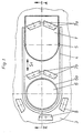
- Figs. 1 and 2 the entry and exit hatch of a combat vehicle, such as a battle tank is shown.
- the hatch may be located at the top of the vehicle sump or at the tower.
- a hatch cover 1 is arranged, which is displaceable parallel to the closing plane of the hatch opening 6 in the direction of the arrow S 1.
- rails 4 are arranged on both sides of the hatch cover 1, in which connected to the hatch cover 1 rollers 5 are guided.
- the devices for moving the hatch cover 1 are not specifically shown. The displacement can be done in principle by hand or by motor, and the devices necessary for this purpose can be arranged on or in the hatch cover 1.
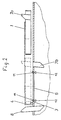
- the hatch viewing devices are arranged, of which the viewing devices 8 are outside the displacement path of the hatch cover 1 and are each constructed as a unit. Further vision devices are located in the displacement track of the hatch cover 1. These vision devices are divided into vehicle-fixed lower parts 7b and built into the hatch cover 1 and with this movable upper parts 7a. In the closed position of the hatch cover 1, the upper parts 7a and the lower parts 7b of the viewing devices are arranged in alignment with each other and in optical contact. In the edge region 6a of the hatch opening 6, a sealing device is arranged, which is not shown in Fig. 1 and in Fig. 2 only indicated and will be explained in more detail below with reference to FIGS. 3A, 3B and 4A, 4B.
- the sealing device has a arranged in the edge region of the hatch opening 6 flat outer ring 9, which rests in a connected to the armor 3 by welding receiving ring 9.1.
- a substantially cylindrical inner ring 10 is guided, which is displaceable in a direction S2 perpendicular to the closing plane of the hatch opening 6.
- a sealing ring 11 is arranged such that its upper edge is located both in the raised and in the lowered position above the inner ring 10 and the outer ring 9.
- the sealing ring 11 is vulcanized to a arranged on the inside of the inner ring fixing strip 10.1.
- the sealing ring 11 On its outer side, the sealing ring 11 has an outwardly extending annular sealing tabs 11.1, which is vulcanized to the outer ring 9 overlapping the upper edge of the inner ring 10 and the parting line between inner ring 10 and outer ring 9.
- the raising and lowering of the inner ring 10 is done with a displacement device which is designed in the manner of a quick release with a disposed below the inner ring 10 rotatable plate 12.1, which has on its inner ring 10 facing upper side in the circumferential direction wedge-shaped surface.
- the actuation takes place via a rotary knob 12.2.
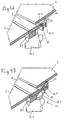
- FIGS. 3A and 3B and 4A and 4B The operation of the sealing device can be read from FIGS. 3A and 3B and 4A and 4B.
- Figs. 3A and 4A the sealing device is shown in the open state of the hatch, while it is shown in Figs. 3B and 4B in the closed state.
- the hatch cover 1 As shown in Fig. 3B and 4 B, is moved to the closed position in which it is above the hatch opening 6, 12 of the distributed at the periphery of the hatch opening 6 displacement devices 12 of the inner ring 10 is raised by turning the knobs 12.2 until the sealing ring 11 seals against the underside of the hatch cover 1.
- the displacement movement of the inner ring 10 can be achieved by a rotation of the knobs 12.2, which is smaller than 360 °.
- the opening and closing of the sealing device is carried out quickly and with little effort.
- the closed state of the hatch cover 1 and the sealing device is by the concerns of the sealing ring 11 on the underside of the hatch cover 1 and the dense, produced by scorching connection between the sealing ring 11 and the inner ring 10 and the sealing flaps 11.1 and the outer ring 9 is a very good seal reached.
Landscapes
- Engineering & Computer Science (AREA)
- Mechanical Engineering (AREA)
- General Engineering & Computer Science (AREA)
- Closures For Containers (AREA)
- Specific Sealing Or Ventilating Devices For Doors And Windows (AREA)
- Pressure Vessels And Lids Thereof (AREA)
- Filling Or Discharging Of Gas Storage Vessels (AREA)
- Organic Low-Molecular-Weight Compounds And Preparation Thereof (AREA)
Description
- Die Erfindung betrifft eine Ein-Ausstiegsluke für ein Kampffahrzeug, insbesondere einen Kampfpanzer mit den Merkmalen aus dem Oberbegriff des Patentanspruchs 1.
- Eine derartige Ein-Ausstiegsluke ist in DE 33 05 882 C2 beschrieben. Diese bekannte Ein-Ausstiegsluke besitzt eine Dichtungseinrichtung mit einem in der Lukenöffnung angeordneten zylindrischen Ring, der an seiner äußeren Mantelfläche ein Außengewinde aufweist, welches in ein in der Lukenöffnung angeordnetes Innengewinde eingreift. Mit Hilfe von am unteren Ende des Ringes angeordneten Handgriffen kann dieser aufwärts und abwärts geschraubt und damit angehoben oder abgesenkt werden. In der angehobenen Stellung legt sich der obere Rand des zylindrischen Rings dichtend an die Unterseite des Lukendeckels an.
- Bei dieser bekannten Ein- und Ausstiegsluke ist die Bedienung der Dichtungsvorrichtung von innen relativ mühsam und eine einwandfreie Dichtung der Luke, die im geschlossenen Zustand wasser- und ABC-dicht sein soll, schwer zu erreichen.
- Der Erfindung liegt die Aufgabe zugrunde, eine Ein-Ausstiegsluke mit den im Oberbegriff des Patentanspruchs 1 angegebenen Merkmalen so auszugestalten, dass die Dichtungsvorrichtung einfach aufgebaut, leicht zu bedienen und außerordentlich wirksam in der Abdichtung ist.
- Die Lösung dieser Aufgabe erfolgt erfindungsgemäß mit den Merkmalen aus dem kennzeichnenden Teil des Patentanspruchs 1. Vorteilhafte Weiterbildungen der Erfindung sind in den abhängigen Ansprüchen beschrieben.
- Der Grundgedanke der Erfindung besteht darin, die Dichtungsvorrichtung im wesentlichen mit drei Bauteilen aufzubauen, nämlich einem im Randbereich der Lukenöffnung fest angeordneten flachen Außenring, einem zylindrischen Innenring, der am Innenrand des Außenrings geführt und senkrecht zur Schließebene der Luke verschiebbar ist, und einem Dichtungsring, der an der Innenseite des Innenrings befestigt ist und mit diesem zusammen aus einer abgesenkten Stellung in eine angehobene Dichtungsstellung anhebbar ist, in welche er sich an die Unterseite des geschlossenen Lukendeckels dichtend anlegt.
- Zur Erzielung einer besonders guten Abdichtung kann der Dichtungsring an den Innenring anvulkanisiert sein und einen sich von seiner Außenseite nach außen erstreckenden Dichtungslappen aufweisen, welcher die Oberseite des Innenrings sowie die ringförmige Trennfuge zwischen Innenring und Außenring überdeckend an den Außenring anvulkanisiert ist. Die Verschiebungsvorrichtung kann in der Art eines Schnellverschlusses ausgebildet sein mit einer unterhalb des Innenrings angeordneten, manuell drehbaren Platte, die an der dem Innenring zugewandten Oberseite eine in Umfangsrichtung keilförmig ansteigende Oberfläche besitzt. Mit dieser Verschiebungsvorrichtung kann mit wenigen Handgriffen und einer Drehung von weniger als 360° der Innenring und damit der Dichtungsring in die gewünschte Dichtungsstellung angehoben werden. Damit ist die Bedienung der Dichtungseinrichtung erheblich vereinfacht.
- Im folgenden wird anhand der beigefügten Zeichnungen ein Ausführungsbeispiel für eine Ein-Ausstiegsluke nach der Erfindung näher erläutert.
- In den Zeichnungen zeigen:
- Fig. 1
- eine Aufsicht auf eine mit einem Lukendeckel verschließbare Ein- und Ausstiegsluke eines Kampffahrzeugs;
- Fig. 2
- einen Schnitt nach der Linie II-II im geöffneten Zustand der Luke;
- Fig. 3A und 3B
- einen gegenüber Fig. 2 stärker vergrößerten vertikalen Teilschnitt durch den Randbereich der Lukenöffnung der Luke nach Fig. 1 und 2 jeweils im geöffneten und geschlossenen Zustand der Luke;
- Fig. 4A und 4B
- die in den Fig. 3A und 3B dargestellten Teile in isometrischer Darstellung.
- In den Fig. 1 und 2 ist die Ein- und Ausstiegsluke eines Kampffahrzeugs, beispielsweise eines Kampfpanzers dargestellt. Die Luke kann sich an der Oberseite der Fahrzeugwanne oder am Turm befinden.
- Oberhalb der von der Panzerung 3 umgebenen Lukenöffnung 6 ist ein Lukendeckel 1 angeordnet, der parallel zur Schließebene der Lukenöffnung 6 in Pfeilrichtung S 1 verschiebbar ist. Hierzu sind zu beiden Seiten des Lukendeckels 1 Schienen 4 angeordnet, in denen mit dem Lukendeckel 1 verbundene Laufrollen 5 geführt sind. Die Vorrichtungen zum Verschieben des Lukendeckels 1 sind nicht eigens dargestellt. Die Verschiebung kann prinzipiell von Hand oder motorisch erfolgen, und die hierzu notwendigen Vorrichtungen können am oder im Lukendeckel 1 angeordnet sein.
- Im Bereich der Luke sind Sichtgeräte angeordnet, von denen sich die Sichtgeräte 8 außerhalb der Verschiebungsbahn des Lukendeckels 1 befinden und jeweils als eine Einheit aufgebaut sind. Weitere Sichtgeräte befinden sich in der Verschiebungsbahn des Lukendeckels 1. Diese Sichtgeräte sind aufgeteilt in fahrzeugfeste Unterteile 7b und in den Lukendeckel 1 eingebaute und mit diesem verschiebbare Oberteile 7a. In der Schließstellung des Lukendeckels 1 sind die Oberteile 7a und die Unterteile 7b der Sichtgeräte fluchtend zueinander und in optischem Kontakt angeordnet. Im Randbereich 6a der Lukenöffnung 6 ist eine Dichtungsvorrichtung angeordnet, die in Fig. 1 nicht und in Fig. 2 nur angedeutet dargestellt ist und im folgenden anhand der Fig. 3A, 3B sowie 4A, 4B näher erläutert wird.
- Die Dichtungsvorrichtung besitzt einen im Randbereich der Lukenöffnung 6 angeordneten flachen Außenring 9, der in einem mit der Panzerung 3 durch Schweißung verbundenen Aufnahmering 9.1 ruht. Am Innenrand des Außenrings 9 ist ein im wesentlichen zylindrischer Innenring 10 geführt, der in einer Richtung S2 senkrecht zur Schließebene der Lukenöffnung 6 verschiebbar ist. Am Innenring 10 ist ein Dichtungsring 11 derart angeordnet, dass seine Oberkante sowohl in der angehobenen als auch in der abgesenkten Stellung oberhalb des Innenrings 10 und des Außenrings 9 liegt. Der Dichtungsring 11 ist an eine an der Innenseite des Innenrings angeordnete Befestigungsleiste 10.1 anvulkanisiert. An seiner Außenseite besitzt der Dichtungsring 11 einen sich nach außen erstreckenden ringförmigen Dichtungslappen 11.1, der die Oberkante des Innenrings 10 sowie die Trennfuge zwischen Innenring 10 und Außenring 9 überdeckend an den Außenring 9 anvulkanisiert ist.
- Das Anheben und Absenken des Innenrings 10 geschieht mit einer Verschiebungsvorrichtung, die nach Art eines Schnellverschlusses ausgebildet ist mit einer unterhalb des Innenrings 10 angeordneten drehbaren Platte 12.1, die an ihrer dem Innenring 10 zugewandten Oberseite eine in Umfangsrichtung keilförmig ansteigende Oberfläche aufweist. Die Betätigung erfolgt über einen Drehknopf 12.2.
- Die Wirkungsweise der Dichtungsvorrichtung ist aus den Fig. 3A bzw. 3B und 4A bzw. 4B ablesbar. In den Fig. 3A und 4A ist die Dichtungsvorrichtung im geöffneten Zustand der Luke dargestellt, während sie in den Fig. 3B und 4B im geschlossenen Zustand dargestellt ist. Wenn der Lukendeckel 1, wie in Fig. 3B und 4 B dargestellt, in die Geschlossenstellung verschoben ist, in der er oberhalb der Lukenöffnung 6 liegt, wird durch Drehen an den Drehknöpfen 12.2 der am Umfang der Lukenöffnung 6 verteilten Verschiebungsvorrichtungen 12 der Innenring 10 angehoben, bis sich der Dichtungsring 11 an die Unterseite des Lukendeckels 1 dichtend anlegt. Die Verschiebungsbewegung des Innenrings 10 kann dabei durch eine Drehung der Drehknöpfe 12.2 erzielt werden, die kleiner als 360° ist. Somit ist das Öffnen und Schließen der Dichtungsvorrichtung rasch und mit wenig Aufwand durchführbar. Im geschlossenen Zustand des Lukendeckels 1 und der Dichtungseinrichtung ist durch das Anliegen des Dichtungsrings 11 an der Unterseite des Lukendeckels 1 und die dichte, durch Anvulkanisieren erzeugte Verbindung zwischen dem Dichtungsring 11 und dem Innenring 10 sowie dem Dichtungslappen 11.1 und dem Außenring 9 eine sehr gute Abdichtung erreicht.
- Aufgrund der oben erläuterten Verriegelung der Dichtungsvorrichtung mittels der am Umfang der Lukenöffnung verteilten, durch die Drehknöpfe 12.2 betätigten Verschiebungsvorrichtungen 12 ist es nicht mehr notwendig, die Dichtung kreisförmig auszubilden. Sie kann auch andere Formen annehmen.
Claims (4)
- Ein-Ausstiegsluke für ein Kampffahrzeug, insbesondere einen Kampfpanzer, mit einem Lukendeckel (1), der oberhalb des oberen Randes der Lukenöffnung (6) angeordnet ist und zum Öffnen und Schließen parallel zur Schließebene der Luke verschiebbar ist, und mit einer in der Lukenöffnung (6) senkrecht zur Schließebene bewegbar angeordneten Dichtungsvorrichtung, die in eine Öffnungsstellung soweit absenkbar ist, dass der Lukendeckel (1) unbehindert verschiebbar ist, während sie in eine Schließstellung soweit anhebbar ist, dass ihr oberer Rand dichtend an der Unterseite des Lukendeckels (1) liegt, dadurch gekennzeichnet, dass die Dichtungsvorrichtung einen im Randbereich (6a) der Lukenöffnung (6) fest angeordneten flachen Außenring (9) aufweist, an dessen Innenrand ein zylindrischer Innenring (10) senkrecht (S2) zur Schließebene verschiebbar geführt ist, und an der Innenseite des Innenrings (10) ein Dichtungsring (11) derart angeordnet ist, dass seine Oberkante oberhalb der Oberkante des Innenrings (10) und des Außenrings (9) liegt und der Innenring (10) mittels mehrerer über seinen Umfang verteilt angeordneter, manuell betätigbarer Verschiebungsvorrichtungen (12) aus der Öffnungsstellung derart in die Schließstellung verschiebbar ist, dass die Oberkante des Dichtungsrings (11) dichtend an der Unterseite des geschlossenen Lukendeckels (1) anliegt.
- Ein-Ausstiegsluke nach Anspruch 1, dadurch gekennzeichnet, dass der Dichtungsring (11) an eine an der Innenseite des Innenrings (10) angeordnete Befestigungsleiste (10.1) anvulkanisiert ist.
- Ein-Ausstiegsluke nach Anspruch 1 oder 2, dadurch gekennzeichnet, dass der Dichtungsring (11) an seiner Außenseite einen ringförmigen Dichtungslappen (11.1) aufweist, der die Oberkante des Innenrings (10) und die Trennfuge zwischen Innenring (10) und Außenring (9) überdeckend dichtend mit dem Außenring (9) verbunden ist.
- Ein-Ausstiegsluke nach einem der Ansprüche 1 bis 3, dadurch gekennzeichnet, dass die Verschiebungsvorrichtung (12) eine unterhalb des Innenrings (10) angeordnete, manuell drehbare Platte (12.1) aufweist, die an der dem Innenring zugewandten Oberseite eine in Umfangsrichtung keilförmig ansteigende Oberfläche besitzt.
Priority Applications (1)
| Application Number | Priority Date | Filing Date | Title |
|---|---|---|---|
| PL04024904T PL1528352T3 (pl) | 2003-11-03 | 2004-10-20 | Właz wejściowo-wyjściowy dla pojazdu bojowego, zwłaszcza wozu bojowego |
Applications Claiming Priority (2)
| Application Number | Priority Date | Filing Date | Title |
|---|---|---|---|
| DE20316836U | 2003-11-03 | ||
| DE20316836U DE20316836U1 (de) | 2003-11-03 | 2003-11-03 | Ein-Ausstiegsluke für ein Kampffahrzeug, insbesondere einen Kampfpanzer |
Publications (2)
| Publication Number | Publication Date |
|---|---|
| EP1528352A1 EP1528352A1 (de) | 2005-05-04 |
| EP1528352B1 true EP1528352B1 (de) | 2006-05-10 |
Family
ID=30470109
Family Applications (1)
| Application Number | Title | Priority Date | Filing Date |
|---|---|---|---|
| EP04024904A Expired - Lifetime EP1528352B1 (de) | 2003-11-03 | 2004-10-20 | Ein-Ausstiegsluke für ein Kampffahrzeug, insbesondere einen Kampfpanzer |
Country Status (7)
| Country | Link |
|---|---|
| EP (1) | EP1528352B1 (de) |
| AT (1) | ATE326002T1 (de) |
| DE (2) | DE20316836U1 (de) |
| DK (1) | DK1528352T3 (de) |
| ES (1) | ES2262080T3 (de) |
| NO (1) | NO20044719L (de) |
| PL (1) | PL1528352T3 (de) |
Families Citing this family (2)
| Publication number | Priority date | Publication date | Assignee | Title |
|---|---|---|---|---|
| DE102004059016B4 (de) * | 2004-12-08 | 2007-03-08 | Rheinmetall Landsysteme Gmbh | Vorrichtung zum Öffnen und Schließen eines Lukendeckels, insbesondere für ein gepanzertes Fahrzeug |
| DE202005000199U1 (de) * | 2005-01-07 | 2006-05-24 | Krauss-Maffei Wegmann Gmbh & Co. Kg | Dichtungsvorrichtung für eine Ein-Ausstiegsluke an einem Kampffahrzeug |
Family Cites Families (4)
| Publication number | Priority date | Publication date | Assignee | Title |
|---|---|---|---|---|
| DE3305882A1 (de) * | 1983-02-19 | 1984-08-23 | Wegmann & Co GmbH, 3500 Kassel | Kampffahrzeug, insbesondere kampfpanzer |
| GB8618944D0 (en) * | 1986-08-02 | 1986-09-10 | Winsford Techn Ltd | Autoclave sealing |
| DE4240140A1 (de) * | 1992-11-28 | 1994-06-01 | Wegmann & Co Gmbh | Vorrichtung zum Öffnen und Schließen eines Lukendeckels an einem Kampffahrzeug, insbesondere einem Kampfpanzer |
| DE19504922C2 (de) * | 1994-02-17 | 1996-07-04 | Wegmann & Co Gmbh | Ein-Ausstiegsluke für ein Kampffahrzeug, insbesondere einen Kampfpanzer |
-
2003
- 2003-11-03 DE DE20316836U patent/DE20316836U1/de not_active Expired - Lifetime
-
2004
- 2004-10-20 AT AT04024904T patent/ATE326002T1/de not_active IP Right Cessation
- 2004-10-20 EP EP04024904A patent/EP1528352B1/de not_active Expired - Lifetime
- 2004-10-20 PL PL04024904T patent/PL1528352T3/pl unknown
- 2004-10-20 DK DK04024904T patent/DK1528352T3/da active
- 2004-10-20 ES ES04024904T patent/ES2262080T3/es not_active Expired - Lifetime
- 2004-10-20 DE DE502004000532T patent/DE502004000532D1/de not_active Expired - Lifetime
- 2004-11-01 NO NO20044719A patent/NO20044719L/no not_active Application Discontinuation
Also Published As
| Publication number | Publication date |
|---|---|
| DE20316836U1 (de) | 2004-01-15 |
| PL1528352T3 (pl) | 2006-08-31 |
| ATE326002T1 (de) | 2006-06-15 |
| DK1528352T3 (da) | 2006-08-28 |
| NO20044719L (no) | 2005-05-04 |
| EP1528352A1 (de) | 2005-05-04 |
| DE502004000532D1 (de) | 2006-06-14 |
| ES2262080T3 (es) | 2006-11-16 |
Similar Documents
| Publication | Publication Date | Title |
|---|---|---|
| DE3305882C2 (de) | ||
| EP0110037B1 (de) | Kampffahrzeug, insbesondere Kampfpanzer | |
| WO1985002593A1 (fr) | Recipient, en particulier pour une installation de transport | |
| EP0540848B1 (de) | Drehringlafette für eine leichte Waffe an einem Kampffahrzeug, insbesondere an einer Luke eines Kampfpanzers | |
| DE1575424A1 (de) | Vorrichtung zum Verhindern der Ablagerung von Staub auf den Fuehrungsschienen einer Praezisionsapparatur | |
| DE1509994B1 (de) | Fuehrungsvorrichtung fuer Schiebetueren | |
| EP1528352B1 (de) | Ein-Ausstiegsluke für ein Kampffahrzeug, insbesondere einen Kampfpanzer | |
| DE102004036842A1 (de) | Ein-Ausstiegsluke für ein Kampffahrzeug, insbesondere einen Kampfpanzer | |
| DE3022320C2 (de) | ||
| DE2004907A1 (de) | Vorrichtung zum Regeln der Durchflußmenge eines flüssigen Metalls | |
| DE2845223C2 (de) | ||
| DE4136185C2 (de) | Lukenabdeckung, insbesondere für Kampffahrzeuge | |
| DE1948440C3 (de) | Schleuse zum Einbringen von Schüttgütern in gasdicht abgeschlossene Räume, insbesondere von Legierungselementen in Stahlentgasungsgefäße | |
| DE10337005A1 (de) | Ein-Ausstiegsluke für ein Kampffahrzeug, insbesondere einen Kampfpanzer | |
| DE10315797B4 (de) | Verschlussmechanismus für ein Behältnis mit Deckel | |
| DE3049474A1 (de) | Vorrichtung zum verfahren des loesbaren daches eines personenkraftwagens | |
| DE202004014186U1 (de) | Schwenktür für Fahrzeuge des öffentlichen Personenverkehrs, insbesondere für Busse | |
| EP1679216B1 (de) | Dichtungsvorrichtung für eine Ein-Ausstiegsluke an einem Kampffahrzeug | |
| DE3116641A1 (de) | Fahrerschutzkabine fuer fahrzeuge | |
| DE3237226A1 (de) | Anpressbares schiebefenster | |
| DE19846159C1 (de) | Öffnungsfähiges Fahrzeugdach mit einem kippbarem Deckel zum Verschließen und Freigeben einer kreisförmigen Dachöffnung | |
| DE2252861A1 (de) | Verschlussanordnung fuer oeffnungen | |
| EP0004004A1 (de) | Einrichtung an einer Rauchsammelkammer für ein metallurgisches Gefäss | |
| DE3739127A1 (de) | Nutzfahrzeug mit fahrerhaus | |
| DE19923976A1 (de) | Führungs- und Abschirmvorrichtung für eine Schiebeplane |
Legal Events
| Date | Code | Title | Description |
|---|---|---|---|
| PUAI | Public reference made under article 153(3) epc to a published international application that has entered the european phase |
Free format text: ORIGINAL CODE: 0009012 |
|
| AK | Designated contracting states |
Kind code of ref document: A1 Designated state(s): AT BE BG CH CY CZ DE DK EE ES FI FR GB GR HU IE IT LI LU MC NL PL PT RO SE SI SK TR |
|
| AX | Request for extension of the european patent |
Extension state: AL HR LT LV MK |
|
| 17P | Request for examination filed |
Effective date: 20050502 |
|
| GRAP | Despatch of communication of intention to grant a patent |
Free format text: ORIGINAL CODE: EPIDOSNIGR1 |
|
| AKX | Designation fees paid |
Designated state(s): AT BE BG CH CY CZ DE DK EE ES FI FR GB GR HU IE IT LI LU MC NL PL PT RO SE SI SK TR |
|
| GRAS | Grant fee paid |
Free format text: ORIGINAL CODE: EPIDOSNIGR3 |
|
| GRAA | (expected) grant |
Free format text: ORIGINAL CODE: 0009210 |
|
| AK | Designated contracting states |
Kind code of ref document: B1 Designated state(s): AT BE BG CH CY CZ DE DK EE ES FI FR GB GR HU IE IT LI LU MC NL PL PT RO SE SI SK TR |
|
| PG25 | Lapsed in a contracting state [announced via postgrant information from national office to epo] |
Ref country code: IT Free format text: LAPSE BECAUSE OF FAILURE TO SUBMIT A TRANSLATION OF THE DESCRIPTION OR TO PAY THE FEE WITHIN THE PRESCRIBED TIME-LIMIT;WARNING: LAPSES OF ITALIAN PATENTS WITH EFFECTIVE DATE BEFORE 2007 MAY HAVE OCCURRED AT ANY TIME BEFORE 2007. THE CORRECT EFFECTIVE DATE MAY BE DIFFERENT FROM THE ONE RECORDED. Effective date: 20060510 Ref country code: SI Free format text: LAPSE BECAUSE OF FAILURE TO SUBMIT A TRANSLATION OF THE DESCRIPTION OR TO PAY THE FEE WITHIN THE PRESCRIBED TIME-LIMIT Effective date: 20060510 Ref country code: IE Free format text: LAPSE BECAUSE OF FAILURE TO SUBMIT A TRANSLATION OF THE DESCRIPTION OR TO PAY THE FEE WITHIN THE PRESCRIBED TIME-LIMIT Effective date: 20060510 |
|
| REG | Reference to a national code |
Ref country code: GB Ref legal event code: FG4D Free format text: NOT ENGLISH |
|
| REG | Reference to a national code |
Ref country code: CH Ref legal event code: EP |
|
| GBT | Gb: translation of ep patent filed (gb section 77(6)(a)/1977) |
Effective date: 20060510 |
|
| REG | Reference to a national code |
Ref country code: CH Ref legal event code: NV Representative=s name: A. BRAUN, BRAUN, HERITIER, ESCHMANN AG PATENTANWAE |
|
| REF | Corresponds to: |
Ref document number: 502004000532 Country of ref document: DE Date of ref document: 20060614 Kind code of ref document: P |
|
| REG | Reference to a national code |
Ref country code: IE Ref legal event code: FG4D Free format text: LANGUAGE OF EP DOCUMENT: GERMAN |
|
| REG | Reference to a national code |
Ref country code: RO Ref legal event code: EPE |
|
| REG | Reference to a national code |
Ref country code: SE Ref legal event code: TRGR |
|
| REG | Reference to a national code |
Ref country code: DK Ref legal event code: T3 |
|
| REG | Reference to a national code |
Ref country code: GR Ref legal event code: EP Ref document number: 20060402442 Country of ref document: GR |
|
| PG25 | Lapsed in a contracting state [announced via postgrant information from national office to epo] |
Ref country code: PT Free format text: LAPSE BECAUSE OF FAILURE TO SUBMIT A TRANSLATION OF THE DESCRIPTION OR TO PAY THE FEE WITHIN THE PRESCRIBED TIME-LIMIT Effective date: 20061010 |
|
| PGFP | Annual fee paid to national office [announced via postgrant information from national office to epo] |
Ref country code: RO Payment date: 20061013 Year of fee payment: 3 |
|
| PG25 | Lapsed in a contracting state [announced via postgrant information from national office to epo] |
Ref country code: MC Free format text: LAPSE BECAUSE OF NON-PAYMENT OF DUE FEES Effective date: 20061031 |
|
| REG | Reference to a national code |
Ref country code: ES Ref legal event code: FG2A Ref document number: 2262080 Country of ref document: ES Kind code of ref document: T3 |
|
| ET | Fr: translation filed | ||
| REG | Reference to a national code |
Ref country code: IE Ref legal event code: FD4D |
|
| PLBE | No opposition filed within time limit |
Free format text: ORIGINAL CODE: 0009261 |
|
| STAA | Information on the status of an ep patent application or granted ep patent |
Free format text: STATUS: NO OPPOSITION FILED WITHIN TIME LIMIT |
|
| REG | Reference to a national code |
Ref country code: HU Ref legal event code: AG4A Ref document number: E001120 Country of ref document: HU |
|
| 26N | No opposition filed |
Effective date: 20070213 |
|
| PGFP | Annual fee paid to national office [announced via postgrant information from national office to epo] |
Ref country code: CZ Payment date: 20071009 Year of fee payment: 4 Ref country code: DK Payment date: 20071023 Year of fee payment: 4 Ref country code: HU Payment date: 20071012 Year of fee payment: 4 |
|
| PGFP | Annual fee paid to national office [announced via postgrant information from national office to epo] |
Ref country code: FI Payment date: 20071019 Year of fee payment: 4 Ref country code: AT Payment date: 20071024 Year of fee payment: 4 Ref country code: PL Payment date: 20071008 Year of fee payment: 4 Ref country code: SK Payment date: 20071012 Year of fee payment: 4 |
|
| PGFP | Annual fee paid to national office [announced via postgrant information from national office to epo] |
Ref country code: BE Payment date: 20071022 Year of fee payment: 4 |
|
| REG | Reference to a national code |
Ref country code: CH Ref legal event code: PFA Owner name: KRAUSS-MAFFEI WEGMANN GMBH & CO. KG Free format text: KRAUSS-MAFFEI WEGMANN GMBH & CO. KG#AUGUST-BODE-STRASSE 1#34127 KASSEL (DE) -TRANSFER TO- KRAUSS-MAFFEI WEGMANN GMBH & CO. KG#AUGUST-BODE-STRASSE 1#34127 KASSEL (DE) |
|
| PG25 | Lapsed in a contracting state [announced via postgrant information from national office to epo] |
Ref country code: EE Free format text: LAPSE BECAUSE OF FAILURE TO SUBMIT A TRANSLATION OF THE DESCRIPTION OR TO PAY THE FEE WITHIN THE PRESCRIBED TIME-LIMIT Effective date: 20060510 |
|
| PGFP | Annual fee paid to national office [announced via postgrant information from national office to epo] |
Ref country code: TR Payment date: 20071005 Year of fee payment: 4 |
|
| PG25 | Lapsed in a contracting state [announced via postgrant information from national office to epo] |
Ref country code: LU Free format text: LAPSE BECAUSE OF NON-PAYMENT OF DUE FEES Effective date: 20061020 Ref country code: BG Free format text: LAPSE BECAUSE OF NON-PAYMENT OF DUE FEES Effective date: 20070430 |
|
| PG25 | Lapsed in a contracting state [announced via postgrant information from national office to epo] |
Ref country code: RO Free format text: LAPSE BECAUSE OF NON-PAYMENT OF DUE FEES Effective date: 20071020 Ref country code: CY Free format text: LAPSE BECAUSE OF FAILURE TO SUBMIT A TRANSLATION OF THE DESCRIPTION OR TO PAY THE FEE WITHIN THE PRESCRIBED TIME-LIMIT Effective date: 20060510 |
|
| BERE | Be: lapsed |
Owner name: *KRAUSS-MAFFEI WEGMANN G.M.B.H. & CO. K.G. Effective date: 20081031 |
|
| REG | Reference to a national code |
Ref country code: DK Ref legal event code: EBP |
|
| NLV4 | Nl: lapsed or anulled due to non-payment of the annual fee |
Effective date: 20090501 |
|
| PG25 | Lapsed in a contracting state [announced via postgrant information from national office to epo] |
Ref country code: FI Free format text: LAPSE BECAUSE OF NON-PAYMENT OF DUE FEES Effective date: 20081020 Ref country code: NL Free format text: LAPSE BECAUSE OF NON-PAYMENT OF DUE FEES Effective date: 20090501 |
|
| PG25 | Lapsed in a contracting state [announced via postgrant information from national office to epo] |
Ref country code: AT Free format text: LAPSE BECAUSE OF NON-PAYMENT OF DUE FEES Effective date: 20081020 Ref country code: CZ Free format text: LAPSE BECAUSE OF NON-PAYMENT OF DUE FEES Effective date: 20081020 |
|
| PG25 | Lapsed in a contracting state [announced via postgrant information from national office to epo] |
Ref country code: BE Free format text: LAPSE BECAUSE OF NON-PAYMENT OF DUE FEES Effective date: 20081031 Ref country code: SK Free format text: LAPSE BECAUSE OF NON-PAYMENT OF DUE FEES Effective date: 20081020 |
|
| PG25 | Lapsed in a contracting state [announced via postgrant information from national office to epo] |
Ref country code: DK Free format text: LAPSE BECAUSE OF NON-PAYMENT OF DUE FEES Effective date: 20081031 Ref country code: HU Free format text: LAPSE BECAUSE OF NON-PAYMENT OF DUE FEES Effective date: 20081021 |
|
| PG25 | Lapsed in a contracting state [announced via postgrant information from national office to epo] |
Ref country code: GR Free format text: LAPSE BECAUSE OF NON-PAYMENT OF DUE FEES Effective date: 20090505 |
|
| PG25 | Lapsed in a contracting state [announced via postgrant information from national office to epo] |
Ref country code: PL Free format text: LAPSE BECAUSE OF NON-PAYMENT OF DUE FEES Effective date: 20081020 |
|
| REG | Reference to a national code |
Ref country code: PL Ref legal event code: LAPE |
|
| PG25 | Lapsed in a contracting state [announced via postgrant information from national office to epo] |
Ref country code: TR Free format text: LAPSE BECAUSE OF NON-PAYMENT OF DUE FEES Effective date: 20100917 |
|
| PG25 | Lapsed in a contracting state [announced via postgrant information from national office to epo] |
Ref country code: TR Free format text: LAPSE BECAUSE OF NON-PAYMENT OF DUE FEES Effective date: 20081020 |
|
| REG | Reference to a national code |
Ref country code: CH Ref legal event code: PCAR Free format text: NEW ADDRESS: HOLBEINSTRASSE 36-38, 4051 BASEL (CH) |
|
| REG | Reference to a national code |
Ref country code: FR Ref legal event code: PLFP Year of fee payment: 12 |
|
| REG | Reference to a national code |
Ref country code: FR Ref legal event code: PLFP Year of fee payment: 13 |
|
| REG | Reference to a national code |
Ref country code: FR Ref legal event code: PLFP Year of fee payment: 14 |
|
| REG | Reference to a national code |
Ref country code: FR Ref legal event code: PLFP Year of fee payment: 15 |
|
| PGFP | Annual fee paid to national office [announced via postgrant information from national office to epo] |
Ref country code: DE Payment date: 20181031 Year of fee payment: 15 Ref country code: SE Payment date: 20181025 Year of fee payment: 15 |
|
| PGFP | Annual fee paid to national office [announced via postgrant information from national office to epo] |
Ref country code: ES Payment date: 20181122 Year of fee payment: 15 Ref country code: GB Payment date: 20181025 Year of fee payment: 15 Ref country code: IT Payment date: 20181022 Year of fee payment: 15 Ref country code: FR Payment date: 20181023 Year of fee payment: 15 Ref country code: CH Payment date: 20181025 Year of fee payment: 15 |
|
| REG | Reference to a national code |
Ref country code: DE Ref legal event code: R119 Ref document number: 502004000532 Country of ref document: DE |
|
| REG | Reference to a national code |
Ref country code: CH Ref legal event code: PL |
|
| PG25 | Lapsed in a contracting state [announced via postgrant information from national office to epo] |
Ref country code: LI Free format text: LAPSE BECAUSE OF NON-PAYMENT OF DUE FEES Effective date: 20191031 Ref country code: CH Free format text: LAPSE BECAUSE OF NON-PAYMENT OF DUE FEES Effective date: 20191031 Ref country code: DE Free format text: LAPSE BECAUSE OF NON-PAYMENT OF DUE FEES Effective date: 20200501 |
|
| PG25 | Lapsed in a contracting state [announced via postgrant information from national office to epo] |
Ref country code: SE Free format text: LAPSE BECAUSE OF NON-PAYMENT OF DUE FEES Effective date: 20191021 |
|
| GBPC | Gb: european patent ceased through non-payment of renewal fee |
Effective date: 20191020 |
|
| PG25 | Lapsed in a contracting state [announced via postgrant information from national office to epo] |
Ref country code: IT Free format text: LAPSE BECAUSE OF NON-PAYMENT OF DUE FEES Effective date: 20191020 Ref country code: GB Free format text: LAPSE BECAUSE OF NON-PAYMENT OF DUE FEES Effective date: 20191020 Ref country code: FR Free format text: LAPSE BECAUSE OF NON-PAYMENT OF DUE FEES Effective date: 20191031 |
|
| REG | Reference to a national code |
Ref country code: ES Ref legal event code: FD2A Effective date: 20210301 |
|
| PG25 | Lapsed in a contracting state [announced via postgrant information from national office to epo] |
Ref country code: ES Free format text: LAPSE BECAUSE OF NON-PAYMENT OF DUE FEES Effective date: 20191021 |