EP1528352A1 - Ein-Ausstiegsluke für ein Kampffahrzeug, insbesondere einen Kampfpanzer - Google Patents
Ein-Ausstiegsluke für ein Kampffahrzeug, insbesondere einen Kampfpanzer Download PDFInfo
- Publication number
- EP1528352A1 EP1528352A1 EP04024904A EP04024904A EP1528352A1 EP 1528352 A1 EP1528352 A1 EP 1528352A1 EP 04024904 A EP04024904 A EP 04024904A EP 04024904 A EP04024904 A EP 04024904A EP 1528352 A1 EP1528352 A1 EP 1528352A1
- Authority
- EP
- European Patent Office
- Prior art keywords
- ring
- hatch
- inner ring
- sealing
- upper edge
- Prior art date
- Legal status (The legal status is an assumption and is not a legal conclusion. Google has not performed a legal analysis and makes no representation as to the accuracy of the status listed.)
- Granted
Links
- 238000007789 sealing Methods 0.000 claims abstract description 40
- 238000006073 displacement reaction Methods 0.000 claims description 10
- 230000000630 rising effect Effects 0.000 abstract description 3
- 230000001419 dependent effect Effects 0.000 description 1
- 238000011161 development Methods 0.000 description 1
- 230000018109 developmental process Effects 0.000 description 1
- 230000003287 optical effect Effects 0.000 description 1
- XLYOFNOQVPJJNP-UHFFFAOYSA-N water Substances O XLYOFNOQVPJJNP-UHFFFAOYSA-N 0.000 description 1
- 238000003466 welding Methods 0.000 description 1
Images


Classifications
-
- F—MECHANICAL ENGINEERING; LIGHTING; HEATING; WEAPONS; BLASTING
- F41—WEAPONS
- F41H—ARMOUR; ARMOURED TURRETS; ARMOURED OR ARMED VEHICLES; MEANS OF ATTACK OR DEFENCE, e.g. CAMOUFLAGE, IN GENERAL
- F41H5/00—Armour; Armour plates
- F41H5/22—Manhole covers, e.g. on tanks; Doors on armoured vehicles or structures
- F41H5/223—Manhole covers specially adapted for armoured or fighting vehicles
-
- B—PERFORMING OPERATIONS; TRANSPORTING
- B60—VEHICLES IN GENERAL
- B60J—WINDOWS, WINDSCREENS, NON-FIXED ROOFS, DOORS, OR SIMILAR DEVICES FOR VEHICLES; REMOVABLE EXTERNAL PROTECTIVE COVERINGS SPECIALLY ADAPTED FOR VEHICLES
- B60J9/00—Devices not provided for in one of main groups B60J1/00 - B60J7/00
- B60J9/02—Entrance or exit closures other than windows, doors, or in roofs, e.g. emergency escape closures in vehicle bottom
Definitions
- the invention relates to an entry-exit hatch for a combat vehicle, in particular a battle tank with the features of the preamble of claim 1.
- Such an entry-hatch is described in DE 33 05 882 C2.
- This known An exit hatch has a sealing means with one in the hatch opening arranged cylindrical ring, on its outer lateral surface an external thread has, which engages in a arranged in the hatch opening internal thread. With the help of arranged at the bottom of the ring handles this can upwards and screwed down and raised or lowered. In the raised Position sets the upper edge of the cylindrical ring sealingly against the Underside of the hatch cover on.
- the invention is based on the object, a one-exit hatch with the in the preamble of the claim 1 specified characteristics in such a way that the Sealing device simple, easy to use and extremely effective is in the seal.
- the basic idea of the invention is essentially the sealing device build with three components, namely one in the edge region of the hatch opening fixed flat outer ring, a cylindrical inner ring, the inner edge out of the outer ring and is displaceable perpendicular to the closing plane of the hatch, and a sealing ring, which is attached to the inside of the inner ring and with this together from a lowered position in a raised sealing position can be raised is, in which he sealing himself to the underside of the closed hatch cover invests.
- the displacement device may be in the manner of a quick release be formed with a arranged below the inner ring, manually rotatable Plate, on the inner ring facing the top one in the circumferential direction has wedge-shaped rising surface.
- Figs. 1 and 2 the entry and exit hatch of a combat vehicle, for example a battle tank shown.
- the hatch can be at the top of the vehicle pan or at the tower.
- a hatch cover. 1 arranged parallel to the closing plane of the hatch opening 6 in the direction of arrow S1 displaced is.
- rails 4 are arranged on both sides of the hatch cover 1, in which connected to the hatch cover 1 rollers 5 are guided.
- the devices for moving the hatch cover 1 are not specifically shown. The postponement can be done in principle by hand or by motor, and the necessary for this Devices can be arranged on or in the hatch cover 1.
- the hatch viewing devices are arranged, of which the viewing devices 8 located outside the displacement track of the hatch cover 1 and each as a Unit are constructed. Other viewing devices are in the displacement path of the Hatch covers 1. These viewing devices are divided into vehicle-fixed lower parts 7b and in the hatch 1 built-in and displaceable with this upper parts 7a. In the Closed position of the hatch cover 1, the upper parts 7a and the lower parts 7b of Viewing devices aligned with each other and arranged in optical contact. At the edge 6 a of the hatch opening 6, a sealing device is arranged, which in Fig. 1 not shown in Fig. 2 only indicated and in the following with reference to FIG. 3A, 3B and 4A, 4B is explained in more detail.
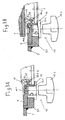
- the sealing device has a arranged in the edge region of the hatch opening 6 flat outer ring 9, which in one connected with the armor 3 by welding Pick ring 9.1 rests.
- On the inner edge of the outer ring 9 is a substantially cylindrical inner ring 10 is guided in a direction S2 perpendicular to Closing plane of the hatch opening 6 is displaceable.
- On the inner ring 10 is a sealing ring 11 arranged such that its upper edge both in the raised and in the lowered position above the inner ring 10 and the outer ring 9 is located.
- the Sealing ring 11 is attached to a arranged on the inside of the inner ring fixing strip 10.1 vulcanized.
- On its outer side the sealing ring has 11th an outwardly extending annular sealing lobe 11.1, the upper edge the inner ring 10 and the parting line between inner ring 10 and outer ring. 9 overlapping vulcanized to the outer ring 9.
- the lifting and lowering of the inner ring 10 is done with a displacement device, which is designed in the manner of a quick release with a below the Inner ring 10 arranged rotatable plate 12.1, facing the inner ring 10 at its Upper side has a wedge-shaped rising in the circumferential direction surface.
- the actuation takes place via a rotary knob 12.2.
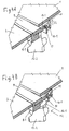
- FIGS. 3A and 3B and 4A and 4B The operation of the sealing device is shown in FIGS. 3A and 3B and 4A and 4B readable.
- the sealing device is in the opened state the hatch, while shown in Figs. 3B and 4B in the closed state is.
- the hatch 1 as shown in Fig. 3B and 4 B, in the closed position is moved, in which he lies above the hatch opening 6 is by rotating the knobs 12.2 distributed on the circumference of the hatch opening 6
- Displacement devices 12 of the inner ring 10 is raised until the sealing ring 11 to the underside of the hatch cover 1 sealingly applies.
- the displacement movement the inner ring 10 can be achieved by a rotation of the knobs 12.2, which is smaller than 360 °.
Landscapes
- Engineering & Computer Science (AREA)
- Mechanical Engineering (AREA)
- General Engineering & Computer Science (AREA)
- Closures For Containers (AREA)
- Specific Sealing Or Ventilating Devices For Doors And Windows (AREA)
- Pressure Vessels And Lids Thereof (AREA)
- Filling Or Discharging Of Gas Storage Vessels (AREA)
- Organic Low-Molecular-Weight Compounds And Preparation Thereof (AREA)
Abstract
Description
- Fig. 1
- eine Aufsicht auf eine mit einem Lukendeckel verschließbare Ein- und Ausstiegsluke eines Kampffahrzeugs;
- Fig. 2
- einen Schnitt nach der Linie II-II im geöffneten Zustand der Luke;
- Fig. 3A und 3B
- einen gegenüber Fig. 2 stärker vergrößerten vertikalen Teilschnitt durch den Randbereich der Lukenöffnung der Luke nach Fig. 1 und 2 jeweils im geöffneten und geschlossenen Zustand der Luke;
- Fig. 4A und 4B
- die in den Fig. 3A und 3B dargestellten Teile in isometrischer Darstellung.
Claims (4)
- Ein-Ausstiegsluke für ein Kampffahrzeug, insbesondere einen Kampfpanzer, mit einem Lukendeckel, der oberhalb des oberen Randes der Lukenöffnung angeordnet ist und zum Öffnen und Schließen parallel zur Schließebene der Luke verschiebbar ist, und mit einer in der Lukenöffnung senkrecht zur Schließebene bewegbar angeordneten Dichtungsvorrichtung, die in eine Öffnungsstellung soweit absenkbar ist, dass der Lukendeckel unbehindert verschiebbar ist, während sie in eine Schließstellung soweit anhebbar ist, dass ihr oberer Rand dichtend an der Unterseite des Lukendeckels liegt, dadurch gekennzeichnet, dass die Dichtungsvorrichtung einen im Randbereich (6a) der Lukenöffnung (6) fest angeordneten flachen Außenring (9) aufweist, an dessen Innenrand ein zylindrischer Innenring (10) senkrecht (S2) zur Schließebene verschiebbar geführt ist, und an der Innenseite des Innenrings (10) ein Dichtungsring (11) derart angeordnet ist, dass seine Oberkante oberhalb der Oberkante des Innenrings (10) und des Außenrings (9) liegt und der Innenring (10) mittels mehrerer über seinen Umfang verteilt angeordneter, manuell betätigbarer Verschiebungsvorrichtungen (12) aus der Öffnungsstellung derart in die Schließstellung verschiebbar ist, dass die Oberkante des Dichtungsrings (11) dichtend an der Unterseite des geschlossenen Lukendeckels (1) anliegt.
- Ein-Ausstiegsluke nach Anspruch 1, dadurch gekennzeichnet, dass der Dichtungsring (11) an eine an der Innenseite des Innenrings (10) angeordnete Befestigungsleiste (10.1) anvulkanisiert ist.
- Ein-Ausstiegsluke nach Anspruch 1 oder 2, dadurch gekennzeichnet, dass der Dichtungsring (11) an seiner Außenseite einen ringförmigen Dichtungslappen (11.1) aufweist, der die Oberkante des Innenrings (10) und die Trennfuge zwischen Innenring (10) und Außenring (9) überdeckend dichtend mit dem Außenring (9) verbunden ist.
- Ein-Ausstiegsluke nach einem der Ansprüche 1 bis 3, dadurch gekennzeichnet, dass die Verschiebungsvorrichtung (12) eine unterhalb des Innenrings (10) angeordnete, manuell drehbare Platte (12.1) aufweist, die an der dem Innenring zugewandten Oberseite eine in Umfangsrichtung keilförmig ansteigende Oberfläche besitzt.
Priority Applications (1)
| Application Number | Priority Date | Filing Date | Title |
|---|---|---|---|
| PL04024904T PL1528352T3 (pl) | 2003-11-03 | 2004-10-20 | Właz wejściowo-wyjściowy dla pojazdu bojowego, zwłaszcza wozu bojowego |
Applications Claiming Priority (2)
| Application Number | Priority Date | Filing Date | Title |
|---|---|---|---|
| DE20316836U | 2003-11-03 | ||
| DE20316836U DE20316836U1 (de) | 2003-11-03 | 2003-11-03 | Ein-Ausstiegsluke für ein Kampffahrzeug, insbesondere einen Kampfpanzer |
Publications (2)
| Publication Number | Publication Date |
|---|---|
| EP1528352A1 true EP1528352A1 (de) | 2005-05-04 |
| EP1528352B1 EP1528352B1 (de) | 2006-05-10 |
Family
ID=30470109
Family Applications (1)
| Application Number | Title | Priority Date | Filing Date |
|---|---|---|---|
| EP04024904A Expired - Lifetime EP1528352B1 (de) | 2003-11-03 | 2004-10-20 | Ein-Ausstiegsluke für ein Kampffahrzeug, insbesondere einen Kampfpanzer |
Country Status (7)
| Country | Link |
|---|---|
| EP (1) | EP1528352B1 (de) |
| AT (1) | ATE326002T1 (de) |
| DE (2) | DE20316836U1 (de) |
| DK (1) | DK1528352T3 (de) |
| ES (1) | ES2262080T3 (de) |
| NO (1) | NO20044719L (de) |
| PL (1) | PL1528352T3 (de) |
Families Citing this family (2)
| Publication number | Priority date | Publication date | Assignee | Title |
|---|---|---|---|---|
| DE102004059016B4 (de) * | 2004-12-08 | 2007-03-08 | Rheinmetall Landsysteme Gmbh | Vorrichtung zum Öffnen und Schließen eines Lukendeckels, insbesondere für ein gepanzertes Fahrzeug |
| DE202005000199U1 (de) * | 2005-01-07 | 2006-05-24 | Krauss-Maffei Wegmann Gmbh & Co. Kg | Dichtungsvorrichtung für eine Ein-Ausstiegsluke an einem Kampffahrzeug |
Citations (4)
| Publication number | Priority date | Publication date | Assignee | Title |
|---|---|---|---|---|
| DE3305882A1 (de) * | 1983-02-19 | 1984-08-23 | Wegmann & Co GmbH, 3500 Kassel | Kampffahrzeug, insbesondere kampfpanzer |
| EP0259009A2 (de) * | 1986-08-02 | 1988-03-09 | Winsford Technology Limited | Autoklavabdichtung |
| US5408783A (en) * | 1992-11-28 | 1995-04-25 | Firma Wegmann & Co. Gmbh | Device for opening and closing a hatch on a combat vehicle, especially a military tank |
| DE19504922A1 (de) * | 1994-02-17 | 1995-08-24 | Wegmann & Co Gmbh | Ein-Ausstiegsluke für ein Kampffahrzeug, insbesondere einen Kampfpanzer |
-
2003
- 2003-11-03 DE DE20316836U patent/DE20316836U1/de not_active Expired - Lifetime
-
2004
- 2004-10-20 AT AT04024904T patent/ATE326002T1/de not_active IP Right Cessation
- 2004-10-20 EP EP04024904A patent/EP1528352B1/de not_active Expired - Lifetime
- 2004-10-20 PL PL04024904T patent/PL1528352T3/pl unknown
- 2004-10-20 DK DK04024904T patent/DK1528352T3/da active
- 2004-10-20 ES ES04024904T patent/ES2262080T3/es not_active Expired - Lifetime
- 2004-10-20 DE DE502004000532T patent/DE502004000532D1/de not_active Expired - Lifetime
- 2004-11-01 NO NO20044719A patent/NO20044719L/no not_active Application Discontinuation
Patent Citations (5)
| Publication number | Priority date | Publication date | Assignee | Title |
|---|---|---|---|---|
| DE3305882A1 (de) * | 1983-02-19 | 1984-08-23 | Wegmann & Co GmbH, 3500 Kassel | Kampffahrzeug, insbesondere kampfpanzer |
| DE3305882C2 (de) | 1983-02-19 | 1991-09-26 | Wegmann & Co Gmbh, 3500 Kassel, De | |
| EP0259009A2 (de) * | 1986-08-02 | 1988-03-09 | Winsford Technology Limited | Autoklavabdichtung |
| US5408783A (en) * | 1992-11-28 | 1995-04-25 | Firma Wegmann & Co. Gmbh | Device for opening and closing a hatch on a combat vehicle, especially a military tank |
| DE19504922A1 (de) * | 1994-02-17 | 1995-08-24 | Wegmann & Co Gmbh | Ein-Ausstiegsluke für ein Kampffahrzeug, insbesondere einen Kampfpanzer |
Also Published As
| Publication number | Publication date |
|---|---|
| DE20316836U1 (de) | 2004-01-15 |
| EP1528352B1 (de) | 2006-05-10 |
| PL1528352T3 (pl) | 2006-08-31 |
| ATE326002T1 (de) | 2006-06-15 |
| DK1528352T3 (da) | 2006-08-28 |
| NO20044719L (no) | 2005-05-04 |
| DE502004000532D1 (de) | 2006-06-14 |
| ES2262080T3 (es) | 2006-11-16 |
Similar Documents
| Publication | Publication Date | Title |
|---|---|---|
| DE3005419C2 (de) | Renkverschlußdeckel für einen Tank | |
| EP0165268B1 (de) | Behälter, insbesondere für eine förderanlage | |
| DE3305882C2 (de) | ||
| EP0540848A1 (de) | Drehringlafette für eine leichte Waffe an einem Kampffahrzeug, insbesondere an einer Luke eines Kampfpanzers | |
| EP1528352B1 (de) | Ein-Ausstiegsluke für ein Kampffahrzeug, insbesondere einen Kampfpanzer | |
| DE102004036842A1 (de) | Ein-Ausstiegsluke für ein Kampffahrzeug, insbesondere einen Kampfpanzer | |
| DE3022320C2 (de) | ||
| DE2004907A1 (de) | Vorrichtung zum Regeln der Durchflußmenge eines flüssigen Metalls | |
| DE2100568A1 (de) | Verschlußmittel aus im Profil U-förmigen Kupplungssegmenten, insbesondere für Tauchgeräte | |
| DE10315797B4 (de) | Verschlussmechanismus für ein Behältnis mit Deckel | |
| DE19623336C2 (de) | Abdeckvorrichtung zum Verschließen von Motorgehäusen, insbesondere Ventildeckelvorrichtung für den Zylinderkopf eines Kraftfahrzeugmotors | |
| DE4330516A1 (de) | Schachtabdeckung | |
| DE10337005A1 (de) | Ein-Ausstiegsluke für ein Kampffahrzeug, insbesondere einen Kampfpanzer | |
| DE202004014186U1 (de) | Schwenktür für Fahrzeuge des öffentlichen Personenverkehrs, insbesondere für Busse | |
| EP1688347B1 (de) | Unterseeboot mit einem speziellen Schacht | |
| DE2355779A1 (de) | Behaelterverschluss, insbesondere fuer grosse zylinderische behaelter auf fahrzeugen | |
| DE3237226A1 (de) | Anpressbares schiebefenster | |
| EP3689786A1 (de) | Abfallaufnahmevorrichtung | |
| DE10158902C1 (de) | Dichtungs-Vorrichtung für ein Tor | |
| DE102011108053A1 (de) | Verriegelbarer Deckel für einen Schnellkochtopf | |
| DE2252861A1 (de) | Verschlussanordnung fuer oeffnungen | |
| DE19846159C1 (de) | Öffnungsfähiges Fahrzeugdach mit einem kippbarem Deckel zum Verschließen und Freigeben einer kreisförmigen Dachöffnung | |
| DE3938588A1 (de) | Handrad zur betaetigung des lukendeckels an einem kampffahrzeug, insbesondere einem kampfpanzer | |
| AT360294B (de) | Verschlussvorrichtung fuer deckel | |
| DE202005000199U1 (de) | Dichtungsvorrichtung für eine Ein-Ausstiegsluke an einem Kampffahrzeug |
Legal Events
| Date | Code | Title | Description |
|---|---|---|---|
| PUAI | Public reference made under article 153(3) epc to a published international application that has entered the european phase |
Free format text: ORIGINAL CODE: 0009012 |
|
| AK | Designated contracting states |
Kind code of ref document: A1 Designated state(s): AT BE BG CH CY CZ DE DK EE ES FI FR GB GR HU IE IT LI LU MC NL PL PT RO SE SI SK TR |
|
| AX | Request for extension of the european patent |
Extension state: AL HR LT LV MK |
|
| 17P | Request for examination filed |
Effective date: 20050502 |
|
| GRAP | Despatch of communication of intention to grant a patent |
Free format text: ORIGINAL CODE: EPIDOSNIGR1 |
|
| AKX | Designation fees paid |
Designated state(s): AT BE BG CH CY CZ DE DK EE ES FI FR GB GR HU IE IT LI LU MC NL PL PT RO SE SI SK TR |
|
| GRAS | Grant fee paid |
Free format text: ORIGINAL CODE: EPIDOSNIGR3 |
|
| GRAA | (expected) grant |
Free format text: ORIGINAL CODE: 0009210 |
|
| AK | Designated contracting states |
Kind code of ref document: B1 Designated state(s): AT BE BG CH CY CZ DE DK EE ES FI FR GB GR HU IE IT LI LU MC NL PL PT RO SE SI SK TR |
|
| PG25 | Lapsed in a contracting state [announced via postgrant information from national office to epo] |
Ref country code: IT Free format text: LAPSE BECAUSE OF FAILURE TO SUBMIT A TRANSLATION OF THE DESCRIPTION OR TO PAY THE FEE WITHIN THE PRESCRIBED TIME-LIMIT;WARNING: LAPSES OF ITALIAN PATENTS WITH EFFECTIVE DATE BEFORE 2007 MAY HAVE OCCURRED AT ANY TIME BEFORE 2007. THE CORRECT EFFECTIVE DATE MAY BE DIFFERENT FROM THE ONE RECORDED. Effective date: 20060510 Ref country code: SI Free format text: LAPSE BECAUSE OF FAILURE TO SUBMIT A TRANSLATION OF THE DESCRIPTION OR TO PAY THE FEE WITHIN THE PRESCRIBED TIME-LIMIT Effective date: 20060510 Ref country code: IE Free format text: LAPSE BECAUSE OF FAILURE TO SUBMIT A TRANSLATION OF THE DESCRIPTION OR TO PAY THE FEE WITHIN THE PRESCRIBED TIME-LIMIT Effective date: 20060510 |
|
| REG | Reference to a national code |
Ref country code: GB Ref legal event code: FG4D Free format text: NOT ENGLISH |
|
| REG | Reference to a national code |
Ref country code: CH Ref legal event code: EP |
|
| GBT | Gb: translation of ep patent filed (gb section 77(6)(a)/1977) |
Effective date: 20060510 |
|
| REG | Reference to a national code |
Ref country code: CH Ref legal event code: NV Representative=s name: A. BRAUN, BRAUN, HERITIER, ESCHMANN AG PATENTANWAE |
|
| REF | Corresponds to: |
Ref document number: 502004000532 Country of ref document: DE Date of ref document: 20060614 Kind code of ref document: P |
|
| REG | Reference to a national code |
Ref country code: IE Ref legal event code: FG4D Free format text: LANGUAGE OF EP DOCUMENT: GERMAN |
|
| REG | Reference to a national code |
Ref country code: RO Ref legal event code: EPE |
|
| REG | Reference to a national code |
Ref country code: SE Ref legal event code: TRGR |
|
| REG | Reference to a national code |
Ref country code: DK Ref legal event code: T3 |
|
| REG | Reference to a national code |
Ref country code: GR Ref legal event code: EP Ref document number: 20060402442 Country of ref document: GR |
|
| PG25 | Lapsed in a contracting state [announced via postgrant information from national office to epo] |
Ref country code: PT Free format text: LAPSE BECAUSE OF FAILURE TO SUBMIT A TRANSLATION OF THE DESCRIPTION OR TO PAY THE FEE WITHIN THE PRESCRIBED TIME-LIMIT Effective date: 20061010 |
|
| PGFP | Annual fee paid to national office [announced via postgrant information from national office to epo] |
Ref country code: RO Payment date: 20061013 Year of fee payment: 3 |
|
| PG25 | Lapsed in a contracting state [announced via postgrant information from national office to epo] |
Ref country code: MC Free format text: LAPSE BECAUSE OF NON-PAYMENT OF DUE FEES Effective date: 20061031 |
|
| REG | Reference to a national code |
Ref country code: ES Ref legal event code: FG2A Ref document number: 2262080 Country of ref document: ES Kind code of ref document: T3 |
|
| ET | Fr: translation filed | ||
| REG | Reference to a national code |
Ref country code: IE Ref legal event code: FD4D |
|
| PLBE | No opposition filed within time limit |
Free format text: ORIGINAL CODE: 0009261 |
|
| STAA | Information on the status of an ep patent application or granted ep patent |
Free format text: STATUS: NO OPPOSITION FILED WITHIN TIME LIMIT |
|
| REG | Reference to a national code |
Ref country code: HU Ref legal event code: AG4A Ref document number: E001120 Country of ref document: HU |
|
| 26N | No opposition filed |
Effective date: 20070213 |
|
| PGFP | Annual fee paid to national office [announced via postgrant information from national office to epo] |
Ref country code: CZ Payment date: 20071009 Year of fee payment: 4 Ref country code: DK Payment date: 20071023 Year of fee payment: 4 Ref country code: HU Payment date: 20071012 Year of fee payment: 4 |
|
| PGFP | Annual fee paid to national office [announced via postgrant information from national office to epo] |
Ref country code: FI Payment date: 20071019 Year of fee payment: 4 Ref country code: AT Payment date: 20071024 Year of fee payment: 4 Ref country code: PL Payment date: 20071008 Year of fee payment: 4 Ref country code: SK Payment date: 20071012 Year of fee payment: 4 |
|
| PGFP | Annual fee paid to national office [announced via postgrant information from national office to epo] |
Ref country code: BE Payment date: 20071022 Year of fee payment: 4 |
|
| REG | Reference to a national code |
Ref country code: CH Ref legal event code: PFA Owner name: KRAUSS-MAFFEI WEGMANN GMBH & CO. KG Free format text: KRAUSS-MAFFEI WEGMANN GMBH & CO. KG#AUGUST-BODE-STRASSE 1#34127 KASSEL (DE) -TRANSFER TO- KRAUSS-MAFFEI WEGMANN GMBH & CO. KG#AUGUST-BODE-STRASSE 1#34127 KASSEL (DE) |
|
| PG25 | Lapsed in a contracting state [announced via postgrant information from national office to epo] |
Ref country code: EE Free format text: LAPSE BECAUSE OF FAILURE TO SUBMIT A TRANSLATION OF THE DESCRIPTION OR TO PAY THE FEE WITHIN THE PRESCRIBED TIME-LIMIT Effective date: 20060510 |
|
| PGFP | Annual fee paid to national office [announced via postgrant information from national office to epo] |
Ref country code: TR Payment date: 20071005 Year of fee payment: 4 |
|
| PG25 | Lapsed in a contracting state [announced via postgrant information from national office to epo] |
Ref country code: LU Free format text: LAPSE BECAUSE OF NON-PAYMENT OF DUE FEES Effective date: 20061020 Ref country code: BG Free format text: LAPSE BECAUSE OF NON-PAYMENT OF DUE FEES Effective date: 20070430 |
|
| PG25 | Lapsed in a contracting state [announced via postgrant information from national office to epo] |
Ref country code: RO Free format text: LAPSE BECAUSE OF NON-PAYMENT OF DUE FEES Effective date: 20071020 Ref country code: CY Free format text: LAPSE BECAUSE OF FAILURE TO SUBMIT A TRANSLATION OF THE DESCRIPTION OR TO PAY THE FEE WITHIN THE PRESCRIBED TIME-LIMIT Effective date: 20060510 |
|
| BERE | Be: lapsed |
Owner name: *KRAUSS-MAFFEI WEGMANN G.M.B.H. & CO. K.G. Effective date: 20081031 |
|
| REG | Reference to a national code |
Ref country code: DK Ref legal event code: EBP |
|
| NLV4 | Nl: lapsed or anulled due to non-payment of the annual fee |
Effective date: 20090501 |
|
| PG25 | Lapsed in a contracting state [announced via postgrant information from national office to epo] |
Ref country code: FI Free format text: LAPSE BECAUSE OF NON-PAYMENT OF DUE FEES Effective date: 20081020 Ref country code: NL Free format text: LAPSE BECAUSE OF NON-PAYMENT OF DUE FEES Effective date: 20090501 |
|
| PG25 | Lapsed in a contracting state [announced via postgrant information from national office to epo] |
Ref country code: AT Free format text: LAPSE BECAUSE OF NON-PAYMENT OF DUE FEES Effective date: 20081020 Ref country code: CZ Free format text: LAPSE BECAUSE OF NON-PAYMENT OF DUE FEES Effective date: 20081020 |
|
| PG25 | Lapsed in a contracting state [announced via postgrant information from national office to epo] |
Ref country code: BE Free format text: LAPSE BECAUSE OF NON-PAYMENT OF DUE FEES Effective date: 20081031 Ref country code: SK Free format text: LAPSE BECAUSE OF NON-PAYMENT OF DUE FEES Effective date: 20081020 |
|
| PG25 | Lapsed in a contracting state [announced via postgrant information from national office to epo] |
Ref country code: DK Free format text: LAPSE BECAUSE OF NON-PAYMENT OF DUE FEES Effective date: 20081031 Ref country code: HU Free format text: LAPSE BECAUSE OF NON-PAYMENT OF DUE FEES Effective date: 20081021 |
|
| PG25 | Lapsed in a contracting state [announced via postgrant information from national office to epo] |
Ref country code: GR Free format text: LAPSE BECAUSE OF NON-PAYMENT OF DUE FEES Effective date: 20090505 |
|
| PG25 | Lapsed in a contracting state [announced via postgrant information from national office to epo] |
Ref country code: PL Free format text: LAPSE BECAUSE OF NON-PAYMENT OF DUE FEES Effective date: 20081020 |
|
| REG | Reference to a national code |
Ref country code: PL Ref legal event code: LAPE |
|
| PG25 | Lapsed in a contracting state [announced via postgrant information from national office to epo] |
Ref country code: TR Free format text: LAPSE BECAUSE OF NON-PAYMENT OF DUE FEES Effective date: 20100917 |
|
| PG25 | Lapsed in a contracting state [announced via postgrant information from national office to epo] |
Ref country code: TR Free format text: LAPSE BECAUSE OF NON-PAYMENT OF DUE FEES Effective date: 20081020 |
|
| REG | Reference to a national code |
Ref country code: CH Ref legal event code: PCAR Free format text: NEW ADDRESS: HOLBEINSTRASSE 36-38, 4051 BASEL (CH) |
|
| REG | Reference to a national code |
Ref country code: FR Ref legal event code: PLFP Year of fee payment: 12 |
|
| REG | Reference to a national code |
Ref country code: FR Ref legal event code: PLFP Year of fee payment: 13 |
|
| REG | Reference to a national code |
Ref country code: FR Ref legal event code: PLFP Year of fee payment: 14 |
|
| REG | Reference to a national code |
Ref country code: FR Ref legal event code: PLFP Year of fee payment: 15 |
|
| PGFP | Annual fee paid to national office [announced via postgrant information from national office to epo] |
Ref country code: DE Payment date: 20181031 Year of fee payment: 15 Ref country code: SE Payment date: 20181025 Year of fee payment: 15 |
|
| PGFP | Annual fee paid to national office [announced via postgrant information from national office to epo] |
Ref country code: ES Payment date: 20181122 Year of fee payment: 15 Ref country code: GB Payment date: 20181025 Year of fee payment: 15 Ref country code: IT Payment date: 20181022 Year of fee payment: 15 Ref country code: FR Payment date: 20181023 Year of fee payment: 15 Ref country code: CH Payment date: 20181025 Year of fee payment: 15 |
|
| REG | Reference to a national code |
Ref country code: DE Ref legal event code: R119 Ref document number: 502004000532 Country of ref document: DE |
|
| REG | Reference to a national code |
Ref country code: CH Ref legal event code: PL |
|
| PG25 | Lapsed in a contracting state [announced via postgrant information from national office to epo] |
Ref country code: LI Free format text: LAPSE BECAUSE OF NON-PAYMENT OF DUE FEES Effective date: 20191031 Ref country code: CH Free format text: LAPSE BECAUSE OF NON-PAYMENT OF DUE FEES Effective date: 20191031 Ref country code: DE Free format text: LAPSE BECAUSE OF NON-PAYMENT OF DUE FEES Effective date: 20200501 |
|
| PG25 | Lapsed in a contracting state [announced via postgrant information from national office to epo] |
Ref country code: SE Free format text: LAPSE BECAUSE OF NON-PAYMENT OF DUE FEES Effective date: 20191021 |
|
| GBPC | Gb: european patent ceased through non-payment of renewal fee |
Effective date: 20191020 |
|
| PG25 | Lapsed in a contracting state [announced via postgrant information from national office to epo] |
Ref country code: IT Free format text: LAPSE BECAUSE OF NON-PAYMENT OF DUE FEES Effective date: 20191020 Ref country code: GB Free format text: LAPSE BECAUSE OF NON-PAYMENT OF DUE FEES Effective date: 20191020 Ref country code: FR Free format text: LAPSE BECAUSE OF NON-PAYMENT OF DUE FEES Effective date: 20191031 |
|
| REG | Reference to a national code |
Ref country code: ES Ref legal event code: FD2A Effective date: 20210301 |
|
| PG25 | Lapsed in a contracting state [announced via postgrant information from national office to epo] |
Ref country code: ES Free format text: LAPSE BECAUSE OF NON-PAYMENT OF DUE FEES Effective date: 20191021 |