EP1528352A1 - Manhole cover for an armoured vehicle, in particular for a tank - Google Patents
Manhole cover for an armoured vehicle, in particular for a tank Download PDFInfo
- Publication number
- EP1528352A1 EP1528352A1 EP04024904A EP04024904A EP1528352A1 EP 1528352 A1 EP1528352 A1 EP 1528352A1 EP 04024904 A EP04024904 A EP 04024904A EP 04024904 A EP04024904 A EP 04024904A EP 1528352 A1 EP1528352 A1 EP 1528352A1
- Authority
- EP
- European Patent Office
- Prior art keywords
- ring
- hatch
- inner ring
- sealing
- upper edge
- Prior art date
- Legal status (The legal status is an assumption and is not a legal conclusion. Google has not performed a legal analysis and makes no representation as to the accuracy of the status listed.)
- Granted
Links
Images


Classifications
-
- F—MECHANICAL ENGINEERING; LIGHTING; HEATING; WEAPONS; BLASTING
- F41—WEAPONS
- F41H—ARMOUR; ARMOURED TURRETS; ARMOURED OR ARMED VEHICLES; MEANS OF ATTACK OR DEFENCE, e.g. CAMOUFLAGE, IN GENERAL
- F41H5/00—Armour; Armour plates
- F41H5/22—Manhole covers, e.g. on tanks; Doors on armoured vehicles or structures
- F41H5/223—Manhole covers specially adapted for armoured or fighting vehicles
-
- B—PERFORMING OPERATIONS; TRANSPORTING
- B60—VEHICLES IN GENERAL
- B60J—WINDOWS, WINDSCREENS, NON-FIXED ROOFS, DOORS, OR SIMILAR DEVICES FOR VEHICLES; REMOVABLE EXTERNAL PROTECTIVE COVERINGS SPECIALLY ADAPTED FOR VEHICLES
- B60J9/00—Devices not provided for in one of main groups B60J1/00 - B60J7/00
- B60J9/02—Entrance or exit closures other than windows, doors, or in roofs, e.g. emergency escape closures in vehicle bottom
Definitions
- the invention relates to an entry-exit hatch for a combat vehicle, in particular a battle tank with the features of the preamble of claim 1.
- Such an entry-hatch is described in DE 33 05 882 C2.
- This known An exit hatch has a sealing means with one in the hatch opening arranged cylindrical ring, on its outer lateral surface an external thread has, which engages in a arranged in the hatch opening internal thread. With the help of arranged at the bottom of the ring handles this can upwards and screwed down and raised or lowered. In the raised Position sets the upper edge of the cylindrical ring sealingly against the Underside of the hatch cover on.
- the invention is based on the object, a one-exit hatch with the in the preamble of the claim 1 specified characteristics in such a way that the Sealing device simple, easy to use and extremely effective is in the seal.
- the basic idea of the invention is essentially the sealing device build with three components, namely one in the edge region of the hatch opening fixed flat outer ring, a cylindrical inner ring, the inner edge out of the outer ring and is displaceable perpendicular to the closing plane of the hatch, and a sealing ring, which is attached to the inside of the inner ring and with this together from a lowered position in a raised sealing position can be raised is, in which he sealing himself to the underside of the closed hatch cover invests.
- the displacement device may be in the manner of a quick release be formed with a arranged below the inner ring, manually rotatable Plate, on the inner ring facing the top one in the circumferential direction has wedge-shaped rising surface.
- Figs. 1 and 2 the entry and exit hatch of a combat vehicle, for example a battle tank shown.
- the hatch can be at the top of the vehicle pan or at the tower.
- a hatch cover. 1 arranged parallel to the closing plane of the hatch opening 6 in the direction of arrow S1 displaced is.
- rails 4 are arranged on both sides of the hatch cover 1, in which connected to the hatch cover 1 rollers 5 are guided.
- the devices for moving the hatch cover 1 are not specifically shown. The postponement can be done in principle by hand or by motor, and the necessary for this Devices can be arranged on or in the hatch cover 1.
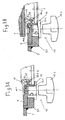
- the hatch viewing devices are arranged, of which the viewing devices 8 located outside the displacement track of the hatch cover 1 and each as a Unit are constructed. Other viewing devices are in the displacement path of the Hatch covers 1. These viewing devices are divided into vehicle-fixed lower parts 7b and in the hatch 1 built-in and displaceable with this upper parts 7a. In the Closed position of the hatch cover 1, the upper parts 7a and the lower parts 7b of Viewing devices aligned with each other and arranged in optical contact. At the edge 6 a of the hatch opening 6, a sealing device is arranged, which in Fig. 1 not shown in Fig. 2 only indicated and in the following with reference to FIG. 3A, 3B and 4A, 4B is explained in more detail.
- the sealing device has a arranged in the edge region of the hatch opening 6 flat outer ring 9, which in one connected with the armor 3 by welding Pick ring 9.1 rests.
- On the inner edge of the outer ring 9 is a substantially cylindrical inner ring 10 is guided in a direction S2 perpendicular to Closing plane of the hatch opening 6 is displaceable.
- On the inner ring 10 is a sealing ring 11 arranged such that its upper edge both in the raised and in the lowered position above the inner ring 10 and the outer ring 9 is located.
- the Sealing ring 11 is attached to a arranged on the inside of the inner ring fixing strip 10.1 vulcanized.
- On its outer side the sealing ring has 11th an outwardly extending annular sealing lobe 11.1, the upper edge the inner ring 10 and the parting line between inner ring 10 and outer ring. 9 overlapping vulcanized to the outer ring 9.
- the lifting and lowering of the inner ring 10 is done with a displacement device, which is designed in the manner of a quick release with a below the Inner ring 10 arranged rotatable plate 12.1, facing the inner ring 10 at its Upper side has a wedge-shaped rising in the circumferential direction surface.
- the actuation takes place via a rotary knob 12.2.
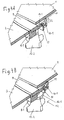
- FIGS. 3A and 3B and 4A and 4B The operation of the sealing device is shown in FIGS. 3A and 3B and 4A and 4B readable.
- the sealing device is in the opened state the hatch, while shown in Figs. 3B and 4B in the closed state is.
- the hatch 1 as shown in Fig. 3B and 4 B, in the closed position is moved, in which he lies above the hatch opening 6 is by rotating the knobs 12.2 distributed on the circumference of the hatch opening 6
- Displacement devices 12 of the inner ring 10 is raised until the sealing ring 11 to the underside of the hatch cover 1 sealingly applies.
- the displacement movement the inner ring 10 can be achieved by a rotation of the knobs 12.2, which is smaller than 360 °.
Abstract
Description
Die Erfindung betrifft eine Ein-Ausstiegsluke für ein Kampffahrzeug, insbesondere
einen Kampfpanzer mit den Merkmalen aus dem Oberbegriff des Patentanspruchs 1.The invention relates to an entry-exit hatch for a combat vehicle, in particular
a battle tank with the features of the preamble of
Eine derartige Ein-Ausstiegsluke ist in DE 33 05 882 C2 beschrieben. Diese bekannte Ein-Ausstiegsluke besitzt eine Dichtungseinrichtung mit einem in der Lukenöffnung angeordneten zylindrischen Ring, der an seiner äußeren Mantelfläche ein Außengewinde aufweist, welches in ein in der Lukenöffnung angeordnetes Innengewinde eingreift. Mit Hilfe von am unteren Ende des Ringes angeordneten Handgriffen kann dieser aufwärts und abwärts geschraubt und damit angehoben oder abgesenkt werden. In der angehobenen Stellung legt sich der obere Rand des zylindrischen Rings dichtend an die Unterseite des Lukendeckels an. Such an entry-hatch is described in DE 33 05 882 C2. This known An exit hatch has a sealing means with one in the hatch opening arranged cylindrical ring, on its outer lateral surface an external thread has, which engages in a arranged in the hatch opening internal thread. With the help of arranged at the bottom of the ring handles this can upwards and screwed down and raised or lowered. In the raised Position sets the upper edge of the cylindrical ring sealingly against the Underside of the hatch cover on.
Bei dieser bekannten Ein- und Ausstiegsluke ist die Bedienung der Dichtungsvorrichtung von innen relativ mühsam und eine einwandfreie Dichtung der Luke, die im geschlossenen Zustand wasser- und ABC-dicht sein soll, schwer zu erreichen.In this known entry and exit hatch is the operation of the sealing device relatively cumbersome from the inside and a proper seal of the hatch in the closed Condition should be water and ABC-tight, difficult to reach.
Der Erfindung liegt die Aufgabe zugrunde, eine Ein-Ausstiegsluke mit den im Oberbegriff
des Patentanspruchs 1 angegebenen Merkmalen so auszugestalten, dass die
Dichtungsvorrichtung einfach aufgebaut, leicht zu bedienen und außerordentlich wirksam
in der Abdichtung ist.The invention is based on the object, a one-exit hatch with the in the preamble
of the
Die Lösung dieser Aufgabe erfolgt erfindungsgemäß mit den Merkmalen aus dem
kennzeichnenden Teil des Patentanspruchs 1. Vorteilhafte Weiterbildungen der Erfindung
sind in den abhängigen Ansprüchen beschrieben.The solution of this object is achieved according to the invention with the features of
characterizing part of
Der Grundgedanke der Erfindung besteht darin, die Dichtungsvorrichtung im wesentlichen mit drei Bauteilen aufzubauen, nämlich einem im Randbereich der Lukenöffnung fest angeordneten flachen Außenring, einem zylindrischen Innenring, der am Innenrand des Außenrings geführt und senkrecht zur Schließebene der Luke verschiebbar ist, und einem Dichtungsring, der an der Innenseite des Innenrings befestigt ist und mit diesem zusammen aus einer abgesenkten Stellung in eine angehobene Dichtungsstellung anhebbar ist, in welche er sich an die Unterseite des geschlossenen Lukendeckels dichtend anlegt.The basic idea of the invention is essentially the sealing device build with three components, namely one in the edge region of the hatch opening fixed flat outer ring, a cylindrical inner ring, the inner edge out of the outer ring and is displaceable perpendicular to the closing plane of the hatch, and a sealing ring, which is attached to the inside of the inner ring and with this together from a lowered position in a raised sealing position can be raised is, in which he sealing himself to the underside of the closed hatch cover invests.
Zur Erzielung einer besonders guten Abdichtung kann der Dichtungsring an den Innenring anvulkanisiert sein und einen sich von seiner Außenseite nach außen erstreckenden Dichtungslappen aufweisen, welcher die Oberseite des Innenrings sowie die ringförmige Trennfuge zwischen Innenring und Außenring überdeckend an den Außenring anvulkanisiert ist. Die Verschiebungsvorrichtung kann in der Art eines Schnellverschlusses ausgebildet sein mit einer unterhalb des Innenrings angeordneten, manuell drehbaren Platte, die an der dem Innenring zugewandten Oberseite eine in Umfangsrichtung keilförmig ansteigende Oberfläche besitzt. Mit dieser Verschiebungsvorrichtung kann mit wenigen Handgriffen und einer Drehung von weniger als 360° der Innenring und damit der Dichtungsring in die gewünschte Dichtungsstellung angehoben werden. Damit ist die Bedienung der Dichtungseinrichtung erheblich vereinfacht.To achieve a particularly good seal of the sealing ring to the inner ring vulcanized and extending from its outside to the outside Have sealing flap, which is the top of the inner ring and the annular Parting joint between inner ring and outer ring overlapping vulcanized to the outer ring is. The displacement device may be in the manner of a quick release be formed with a arranged below the inner ring, manually rotatable Plate, on the inner ring facing the top one in the circumferential direction has wedge-shaped rising surface. With this displacement device can with a few simple steps and a rotation of less than 360 ° the inner ring and so that the sealing ring are raised to the desired sealing position. In order to the operation of the sealing device is considerably simplified.
Im folgenden wird anhand der beigefügten Zeichnungen ein Ausführungsbeispiel für eine Ein-Ausstiegsluke nach der Erfindung näher erläutert.In the following, an exemplary embodiment of the attached drawings an entry-exit hatch according to the invention explained in more detail.
In den Zeichnungen zeigen:
- Fig. 1
- eine Aufsicht auf eine mit einem Lukendeckel verschließbare Ein- und Ausstiegsluke eines Kampffahrzeugs;
- Fig. 2
- einen Schnitt nach der Linie II-II im geöffneten Zustand der Luke;
- Fig. 3A und 3B
- einen gegenüber Fig. 2 stärker vergrößerten vertikalen Teilschnitt durch den Randbereich der Lukenöffnung der Luke nach Fig. 1 und 2 jeweils im geöffneten und geschlossenen Zustand der Luke;
- Fig. 4A und 4B
- die in den Fig. 3A und 3B dargestellten Teile in isometrischer Darstellung.
- Fig. 1
- a view of a lockable with a hatch cover entry and exit hatch of a combat vehicle;
- Fig. 2
- a section along the line II-II in the open state of the hatch;
- FIGS. 3A and 3B
- 2 shows a larger vertical section through the edge region of the hatch opening of the hatch according to FIGS. 1 and 2, in each case in the opened and closed state of the hatch;
- FIGS. 4A and 4B
- the parts shown in Figs. 3A and 3B in isometric view.
In den Fig. 1 und 2 ist die Ein- und Ausstiegsluke eines Kampffahrzeugs, beispielsweise eines Kampfpanzers dargestellt. Die Luke kann sich an der Oberseite der Fahrzeugwanne oder am Turm befinden.In Figs. 1 and 2, the entry and exit hatch of a combat vehicle, for example a battle tank shown. The hatch can be at the top of the vehicle pan or at the tower.
Oberhalb der von der Panzerung 3 umgebenen Lukenöffnung 6 ist ein Lukendeckel 1
angeordnet, der parallel zur Schließebene der Lukenöffnung 6 in Pfeilrichtung S1 verschiebbar
ist. Hierzu sind zu beiden Seiten des Lukendeckels 1 Schienen 4 angeordnet,
in denen mit dem Lukendeckel 1 verbundene Laufrollen 5 geführt sind. Die Vorrichtungen
zum Verschieben des Lukendeckels 1 sind nicht eigens dargestellt. Die Verschiebung
kann prinzipiell von Hand oder motorisch erfolgen, und die hierzu notwendigen
Vorrichtungen können am oder im Lukendeckel 1 angeordnet sein. Above the hatch opening 6 surrounded by the
Im Bereich der Luke sind Sichtgeräte angeordnet, von denen sich die Sichtgeräte 8
außerhalb der Verschiebungsbahn des Lukendeckels 1 befinden und jeweils als eine
Einheit aufgebaut sind. Weitere Sichtgeräte befinden sich in der Verschiebungsbahn des
Lukendeckels 1. Diese Sichtgeräte sind aufgeteilt in fahrzeugfeste Unterteile 7b und in
den Lukendeckel 1 eingebaute und mit diesem verschiebbare Oberteile 7a. In der
Schließstellung des Lukendeckels 1 sind die Oberteile 7a und die Unterteile 7b der
Sichtgeräte fluchtend zueinander und in optischem Kontakt angeordnet. Im Randbereich
6a der Lukenöffnung 6 ist eine Dichtungsvorrichtung angeordnet, die in Fig. 1
nicht und in Fig. 2 nur angedeutet dargestellt ist und im folgenden anhand der Fig. 3A,
3B sowie 4A, 4B näher erläutert wird.In the hatch viewing devices are arranged, of which the
Die Dichtungsvorrichtung besitzt einen im Randbereich der Lukenöffnung 6 angeordneten
flachen Außenring 9, der in einem mit der Panzerung 3 durch Schweißung verbundenen
Aufnahmering 9.1 ruht. Am Innenrand des Außenrings 9 ist ein im wesentlichen
zylindrischer Innenring 10 geführt, der in einer Richtung S2 senkrecht zur
Schließebene der Lukenöffnung 6 verschiebbar ist. Am Innenring 10 ist ein Dichtungsring
11 derart angeordnet, dass seine Oberkante sowohl in der angehobenen als auch in
der abgesenkten Stellung oberhalb des Innenrings 10 und des Außenrings 9 liegt. Der
Dichtungsring 11 ist an eine an der Innenseite des Innenrings angeordnete Befestigungsleiste
10.1 anvulkanisiert. An seiner Außenseite besitzt der Dichtungsring 11
einen sich nach außen erstreckenden ringförmigen Dichtungslappen 11.1, der die Oberkante
des Innenrings 10 sowie die Trennfuge zwischen Innenring10 und Außenring 9
überdeckend an den Außenring 9 anvulkanisiert ist.The sealing device has a arranged in the edge region of the hatch opening 6
flat
Das Anheben und Absenken des Innenrings 10 geschieht mit einer Verschiebungsvorrichtung,
die nach Art eines Schnellverschlusses ausgebildet ist mit einer unterhalb des
Innenrings 10 angeordneten drehbaren Platte 12.1, die an ihrer dem Innenring 10 zugewandten
Oberseite eine in Umfangsrichtung keilförmig ansteigende Oberfläche aufweist.
Die Betätigung erfolgt über einen Drehknopf 12.2. The lifting and lowering of the
Die Wirkungsweise der Dichtungsvorrichtung ist aus den Fig. 3A bzw. 3B und 4A bzw.
4B ablesbar. In den Fig. 3A und 4A ist die Dichtungsvorrichtung im geöffneten Zustand
der Luke dargestellt, während sie in den Fig. 3B und 4B im geschlossenen Zustand dargestellt
ist. Wenn der Lukendeckel 1, wie in Fig. 3B und 4 B dargestellt, in die Geschlossenstellung
verschoben ist, in der er oberhalb der Lukenöffnung 6 liegt, wird
durch Drehen an den Drehknöpfen 12.2 der am Umfang der Lukenöffnung 6 verteilten
Verschiebungsvorrichtungen 12 der Innenring 10 angehoben, bis sich der Dichtungsring
11 an die Unterseite des Lukendeckels 1 dichtend anlegt. Die Verschiebungsbewegung
des Innenrings 10 kann dabei durch eine Drehung der Drehknöpfe 12.2 erzielt werden,
die kleiner als 360° ist. Somit ist das Öffnen und Schließen der Dichtungsvorrichtung
rasch und mit wenig Aufwand durchführbar. Im geschlossenen Zustand des Lukendeckels
1 und der Dichtungseinrichtung ist durch das Anliegen des Dichtungsrings 11
an der Unterseite des Lukendeckels 1 und die dichte, durch Anvulkanisieren erzeugte
Verbindung zwischen dem Dichtungsring 11 und dem Innenring 10 sowie dem Dichtungslappen
11.1 und dem Außenring 9 eine sehr gute Abdichtung erreicht.The operation of the sealing device is shown in FIGS. 3A and 3B and 4A and
4B readable. In Figs. 3A and 4A, the sealing device is in the opened state
the hatch, while shown in Figs. 3B and 4B in the closed state
is. When the
Aufgrund der oben erläuterten Verriegelung der Dichtungsvorrichtung mittels der
am Umfang der Lukenöffnung verteilten, durch die Drehknöpfe 12.2 betätigten Verschiebungsvorrichtungen
12 ist es nicht mehr notwendig, die Dichtung kreisförmig
auszubilden. Sie kann auch andere Formen annehmen.Due to the above-explained locking of the sealing device by means of
distributed on the circumference of the hatch opening, actuated by the knobs 12.2
Claims (4)
Priority Applications (1)
| Application Number | Priority Date | Filing Date | Title |
|---|---|---|---|
| PL04024904T PL1528352T3 (en) | 2003-11-03 | 2004-10-20 | Manhole cover for an armoured vehicle, in particular for a tank |
Applications Claiming Priority (2)
| Application Number | Priority Date | Filing Date | Title |
|---|---|---|---|
| DE20316836U | 2003-11-03 | ||
| DE20316836U DE20316836U1 (en) | 2003-11-03 | 2003-11-03 | One-exit hatch for a combat vehicle, in particular a main battle tank |
Publications (2)
| Publication Number | Publication Date |
|---|---|
| EP1528352A1 true EP1528352A1 (en) | 2005-05-04 |
| EP1528352B1 EP1528352B1 (en) | 2006-05-10 |
Family
ID=30470109
Family Applications (1)
| Application Number | Title | Priority Date | Filing Date |
|---|---|---|---|
| EP04024904A Not-in-force EP1528352B1 (en) | 2003-11-03 | 2004-10-20 | Manhole cover for an armoured vehicle, in particular for a tank |
Country Status (7)
| Country | Link |
|---|---|
| EP (1) | EP1528352B1 (en) |
| AT (1) | ATE326002T1 (en) |
| DE (2) | DE20316836U1 (en) |
| DK (1) | DK1528352T3 (en) |
| ES (1) | ES2262080T3 (en) |
| NO (1) | NO20044719L (en) |
| PL (1) | PL1528352T3 (en) |
Families Citing this family (2)
| Publication number | Priority date | Publication date | Assignee | Title |
|---|---|---|---|---|
| DE102004059016B4 (en) | 2004-12-08 | 2007-03-08 | Rheinmetall Landsysteme Gmbh | Device for opening and closing a hatch cover, in particular for an armored vehicle |
| DE202005000199U1 (en) * | 2005-01-07 | 2006-05-24 | Krauss-Maffei Wegmann Gmbh & Co. Kg | Sealing device for an entry-exit hatch on a combat vehicle |
Citations (4)
| Publication number | Priority date | Publication date | Assignee | Title |
|---|---|---|---|---|
| DE3305882A1 (en) * | 1983-02-19 | 1984-08-23 | Wegmann & Co GmbH, 3500 Kassel | Combat vehicle, especially battle tank |
| EP0259009A2 (en) * | 1986-08-02 | 1988-03-09 | Winsford Technology Limited | Autoclave sealing |
| US5408783A (en) * | 1992-11-28 | 1995-04-25 | Firma Wegmann & Co. Gmbh | Device for opening and closing a hatch on a combat vehicle, especially a military tank |
| DE19504922A1 (en) * | 1994-02-17 | 1995-08-24 | Wegmann & Co Gmbh | Entry and exit hatch for armoured fighting vehicle |
-
2003
- 2003-11-03 DE DE20316836U patent/DE20316836U1/en not_active Expired - Lifetime
-
2004
- 2004-10-20 DE DE502004000532T patent/DE502004000532D1/en active Active
- 2004-10-20 AT AT04024904T patent/ATE326002T1/en not_active IP Right Cessation
- 2004-10-20 EP EP04024904A patent/EP1528352B1/en not_active Not-in-force
- 2004-10-20 DK DK04024904T patent/DK1528352T3/en active
- 2004-10-20 ES ES04024904T patent/ES2262080T3/en active Active
- 2004-10-20 PL PL04024904T patent/PL1528352T3/en unknown
- 2004-11-01 NO NO20044719A patent/NO20044719L/en not_active Application Discontinuation
Patent Citations (5)
| Publication number | Priority date | Publication date | Assignee | Title |
|---|---|---|---|---|
| DE3305882A1 (en) * | 1983-02-19 | 1984-08-23 | Wegmann & Co GmbH, 3500 Kassel | Combat vehicle, especially battle tank |
| DE3305882C2 (en) | 1983-02-19 | 1991-09-26 | Wegmann & Co Gmbh, 3500 Kassel, De | |
| EP0259009A2 (en) * | 1986-08-02 | 1988-03-09 | Winsford Technology Limited | Autoclave sealing |
| US5408783A (en) * | 1992-11-28 | 1995-04-25 | Firma Wegmann & Co. Gmbh | Device for opening and closing a hatch on a combat vehicle, especially a military tank |
| DE19504922A1 (en) * | 1994-02-17 | 1995-08-24 | Wegmann & Co Gmbh | Entry and exit hatch for armoured fighting vehicle |
Also Published As
| Publication number | Publication date |
|---|---|
| PL1528352T3 (en) | 2006-08-31 |
| ES2262080T3 (en) | 2006-11-16 |
| EP1528352B1 (en) | 2006-05-10 |
| ATE326002T1 (en) | 2006-06-15 |
| DE20316836U1 (en) | 2004-01-15 |
| DE502004000532D1 (en) | 2006-06-14 |
| NO20044719L (en) | 2005-05-04 |
| DK1528352T3 (en) | 2006-08-28 |
Similar Documents
| Publication | Publication Date | Title |
|---|---|---|
| DE3305882C2 (en) | ||
| DE2840721A1 (en) | COK OVEN DOOR | |
| WO1985002593A1 (en) | Container, particularly for a transport installation | |
| DE1575424A1 (en) | Device for preventing the deposition of dust on the guide rails of a precision apparatus | |
| EP1528352B1 (en) | Manhole cover for an armoured vehicle, in particular for a tank | |
| EP0540848B1 (en) | Rotating ring mount for a light gun on an armoured combat vehicle, especially on the hatch of a tank | |
| DE3022320C2 (en) | ||
| DE2004907A1 (en) | Device for regulating the flow rate of a liquid metal | |
| EP1635024A2 (en) | Swing door for public transport vehicles, in particular buses | |
| DE102004036842A1 (en) | One-exit hatch for a combat vehicle, in particular a main battle tank | |
| DE10315797B4 (en) | Closure mechanism for a container with lid | |
| EP3689786A1 (en) | Waste receiving apparatus | |
| DE4330516A1 (en) | Manhole cover | |
| DE2100568A1 (en) | Closure means made from coupling segments with a U-shaped profile, in particular for diving equipment | |
| DE10337005A1 (en) | Hatch for a combat vehicle, especially a tank, comprises a sealing cover that can be displaced between an open and a closed position independently of a protective cover | |
| DE2802873A1 (en) | CLOSING FLAP FOR GAS DUCTS | |
| DE3237226A1 (en) | Press-on sliding window | |
| DE1750164A1 (en) | Elastic sealing cover | |
| DE10158902C1 (en) | Sealing device for a door comprises a sliding device laterally offset on a side part of the frame, and a counter-pressure device having a stop device with a contact part interacting with the sliding device | |
| DE2355779A1 (en) | Cover for vehicle mounted large vessel - is kept closed by enclosing strap expanded to allow release from vessel mouth | |
| DE202005000199U1 (en) | Sealing device for an entry-exit hatch on a combat vehicle | |
| DE2252861A1 (en) | LOCKING ARRANGEMENT FOR OPENINGS | |
| EP1607299A2 (en) | Locking device for doors on vehicles of the public transit and main-line rail transport | |
| AT360294B (en) | LOCKING DEVICE FOR LID | |
| DE1525978C3 (en) | Removable hinged locking flap |
Legal Events
| Date | Code | Title | Description |
|---|---|---|---|
| PUAI | Public reference made under article 153(3) epc to a published international application that has entered the european phase |
Free format text: ORIGINAL CODE: 0009012 |
|
| AK | Designated contracting states |
Kind code of ref document: A1 Designated state(s): AT BE BG CH CY CZ DE DK EE ES FI FR GB GR HU IE IT LI LU MC NL PL PT RO SE SI SK TR |
|
| AX | Request for extension of the european patent |
Extension state: AL HR LT LV MK |
|
| 17P | Request for examination filed |
Effective date: 20050502 |
|
| GRAP | Despatch of communication of intention to grant a patent |
Free format text: ORIGINAL CODE: EPIDOSNIGR1 |
|
| AKX | Designation fees paid |
Designated state(s): AT BE BG CH CY CZ DE DK EE ES FI FR GB GR HU IE IT LI LU MC NL PL PT RO SE SI SK TR |
|
| GRAS | Grant fee paid |
Free format text: ORIGINAL CODE: EPIDOSNIGR3 |
|
| GRAA | (expected) grant |
Free format text: ORIGINAL CODE: 0009210 |
|
| AK | Designated contracting states |
Kind code of ref document: B1 Designated state(s): AT BE BG CH CY CZ DE DK EE ES FI FR GB GR HU IE IT LI LU MC NL PL PT RO SE SI SK TR |
|
| PG25 | Lapsed in a contracting state [announced via postgrant information from national office to epo] |
Ref country code: IT Free format text: LAPSE BECAUSE OF FAILURE TO SUBMIT A TRANSLATION OF THE DESCRIPTION OR TO PAY THE FEE WITHIN THE PRESCRIBED TIME-LIMIT;WARNING: LAPSES OF ITALIAN PATENTS WITH EFFECTIVE DATE BEFORE 2007 MAY HAVE OCCURRED AT ANY TIME BEFORE 2007. THE CORRECT EFFECTIVE DATE MAY BE DIFFERENT FROM THE ONE RECORDED. Effective date: 20060510 Ref country code: SI Free format text: LAPSE BECAUSE OF FAILURE TO SUBMIT A TRANSLATION OF THE DESCRIPTION OR TO PAY THE FEE WITHIN THE PRESCRIBED TIME-LIMIT Effective date: 20060510 Ref country code: IE Free format text: LAPSE BECAUSE OF FAILURE TO SUBMIT A TRANSLATION OF THE DESCRIPTION OR TO PAY THE FEE WITHIN THE PRESCRIBED TIME-LIMIT Effective date: 20060510 |
|
| REG | Reference to a national code |
Ref country code: GB Ref legal event code: FG4D Free format text: NOT ENGLISH |
|
| REG | Reference to a national code |
Ref country code: CH Ref legal event code: EP |
|
| GBT | Gb: translation of ep patent filed (gb section 77(6)(a)/1977) |
Effective date: 20060510 |
|
| REG | Reference to a national code |
Ref country code: CH Ref legal event code: NV Representative=s name: A. BRAUN, BRAUN, HERITIER, ESCHMANN AG PATENTANWAE |
|
| REF | Corresponds to: |
Ref document number: 502004000532 Country of ref document: DE Date of ref document: 20060614 Kind code of ref document: P |
|
| REG | Reference to a national code |
Ref country code: IE Ref legal event code: FG4D Free format text: LANGUAGE OF EP DOCUMENT: GERMAN |
|
| REG | Reference to a national code |
Ref country code: RO Ref legal event code: EPE |
|
| REG | Reference to a national code |
Ref country code: SE Ref legal event code: TRGR |
|
| REG | Reference to a national code |
Ref country code: DK Ref legal event code: T3 |
|
| REG | Reference to a national code |
Ref country code: GR Ref legal event code: EP Ref document number: 20060402442 Country of ref document: GR |
|
| PG25 | Lapsed in a contracting state [announced via postgrant information from national office to epo] |
Ref country code: PT Free format text: LAPSE BECAUSE OF FAILURE TO SUBMIT A TRANSLATION OF THE DESCRIPTION OR TO PAY THE FEE WITHIN THE PRESCRIBED TIME-LIMIT Effective date: 20061010 |
|
| PGFP | Annual fee paid to national office [announced via postgrant information from national office to epo] |
Ref country code: RO Payment date: 20061013 Year of fee payment: 3 |
|
| PG25 | Lapsed in a contracting state [announced via postgrant information from national office to epo] |
Ref country code: MC Free format text: LAPSE BECAUSE OF NON-PAYMENT OF DUE FEES Effective date: 20061031 |
|
| REG | Reference to a national code |
Ref country code: ES Ref legal event code: FG2A Ref document number: 2262080 Country of ref document: ES Kind code of ref document: T3 |
|
| ET | Fr: translation filed | ||
| REG | Reference to a national code |
Ref country code: IE Ref legal event code: FD4D |
|
| PLBE | No opposition filed within time limit |
Free format text: ORIGINAL CODE: 0009261 |
|
| STAA | Information on the status of an ep patent application or granted ep patent |
Free format text: STATUS: NO OPPOSITION FILED WITHIN TIME LIMIT |
|
| REG | Reference to a national code |
Ref country code: HU Ref legal event code: AG4A Ref document number: E001120 Country of ref document: HU |
|
| 26N | No opposition filed |
Effective date: 20070213 |
|
| PGFP | Annual fee paid to national office [announced via postgrant information from national office to epo] |
Ref country code: CZ Payment date: 20071009 Year of fee payment: 4 Ref country code: DK Payment date: 20071023 Year of fee payment: 4 Ref country code: HU Payment date: 20071012 Year of fee payment: 4 |
|
| PGFP | Annual fee paid to national office [announced via postgrant information from national office to epo] |
Ref country code: FI Payment date: 20071019 Year of fee payment: 4 Ref country code: AT Payment date: 20071024 Year of fee payment: 4 Ref country code: PL Payment date: 20071008 Year of fee payment: 4 Ref country code: SK Payment date: 20071012 Year of fee payment: 4 |
|
| PGFP | Annual fee paid to national office [announced via postgrant information from national office to epo] |
Ref country code: BE Payment date: 20071022 Year of fee payment: 4 |
|
| REG | Reference to a national code |
Ref country code: CH Ref legal event code: PFA Owner name: KRAUSS-MAFFEI WEGMANN GMBH & CO. KG Free format text: KRAUSS-MAFFEI WEGMANN GMBH & CO. KG#AUGUST-BODE-STRASSE 1#34127 KASSEL (DE) -TRANSFER TO- KRAUSS-MAFFEI WEGMANN GMBH & CO. KG#AUGUST-BODE-STRASSE 1#34127 KASSEL (DE) |
|
| PG25 | Lapsed in a contracting state [announced via postgrant information from national office to epo] |
Ref country code: EE Free format text: LAPSE BECAUSE OF FAILURE TO SUBMIT A TRANSLATION OF THE DESCRIPTION OR TO PAY THE FEE WITHIN THE PRESCRIBED TIME-LIMIT Effective date: 20060510 |
|
| PGFP | Annual fee paid to national office [announced via postgrant information from national office to epo] |
Ref country code: TR Payment date: 20071005 Year of fee payment: 4 |
|
| PG25 | Lapsed in a contracting state [announced via postgrant information from national office to epo] |
Ref country code: LU Free format text: LAPSE BECAUSE OF NON-PAYMENT OF DUE FEES Effective date: 20061020 Ref country code: BG Free format text: LAPSE BECAUSE OF NON-PAYMENT OF DUE FEES Effective date: 20070430 |
|
| PG25 | Lapsed in a contracting state [announced via postgrant information from national office to epo] |
Ref country code: RO Free format text: LAPSE BECAUSE OF NON-PAYMENT OF DUE FEES Effective date: 20071020 Ref country code: CY Free format text: LAPSE BECAUSE OF FAILURE TO SUBMIT A TRANSLATION OF THE DESCRIPTION OR TO PAY THE FEE WITHIN THE PRESCRIBED TIME-LIMIT Effective date: 20060510 |
|
| BERE | Be: lapsed |
Owner name: *KRAUSS-MAFFEI WEGMANN G.M.B.H. & CO. K.G. Effective date: 20081031 |
|
| REG | Reference to a national code |
Ref country code: DK Ref legal event code: EBP |
|
| NLV4 | Nl: lapsed or anulled due to non-payment of the annual fee |
Effective date: 20090501 |
|
| PG25 | Lapsed in a contracting state [announced via postgrant information from national office to epo] |
Ref country code: FI Free format text: LAPSE BECAUSE OF NON-PAYMENT OF DUE FEES Effective date: 20081020 Ref country code: NL Free format text: LAPSE BECAUSE OF NON-PAYMENT OF DUE FEES Effective date: 20090501 |
|
| PG25 | Lapsed in a contracting state [announced via postgrant information from national office to epo] |
Ref country code: AT Free format text: LAPSE BECAUSE OF NON-PAYMENT OF DUE FEES Effective date: 20081020 Ref country code: CZ Free format text: LAPSE BECAUSE OF NON-PAYMENT OF DUE FEES Effective date: 20081020 |
|
| PG25 | Lapsed in a contracting state [announced via postgrant information from national office to epo] |
Ref country code: BE Free format text: LAPSE BECAUSE OF NON-PAYMENT OF DUE FEES Effective date: 20081031 Ref country code: SK Free format text: LAPSE BECAUSE OF NON-PAYMENT OF DUE FEES Effective date: 20081020 |
|
| PG25 | Lapsed in a contracting state [announced via postgrant information from national office to epo] |
Ref country code: DK Free format text: LAPSE BECAUSE OF NON-PAYMENT OF DUE FEES Effective date: 20081031 Ref country code: HU Free format text: LAPSE BECAUSE OF NON-PAYMENT OF DUE FEES Effective date: 20081021 |
|
| PG25 | Lapsed in a contracting state [announced via postgrant information from national office to epo] |
Ref country code: GR Free format text: LAPSE BECAUSE OF NON-PAYMENT OF DUE FEES Effective date: 20090505 |
|
| PG25 | Lapsed in a contracting state [announced via postgrant information from national office to epo] |
Ref country code: PL Free format text: LAPSE BECAUSE OF NON-PAYMENT OF DUE FEES Effective date: 20081020 |
|
| REG | Reference to a national code |
Ref country code: PL Ref legal event code: LAPE |
|
| PG25 | Lapsed in a contracting state [announced via postgrant information from national office to epo] |
Ref country code: TR Free format text: LAPSE BECAUSE OF NON-PAYMENT OF DUE FEES Effective date: 20100917 |
|
| PG25 | Lapsed in a contracting state [announced via postgrant information from national office to epo] |
Ref country code: TR Free format text: LAPSE BECAUSE OF NON-PAYMENT OF DUE FEES Effective date: 20081020 |
|
| REG | Reference to a national code |
Ref country code: CH Ref legal event code: PCAR Free format text: NEW ADDRESS: HOLBEINSTRASSE 36-38, 4051 BASEL (CH) |
|
| REG | Reference to a national code |
Ref country code: FR Ref legal event code: PLFP Year of fee payment: 12 |
|
| REG | Reference to a national code |
Ref country code: FR Ref legal event code: PLFP Year of fee payment: 13 |
|
| REG | Reference to a national code |
Ref country code: FR Ref legal event code: PLFP Year of fee payment: 14 |
|
| REG | Reference to a national code |
Ref country code: FR Ref legal event code: PLFP Year of fee payment: 15 |
|
| PGFP | Annual fee paid to national office [announced via postgrant information from national office to epo] |
Ref country code: DE Payment date: 20181031 Year of fee payment: 15 Ref country code: SE Payment date: 20181025 Year of fee payment: 15 |
|
| PGFP | Annual fee paid to national office [announced via postgrant information from national office to epo] |
Ref country code: ES Payment date: 20181122 Year of fee payment: 15 Ref country code: GB Payment date: 20181025 Year of fee payment: 15 Ref country code: IT Payment date: 20181022 Year of fee payment: 15 Ref country code: FR Payment date: 20181023 Year of fee payment: 15 Ref country code: CH Payment date: 20181025 Year of fee payment: 15 |
|
| REG | Reference to a national code |
Ref country code: DE Ref legal event code: R119 Ref document number: 502004000532 Country of ref document: DE |
|
| REG | Reference to a national code |
Ref country code: CH Ref legal event code: PL |
|
| PG25 | Lapsed in a contracting state [announced via postgrant information from national office to epo] |
Ref country code: LI Free format text: LAPSE BECAUSE OF NON-PAYMENT OF DUE FEES Effective date: 20191031 Ref country code: CH Free format text: LAPSE BECAUSE OF NON-PAYMENT OF DUE FEES Effective date: 20191031 Ref country code: DE Free format text: LAPSE BECAUSE OF NON-PAYMENT OF DUE FEES Effective date: 20200501 |
|
| PG25 | Lapsed in a contracting state [announced via postgrant information from national office to epo] |
Ref country code: SE Free format text: LAPSE BECAUSE OF NON-PAYMENT OF DUE FEES Effective date: 20191021 |
|
| GBPC | Gb: european patent ceased through non-payment of renewal fee |
Effective date: 20191020 |
|
| PG25 | Lapsed in a contracting state [announced via postgrant information from national office to epo] |
Ref country code: IT Free format text: LAPSE BECAUSE OF NON-PAYMENT OF DUE FEES Effective date: 20191020 Ref country code: GB Free format text: LAPSE BECAUSE OF NON-PAYMENT OF DUE FEES Effective date: 20191020 Ref country code: FR Free format text: LAPSE BECAUSE OF NON-PAYMENT OF DUE FEES Effective date: 20191031 |
|
| REG | Reference to a national code |
Ref country code: ES Ref legal event code: FD2A Effective date: 20210301 |
|
| PG25 | Lapsed in a contracting state [announced via postgrant information from national office to epo] |
Ref country code: ES Free format text: LAPSE BECAUSE OF NON-PAYMENT OF DUE FEES Effective date: 20191021 |