EP1528186A1 - Plattenelement zum modularen Aufbau von Gehäusen, vorzugsweise von Lüftungs- und Klimaanlagen - Google Patents
Plattenelement zum modularen Aufbau von Gehäusen, vorzugsweise von Lüftungs- und Klimaanlagen Download PDFInfo
- Publication number
- EP1528186A1 EP1528186A1 EP04023654A EP04023654A EP1528186A1 EP 1528186 A1 EP1528186 A1 EP 1528186A1 EP 04023654 A EP04023654 A EP 04023654A EP 04023654 A EP04023654 A EP 04023654A EP 1528186 A1 EP1528186 A1 EP 1528186A1
- Authority
- EP
- European Patent Office
- Prior art keywords
- plate element
- element according
- metal profiles
- insulating material
- plate
- Prior art date
- Legal status (The legal status is an assumption and is not a legal conclusion. Google has not performed a legal analysis and makes no representation as to the accuracy of the status listed.)
- Granted
Links
- 238000010276 construction Methods 0.000 title claims abstract description 12
- 238000004378 air conditioning Methods 0.000 title claims abstract description 7
- 239000002184 metal Substances 0.000 claims abstract description 49
- 239000011810 insulating material Substances 0.000 claims abstract description 27
- 238000009413 insulation Methods 0.000 claims description 9
- 239000004033 plastic Substances 0.000 claims description 9
- 229920003023 plastic Polymers 0.000 claims description 9
- 239000011490 mineral wool Substances 0.000 claims description 5
- 229920005989 resin Polymers 0.000 claims description 5
- 239000011347 resin Substances 0.000 claims description 5
- 239000003063 flame retardant Substances 0.000 claims description 4
- 239000000463 material Substances 0.000 claims description 4
- 238000009423 ventilation Methods 0.000 claims description 4
- 229920002943 EPDM rubber Polymers 0.000 claims description 3
- 229910000831 Steel Inorganic materials 0.000 claims description 3
- 238000005304 joining Methods 0.000 claims description 3
- 239000010959 steel Substances 0.000 claims description 3
- 238000009434 installation Methods 0.000 abstract 1
- 230000002349 favourable effect Effects 0.000 description 3
- 239000004814 polyurethane Substances 0.000 description 3
- 239000007788 liquid Substances 0.000 description 2
- 238000000465 moulding Methods 0.000 description 2
- 229910001369 Brass Inorganic materials 0.000 description 1
- -1 Polypropylene Polymers 0.000 description 1
- 239000004743 Polypropylene Substances 0.000 description 1
- 238000010521 absorption reaction Methods 0.000 description 1
- 230000032683 aging Effects 0.000 description 1
- 239000010951 brass Substances 0.000 description 1
- 238000005266 casting Methods 0.000 description 1
- 239000002131 composite material Substances 0.000 description 1
- 238000007596 consolidation process Methods 0.000 description 1
- 230000008878 coupling Effects 0.000 description 1
- 238000010168 coupling process Methods 0.000 description 1
- 238000005859 coupling reaction Methods 0.000 description 1
- 238000005336 cracking Methods 0.000 description 1
- 238000013016 damping Methods 0.000 description 1
- 229920001971 elastomer Polymers 0.000 description 1
- 239000003365 glass fiber Substances 0.000 description 1
- 230000020169 heat generation Effects 0.000 description 1
- 239000012212 insulator Substances 0.000 description 1
- 238000004519 manufacturing process Methods 0.000 description 1
- 238000000034 method Methods 0.000 description 1
- 229920001155 polypropylene Polymers 0.000 description 1
- 229920005749 polyurethane resin Polymers 0.000 description 1
- 238000000926 separation method Methods 0.000 description 1
- XLYOFNOQVPJJNP-UHFFFAOYSA-N water Substances O XLYOFNOQVPJJNP-UHFFFAOYSA-N 0.000 description 1
- 238000003466 welding Methods 0.000 description 1
Images


Classifications
-
- E—FIXED CONSTRUCTIONS
- E04—BUILDING
- E04C—STRUCTURAL ELEMENTS; BUILDING MATERIALS
- E04C2/00—Building elements of relatively thin form for the construction of parts of buildings, e.g. sheet materials, slabs, or panels
- E04C2/02—Building elements of relatively thin form for the construction of parts of buildings, e.g. sheet materials, slabs, or panels characterised by specified materials
- E04C2/26—Building elements of relatively thin form for the construction of parts of buildings, e.g. sheet materials, slabs, or panels characterised by specified materials composed of materials covered by two or more of groups E04C2/04, E04C2/08, E04C2/10 or of materials covered by one of these groups with a material not specified in one of the groups
- E04C2/284—Building elements of relatively thin form for the construction of parts of buildings, e.g. sheet materials, slabs, or panels characterised by specified materials composed of materials covered by two or more of groups E04C2/04, E04C2/08, E04C2/10 or of materials covered by one of these groups with a material not specified in one of the groups at least one of the materials being insulating
- E04C2/292—Building elements of relatively thin form for the construction of parts of buildings, e.g. sheet materials, slabs, or panels characterised by specified materials composed of materials covered by two or more of groups E04C2/04, E04C2/08, E04C2/10 or of materials covered by one of these groups with a material not specified in one of the groups at least one of the materials being insulating composed of insulating material and sheet metal
-
- E—FIXED CONSTRUCTIONS
- E04—BUILDING
- E04H—BUILDINGS OR LIKE STRUCTURES FOR PARTICULAR PURPOSES; SWIMMING OR SPLASH BATHS OR POOLS; MASTS; FENCING; TENTS OR CANOPIES, IN GENERAL
- E04H5/00—Buildings or groups of buildings for industrial or agricultural purposes
- E04H5/10—Buildings forming part of cooling plants
Definitions
- the present invention relates to a plate element for the modular construction of housings, preferably of ventilation and air conditioning, with two spaced and in Essentially parallel side walls with arranged therebetween Insulation and at a right angle to the side walls around the plate element extending face.
- Object of the present invention is therefore to provide a plate member, which does not have the above disadvantage and the heat released to the outside area reduced.
- the end face in the cross-sectional view has two spaced apart metal profiles, between which insulating material is arranged.
- a preferred embodiment of the invention provides that the insulating material in Is formed substantially cuboid and that the metal profiles to the insulating material embrace its narrow side. This is the largest possible distance between the Metal profiles allows, whereby the heat transfer is additionally reduced. By the Embrace the metal profiles on the narrow side also less material is needed to to minimize the naturally good heat-conducting metal surfaces.
- a special embodiment of the invention provides that the metal profiles the edge of the Surround insulating material with a substantially U-shaped edge. Through this Design form ensures a good grip of the insulating material, which even at large thermal fluctuations fix remains anchored between the metal profiles. It is advantageously provided that the metal profiles at least partially double-walled are executed, whereby an additional stability of the profile end frame is achieved.
- the metal profiles parallel to each other Have sections between which an insulating gap remains.
- the parallel extending sections will have higher strength and better torsional rigidity achieved the profile end frame, the trapped air gap acts as insulator layer and thereby improves the thermal decoupling.
- the metal profiles for receiving a seal grooves exhibit.
- double circumferential seals can be provided in the Channels are inserted, the RLT housing the required degree of tightness in Unterwie in the overpressure area.
- the seal a EPDM gasket is advantageously provided. This rubber seal is characterized i.a. by Flame resistance and largely resists even large temperature fluctuations.
- the metal profiles are each connected to one side wall are.
- an increased strength of the plate element is achieved.
- the metal profiles preferably from the U-shaped edge to the flat surfaces in one piece are formed, these can be easily connected to the side walls, whereby a stable double-walled construction is achieved.
- For connecting the metal profiles with the side walls are conventional mechanical fasteners, preferably Rivet nuts, provided. Of course, other methods, such as e.g. Spot welding, to be applied.
- the side walls with the metal profiles are at least partially rolled, creating additional strength the construction is made possible. By rotting can also be a vertical slippage the side wall with respect to the metal profiles can be prevented.
- a preferred embodiment of the invention provides that the insulating material heat and fire retardant material, preferably PU resin. Drawing polyurethane resin products u.a. with good fire resistance, good phonic absorption and good Resistance to cracking.
- the Insulating material is interspersed with bushings, which is used to connect the plate element with other plate elements are provided in a modular composite. These can For example, be executed as Eing manmuttern with conventional metric thread for the inclusion of corresponding metric screws are provided.
- the insulating material between the side walls fire-retardant and temperature-insulating material preferably mineral wool
- the Insulation with rock wool provides a favorable insulation against heat, cold and noise.
- a standard product is used, which is nonflammable, water resistant and resistant to aging.
- Fig. 1 shows a cross-sectional view of the end face of a plate element 1.
- Die Front side has two spaced metal profiles 2, 2 ', between which Insulating material 3 is arranged. There is no metallic connection between the Metal profiles 2, 2 ', resulting in an undesirable thermal coupling of a sidewall 4 would lead to the parallel opposite side wall 4 '.
- the metal profiles 2, 2 ' surround the substantially cuboid insulating material 3 on its narrow side, wherein the metal profiles 2, 2 'the edge of the insulating material 3 with a substantially U-shaped Embrace the edge.
- the insulating material 3 is for example PU resin, which in the Production in liquid form between the metal profiles 2, 2 'is poured. To one To prevent leakage of the liquid resin, a piping 5 is provided. These Plastic cover is removed after curing of the insulating material 3 again.
- the metal profiles 2, 2 ' are at least partially double-walled, resulting in a improved stability leads.
- the metal profiles 2, 2 ' include an insulating gap 6, 6' which provides an improved gap thermal decoupling causes.
- the metal profiles 2, 2 ' are with each one side wall 4, 4 'connected. Through this connection will be a cheap Strength of the plate element 1 achieved.
- As connecting means are lateral Rivet nuts 9, 9 'used, which give the construction the necessary support.
- a further increase in strength is due to the rotting of the side walls 4, 4 'with the Metal profiles 2, 2 'achieved, wherein the side walls 4, 4' at least partially into the grooves 7, 7 'of the metal profiles 2, 2' intervene.
- jacks 10 are provided, which are the insulating material 3 enforce.
- These sockets 10 are in the casting process of the insulating material. 3 used and serve to accommodate matching screws, for example, from corresponding Eckprofilen 14 screwed from in the end face of the plate elements 1 become.
- the drawn in Fig. 1 socket 10 is only an example of a variety of passing bushings 10 provided at regular intervals on the front page the plate elements 1 are arranged.
- FIG. 2 shows a three-dimensional representation of the section of FIG. 1 shown in FIG Plate element 1.
- the spaced metal profiles 2, 2 ' enclose the narrow side of the Insulating material 3 with a substantially U-shaped edge.
- the metal profiles 2, 2 ' have at least partially mutually parallel sections, between which a insulating gap 6, 6 'remains.
- the metal profiles have channel-shaped sections 7, 7 ', which are provided for receiving all-round seals 8, 8 '.
- insulation 11 between the side walls 4, 4 'rock wool is provided, for example, next to the insulation has good fire and noise-reducing properties.
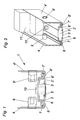
- Fig. 3 shows an RLT housing with plate elements 1 of different standard sizes.
- the plate elements 1 in the Inside is the inclusion of ventilation and air conditioning systems, in addition to strong Heat generation also cause considerable noise emissions.
- the plate elements 1 according to the invention provided, which is characterized by a frameless construction for a substantially distinguish thermally decoupled system.
- the individual plate elements 1 are with the front side connected.
- the plate elements 1 are, for example, with Longitudinal members 12 and transverse bars 13 screwed, at the corners are vertical corner profiles 14th provided, which is also a thermally decoupled system as the plate elements. 1 exhibit.
- the housing may rest, for example, on U-shaped profile rails 15, 15 ', which is mounted vibration-damped by vibration-damping pads.
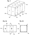
- Fig. 4 shows a schematically illustrated another embodiment of an RLT housing.
- the thermally separated plate elements 1 here have a standardized One size on.
- a corner profile 14th which has a substantially C-shaped section 19 made of metal, preferably made of steel, and a triangular corner strip 17 made of plastic, preferably made of Polypropylene.
- a thermal decoupling can be realized.
- the construction of the doors 16 is also thermally decoupled from the inside to the outside.
- Fig. 4a shows a Front view of the housing shown in Fig. 4.
- Fig. 4b shows a sectional view along the axis A-A of Fig. 4a with a detail C, to which in Fig.6 even closer will be received.
- Fig. 5 shows a schematic front view of a corner profile 14 with the C-shaped Section 19 of metal and the triangular corner molding 17 made of plastic.
- the C-shaped Section 19 is connectable at its central part with the corner strip 17, preferably with the screw 18 shown as an example screwed.
- Fig. 5a shows the corner profile 14 in a perspective view with corner strip 17 and metallic part 19, which are connected by screws 18.
- Fig. 6 shows the detail C of Fig. 4b in an enlarged view.
- the corner profile 14 is provided which has a in Substantially C-shaped section 19 of metal, preferably of steel, and a triangular, corner strip 17 made of plastic.
- a cover strip 20 serves to cover of the C-shaped section.
- the C-shaped portion 19 is at its middle part with the Cornice 17 connectable, for example by the screws 18. It is advantageous that the C-shaped Section 19 of the corner profile 14 of the inner metal profiles 2, 2 'of Plate elements 1, preferably by the corner strip 17, is spaced. This will ensures that no metallic and therefore good heat-conducting connection of inside metal profile 2 to the opposite metal section 2 'and thus to outer side wall 4 'consists.
- a door 16 is shown by way of example, from the Housing interior 21 to the outside is also thermally decoupled.
- This plastic profile 22 arranged with a rectangular cross-section.
- This plastic profile 22 can be glass fiber reinforced. It also serves for thermal decoupling a door seal 24, preferably an EPDM gasket, which provides thermal separation from Interior 21 of the housing causes to the outside.
Landscapes
- Engineering & Computer Science (AREA)
- Architecture (AREA)
- Civil Engineering (AREA)
- Structural Engineering (AREA)
- Building Environments (AREA)
- Thermal Insulation (AREA)
- Cooling Or The Like Of Electrical Apparatus (AREA)
- Air Filters, Heat-Exchange Apparatuses, And Housings Of Air-Conditioning Units (AREA)
- Duct Arrangements (AREA)
Abstract
Description
- Fig. 1
- einen schematischen Querschnitt durch die Stirnfläche eines Ausführungsbeispiels eines Plattenelementes,
- Fig. 2
- eine schematische perspektivische Darstellung eines Ausschnittes des Plattenelementes aus Fig. 1,
- Fig. 3
- ein zusammengebautes Gehäuse mit Plattenelementen verschiedener Standardgrößen,
- Fig. 4, 4a und 4b
- ein weiteres Ausführungsbeispiel eines zusammengebauten Gehäuses sowie verschiedene Ansichten desselben und
- Fig. 5 und 5a
- eine schematische Seitenansicht eines Eckprofils sowie eine perspektivische Darstellung desselben,
- Fig. 6
- eine vergrößerte Darstellung des Details C aus Fig. 4b.
Claims (17)
- Plattenelement zum modularen Aufbau von Gehäusen, vorzugsweise von Lüftungsund Klimaanlagen, mit zwei beabstandeten und im Wesentlichen parallel zueinander verlaufenden Seitenwänden mit dazwischen angeordneter Isolierung und mit einer im rechten Winkel zu den Seitenwänden um das Plattenelement verlaufenden Stirnfläche, dadurch gekennzeichnet, dass die Stirnfläche in der Querschnittansicht zwei voneinander beabstandete Metallprofile (2, 2') aufweist, zwischen denen Isoliermaterial (3) angeordnet ist.
- Plattenelement nach Anspruch 1, dadurch gekennzeichnet, dass das Isoliermaterial (3) im Wesentlichen quaderförmig ausgebildet ist.
- Plattenelement nach Anspruch 1 oder 2, dadurch gekennzeichnet, dass die Metallprofile (2, 2') das Isoliermaterial (3) an dessen Schmalseite umgreifen.
- Plattenelement nach einem der Ansprüche 1 bis 3, dadurch gekennzeichnet, dass die Metallprofile (2, 2') den Rand des Isoliermaterials (3) mit einem im Wesentlichen U-förmigen Rand umgreifen.
- Plattenelement nach einem der Ansprüche 1 bis 4, dadurch gekennzeichnet, dass die Metallprofile (2, 2') zumindest teilweise doppelwandig ausgeführt sind.
- Plattenelement nach einem der Ansprüche 1 bis 5, dadurch gekennzeichnet, dass die Metallprofile (2, 2') parallel zueinander verlaufende Abschnitte aufweisen, zwischen denen ein isolierender Spalt (6) verbleibt.
- Plattenelement nach einem der Ansprüche 1 bis 6, dadurch gekennzeichnet, dass die Metallprofile (2, 2') Rinnen (7, 7') zur Aufnahme einer Dichtung (8) aufweisen.
- Plattenelement nach Anspruch 7, dadurch gekennzeichnet, dass die Dichtung (8) eine EPDM-Dichtung ist.
- Plattenelement nach einem der Ansprüche 1 bis 8, dadurch gekennzeichnet, dass die Metallprofile (2, 2') mit jeweils einer Seitenwand (4, 4') verbunden sind.
- Plattenelement nach Anspruch 9, dadurch gekennzeichnet, dass zum Verbinden der Metallprofile (2, 2') mit den Seitenwänden (4, 4') mechanische Befestigungsmittel (9, 9'), vorzugsweise Einnietmuttern, vorgesehen sind.
- Plattenelement nach Anspruch 9, dadurch gekennzeichnet, dass die Seitenwände (4, 4') mit den Metallprofilen (2, 2') zumindest teilweise verrollt werden.
- Plattenelement nach einem der Ansprüche 1 bis 11, dadurch gekennzeichnet, dass das Isoliermaterial (3) hitze- und feuerhemmendes Material, vorzugsweise PU-Harz, ist.
- Plattenelement nach einem der Ansprüche 1 bis 12, dadurch gekennzeichnet, dass das Isoliermaterial (3) von Buchsen (10) durchsetzt ist.
- Plattenelement nach einem der Ansprüche 1 bis 13, dadurch gekennzeichnet, dass die Isolierung (11) zwischen den Seitenwänden (4, 4') feuerhemmendes und temperaturdämmendes Material, vorzugsweise Mineralwolle, ist.
- Anordnung von mindestens zwei Plattenelementen nach einem der Ansprüche 1 bis 14, dadurch gekennzeichnet, dass zum kantenseitigen Verbinden der Plattenelemente (1) ein Eckprofil (14) vorgesehen ist, welches einen im Wesentlichen C-förmigen Abschnitt (19) aus Metall, vorzugsweise aus Stahl, und eine, vorzugsweise dreieckige, Eckleiste (17) aus Kunststoff aufweist.
- Anordnung nach Anspruch 15, dadurch gekennzeichnet, dass der C-förmige Abschnitt (19) an dessen mittleren Teil mit der Eckleiste (17) verbindbar, vorzugsweise verschraubt, ist.
- Anordnung nach Anspruch 15 oder 16, dadurch gekennzeichnet, dass der C-förmige Abschnitt (19) des Eckprofils (14) von den innenliegenden Metallprofilen (2, 2') der Plattenelemente (1 ) , vorzugsweise durch die Eckleiste (17), beabstandet ist.
Applications Claiming Priority (2)
| Application Number | Priority Date | Filing Date | Title |
|---|---|---|---|
| AT0171403A AT413408B (de) | 2003-10-29 | 2003-10-29 | Plattenelement zum modularen aufbau von gehäuse, vorzugsweise von lüftungs- und klimaanlagen |
| AT17142003 | 2003-10-29 |
Publications (2)
| Publication Number | Publication Date |
|---|---|
| EP1528186A1 true EP1528186A1 (de) | 2005-05-04 |
| EP1528186B1 EP1528186B1 (de) | 2008-05-21 |
Family
ID=34397361
Family Applications (1)
| Application Number | Title | Priority Date | Filing Date |
|---|---|---|---|
| EP04023654A Expired - Lifetime EP1528186B1 (de) | 2003-10-29 | 2004-10-05 | Plattenelement zum modularen Aufbau von Gehäusen, vorzugsweise von Lüftungs- und Klimaanlagen |
Country Status (5)
| Country | Link |
|---|---|
| EP (1) | EP1528186B1 (de) |
| CN (1) | CN100398933C (de) |
| AT (2) | AT413408B (de) |
| DE (1) | DE502004007211D1 (de) |
| TW (1) | TW200523483A (de) |
Families Citing this family (1)
| Publication number | Priority date | Publication date | Assignee | Title |
|---|---|---|---|---|
| CN106766077B (zh) * | 2017-03-21 | 2022-06-07 | 博纳环境设备(太仓)有限公司 | 组合式空调机组框架及其立柱 |
Citations (4)
| Publication number | Priority date | Publication date | Assignee | Title |
|---|---|---|---|---|
| US1697189A (en) * | 1927-06-13 | 1929-01-01 | Kirk & Blum Mfg Company | Heat-insulating structural element |
| DE3042109A1 (de) | 1980-11-07 | 1982-05-27 | Aeolos Holding AG, St.Gallen | Plattenelement zum bau von isolierkammern und -gehaeusen |
| DE3244743A1 (de) * | 1982-12-03 | 1984-06-07 | Karosserie- und Fahrzeugbau Werner Brandt, 4923 Extertal | Rollwand fuer kuehl- und isolierbehaelter |
| FR2604739A1 (fr) * | 1986-10-07 | 1988-04-08 | Cegedur | Panneau isolant |
-
2003
- 2003-10-29 AT AT0171403A patent/AT413408B/de not_active IP Right Cessation
-
2004
- 2004-10-05 AT AT04023654T patent/ATE396314T1/de not_active IP Right Cessation
- 2004-10-05 TW TW093130057A patent/TW200523483A/zh unknown
- 2004-10-05 EP EP04023654A patent/EP1528186B1/de not_active Expired - Lifetime
- 2004-10-05 DE DE502004007211T patent/DE502004007211D1/de not_active Expired - Fee Related
- 2004-10-29 CN CNB2004100901733A patent/CN100398933C/zh not_active Expired - Fee Related
Patent Citations (4)
| Publication number | Priority date | Publication date | Assignee | Title |
|---|---|---|---|---|
| US1697189A (en) * | 1927-06-13 | 1929-01-01 | Kirk & Blum Mfg Company | Heat-insulating structural element |
| DE3042109A1 (de) | 1980-11-07 | 1982-05-27 | Aeolos Holding AG, St.Gallen | Plattenelement zum bau von isolierkammern und -gehaeusen |
| DE3244743A1 (de) * | 1982-12-03 | 1984-06-07 | Karosserie- und Fahrzeugbau Werner Brandt, 4923 Extertal | Rollwand fuer kuehl- und isolierbehaelter |
| FR2604739A1 (fr) * | 1986-10-07 | 1988-04-08 | Cegedur | Panneau isolant |
Also Published As
| Publication number | Publication date |
|---|---|
| CN1619233A (zh) | 2005-05-25 |
| DE502004007211D1 (de) | 2008-07-03 |
| TWI319057B (de) | 2010-01-01 |
| ATE396314T1 (de) | 2008-06-15 |
| TW200523483A (en) | 2005-07-16 |
| EP1528186B1 (de) | 2008-05-21 |
| ATA17142003A (de) | 2005-07-15 |
| CN100398933C (zh) | 2008-07-02 |
| AT413408B (de) | 2006-02-15 |
Similar Documents
| Publication | Publication Date | Title |
|---|---|---|
| EP1369359A1 (de) | Container | |
| DE102010012159A1 (de) | Mehrteiliges Profilrahmensystem für Türen, Tore, Wintergärten und Fenster | |
| EP2228511B1 (de) | Mehrteiliges Schwellenprofil für eine Hebeschiebetür | |
| EP0117308B1 (de) | Durch ein Metallprofil verstärktes Kunststoffhohlprofil und Rahmen | |
| DE2651281C2 (de) | Wandung aus vorgefertigten Platten, insbesondere für Kühlwagen oder Hochbauten | |
| DE202010001301U1 (de) | Wärmegedämmtes Verbundprofil | |
| EP4495366B1 (de) | Verbundkonstruktion für feststehende und bewegbare flächenelemente | |
| DE69013864T2 (de) | Wärmeisolierendes und feuerhemmendes Wandpaneel. | |
| EP2573307A1 (de) | Mehrteiliges Profilrahmensytem für Türen, Tore, Wintergärten und Fenster | |
| AT413408B (de) | Plattenelement zum modularen aufbau von gehäuse, vorzugsweise von lüftungs- und klimaanlagen | |
| DE102008063482A1 (de) | Gehäuse für Lüftungs- und Klimageräte | |
| AT514289B1 (de) | Tür | |
| DE102016114668B3 (de) | Isoliersteg und Brandschutzkonstruktion mit Isoliersteg | |
| EP1152194A1 (de) | Eckverbindung eines Gehäuserahmens von Lüftungs- und Klimageräten | |
| DE202010011872U1 (de) | Eckverbinder zum Verbinden von Rahmenprofilen für Türen oder Fenster | |
| CH624449A5 (en) | Device for connecting a covering frame to a base frame for windows, facades or room partitions | |
| EP3862523A1 (de) | Profil | |
| DE20100618U1 (de) | Rahmenprofil | |
| EP1143215B1 (de) | Wärmeisolierende Doppelwandung | |
| DE202005000564U1 (de) | Profil für Rahmen von Fenstern, Wandelementen oder Türen | |
| EP1681430A2 (de) | Verbundprofiil für Rahmen von Wandelementen, Türen und Fenstern | |
| DE29819674U1 (de) | Innenverkleidung | |
| DE20121414U1 (de) | Schutzgehäuse, insbesondere Instrumentenschutzhaus | |
| DE19933252B4 (de) | Trennwandsystem | |
| WO2008098691A1 (de) | Mehrteilige, in der flächenausdehnung variable revisionsvorrichtung |
Legal Events
| Date | Code | Title | Description |
|---|---|---|---|
| PUAI | Public reference made under article 153(3) epc to a published international application that has entered the european phase |
Free format text: ORIGINAL CODE: 0009012 |
|
| AK | Designated contracting states |
Kind code of ref document: A1 Designated state(s): AT BE BG CH CY CZ DE DK EE ES FI FR GB GR HU IE IT LI LU MC NL PL PT RO SE SI SK TR |
|
| AX | Request for extension of the european patent |
Extension state: AL HR LT LV MK |
|
| 17P | Request for examination filed |
Effective date: 20050811 |
|
| AKX | Designation fees paid |
Designated state(s): AT BE BG CH CY CZ DE DK EE ES FI FR GB GR HU IE IT LI LU MC NL PL PT RO SE SI SK TR |
|
| 17Q | First examination report despatched |
Effective date: 20071122 |
|
| GRAP | Despatch of communication of intention to grant a patent |
Free format text: ORIGINAL CODE: EPIDOSNIGR1 |
|
| GRAS | Grant fee paid |
Free format text: ORIGINAL CODE: EPIDOSNIGR3 |
|
| GRAA | (expected) grant |
Free format text: ORIGINAL CODE: 0009210 |
|
| AK | Designated contracting states |
Kind code of ref document: B1 Designated state(s): AT BE BG CH CY CZ DE DK EE ES FI FR GB GR HU IE IT LI LU MC NL PL PT RO SE SI SK TR |
|
| REG | Reference to a national code |
Ref country code: GB Ref legal event code: FG4D Free format text: NOT ENGLISH |
|
| REG | Reference to a national code |
Ref country code: CH Ref legal event code: EP |
|
| REF | Corresponds to: |
Ref document number: 502004007211 Country of ref document: DE Date of ref document: 20080703 Kind code of ref document: P |
|
| REG | Reference to a national code |
Ref country code: IE Ref legal event code: FG4D Free format text: LANGUAGE OF EP DOCUMENT: GERMAN |
|
| PG25 | Lapsed in a contracting state [announced via postgrant information from national office to epo] |
Ref country code: SI Free format text: LAPSE BECAUSE OF FAILURE TO SUBMIT A TRANSLATION OF THE DESCRIPTION OR TO PAY THE FEE WITHIN THE PRESCRIBED TIME-LIMIT Effective date: 20080521 |
|
| PG25 | Lapsed in a contracting state [announced via postgrant information from national office to epo] |
Ref country code: ES Free format text: LAPSE BECAUSE OF FAILURE TO SUBMIT A TRANSLATION OF THE DESCRIPTION OR TO PAY THE FEE WITHIN THE PRESCRIBED TIME-LIMIT Effective date: 20080901 Ref country code: FI Free format text: LAPSE BECAUSE OF FAILURE TO SUBMIT A TRANSLATION OF THE DESCRIPTION OR TO PAY THE FEE WITHIN THE PRESCRIBED TIME-LIMIT Effective date: 20080521 |
|
| NLV1 | Nl: lapsed or annulled due to failure to fulfill the requirements of art. 29p and 29m of the patents act | ||
| PG25 | Lapsed in a contracting state [announced via postgrant information from national office to epo] |
Ref country code: PL Free format text: LAPSE BECAUSE OF FAILURE TO SUBMIT A TRANSLATION OF THE DESCRIPTION OR TO PAY THE FEE WITHIN THE PRESCRIBED TIME-LIMIT Effective date: 20080521 Ref country code: NL Free format text: LAPSE BECAUSE OF FAILURE TO SUBMIT A TRANSLATION OF THE DESCRIPTION OR TO PAY THE FEE WITHIN THE PRESCRIBED TIME-LIMIT Effective date: 20080521 |
|
| REG | Reference to a national code |
Ref country code: IE Ref legal event code: FD4D |
|
| PG25 | Lapsed in a contracting state [announced via postgrant information from national office to epo] |
Ref country code: IE Free format text: LAPSE BECAUSE OF FAILURE TO SUBMIT A TRANSLATION OF THE DESCRIPTION OR TO PAY THE FEE WITHIN THE PRESCRIBED TIME-LIMIT Effective date: 20080521 Ref country code: CZ Free format text: LAPSE BECAUSE OF FAILURE TO SUBMIT A TRANSLATION OF THE DESCRIPTION OR TO PAY THE FEE WITHIN THE PRESCRIBED TIME-LIMIT Effective date: 20080521 Ref country code: PT Free format text: LAPSE BECAUSE OF FAILURE TO SUBMIT A TRANSLATION OF THE DESCRIPTION OR TO PAY THE FEE WITHIN THE PRESCRIBED TIME-LIMIT Effective date: 20081021 Ref country code: DK Free format text: LAPSE BECAUSE OF FAILURE TO SUBMIT A TRANSLATION OF THE DESCRIPTION OR TO PAY THE FEE WITHIN THE PRESCRIBED TIME-LIMIT Effective date: 20080521 Ref country code: SE Free format text: LAPSE BECAUSE OF FAILURE TO SUBMIT A TRANSLATION OF THE DESCRIPTION OR TO PAY THE FEE WITHIN THE PRESCRIBED TIME-LIMIT Effective date: 20080821 |
|
| PG25 | Lapsed in a contracting state [announced via postgrant information from national office to epo] |
Ref country code: RO Free format text: LAPSE BECAUSE OF FAILURE TO SUBMIT A TRANSLATION OF THE DESCRIPTION OR TO PAY THE FEE WITHIN THE PRESCRIBED TIME-LIMIT Effective date: 20080521 Ref country code: SK Free format text: LAPSE BECAUSE OF FAILURE TO SUBMIT A TRANSLATION OF THE DESCRIPTION OR TO PAY THE FEE WITHIN THE PRESCRIBED TIME-LIMIT Effective date: 20080521 |
|
| PLBE | No opposition filed within time limit |
Free format text: ORIGINAL CODE: 0009261 |
|
| STAA | Information on the status of an ep patent application or granted ep patent |
Free format text: STATUS: NO OPPOSITION FILED WITHIN TIME LIMIT |
|
| 26N | No opposition filed |
Effective date: 20090224 |
|
| BERE | Be: lapsed |
Owner name: EUROCLIMA APPARATEBAU GMBH Effective date: 20081031 |
|
| PG25 | Lapsed in a contracting state [announced via postgrant information from national office to epo] |
Ref country code: BG Free format text: LAPSE BECAUSE OF FAILURE TO SUBMIT A TRANSLATION OF THE DESCRIPTION OR TO PAY THE FEE WITHIN THE PRESCRIBED TIME-LIMIT Effective date: 20080821 Ref country code: EE Free format text: LAPSE BECAUSE OF FAILURE TO SUBMIT A TRANSLATION OF THE DESCRIPTION OR TO PAY THE FEE WITHIN THE PRESCRIBED TIME-LIMIT Effective date: 20080521 |
|
| PG25 | Lapsed in a contracting state [announced via postgrant information from national office to epo] |
Ref country code: MC Free format text: LAPSE BECAUSE OF NON-PAYMENT OF DUE FEES Effective date: 20081031 |
|
| REG | Reference to a national code |
Ref country code: CH Ref legal event code: PL |
|
| GBPC | Gb: european patent ceased through non-payment of renewal fee |
Effective date: 20081005 |
|
| REG | Reference to a national code |
Ref country code: FR Ref legal event code: ST Effective date: 20090630 |
|
| PG25 | Lapsed in a contracting state [announced via postgrant information from national office to epo] |
Ref country code: DE Free format text: LAPSE BECAUSE OF NON-PAYMENT OF DUE FEES Effective date: 20090501 Ref country code: IT Free format text: LAPSE BECAUSE OF FAILURE TO SUBMIT A TRANSLATION OF THE DESCRIPTION OR TO PAY THE FEE WITHIN THE PRESCRIBED TIME-LIMIT Effective date: 20080521 |
|
| PG25 | Lapsed in a contracting state [announced via postgrant information from national office to epo] |
Ref country code: BE Free format text: LAPSE BECAUSE OF NON-PAYMENT OF DUE FEES Effective date: 20081031 |
|
| PG25 | Lapsed in a contracting state [announced via postgrant information from national office to epo] |
Ref country code: LI Free format text: LAPSE BECAUSE OF NON-PAYMENT OF DUE FEES Effective date: 20081031 Ref country code: FR Free format text: LAPSE BECAUSE OF NON-PAYMENT OF DUE FEES Effective date: 20081031 Ref country code: CH Free format text: LAPSE BECAUSE OF NON-PAYMENT OF DUE FEES Effective date: 20081031 |
|
| PG25 | Lapsed in a contracting state [announced via postgrant information from national office to epo] |
Ref country code: GB Free format text: LAPSE BECAUSE OF NON-PAYMENT OF DUE FEES Effective date: 20081005 |
|
| PGFP | Annual fee paid to national office [announced via postgrant information from national office to epo] |
Ref country code: AT Payment date: 20091014 Year of fee payment: 6 |
|
| PG25 | Lapsed in a contracting state [announced via postgrant information from national office to epo] |
Ref country code: LU Free format text: LAPSE BECAUSE OF NON-PAYMENT OF DUE FEES Effective date: 20081005 Ref country code: HU Free format text: LAPSE BECAUSE OF FAILURE TO SUBMIT A TRANSLATION OF THE DESCRIPTION OR TO PAY THE FEE WITHIN THE PRESCRIBED TIME-LIMIT Effective date: 20081122 Ref country code: CY Free format text: LAPSE BECAUSE OF FAILURE TO SUBMIT A TRANSLATION OF THE DESCRIPTION OR TO PAY THE FEE WITHIN THE PRESCRIBED TIME-LIMIT Effective date: 20080521 |
|
| PG25 | Lapsed in a contracting state [announced via postgrant information from national office to epo] |
Ref country code: TR Free format text: LAPSE BECAUSE OF FAILURE TO SUBMIT A TRANSLATION OF THE DESCRIPTION OR TO PAY THE FEE WITHIN THE PRESCRIBED TIME-LIMIT Effective date: 20080521 |
|
| PG25 | Lapsed in a contracting state [announced via postgrant information from national office to epo] |
Ref country code: GR Free format text: LAPSE BECAUSE OF FAILURE TO SUBMIT A TRANSLATION OF THE DESCRIPTION OR TO PAY THE FEE WITHIN THE PRESCRIBED TIME-LIMIT Effective date: 20080822 |
|
| PG25 | Lapsed in a contracting state [announced via postgrant information from national office to epo] |
Ref country code: AT Free format text: LAPSE BECAUSE OF NON-PAYMENT OF DUE FEES Effective date: 20101005 |