EP1528186A1 - Panel for modular housing construction in particular of ventilating and air conditioning plants - Google Patents
Panel for modular housing construction in particular of ventilating and air conditioning plants Download PDFInfo
- Publication number
- EP1528186A1 EP1528186A1 EP04023654A EP04023654A EP1528186A1 EP 1528186 A1 EP1528186 A1 EP 1528186A1 EP 04023654 A EP04023654 A EP 04023654A EP 04023654 A EP04023654 A EP 04023654A EP 1528186 A1 EP1528186 A1 EP 1528186A1
- Authority
- EP
- European Patent Office
- Prior art keywords
- plate element
- element according
- metal profiles
- insulating material
- plate
- Prior art date
- Legal status (The legal status is an assumption and is not a legal conclusion. Google has not performed a legal analysis and makes no representation as to the accuracy of the status listed.)
- Granted
Links
- 238000010276 construction Methods 0.000 title claims abstract description 12
- 238000004378 air conditioning Methods 0.000 title claims abstract description 7
- 239000002184 metal Substances 0.000 claims abstract description 49
- 239000011810 insulating material Substances 0.000 claims abstract description 27
- 238000009413 insulation Methods 0.000 claims description 9
- 239000004033 plastic Substances 0.000 claims description 9
- 229920003023 plastic Polymers 0.000 claims description 9
- 239000011490 mineral wool Substances 0.000 claims description 5
- 229920005989 resin Polymers 0.000 claims description 5
- 239000011347 resin Substances 0.000 claims description 5
- 239000003063 flame retardant Substances 0.000 claims description 4
- 239000000463 material Substances 0.000 claims description 4
- 238000009423 ventilation Methods 0.000 claims description 4
- 229920002943 EPDM rubber Polymers 0.000 claims description 3
- 229910000831 Steel Inorganic materials 0.000 claims description 3
- 238000005304 joining Methods 0.000 claims description 3
- 239000010959 steel Substances 0.000 claims description 3
- 238000009434 installation Methods 0.000 abstract 1
- 230000002349 favourable effect Effects 0.000 description 3
- 239000004814 polyurethane Substances 0.000 description 3
- 239000007788 liquid Substances 0.000 description 2
- 238000000465 moulding Methods 0.000 description 2
- 229910001369 Brass Inorganic materials 0.000 description 1
- -1 Polypropylene Polymers 0.000 description 1
- 239000004743 Polypropylene Substances 0.000 description 1
- 238000010521 absorption reaction Methods 0.000 description 1
- 230000032683 aging Effects 0.000 description 1
- 239000010951 brass Substances 0.000 description 1
- 238000005266 casting Methods 0.000 description 1
- 239000002131 composite material Substances 0.000 description 1
- 238000007596 consolidation process Methods 0.000 description 1
- 230000008878 coupling Effects 0.000 description 1
- 238000010168 coupling process Methods 0.000 description 1
- 238000005859 coupling reaction Methods 0.000 description 1
- 238000005336 cracking Methods 0.000 description 1
- 238000013016 damping Methods 0.000 description 1
- 229920001971 elastomer Polymers 0.000 description 1
- 239000003365 glass fiber Substances 0.000 description 1
- 230000020169 heat generation Effects 0.000 description 1
- 239000012212 insulator Substances 0.000 description 1
- 238000004519 manufacturing process Methods 0.000 description 1
- 238000000034 method Methods 0.000 description 1
- 229920001155 polypropylene Polymers 0.000 description 1
- 229920005749 polyurethane resin Polymers 0.000 description 1
- 238000000926 separation method Methods 0.000 description 1
- XLYOFNOQVPJJNP-UHFFFAOYSA-N water Substances O XLYOFNOQVPJJNP-UHFFFAOYSA-N 0.000 description 1
- 238000003466 welding Methods 0.000 description 1
Images


Classifications
-
- E—FIXED CONSTRUCTIONS
- E04—BUILDING
- E04C—STRUCTURAL ELEMENTS; BUILDING MATERIALS
- E04C2/00—Building elements of relatively thin form for the construction of parts of buildings, e.g. sheet materials, slabs, or panels
- E04C2/02—Building elements of relatively thin form for the construction of parts of buildings, e.g. sheet materials, slabs, or panels characterised by specified materials
- E04C2/26—Building elements of relatively thin form for the construction of parts of buildings, e.g. sheet materials, slabs, or panels characterised by specified materials composed of materials covered by two or more of groups E04C2/04, E04C2/08, E04C2/10 or of materials covered by one of these groups with a material not specified in one of the groups
- E04C2/284—Building elements of relatively thin form for the construction of parts of buildings, e.g. sheet materials, slabs, or panels characterised by specified materials composed of materials covered by two or more of groups E04C2/04, E04C2/08, E04C2/10 or of materials covered by one of these groups with a material not specified in one of the groups at least one of the materials being insulating
- E04C2/292—Building elements of relatively thin form for the construction of parts of buildings, e.g. sheet materials, slabs, or panels characterised by specified materials composed of materials covered by two or more of groups E04C2/04, E04C2/08, E04C2/10 or of materials covered by one of these groups with a material not specified in one of the groups at least one of the materials being insulating composed of insulating material and sheet metal
-
- E—FIXED CONSTRUCTIONS
- E04—BUILDING
- E04H—BUILDINGS OR LIKE STRUCTURES FOR PARTICULAR PURPOSES; SWIMMING OR SPLASH BATHS OR POOLS; MASTS; FENCING; TENTS OR CANOPIES, IN GENERAL
- E04H5/00—Buildings or groups of buildings for industrial or agricultural purposes
- E04H5/10—Buildings forming part of cooling plants
Definitions
- the present invention relates to a plate element for the modular construction of housings, preferably of ventilation and air conditioning, with two spaced and in Essentially parallel side walls with arranged therebetween Insulation and at a right angle to the side walls around the plate element extending face.
- Object of the present invention is therefore to provide a plate member, which does not have the above disadvantage and the heat released to the outside area reduced.
- the end face in the cross-sectional view has two spaced apart metal profiles, between which insulating material is arranged.
- a preferred embodiment of the invention provides that the insulating material in Is formed substantially cuboid and that the metal profiles to the insulating material embrace its narrow side. This is the largest possible distance between the Metal profiles allows, whereby the heat transfer is additionally reduced. By the Embrace the metal profiles on the narrow side also less material is needed to to minimize the naturally good heat-conducting metal surfaces.
- a special embodiment of the invention provides that the metal profiles the edge of the Surround insulating material with a substantially U-shaped edge. Through this Design form ensures a good grip of the insulating material, which even at large thermal fluctuations fix remains anchored between the metal profiles. It is advantageously provided that the metal profiles at least partially double-walled are executed, whereby an additional stability of the profile end frame is achieved.
- the metal profiles parallel to each other Have sections between which an insulating gap remains.
- the parallel extending sections will have higher strength and better torsional rigidity achieved the profile end frame, the trapped air gap acts as insulator layer and thereby improves the thermal decoupling.
- the metal profiles for receiving a seal grooves exhibit.
- double circumferential seals can be provided in the Channels are inserted, the RLT housing the required degree of tightness in Unterwie in the overpressure area.
- the seal a EPDM gasket is advantageously provided. This rubber seal is characterized i.a. by Flame resistance and largely resists even large temperature fluctuations.
- the metal profiles are each connected to one side wall are.
- an increased strength of the plate element is achieved.
- the metal profiles preferably from the U-shaped edge to the flat surfaces in one piece are formed, these can be easily connected to the side walls, whereby a stable double-walled construction is achieved.
- For connecting the metal profiles with the side walls are conventional mechanical fasteners, preferably Rivet nuts, provided. Of course, other methods, such as e.g. Spot welding, to be applied.
- the side walls with the metal profiles are at least partially rolled, creating additional strength the construction is made possible. By rotting can also be a vertical slippage the side wall with respect to the metal profiles can be prevented.
- a preferred embodiment of the invention provides that the insulating material heat and fire retardant material, preferably PU resin. Drawing polyurethane resin products u.a. with good fire resistance, good phonic absorption and good Resistance to cracking.
- the Insulating material is interspersed with bushings, which is used to connect the plate element with other plate elements are provided in a modular composite. These can For example, be executed as Eing manmuttern with conventional metric thread for the inclusion of corresponding metric screws are provided.
- the insulating material between the side walls fire-retardant and temperature-insulating material preferably mineral wool
- the Insulation with rock wool provides a favorable insulation against heat, cold and noise.
- a standard product is used, which is nonflammable, water resistant and resistant to aging.
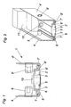
- Fig. 1 shows a cross-sectional view of the end face of a plate element 1.
- Die Front side has two spaced metal profiles 2, 2 ', between which Insulating material 3 is arranged. There is no metallic connection between the Metal profiles 2, 2 ', resulting in an undesirable thermal coupling of a sidewall 4 would lead to the parallel opposite side wall 4 '.
- the metal profiles 2, 2 ' surround the substantially cuboid insulating material 3 on its narrow side, wherein the metal profiles 2, 2 'the edge of the insulating material 3 with a substantially U-shaped Embrace the edge.
- the insulating material 3 is for example PU resin, which in the Production in liquid form between the metal profiles 2, 2 'is poured. To one To prevent leakage of the liquid resin, a piping 5 is provided. These Plastic cover is removed after curing of the insulating material 3 again.
- the metal profiles 2, 2 ' are at least partially double-walled, resulting in a improved stability leads.
- the metal profiles 2, 2 ' include an insulating gap 6, 6' which provides an improved gap thermal decoupling causes.
- the metal profiles 2, 2 ' are with each one side wall 4, 4 'connected. Through this connection will be a cheap Strength of the plate element 1 achieved.
- As connecting means are lateral Rivet nuts 9, 9 'used, which give the construction the necessary support.
- a further increase in strength is due to the rotting of the side walls 4, 4 'with the Metal profiles 2, 2 'achieved, wherein the side walls 4, 4' at least partially into the grooves 7, 7 'of the metal profiles 2, 2' intervene.
- jacks 10 are provided, which are the insulating material 3 enforce.
- These sockets 10 are in the casting process of the insulating material. 3 used and serve to accommodate matching screws, for example, from corresponding Eckprofilen 14 screwed from in the end face of the plate elements 1 become.
- the drawn in Fig. 1 socket 10 is only an example of a variety of passing bushings 10 provided at regular intervals on the front page the plate elements 1 are arranged.
- FIG. 2 shows a three-dimensional representation of the section of FIG. 1 shown in FIG Plate element 1.
- the spaced metal profiles 2, 2 ' enclose the narrow side of the Insulating material 3 with a substantially U-shaped edge.
- the metal profiles 2, 2 ' have at least partially mutually parallel sections, between which a insulating gap 6, 6 'remains.
- the metal profiles have channel-shaped sections 7, 7 ', which are provided for receiving all-round seals 8, 8 '.
- insulation 11 between the side walls 4, 4 'rock wool is provided, for example, next to the insulation has good fire and noise-reducing properties.
- Fig. 3 shows an RLT housing with plate elements 1 of different standard sizes.
- the plate elements 1 in the Inside is the inclusion of ventilation and air conditioning systems, in addition to strong Heat generation also cause considerable noise emissions.
- the plate elements 1 according to the invention provided, which is characterized by a frameless construction for a substantially distinguish thermally decoupled system.
- the individual plate elements 1 are with the front side connected.
- the plate elements 1 are, for example, with Longitudinal members 12 and transverse bars 13 screwed, at the corners are vertical corner profiles 14th provided, which is also a thermally decoupled system as the plate elements. 1 exhibit.
- the housing may rest, for example, on U-shaped profile rails 15, 15 ', which is mounted vibration-damped by vibration-damping pads.
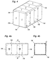
- Fig. 4 shows a schematically illustrated another embodiment of an RLT housing.
- the thermally separated plate elements 1 here have a standardized One size on.
- a corner profile 14th which has a substantially C-shaped section 19 made of metal, preferably made of steel, and a triangular corner strip 17 made of plastic, preferably made of Polypropylene.
- a thermal decoupling can be realized.
- the construction of the doors 16 is also thermally decoupled from the inside to the outside.
- Fig. 4a shows a Front view of the housing shown in Fig. 4.
- Fig. 4b shows a sectional view along the axis A-A of Fig. 4a with a detail C, to which in Fig.6 even closer will be received.
- Fig. 5 shows a schematic front view of a corner profile 14 with the C-shaped Section 19 of metal and the triangular corner molding 17 made of plastic.
- the C-shaped Section 19 is connectable at its central part with the corner strip 17, preferably with the screw 18 shown as an example screwed.
- Fig. 5a shows the corner profile 14 in a perspective view with corner strip 17 and metallic part 19, which are connected by screws 18.
- Fig. 6 shows the detail C of Fig. 4b in an enlarged view.
- the corner profile 14 is provided which has a in Substantially C-shaped section 19 of metal, preferably of steel, and a triangular, corner strip 17 made of plastic.
- a cover strip 20 serves to cover of the C-shaped section.
- the C-shaped portion 19 is at its middle part with the Cornice 17 connectable, for example by the screws 18. It is advantageous that the C-shaped Section 19 of the corner profile 14 of the inner metal profiles 2, 2 'of Plate elements 1, preferably by the corner strip 17, is spaced. This will ensures that no metallic and therefore good heat-conducting connection of inside metal profile 2 to the opposite metal section 2 'and thus to outer side wall 4 'consists.
- a door 16 is shown by way of example, from the Housing interior 21 to the outside is also thermally decoupled.
- This plastic profile 22 arranged with a rectangular cross-section.
- This plastic profile 22 can be glass fiber reinforced. It also serves for thermal decoupling a door seal 24, preferably an EPDM gasket, which provides thermal separation from Interior 21 of the housing causes to the outside.
Landscapes
- Engineering & Computer Science (AREA)
- Architecture (AREA)
- Civil Engineering (AREA)
- Structural Engineering (AREA)
- Building Environments (AREA)
- Thermal Insulation (AREA)
- Air Filters, Heat-Exchange Apparatuses, And Housings Of Air-Conditioning Units (AREA)
- Cooling Or The Like Of Electrical Apparatus (AREA)
- Duct Arrangements (AREA)
Abstract
Description
Die vorliegende Erfindung betrifft ein Plattenelement zum modularen Aufbau von Gehäusen, vorzugsweise von Lüftungs- und Klimaanlagen, mit zwei beabstandeten und im Wesentlichen parallel zueinander verlaufenden Seitenwänden mit dazwischen angeordneter Isolierung und mit einer im rechten Winkel zu den Seitenwänden um das Plattenelement verlaufenden Stirnfläche.The present invention relates to a plate element for the modular construction of housings, preferably of ventilation and air conditioning, with two spaced and in Essentially parallel side walls with arranged therebetween Insulation and at a right angle to the side walls around the plate element extending face.
Der modulare Aufbau mit Plattenelementen im Lüftungs- und Klimaanlagenbau ist bereits bekannt. Der Stand der Technik offenbart zahlreiche Varianten zur Realisierung derartiger Plattenelemente. Die DE 30 42 109 offenbart ein Plattenelement mit einem Isolierstoffkern, an dessen Stirnflächen jeweils ein Stirnprofil von U-förmigem Querschnitt angeordnet ist. Nachteilig bei diesen Plattenelementen ist der hohe Wärmeübergang im Bereich der Stirnprofile.The modular design with panel elements in ventilation and air-conditioning systems is already in place known. The prior art discloses numerous variants for the realization of such Panel members. DE 30 42 109 discloses a plate element with an insulating core, at the end faces in each case an end profile of U-shaped cross-section is arranged. A disadvantage of these plate elements is the high heat transfer in the End profiles.
Aufgabe der vorliegenden Erfindung ist es daher, ein Plattenelement zu schaffen, welches obigen Nachteil nicht aufweist und die an den Außenbereich abgegebene Wärmemenge reduziert.Object of the present invention is therefore to provide a plate member, which does not have the above disadvantage and the heat released to the outside area reduced.
Dies wird erfindungsgemäß dadurch erreicht, dass die Stirnfläche in der Querschnittansicht zwei voneinander beabstandete Metallprofile aufweist, zwischen denen Isoliermaterial angeordnet ist.This is inventively achieved in that the end face in the cross-sectional view has two spaced apart metal profiles, between which insulating material is arranged.
Um den steigenden Anforderungen an Klimageräten gerecht zu werden, müssen technische
Parameter wie Wärmedurchgangskoeffizient oder Wärmebrückenfaktor des Klimagehäuses
entsprechende Werte aufweisen. Die Norm EN 1886 unter Punkt 7 beschreibt eine
Einteilung von RLT (Raumluft-technischen) Geräten in Klassen, wobei die Geräte in den
Klassen T1 bzw. T2 im Wesentlichen vollständig von der warmen zur kalten Seite hin
thermisch entkoppelt sind. Durch die erfindungsgemäße Stirnfläche können diese Normwerte
mit einfacher Konstruktion ermöglicht werden. Durch die beabstandeten Metallprofile kann
eine günstige thermische Entkopplung realisiert werden.In order to meet the increasing demands on air conditioners, technical measures must be taken
Parameters such as heat transfer coefficient or thermal bridge factor of the air conditioning housing
have corresponding values. The standard EN 1886 under
Eine bevorzugte Ausführungsform der Erfindung sieht vor, dass das Isoliermaterial im Wesentlichen quaderförmig ausgebildet ist und dass die Metallprofile das Isoliermaterial an dessen Schmalseite umgreifen. Damit wird ein möglichst großer Abstand zwischen den Metallprofilen ermöglicht, wodurch der Wärmeübergang zusätzlich reduziert wird. Durch das Umgreifen der Metallprofile an der Schmalseite wird zudem weniger Material benötigt, um die naturgemäß gut wärmeleitenden Metallflächen zu minimieren.A preferred embodiment of the invention provides that the insulating material in Is formed substantially cuboid and that the metal profiles to the insulating material embrace its narrow side. This is the largest possible distance between the Metal profiles allows, whereby the heat transfer is additionally reduced. By the Embrace the metal profiles on the narrow side also less material is needed to to minimize the naturally good heat-conducting metal surfaces.
Eine spezielle Ausführungsform der Erfindung sieht vor, dass die Metallprofile den Rand des Isoliermaterials mit einem im Wesentlichen U-förmigen Rand umgreifen. Durch diese Gestaltungsform wird ein guter Halt des Isoliermaterials gewährleistet, welches selbst bei großen thermischen Schwankungen fix zwischen den Metallprofilen verankert bleibt. Vorteilhaft ist vorgesehen, dass die Metallprofile zumindest teilweise doppelwandig ausgeführt sind, wodurch eine zusätzliche Stabilität des Profilstirnrahmens erzielt wird.A special embodiment of the invention provides that the metal profiles the edge of the Surround insulating material with a substantially U-shaped edge. Through this Design form ensures a good grip of the insulating material, which even at large thermal fluctuations fix remains anchored between the metal profiles. It is advantageously provided that the metal profiles at least partially double-walled are executed, whereby an additional stability of the profile end frame is achieved.
Vorteilhaft ist weiters vorgesehen, dass die Metallprofile parallel zueinander verlaufende Abschnitte aufweisen, zwischen denen ein isolierender Spalt verbleibt. Durch die parallel verlaufenden Abschnitte wird eine höhere Festigkeit und eine bessere Verwindungssteifigkeit des Profilstirnrahmens erzielt, der eingeschlossene Luftspalt wirkt als Isolatorschicht und verbessert dadurch die thermische Entkopplung.Advantageously, it is further provided that the metal profiles parallel to each other Have sections between which an insulating gap remains. Through the parallel extending sections will have higher strength and better torsional rigidity achieved the profile end frame, the trapped air gap acts as insulator layer and thereby improves the thermal decoupling.
Günstigerweise ist vorgesehen, dass die Metallprofile zur Aufnahme einer Dichtung Rinnen aufweisen. Vorzugsweise können doppelt umlaufende Dichtungen in die vorgesehenen Rinnen eingelegt werden, die dem RLT-Gehäuse den erforderlichen Dichtheitsgrad im Unterwie im Überdruckbereich verleihen. Vorteilhaft ist vorgesehen, dass die Dichtung eine EPDM-Dichtung ist. Diese Kautschuk-Dichtung zeichnet sich u.a. durch Schwerentflammbarkeit aus und widersteht weitgehend auch großen Temperaturschwankungen.It is advantageously provided that the metal profiles for receiving a seal grooves exhibit. Preferably, double circumferential seals can be provided in the Channels are inserted, the RLT housing the required degree of tightness in Unterwie in the overpressure area. It is advantageously provided that the seal a EPDM gasket is. This rubber seal is characterized i.a. by Flame resistance and largely resists even large temperature fluctuations.
Besonders günstig ist es, wenn die Metallprofile mit jeweils einer Seitenwand verbunden sind. Durch diese Maßnahme wird eine erhöhte Festigkeit des Plattenelementes erreicht. Da die Metallprofile bevorzugt vom U-förmigen Rand bis zu den ebenen Flächen einstückig ausgebildet sind, können diese auf einfache Art mit den Seitenwänden verbunden werden, wobei eine stabile doppelwandige Konstruktion erzielt wird. Zum Verbinden der Metallprofile mit den Seitenwänden werden übliche mechanische Befestigungsmittel, vorzugsweise Einnietmuttern, vorgesehen. Selbstverständlich können auch andere Methoden, wie z.B. Punktschweißen, angewendet werden. Vorteilhaft ist vorgesehen, dass die Seitenwände mit den Metallprofilen zumindest teilweise verrollt werden, wodurch eine zusätzliche Festigkeit der Konstruktion ermöglicht wird. Durch das Verrotten kann auch ein vertikales Verrutschen der Seitenwand in Bezug auf die Metallprofile verhindert werden. It is particularly favorable if the metal profiles are each connected to one side wall are. By this measure, an increased strength of the plate element is achieved. There the metal profiles preferably from the U-shaped edge to the flat surfaces in one piece are formed, these can be easily connected to the side walls, whereby a stable double-walled construction is achieved. For connecting the metal profiles with the side walls are conventional mechanical fasteners, preferably Rivet nuts, provided. Of course, other methods, such as e.g. Spot welding, to be applied. It is advantageously provided that the side walls with the metal profiles are at least partially rolled, creating additional strength the construction is made possible. By rotting can also be a vertical slippage the side wall with respect to the metal profiles can be prevented.
Eine bevorzugte Ausführungsform der Erfindung sieht vor, dass das Isoliermaterial hitze- und feuerhemmendes Material, vorzugsweise PU-Harz, ist. Polyurethanharz-Produkte zeichnen sich u.a. durch gute Feuerbeständigkeit, gute phonische Absorption und gute Widerstandsfähigkeit gegen Rissebildung aus. Vorteilhaft ist vorgesehen, dass das Isoliermaterial von Buchsen durchsetzt ist, die zum Verbinden des Plattenelementes mit anderen Plattenelementen im modularen Verbund vorgesehen sind. Diese können beispielsweise als Eingießmuttern mit üblichem metrischem Gewinde ausgeführt sein, die für die Aufnahme von korrespondierenden metrischen Schrauben vorgesehen sind.A preferred embodiment of the invention provides that the insulating material heat and fire retardant material, preferably PU resin. Drawing polyurethane resin products u.a. with good fire resistance, good phonic absorption and good Resistance to cracking. Advantageously, it is provided that the Insulating material is interspersed with bushings, which is used to connect the plate element with other plate elements are provided in a modular composite. these can For example, be executed as Eingießmuttern with conventional metric thread for the inclusion of corresponding metric screws are provided.
Schließlich ist vorgesehen, dass das Isoliermaterial zwischen den Seitenwänden feuerhemmendes und temperaturdämmendes Material, vorzugsweise Mineralwolle, ist. Die Isolierung mit Steinwolle bewirkt eine günstige Dämmung gegen Hitze, Kälte und Lärm. Darüber hinaus wird ein Standardprodukt verwendet, welches nicht brennbar, wasserabweisend und alterungsbeständig ist.Finally, it is envisaged that the insulating material between the side walls fire-retardant and temperature-insulating material, preferably mineral wool, is. The Insulation with rock wool provides a favorable insulation against heat, cold and noise. In addition, a standard product is used, which is nonflammable, water resistant and resistant to aging.
Weitere Einzelheiten und Vorteile der vorliegenden Erfindung werden anhand der Figurenbeschreibung unter Bezugnahme auf die Zeichnungen im Folgenden näher erläutert. Darin zeigt:
- Fig. 1
- einen schematischen Querschnitt durch die Stirnfläche eines Ausführungsbeispiels eines Plattenelementes,
- Fig. 2
- eine schematische perspektivische Darstellung eines Ausschnittes des Plattenelementes aus Fig. 1,
- Fig. 3
- ein zusammengebautes Gehäuse mit Plattenelementen verschiedener Standardgrößen,
- Fig. 4, 4a und 4b
- ein weiteres Ausführungsbeispiel eines zusammengebauten Gehäuses sowie verschiedene Ansichten desselben und
- Fig. 5 und 5a
- eine schematische Seitenansicht eines Eckprofils sowie eine perspektivische Darstellung desselben,
- Fig. 6
- eine vergrößerte Darstellung des Details C aus Fig. 4b.
- Fig. 1
- a schematic cross-section through the end face of an embodiment of a plate element,
- Fig. 2
- a schematic perspective view of a section of the plate element of Fig. 1,
- Fig. 3
- an assembled housing with plate elements of different standard sizes,
- Fig. 4, 4a and 4b
- a further embodiment of an assembled housing and various views thereof and
- Fig. 5 and 5a
- a schematic side view of a corner profile and a perspective view of the same,
- Fig. 6
- an enlarged view of the detail C of Fig. 4b.
Fig. 1 zeigt eine Querschnittansicht auf die Stirnseite eines Plattenelementes 1. Die
Stirnseite weist zwei voneinander beabstandete Metallprofile 2, 2' auf, zwischen denen
Isoliermaterial 3 angeordnet ist. Es besteht keine metallische Verbindung zwischen den
Metallprofilen 2, 2', die zu einer unerwünschten thermischen Kopplung von einer Seitenwand
4 zur parallel gegenüberliegenden Seitenwand 4' führen würde. Die Metallprofile 2, 2'
umgreifen das im Wesentlichen quaderförmige Isoliermaterial 3 an dessen Schmalseite,
wobei die Metallprofile 2, 2' den Rand des Isoliermaterials 3 mit einem im Wesentlichen U-förmigen
Rand umgreifen. Das Isoliermaterial 3 ist beispielsweise PU-Harz, welches bei der
Herstellung in flüssiger Form zwischen die Metallprofile 2, 2' gegossen wird. Um ein
Auslaufen des flüssigen Harzes zu verhindern, ist ein Keder 5 vorgesehen. Diese
Kunststoffabdeckung wird nach dem Aushärten des Isoliermaterials 3 wieder entfernt.Fig. 1 shows a cross-sectional view of the end face of a
Die Metallprofile 2, 2' sind zumindest teilweise doppelwandig ausgeführt, was zu einer
verbesserten Stabilität führt. Neben diesen parallel zueinander verlaufenden Abschnitten
schließen die Metallprofile 2, 2' einen isolierenden Spalt 6, 6' ein, der eine verbesserte
thermische Entkopplung bewirkt. In weiterer Folge weisen die Metallprofile 2, 2' Rinnen 7, 7'
auf, die zur Aufnahme von Dichtungen 8, 8' vorgesehen sind. Die Metallprofile 2, 2' sind mit
jeweils einer Seitenwand 4, 4' verbunden. Durch diese Verbindung wird eine günstige
Festigkeit des Plattenelementes 1 erzielt. Als Verbindungsmittel werden seitliche
Einnietmuttern 9, 9' verwendet, die der Konstruktion den erforderlichen Halt verleihen. Eine
weitere Festigkeitssteigerung wird durch das Verrotten der Seitenwände 4, 4' mit den
Metallprofilen 2, 2' erreicht, wobei die Seitenwände 4, 4' zumindest teilweise in die Rinnen 7,
7' der Metallprofile 2, 2' eingreifen. Zum Verbinden des Plattenelementes 1 mit den
Stirnflächen anderer Plattenelemente 1 sind Buchsen 10 vorgesehen, die das Isoliermaterial
3 durchsetzen. Diese Buchsen 10 werden beim Gussvorgang des Isoliermaterials 3
eingesetzt und dienen zur Aufnahme passender Schrauben, die beispielsweise von
entsprechenden Eckprofilen 14 aus in die Stirnseite der Plattenelemente 1 eingeschraubt
werden. Die in Fig. 1 eingezeichnete Buchse 10 ist nur beispielhaft für eine Vielzahl von
durchsetzenden Buchsen 10 vorgesehen, die in regelmäßigen Abständen an der Stirnseite
der Plattenelemente 1 angeordnet sind.The metal profiles 2, 2 'are at least partially double-walled, resulting in a
improved stability leads. In addition to these parallel sections
For example, the
Fig. 2 zeigt eine dreidimensionale Darstellung des in Fig. 1 gezeigten Abschnittes eines
Plattenelementes 1. Die beabstandeten Metallprofile 2, 2' umschließen die Schmalseite des
Isoliermaterials 3 mit einem im Wesentlichen U-förmigen Rand. Die Metallprofile 2, 2' weisen
zumindest teilweise parallel zueinander verlaufende Abschnitte auf, zwischen denen ein
isolierender Spalt 6, 6' verbleibt. Die Metallprofile weisen rinnenförmige Abschnitte 7, 7' auf,
die zur Aufnahme von rundum verlaufenden Dichtungen 8, 8' vorgesehen sind. Als Isolierung
11 zwischen den Seitenwänden 4, 4' ist beispielsweise Steinwolle vorgesehen, die neben
der Wärmedämmung gute feuer- und lärmhemmende Eigenschaften aufweist. Durch die
doppelwandige rahmenlose Konstruktion mit den Seitenwänden 4, 4' in Kombination mit dem
Profilstirnrahmen 2, 2' kann eine vorteilhafte Festigung der Konstruktion erreicht werden.
Zusätzliche Stabilität erreicht man durch das Verrotten der Seitenwände 4, 4' mit den
Metallprofilen 2,2'.FIG. 2 shows a three-dimensional representation of the section of FIG. 1 shown in
Fig. 3 zeigt ein RLT-Gehäuse mit Plattenelementen 1 verschiedener Standardgrößen. Im
Inneren ist die Aufnahme von Lüftungs- und Klimaanlagen vorgesehen, die neben starker
Wärmeentwicklung auch beträchtliche Lärmemissionen verursachen. Um eine
entsprechende Isolierwirkung zu erreichen, sind die erfindungsgemäßen Plattenelemente 1
vorgesehen, welche sich durch eine rahmenlose Konstruktion für ein im Wesentlichen
thermisch entkoppeltes System auszeichnen. Die einzelnen Plattenelemente 1 werden mit
der Stirnseite miteinander verbunden. Die Plattenelemente 1 werden beispielsweise mit
Längsholmen 12 und Querholmen 13 verschraubt, an den Ecken sind vertikale Eckprofile 14
vorgesehen, die ebenfalls ein thermisch entkoppeltes System wie die Plattenelemente 1
aufweisen. Das Gehäuse kann beispielsweise auf U-förmigen Profilschienen 15, 15' ruhen,
welches durch schwingungsdämpfende Auflagen vibrationsgedämpft gelagert ist.Fig. 3 shows an RLT housing with
Fig. 4 zeigt ein schematisch dargestelltes weiteres Ausführungsbeispiel eines RLT-Gehäuses.
Die thermisch getrennten Plattenelemente 1 weisen hier eine standardisierte
Einheitsgröße auf. Zum kantenseitigen Verbinden der Plattenelemente 1 ist ein Eckprofil 14
vorgesehen, welches einen im Wesentlichen C-förmigen Abschnitt 19 aus Metall,
vorzugsweise aus Stahl, und eine dreieckige Eckleiste 17 aus Kunststoff, vorzugsweise aus
Polypropylen, aufweist. Durch diese aus Kunststoff bestehende Eckleiste 17 kann kantseitig
ebenfalls eine thermische Entkopplung realisiert werden. Die Konstruktion der Türen 16 ist
ebenfalls von der Innen- zur Außenseite thermisch entkoppelt. Die Fig. 4a zeigt eine
Vorderansicht des in Fig. 4 dargestellten Gehäuses. Die Fig. 4b zeigt eine Schnittdarstellung
entlang der Achse A-A aus Fig. 4a mit einem Detail C, auf welches in der Fig.6 noch näher
eingegangen wird.Fig. 4 shows a schematically illustrated another embodiment of an RLT housing.
The thermally separated
Fig. 5 zeigt eine schematische Vorderansicht eines Eckprofils 14 mit dem C-förmigen
Abschnitt 19 aus Metall sowie der dreieckigen Eckleiste 17 aus Kunststoff. Der C-förmige
Abschnitt 19 ist an seinem mittleren Teil mit der Eckleiste 17 verbindbar, vorzugsweise mit
der beispielhaft gezeigten Schraube 18 verschraubt. Fig. 5 shows a schematic front view of a
Fig. 5a zeigt das Eckprofil 14 in einer perspektivischen Darstellung mit Eckleiste 17 und
metallischem Teil 19, die mit Schrauben 18 verbunden werden.Fig. 5a shows the
Fig. 6 zeigt das Detail C aus Fig. 4b in einer vergrößerten Darstellung. Zum kantseitigen
Verbinden der Plattenelemente 1 ist das Eckprofil 14 vorgesehen, welches einen im
Wesentlichen C-förmigen Abschnitt 19 aus Metall, vorzugsweise aus Stahl, und eine
dreieckige, Eckleiste 17 aus Kunststoff aufweist. Eine Abdeckleiste 20 dient zum Abdecken
des C-förmigen Abschnittes. Der C-förmige Abschnitt 19 ist an seinem mittleren Teil mit der
Eckleiste 17 verbindbar, beispielsweise durch die Schrauben 18. Vorteilhaft ist, dass der C-förmige
Abschnitt 19 des Eckprofils 14 von den innenliegenden Metallprofilen 2, 2' der
Plattenelemente 1, vorzugsweise durch die Eckleiste 17, beabstandet ist. Dadurch wird
sichergestellt, dass keine metallische und damit gut wärmeleitende Verbindung von
innenliegendem Metallprofil 2 zum gegenüberliegenden Metallprofil 2' und damit zur
außenliegenden Seitenwand 4' besteht. Zum kantseitigen Verbinden der Plattenelemente 1
mit dem Eckprofil 14 sind das Isoliermaterial 3 durchsetzende Buchsen 10, beispielsweise
aus Messing, angeordnet, die zur Aufnahme von korrespondierenden Schrauben
vorgesehen sind. Im Weiteren ist in dieser Figur beispielhaft eine Tür 16 dargestellt, die vom
Gehäuseinnenraum 21 nach außen hin ebenfalls thermisch entkoppelt ist. Hierfür ist ein
Kunststoffprofil 22 mit rechteckförmigem Querschnitt angeordnet. Dieses Kunststoffprofil 22
kann beispielsweise glasfaserverstärkt sein. Außerdem dient zur thermischen Entkopplung
eine Türdichtung 24, vorzugsweise eine EPDM-Dichtung, die eine thermische Trennung vom
Innenraum 21 des Gehäuses nach außen hin bewirkt.Fig. 6 shows the detail C of Fig. 4b in an enlarged view. To the Kantide
Connecting the
Es versteht sich von selbst, dass die vorliegende Erfindung nicht auf die in den Figuren dargestellten Ausführungsbeispiele beschränkt ist, noch durch diese eingeschränkt werden soll. Als Isolierung und als Isoliermaterial können selbstverständlich auch andere Materialien als Mineralwolle und PU-Harz eingesetzt werden. Auch die Eckleiste aus Kunststoff kann neben der in den Figuren dargestellten dreieckigen Form eine andere Geometrie, beispielsweise eine polygonale, aufweisen.It goes without saying that the present invention does not apply to those in the figures illustrated embodiments is limited, still be limited by this should. As insulation and as insulating material, of course, other materials be used as mineral wool and PU resin. Also, the plastic corner molding can besides the triangular shape shown in the figures, a different geometry, for example, a polygonal, have.
Claims (17)
Applications Claiming Priority (2)
| Application Number | Priority Date | Filing Date | Title |
|---|---|---|---|
| AT0171403A AT413408B (en) | 2003-10-29 | 2003-10-29 | PANEL ELEMENT FOR MODULAR CONSTRUCTION OF HOUSING, PREFERABLY VENTILATION AND AIR CONDITIONING |
| AT17142003 | 2003-10-29 |
Publications (2)
| Publication Number | Publication Date |
|---|---|
| EP1528186A1 true EP1528186A1 (en) | 2005-05-04 |
| EP1528186B1 EP1528186B1 (en) | 2008-05-21 |
Family
ID=34397361
Family Applications (1)
| Application Number | Title | Priority Date | Filing Date |
|---|---|---|---|
| EP04023654A Expired - Lifetime EP1528186B1 (en) | 2003-10-29 | 2004-10-05 | Panel for modular housing construction in particular of ventilating and air conditioning plants |
Country Status (5)
| Country | Link |
|---|---|
| EP (1) | EP1528186B1 (en) |
| CN (1) | CN100398933C (en) |
| AT (2) | AT413408B (en) |
| DE (1) | DE502004007211D1 (en) |
| TW (1) | TW200523483A (en) |
Families Citing this family (1)
| Publication number | Priority date | Publication date | Assignee | Title |
|---|---|---|---|---|
| CN106766077B (en) * | 2017-03-21 | 2022-06-07 | 博纳环境设备(太仓)有限公司 | Combined air conditioning unit frame and upright post thereof |
Citations (4)
| Publication number | Priority date | Publication date | Assignee | Title |
|---|---|---|---|---|
| US1697189A (en) * | 1927-06-13 | 1929-01-01 | Kirk & Blum Mfg Company | Heat-insulating structural element |
| DE3042109A1 (en) | 1980-11-07 | 1982-05-27 | Aeolos Holding AG, St.Gallen | PANEL ELEMENT FOR THE CONSTRUCTION OF INSULATION CHAMBERS AND HOUSINGS |
| DE3244743A1 (en) * | 1982-12-03 | 1984-06-07 | Karosserie- und Fahrzeugbau Werner Brandt, 4923 Extertal | Roller wall for cooling and insulating containers |
| FR2604739A1 (en) * | 1986-10-07 | 1988-04-08 | Cegedur | Insulating panel |
-
2003
- 2003-10-29 AT AT0171403A patent/AT413408B/en not_active IP Right Cessation
-
2004
- 2004-10-05 DE DE502004007211T patent/DE502004007211D1/en not_active Expired - Fee Related
- 2004-10-05 AT AT04023654T patent/ATE396314T1/en not_active IP Right Cessation
- 2004-10-05 TW TW093130057A patent/TW200523483A/en unknown
- 2004-10-05 EP EP04023654A patent/EP1528186B1/en not_active Expired - Lifetime
- 2004-10-29 CN CNB2004100901733A patent/CN100398933C/en not_active Expired - Fee Related
Patent Citations (4)
| Publication number | Priority date | Publication date | Assignee | Title |
|---|---|---|---|---|
| US1697189A (en) * | 1927-06-13 | 1929-01-01 | Kirk & Blum Mfg Company | Heat-insulating structural element |
| DE3042109A1 (en) | 1980-11-07 | 1982-05-27 | Aeolos Holding AG, St.Gallen | PANEL ELEMENT FOR THE CONSTRUCTION OF INSULATION CHAMBERS AND HOUSINGS |
| DE3244743A1 (en) * | 1982-12-03 | 1984-06-07 | Karosserie- und Fahrzeugbau Werner Brandt, 4923 Extertal | Roller wall for cooling and insulating containers |
| FR2604739A1 (en) * | 1986-10-07 | 1988-04-08 | Cegedur | Insulating panel |
Also Published As
| Publication number | Publication date |
|---|---|
| CN100398933C (en) | 2008-07-02 |
| AT413408B (en) | 2006-02-15 |
| ATA17142003A (en) | 2005-07-15 |
| CN1619233A (en) | 2005-05-25 |
| TWI319057B (en) | 2010-01-01 |
| EP1528186B1 (en) | 2008-05-21 |
| DE502004007211D1 (en) | 2008-07-03 |
| ATE396314T1 (en) | 2008-06-15 |
| TW200523483A (en) | 2005-07-16 |
Similar Documents
| Publication | Publication Date | Title |
|---|---|---|
| EP1369359A1 (en) | Container | |
| DE102010012159A1 (en) | Multipart profile frame system for doors, gates, winter gardens and windows, has outer and inner profiles which are joined to profile frame by snap-joints and insulating bars | |
| EP2228511B1 (en) | Multipart sleeper profile for a lift and slide door | |
| EP0117308B1 (en) | Plastic hollow profile reinforced by a metallic profile and frame | |
| DE2651281C2 (en) | Wall made from prefabricated panels, in particular for refrigerated trucks or high-rise buildings | |
| DE202010001301U1 (en) | Thermally insulated composite profile | |
| EP4495366B1 (en) | Composite structure for stationary and movable surface elements | |
| DE69013864T2 (en) | Heat insulating and fire retardant wall panel. | |
| EP2573307A1 (en) | Multi-section profile frame system for doors, gates, conservatories and windows | |
| AT413408B (en) | PANEL ELEMENT FOR MODULAR CONSTRUCTION OF HOUSING, PREFERABLY VENTILATION AND AIR CONDITIONING | |
| CH650544A5 (en) | PANEL ELEMENT FOR THE CONSTRUCTION OF INSULATION CHAMBERS AND HOUSINGS. | |
| DE102008063482A1 (en) | Housing for ventilation and air conditioning units, has multiple edge profiles and connecting elements interconnected with sandwich panels with metal between two cover plates | |
| AT514289B1 (en) | door | |
| DE102016114668B3 (en) | Insulating bridge and fire protection construction with insulating bar | |
| AT522638B1 (en) | profile | |
| EP1152194A1 (en) | Corner connection for an air conditioning housing frame | |
| EP1004739B1 (en) | Insulating disposition for aluminium section members | |
| DE202010011872U1 (en) | Corner connector for connecting frame profiles for doors or windows | |
| CH624449A5 (en) | Device for connecting a covering frame to a base frame for windows, facades or room partitions | |
| DE20100618U1 (en) | Frame profile | |
| EP1143215B1 (en) | Thermally insulated double wall | |
| DE19654048C2 (en) | Double-walled container with an inner wall and an outer wall made of a thermally highly conductive material, in particular for refrigerators and heating cabinets | |
| DE202005000564U1 (en) | Fixed vertical frame member for door in building has row of square openings one above the other accommodating components including keypad, cylinder lock and pushbutton release | |
| EP1681430A2 (en) | Composite profile for frames of wall elements, doors and windows | |
| DE29819674U1 (en) | interior panelling |
Legal Events
| Date | Code | Title | Description |
|---|---|---|---|
| PUAI | Public reference made under article 153(3) epc to a published international application that has entered the european phase |
Free format text: ORIGINAL CODE: 0009012 |
|
| AK | Designated contracting states |
Kind code of ref document: A1 Designated state(s): AT BE BG CH CY CZ DE DK EE ES FI FR GB GR HU IE IT LI LU MC NL PL PT RO SE SI SK TR |
|
| AX | Request for extension of the european patent |
Extension state: AL HR LT LV MK |
|
| 17P | Request for examination filed |
Effective date: 20050811 |
|
| AKX | Designation fees paid |
Designated state(s): AT BE BG CH CY CZ DE DK EE ES FI FR GB GR HU IE IT LI LU MC NL PL PT RO SE SI SK TR |
|
| 17Q | First examination report despatched |
Effective date: 20071122 |
|
| GRAP | Despatch of communication of intention to grant a patent |
Free format text: ORIGINAL CODE: EPIDOSNIGR1 |
|
| GRAS | Grant fee paid |
Free format text: ORIGINAL CODE: EPIDOSNIGR3 |
|
| GRAA | (expected) grant |
Free format text: ORIGINAL CODE: 0009210 |
|
| AK | Designated contracting states |
Kind code of ref document: B1 Designated state(s): AT BE BG CH CY CZ DE DK EE ES FI FR GB GR HU IE IT LI LU MC NL PL PT RO SE SI SK TR |
|
| REG | Reference to a national code |
Ref country code: GB Ref legal event code: FG4D Free format text: NOT ENGLISH |
|
| REG | Reference to a national code |
Ref country code: CH Ref legal event code: EP |
|
| REF | Corresponds to: |
Ref document number: 502004007211 Country of ref document: DE Date of ref document: 20080703 Kind code of ref document: P |
|
| REG | Reference to a national code |
Ref country code: IE Ref legal event code: FG4D Free format text: LANGUAGE OF EP DOCUMENT: GERMAN |
|
| PG25 | Lapsed in a contracting state [announced via postgrant information from national office to epo] |
Ref country code: SI Free format text: LAPSE BECAUSE OF FAILURE TO SUBMIT A TRANSLATION OF THE DESCRIPTION OR TO PAY THE FEE WITHIN THE PRESCRIBED TIME-LIMIT Effective date: 20080521 |
|
| PG25 | Lapsed in a contracting state [announced via postgrant information from national office to epo] |
Ref country code: ES Free format text: LAPSE BECAUSE OF FAILURE TO SUBMIT A TRANSLATION OF THE DESCRIPTION OR TO PAY THE FEE WITHIN THE PRESCRIBED TIME-LIMIT Effective date: 20080901 Ref country code: FI Free format text: LAPSE BECAUSE OF FAILURE TO SUBMIT A TRANSLATION OF THE DESCRIPTION OR TO PAY THE FEE WITHIN THE PRESCRIBED TIME-LIMIT Effective date: 20080521 |
|
| NLV1 | Nl: lapsed or annulled due to failure to fulfill the requirements of art. 29p and 29m of the patents act | ||
| PG25 | Lapsed in a contracting state [announced via postgrant information from national office to epo] |
Ref country code: PL Free format text: LAPSE BECAUSE OF FAILURE TO SUBMIT A TRANSLATION OF THE DESCRIPTION OR TO PAY THE FEE WITHIN THE PRESCRIBED TIME-LIMIT Effective date: 20080521 Ref country code: NL Free format text: LAPSE BECAUSE OF FAILURE TO SUBMIT A TRANSLATION OF THE DESCRIPTION OR TO PAY THE FEE WITHIN THE PRESCRIBED TIME-LIMIT Effective date: 20080521 |
|
| REG | Reference to a national code |
Ref country code: IE Ref legal event code: FD4D |
|
| PG25 | Lapsed in a contracting state [announced via postgrant information from national office to epo] |
Ref country code: IE Free format text: LAPSE BECAUSE OF FAILURE TO SUBMIT A TRANSLATION OF THE DESCRIPTION OR TO PAY THE FEE WITHIN THE PRESCRIBED TIME-LIMIT Effective date: 20080521 Ref country code: CZ Free format text: LAPSE BECAUSE OF FAILURE TO SUBMIT A TRANSLATION OF THE DESCRIPTION OR TO PAY THE FEE WITHIN THE PRESCRIBED TIME-LIMIT Effective date: 20080521 Ref country code: PT Free format text: LAPSE BECAUSE OF FAILURE TO SUBMIT A TRANSLATION OF THE DESCRIPTION OR TO PAY THE FEE WITHIN THE PRESCRIBED TIME-LIMIT Effective date: 20081021 Ref country code: DK Free format text: LAPSE BECAUSE OF FAILURE TO SUBMIT A TRANSLATION OF THE DESCRIPTION OR TO PAY THE FEE WITHIN THE PRESCRIBED TIME-LIMIT Effective date: 20080521 Ref country code: SE Free format text: LAPSE BECAUSE OF FAILURE TO SUBMIT A TRANSLATION OF THE DESCRIPTION OR TO PAY THE FEE WITHIN THE PRESCRIBED TIME-LIMIT Effective date: 20080821 |
|
| PG25 | Lapsed in a contracting state [announced via postgrant information from national office to epo] |
Ref country code: RO Free format text: LAPSE BECAUSE OF FAILURE TO SUBMIT A TRANSLATION OF THE DESCRIPTION OR TO PAY THE FEE WITHIN THE PRESCRIBED TIME-LIMIT Effective date: 20080521 Ref country code: SK Free format text: LAPSE BECAUSE OF FAILURE TO SUBMIT A TRANSLATION OF THE DESCRIPTION OR TO PAY THE FEE WITHIN THE PRESCRIBED TIME-LIMIT Effective date: 20080521 |
|
| PLBE | No opposition filed within time limit |
Free format text: ORIGINAL CODE: 0009261 |
|
| STAA | Information on the status of an ep patent application or granted ep patent |
Free format text: STATUS: NO OPPOSITION FILED WITHIN TIME LIMIT |
|
| 26N | No opposition filed |
Effective date: 20090224 |
|
| BERE | Be: lapsed |
Owner name: EUROCLIMA APPARATEBAU GMBH Effective date: 20081031 |
|
| PG25 | Lapsed in a contracting state [announced via postgrant information from national office to epo] |
Ref country code: BG Free format text: LAPSE BECAUSE OF FAILURE TO SUBMIT A TRANSLATION OF THE DESCRIPTION OR TO PAY THE FEE WITHIN THE PRESCRIBED TIME-LIMIT Effective date: 20080821 Ref country code: EE Free format text: LAPSE BECAUSE OF FAILURE TO SUBMIT A TRANSLATION OF THE DESCRIPTION OR TO PAY THE FEE WITHIN THE PRESCRIBED TIME-LIMIT Effective date: 20080521 |
|
| PG25 | Lapsed in a contracting state [announced via postgrant information from national office to epo] |
Ref country code: MC Free format text: LAPSE BECAUSE OF NON-PAYMENT OF DUE FEES Effective date: 20081031 |
|
| REG | Reference to a national code |
Ref country code: CH Ref legal event code: PL |
|
| GBPC | Gb: european patent ceased through non-payment of renewal fee |
Effective date: 20081005 |
|
| REG | Reference to a national code |
Ref country code: FR Ref legal event code: ST Effective date: 20090630 |
|
| PG25 | Lapsed in a contracting state [announced via postgrant information from national office to epo] |
Ref country code: DE Free format text: LAPSE BECAUSE OF NON-PAYMENT OF DUE FEES Effective date: 20090501 Ref country code: IT Free format text: LAPSE BECAUSE OF FAILURE TO SUBMIT A TRANSLATION OF THE DESCRIPTION OR TO PAY THE FEE WITHIN THE PRESCRIBED TIME-LIMIT Effective date: 20080521 |
|
| PG25 | Lapsed in a contracting state [announced via postgrant information from national office to epo] |
Ref country code: BE Free format text: LAPSE BECAUSE OF NON-PAYMENT OF DUE FEES Effective date: 20081031 |
|
| PG25 | Lapsed in a contracting state [announced via postgrant information from national office to epo] |
Ref country code: LI Free format text: LAPSE BECAUSE OF NON-PAYMENT OF DUE FEES Effective date: 20081031 Ref country code: FR Free format text: LAPSE BECAUSE OF NON-PAYMENT OF DUE FEES Effective date: 20081031 Ref country code: CH Free format text: LAPSE BECAUSE OF NON-PAYMENT OF DUE FEES Effective date: 20081031 |
|
| PG25 | Lapsed in a contracting state [announced via postgrant information from national office to epo] |
Ref country code: GB Free format text: LAPSE BECAUSE OF NON-PAYMENT OF DUE FEES Effective date: 20081005 |
|
| PGFP | Annual fee paid to national office [announced via postgrant information from national office to epo] |
Ref country code: AT Payment date: 20091014 Year of fee payment: 6 |
|
| PG25 | Lapsed in a contracting state [announced via postgrant information from national office to epo] |
Ref country code: LU Free format text: LAPSE BECAUSE OF NON-PAYMENT OF DUE FEES Effective date: 20081005 Ref country code: HU Free format text: LAPSE BECAUSE OF FAILURE TO SUBMIT A TRANSLATION OF THE DESCRIPTION OR TO PAY THE FEE WITHIN THE PRESCRIBED TIME-LIMIT Effective date: 20081122 Ref country code: CY Free format text: LAPSE BECAUSE OF FAILURE TO SUBMIT A TRANSLATION OF THE DESCRIPTION OR TO PAY THE FEE WITHIN THE PRESCRIBED TIME-LIMIT Effective date: 20080521 |
|
| PG25 | Lapsed in a contracting state [announced via postgrant information from national office to epo] |
Ref country code: TR Free format text: LAPSE BECAUSE OF FAILURE TO SUBMIT A TRANSLATION OF THE DESCRIPTION OR TO PAY THE FEE WITHIN THE PRESCRIBED TIME-LIMIT Effective date: 20080521 |
|
| PG25 | Lapsed in a contracting state [announced via postgrant information from national office to epo] |
Ref country code: GR Free format text: LAPSE BECAUSE OF FAILURE TO SUBMIT A TRANSLATION OF THE DESCRIPTION OR TO PAY THE FEE WITHIN THE PRESCRIBED TIME-LIMIT Effective date: 20080822 |
|
| PG25 | Lapsed in a contracting state [announced via postgrant information from national office to epo] |
Ref country code: AT Free format text: LAPSE BECAUSE OF NON-PAYMENT OF DUE FEES Effective date: 20101005 |