EP1528014A2 - Elément de liaison à verrouillage et libération automatiques - Google Patents
Elément de liaison à verrouillage et libération automatiques Download PDFInfo
- Publication number
- EP1528014A2 EP1528014A2 EP04025556A EP04025556A EP1528014A2 EP 1528014 A2 EP1528014 A2 EP 1528014A2 EP 04025556 A EP04025556 A EP 04025556A EP 04025556 A EP04025556 A EP 04025556A EP 1528014 A2 EP1528014 A2 EP 1528014A2
- Authority
- EP
- European Patent Office
- Prior art keywords
- locking
- connection assembly
- component
- connecting assembly
- assembly according
- Prior art date
- Legal status (The legal status is an assumption and is not a legal conclusion. Google has not performed a legal analysis and makes no representation as to the accuracy of the status listed.)
- Withdrawn
Links
- 230000000903 blocking effect Effects 0.000 claims description 16
- 230000007246 mechanism Effects 0.000 claims description 8
- 238000003780 insertion Methods 0.000 claims description 2
- 230000037431 insertion Effects 0.000 claims description 2
- 230000013011 mating Effects 0.000 claims 1
- 210000003128 head Anatomy 0.000 description 39
- 230000000712 assembly Effects 0.000 description 13
- 238000000429 assembly Methods 0.000 description 13
- 210000001331 nose Anatomy 0.000 description 13
- 238000013461 design Methods 0.000 description 4
- 238000011161 development Methods 0.000 description 3
- 230000018109 developmental process Effects 0.000 description 3
- 210000003746 feather Anatomy 0.000 description 3
- 230000001133 acceleration Effects 0.000 description 2
- 238000013459 approach Methods 0.000 description 2
- 230000008901 benefit Effects 0.000 description 2
- 238000005266 casting Methods 0.000 description 2
- 238000010276 construction Methods 0.000 description 2
- 238000006073 displacement reaction Methods 0.000 description 2
- 238000005096 rolling process Methods 0.000 description 2
- XLYOFNOQVPJJNP-UHFFFAOYSA-N water Substances O XLYOFNOQVPJJNP-UHFFFAOYSA-N 0.000 description 2
- 241000251131 Sphyrna Species 0.000 description 1
- 230000009471 action Effects 0.000 description 1
- 230000015572 biosynthetic process Effects 0.000 description 1
- 230000008859 change Effects 0.000 description 1
- 230000000694 effects Effects 0.000 description 1
- 230000004048 modification Effects 0.000 description 1
- 238000012986 modification Methods 0.000 description 1
- 230000002093 peripheral effect Effects 0.000 description 1
- 230000001681 protective effect Effects 0.000 description 1
- 230000009467 reduction Effects 0.000 description 1
- 238000012549 training Methods 0.000 description 1
- 230000007704 transition Effects 0.000 description 1
Images

Classifications
-
- B—PERFORMING OPERATIONS; TRANSPORTING
- B65—CONVEYING; PACKING; STORING; HANDLING THIN OR FILAMENTARY MATERIAL
- B65D—CONTAINERS FOR STORAGE OR TRANSPORT OF ARTICLES OR MATERIALS, e.g. BAGS, BARRELS, BOTTLES, BOXES, CANS, CARTONS, CRATES, DRUMS, JARS, TANKS, HOPPERS, FORWARDING CONTAINERS; ACCESSORIES, CLOSURES, OR FITTINGS THEREFOR; PACKAGING ELEMENTS; PACKAGES
- B65D90/00—Component parts, details or accessories for large containers
- B65D90/0006—Coupling devices between containers, e.g. ISO-containers
- B65D90/0013—Twist lock
Definitions
- the invention relates to an automatically locking and releasing connection assembly according to the preamble of claim 1.
- WO 01/76980 is an automatically locking and releasing Connecting assembly for connecting corner fittings of sea freight containers known, the above has a rotatable hammer head, which from below with a part of Connecting assembly in a corner fitting of a container is inserted, so that the Connecting assembly after turning the hammer head, the outer wall of the corner fitting between the hammer head and a peripheral flange of the connection assembly receives.
- a protruding sensing lever is formed, the Placing an upper container on a lower container and thereby inserting it a lower part of the connection assembly through the hole of the upper corner fitting the lower container comes into contact with the top of this corner fitting, at further Lowering of the upper container is pivoted against spring force and thereby over a Connecting mechanism locking members from the in the cavity of the corner fitting located bottom part of the connection assembly, which moves the hole of the corner fitting engage behind, so that the corner fittings are interconnected.
- connection assembly a cooperating with the locking mechanism locking device on which a mobility of the locking members back into the lower part of the Interlocking module locks in while the ship is in an inclined position or through rolling and / or pounding movements lateral accelerations on the locking mechanism be exercised.
- the known connection assembly leads to an extraordinary secure mutual attachment or locking stacked one above the other Sea freight containers that are reliable only when the ship is not inclined and not accelerating is released.
- the structure of the connection assembly is relatively complicated.
- connection assembly In a known generic self-locking and releasing connection assembly (fully automatic twist lock, TL-FA from Ships Equipment Center, Bremen)
- the hammer head of the connection assembly is also from below into the slot of a Bottom corner fitting of a container inserted from below, the connection assembly but then rotated a total of about 90 ° and by moving one to a flange of the Shaft area of the connecting assembly provided lever secured.
- the connection assembly is immovably connected in this way with the upper corner fitting.
- the on formed from the upper corner fitting projecting shaft portion of the connection assembly Holding head has a total of four functionally important inclined or guide surfaces.
- a Peculiarity of the known generic connection assembly is that for a mutual Fixing the containers by means of the connection assembly of the upper containers to the lower container must be pivoted, which is not always space. Furthermore there is no positive lock between the containers.
- the invention is based on the object, an automatically locking and releasing connection assembly to connect in particular two sea freight containers, which at Simple construction, the two containers securely locked, with the container when lowering one another or removal from each other need not be mutually pivoted.
- the claim 2 indicates the basic structural design of the invention Joint assembly.
- connection assembly With the features of claim 3 is a torsion-resistant mounting of the connection assembly reached.
- connection assembly is when inserting the holding head in the through hole of the lower component advantageously first pivoted in one direction and / or moved and then pivoted with the features according to claim 4 in the opposite direction and / or shifted, so that the holding surface the through hole of the lower component safely engages behind.
- connection assembly between the attached to each other and preferably in the immediate mutual investment befmdlichen Achieved components, whereby the components are additionally held laterally immovable.
- connection assembly during lowering of the upper component is securely moved to the lower component in its upright position.
- Claims 7 and 8 indicate details of the locking mechanism.
- Claims 9 and 10 are directed to features with which the handling safety the connection assembly is improved.
- the claim 12 indicates an advantageous embodiment of the blocking device.
- the invention is suitable for use wherever one with a through hole trained component to be attached to another component to which the connection assembly is pivotally mounted, wherein the pivoting of the connection assembly according to their insertion through the through hole is blocked.
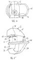
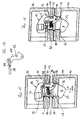
- a connector assembly has a total denoted by 2 Housing containing a shaft portion 4, which at one end in a hammer head. 6 and ends at the other end in a holding head 8.
- the dimensioning of the housing is such that the hammer head 6 can be inserted from below into a slot of a sea freight container is, and after turning by about 90 ° with contact surfaces 10 and 12, an edge of a slot engages, which is formed in a corner fitting of a sea freight container.
- Fig. 1 is smaller than the width of a slot a corner fitting of a sea freight container.
- With respect to the axial direction A are the contact surfaces 10 and 12 offset by a measure d against each other.
- An upper region 14 of the shank region 4 merges via a flange 16 projecting over the shank region with a triangular cross section into a lower region 18 which merges into the holding head 8.
- an axial surface 22 formed on the left side on the region 18 is slightly offset inwards at its projection on the flange opposite the corresponding outer surface of the upper region 14 and ends in accordance with FIG. Fig. 1 below approximately in alignment with the corresponding outer surface of the upper portion, which is parallel to the axial direction AA.
- the at the gem. Fig. 1 formed on the right side of the lower portion 18 surface begins at the flange 16 with respect to the corresponding outer surface of the upper portion outwardly offset and forms a first to the axial direction slightly inclined guide surface 24th
- the holding head 8 has a holding surface extending obliquely outward from the outer surface 22 26, from the outer end of an oppositely beveled guide surface 28 for gem.
- Fig. 1 lower end 30 of the holding head 8 leads. The lower end forms a peak and goes via an inclined surface 32 in the guide surface 24 via.
- a cavity or cavity is located in the interior of the shaft region.
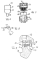
- Fig. 3 shows the housing acc. Fig. 1 and 2 in a view from the left.
- the shaft region is offset relative to the center of the flange 16 and has in its lower region webs 39 which extend obliquely upward from a lower vertex and enter the flange 16 vertically.
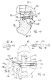
- a feeler lever 42 is mounted in the recess 36 with the aid of a bolt 40 guided through the hole 34 and is biased counterclockwise by a spring 44.
- the feeler lever has a gem.
- Fig. 5 right-hand arm, which ends in a sensing region 46, and an upwardly extending arm 48 which is pivotally connected to a locking member 50, the from a lateral opening 51 (Fig. 2) in the upper end of the shaft portion 4 after is movable out of the left.
- a locking device 52 is arranged, the structure of which is explained with reference to FIGS. 6 and 7.
- the locking device 52 has a housing with an upper part 54 and a lower part 56, in which a plunger 58 is slidably guided.
- the plunger 58 has a shaft 60 and a Head 62 up.
- the top of the head 62 forms a concave surface 64, on which in vertical Position of the plunger 58 a forming a mass body ball 66 automatically in the Center moves.
- the tappet 58 facing inside 68 of the upper part 54 is corresponding to the concave Surface 64 is convex and has a recess 70 in the center. Between the plunger 58 and the upper part, a spring 72 is arranged.
- the distance between the concave surface 64 and the inner surface 68 is approximately equal to that Diameter of the ball 66, so that the ball when on the locking device 52 a lateral acceleration acts, or the locking device is tilted from the vertical, in the space between the concave surface 64 and the inside 68 can move.
- a movement of the plunger 58 is locked upwards.
- the plunger 58 against the force of the spring 72nd are pushed upward, with the ball 66 moves into the recess 70.
- FIG. 8 which shows the feeler lever 42 and the locking member 50, it can be seen that is formed in the locking member 50, a recess 74, in which the front End of the ram 58 can protrude.
- connection assembly The assembly of the described connection assembly is as follows:
- the Spring 44 used in the housing 2, which may be formed in total as a one-piece casting. Subsequently, the assembly of locking member 50 and lever 42 inserted by the bolt 34 is inserted through the hole 34, the lever 42 stores. The locking member 50 is not laterally from the shaft portion. 4 out. In the recess 38, the locking device 52 is inserted and by means of a per se known device, such as a screw cap, snap ring, etc. secured. Preferably a protective cap is attached so that no dirt, water or water from above Similar can penetrate.
- the advantage here is a crowned Training of gem.
- Fig. 1 and 2 right lower inclined surface 102 of the flange 16, through the tilting of the connection assembly 82 in the vertical position is supported.
- the Dimensioning is such that when fully lowered corner fitting 84 (FIG. 11), the contact surface 12 of the hammer head 6 slightly from the inside 90 of the upper corner fitting 76th is removed. As can be seen, engages with fully lowered corner fitting 84, the support surface 26, the slot 96 of the corner fitting 100th
- the thickness of the locking member 50 corresponds approximately to the dimension d (FIG. 1), so that between This and the inside 90 is also a game that is about the game between the Contact surface 12 and the inside 90 corresponds and preferably smaller than d.
- Overall is the extent to which the corner fitting 84 upwardly from the corner fitting 100 when extended Locking pin 50 can be lifted, preferably less than about 12 mm.
- connection assemblies 82 are installed mirror-inverted on the left and right sides, so that because of on one side small distance between the hammer head and the inside of the corner fitting additional security against lateral displacement is given and from the other side for the introduction of the additional lashing Serving components in the lower corner fitting of the upper container plenty of space to Verfi Trent stands.
- the assemblies according to the invention can not only for the mutual, under predetermined Conditions automatically locking and releasing fastening of containers to each other can be used just as well for fixing a container a railway wagon, a truck or any other surface to be used with Is provided receptacles into which the connection assembly similar to the corner fittings 100th gem. Fig. 10 and 11 can be inserted.
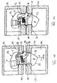
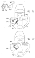
- Figure 17 is a view similar to Figure 9, Figure 15 shows the connection assembly according to FIG. 17 in the view from the left of the section XV-XV in FIG. 14.
- FIGS. 19 to 21 show items of the blocking device.
- the holding head 8 is formed with a transverse bore 110, which according to FIG 19 is stepped in its right end portion and in its left end to a room 112 is extended.
- a bolt 114 is received, at its left end a radially projecting nose 116 is formed, by means of which the bolt 114 in the transverse bore 110 is held non-rotatably and axially movable.
- a control lever 120 is pivotally held by the pins 118 in Engage slots 122 of the operating lever 120.
- a spring 124 is pushed, which is located at the stage of Transverse bore 110 and a screwed onto the bolt 114 nut 126 is supported.
- a bearing opening 128 (FIG. 17) of the sensing lever 42 has a cross-section which corresponds to that of the Bolts 110 in the area of the nose 116 corresponds.
- the operating lever 120 is bent at its left end and ends in a widened Flange 130 (FIG. 21, which shows a view of the operating lever according to FIG. 15 from the left), which flange 130 is formed such that it has a projection 132 of the holding head. 8 can engage.
- the operating lever 120 is in the counterclockwise direction according to FIG pivoted.
- a lower approach 134 reaches the right end of the operating lever 120 in abutment with the edge of the transverse bore 110, so that the bolt 114 against the force of Spring 124 is pulled to the left and moved in his compared to Figure 15 to the left Position can be locked by locking the flange 130 on the projection 132.
- this Position is the nose 116 outside the bearing opening 128 of the feeler lever 42, so that this free is pivotable and the connection assembly functions as a fully automatic assembly, as described above.
- connection assembly locks the two by means the connecting assembly attached to each other corner fittings captive with each other.
- the operating lever 120 is freely accessible in a corner fitting hanging connection assembly and is at two corner fittings interconnecting connection assembly by a slot in the lower corner fitting accessible. Thus, by pressing the operating lever 120 a connection assembly between fully automatic operation (operating lever 120 locked on the projection 132) and blocking operation (operating lever 120 not on the projection 132nd locked).
- the blocking position In the blocking position, a plurality of superimposed containers together of lifted and put into action by crane.
- the blocking position can be adjusted by pivoting of the operating lever 120 are released into the locked release position, so that subsequently the lower container stops.
- the blocking device can be modified in many ways. There can be several Noses 116 may be present ( Figure 19 shows two opposite noses). critical is that the cross section of the bolt 114 is out of round and the cross section of the bearing opening 128th is correspondingly out of round, so that the two non-circular cross-sectional sections mutually engaged can be brought. Furthermore, it is possible to design the blocking device in such a way that that not the pivoting of the feeler lever 42, but directly the displaceability the locking member 50 or the mobility of the plunger 58 of the locking device 52nd is blocked.
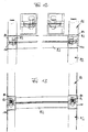
- FIGS. 22 to 25 schematically show a modified embodiment of a blocking device, when in the in Figures 22 and 25 to the left open space of the holding head 8, a lever 140 is mounted.
- the storage of the lever via a slot 142, through which engages an unillustrated, secured in the hammer head pin through.
- the lever 140 is provided with lateral arms 142 for ease of use.
- connection assemblies of the type described can be blocked, not only used in connection assemblies of the type described but in all types of automatic connection assemblies whose automatic function (Self-releasability of two via the connection assembly with each other connected corner fittings in the presence of predetermined conditions) by blocking a Component or moving a component can be locked in a blocking position, for example also connection assemblies, as described in the European patent EP 1 268 311 B1 are described, or even connection assemblies whose automatic function without a movable Part of the connection assembly itself is achieved. Accordingly reserves the Applicant before, the blocking device to the subject of a separate patent application do.
Landscapes
- Engineering & Computer Science (AREA)
- Mechanical Engineering (AREA)
- Load-Engaging Elements For Cranes (AREA)
- Connection Of Plates (AREA)
Applications Claiming Priority (4)
| Application Number | Priority Date | Filing Date | Title |
|---|---|---|---|
| DE2003150087 DE10350087B3 (de) | 2003-10-27 | 2003-10-27 | Selbsttätig sperrende und lösende Verbindungsbaugruppe |
| DE10350087 | 2003-10-27 | ||
| DE200410012838 DE102004012838A1 (de) | 2003-10-27 | 2004-03-16 | Selbsttätig sperrende und lösende Verbindungsbaugruppe |
| DE102004012838 | 2004-03-16 |
Publications (2)
| Publication Number | Publication Date |
|---|---|
| EP1528014A2 true EP1528014A2 (fr) | 2005-05-04 |
| EP1528014A3 EP1528014A3 (fr) | 2005-09-07 |
Family
ID=34424336
Family Applications (1)
| Application Number | Title | Priority Date | Filing Date |
|---|---|---|---|
| EP04025556A Withdrawn EP1528014A3 (fr) | 2003-10-27 | 2004-10-27 | Elément de liaison à verrouillage et libération automatiques |
Country Status (3)
| Country | Link |
|---|---|
| EP (1) | EP1528014A3 (fr) |
| CN (1) | CN1611425A (fr) |
| DE (1) | DE102004012838A1 (fr) |
Cited By (1)
| Publication number | Priority date | Publication date | Assignee | Title |
|---|---|---|---|---|
| DE102023124865A1 (de) * | 2023-09-14 | 2025-03-20 | German Lashing Robert Böck GmbH | Verriegelungsvorrichtung zum Sichern von Containern |
Families Citing this family (9)
| Publication number | Priority date | Publication date | Assignee | Title |
|---|---|---|---|---|
| CN100404313C (zh) * | 2005-03-29 | 2008-07-23 | 上海中升贸易有限公司 | 一种车载式集装箱的自动系固方法和它的自动锁 |
| CN102085954A (zh) * | 2011-01-30 | 2011-06-08 | 宜兴市环海金属制品有限公司 | 一种集装箱定位锥 |
| JP5876159B2 (ja) * | 2011-11-10 | 2016-03-02 | 三星重工業株式会社Samsungheavy Ind.Co.,Ltd. | コンテナ固定装置 |
| DE102013202199C5 (de) * | 2013-02-11 | 2023-05-11 | German Lashing Robert Böck GmbH | Verriegelungsvorrichtung zum Sichern von Containern |
| CN103507922B (zh) * | 2013-09-29 | 2016-01-13 | 华电重工股份有限公司 | 集装箱连接锁摘挂装置 |
| CN103758830B (zh) * | 2013-12-31 | 2015-09-23 | 中船重工中南装备有限责任公司 | 一种手动自动一体式锁定和解锁机构 |
| CN103922050B (zh) * | 2014-04-28 | 2016-02-03 | 株洲科盟车辆配件有限责任公司 | 一种集装箱用自动锁 |
| SG11201809600SA (en) * | 2016-05-19 | 2018-12-28 | Minato Seiki Iron Works Co Ltd | Container-securing device |
| CN111846644A (zh) * | 2020-08-26 | 2020-10-30 | 昆山市永泰机械工贸有限公司 | 一种集装箱用全自动锁 |
Family Cites Families (4)
| Publication number | Priority date | Publication date | Assignee | Title |
|---|---|---|---|---|
| DE4307781C2 (de) * | 1993-03-12 | 1998-08-27 | Egon Van Freeden | Vertikale Containerkuppelung |
| EP0832827B1 (fr) * | 1996-09-30 | 2001-12-19 | Willi Wader Gmbh | Dispositif de connexion auto-obturant pour contenants |
| DE10032566A1 (de) * | 2000-04-06 | 2002-01-17 | Horst Neufingerl | Selbsttätig lösbare Verbindungsbaugruppe, insbesondere zum Verbinden zweier übereinander angeordneter Seefracht-Container |
| DE10105785A1 (de) * | 2001-02-07 | 2002-08-08 | Sec Ship S Equipment Ct Bremen | Vorrichtung zum Verriegeln übereinander angeordneter Container |
-
2004
- 2004-03-16 DE DE200410012838 patent/DE102004012838A1/de not_active Ceased
- 2004-10-27 CN CN 200410087961 patent/CN1611425A/zh active Pending
- 2004-10-27 EP EP04025556A patent/EP1528014A3/fr not_active Withdrawn
Cited By (1)
| Publication number | Priority date | Publication date | Assignee | Title |
|---|---|---|---|---|
| DE102023124865A1 (de) * | 2023-09-14 | 2025-03-20 | German Lashing Robert Böck GmbH | Verriegelungsvorrichtung zum Sichern von Containern |
Also Published As
| Publication number | Publication date |
|---|---|
| DE102004012838A1 (de) | 2005-10-06 |
| CN1611425A (zh) | 2005-05-04 |
| EP1528014A3 (fr) | 2005-09-07 |
Similar Documents
| Publication | Publication Date | Title |
|---|---|---|
| EP2423046B1 (fr) | Dispositif de sécurisation de charges lourdes | |
| DE10238895A1 (de) | Kuppelstück zum Verbinden zweier übereinander gestapelter Container, Anordnung übereinander gestapelter Container und Verfahren zum Verbinden übereinander gestapelter Container mit solchen Kuppelstücken | |
| DE102009035201A1 (de) | Kupplungsvorrichtung zum Zusammenkuppeln von Containern, insbesondere von in Frachtschiffen verwendeten Containern | |
| DE3809834A1 (de) | Sperriegel | |
| DE3808644C1 (fr) | ||
| DE112004001575T5 (de) | Sicherheitsabdeckung mit einem entriegelbaren Schloss | |
| EP1268311B1 (fr) | Element de liaison a verrouillage et liberation automatiques pour raccorder deux elements de structure dont au moins un presente un trou accrochable par l'arriere | |
| EP1528014A2 (fr) | Elément de liaison à verrouillage et libération automatiques | |
| DE29723812U1 (de) | Verriegelungsvorrichtung zum Verbinden von Containern | |
| EP1118071A1 (fr) | Element a accrocher comportant un arceau verrouillable | |
| DE4307781C2 (de) | Vertikale Containerkuppelung | |
| DE2204915B2 (de) | Vorrichtung zum Kuppeln von Containern | |
| EP1607329B1 (fr) | Dispositif de verrouillage détachable | |
| EP3299332B1 (fr) | Patte d'arrêt ou d'arrimage, support de fixation pour une patte d'arrêt ou d'arrimage ainsi que point d'arrêt ou d'arrimage pourvue d'une patte d'arrêt ou d'arrimage et support de fixation | |
| DE4400752C2 (de) | Transportsicherung für mehrteilige Werkzeuge | |
| WO2005097626A1 (fr) | Piece de couplage et procede pour verrouiller et deverrouiller des pieces de couplage pour relier des conteneurs de façon amovible | |
| DE102013202199C5 (de) | Verriegelungsvorrichtung zum Sichern von Containern | |
| DE10350087B3 (de) | Selbsttätig sperrende und lösende Verbindungsbaugruppe | |
| DE202004020367U1 (de) | Selbsttätig sperrende und lösende Verbindungsbaugruppe | |
| DE3111634C2 (de) | Kranhaken | |
| EP1089925B1 (fr) | Piece d'accouplement pour l'assemblage de deux conteneurs superposes | |
| DE10105785A1 (de) | Vorrichtung zum Verriegeln übereinander angeordneter Container | |
| DE102021120918A1 (de) | Verriegelungsvorrichtung zum Sichern von Containern, insbesondere auf Schiffen | |
| DE202017100425U1 (de) | Kuppelstück zum Sichern von zwei übereinander gestapelten Containern, insbesondere an Bord von Schiffen | |
| EP1852366B1 (fr) | Dispositif de verouillage pour conteneur |
Legal Events
| Date | Code | Title | Description |
|---|---|---|---|
| PUAI | Public reference made under article 153(3) epc to a published international application that has entered the european phase |
Free format text: ORIGINAL CODE: 0009012 |
|
| AK | Designated contracting states |
Kind code of ref document: A2 Designated state(s): AT BE BG CH CY CZ DE DK EE ES FI FR GB GR HU IE IT LI LU MC NL PL PT RO SE SI SK TR |
|
| AX | Request for extension of the european patent |
Extension state: AL HR LT LV MK |
|
| PUAL | Search report despatched |
Free format text: ORIGINAL CODE: 0009013 |
|
| AK | Designated contracting states |
Kind code of ref document: A3 Designated state(s): AT BE BG CH CY CZ DE DK EE ES FI FR GB GR HU IE IT LI LU MC NL PL PT RO SE SI SK TR |
|
| AX | Request for extension of the european patent |
Extension state: AL HR LT LV MK |
|
| 17P | Request for examination filed |
Effective date: 20060302 |
|
| AKX | Designation fees paid |
Designated state(s): AT BE BG CH CY CZ DE DK EE ES FI FR GB GR HU IE IT LI LU MC NL PL PT RO SE SI SK TR |
|
| STAA | Information on the status of an ep patent application or granted ep patent |
Free format text: STATUS: THE APPLICATION IS DEEMED TO BE WITHDRAWN |
|
| 18D | Application deemed to be withdrawn |
Effective date: 20061018 |