EP1526627A2 - Steuergerät für Elektrizitätsladungsmechanismus - Google Patents
Steuergerät für Elektrizitätsladungsmechanismus Download PDFInfo
- Publication number
- EP1526627A2 EP1526627A2 EP20040024853 EP04024853A EP1526627A2 EP 1526627 A2 EP1526627 A2 EP 1526627A2 EP 20040024853 EP20040024853 EP 20040024853 EP 04024853 A EP04024853 A EP 04024853A EP 1526627 A2 EP1526627 A2 EP 1526627A2
- Authority
- EP
- European Patent Office
- Prior art keywords
- accumulation mechanism
- electricity accumulation
- regulation
- value
- deterioration degree
- Prior art date
- Legal status (The legal status is an assumption and is not a legal conclusion. Google has not performed a legal analysis and makes no representation as to the accuracy of the status listed.)
- Granted
Links
Images


Classifications
-
- B—PERFORMING OPERATIONS; TRANSPORTING
- B60—VEHICLES IN GENERAL
- B60L—PROPULSION OF ELECTRICALLY-PROPELLED VEHICLES; SUPPLYING ELECTRIC POWER FOR AUXILIARY EQUIPMENT OF ELECTRICALLY-PROPELLED VEHICLES; ELECTRODYNAMIC BRAKE SYSTEMS FOR VEHICLES IN GENERAL; MAGNETIC SUSPENSION OR LEVITATION FOR VEHICLES; MONITORING OPERATING VARIABLES OF ELECTRICALLY-PROPELLED VEHICLES; ELECTRIC SAFETY DEVICES FOR ELECTRICALLY-PROPELLED VEHICLES
- B60L58/00—Methods or circuit arrangements for monitoring or controlling batteries or fuel cells, specially adapted for electric vehicles
- B60L58/10—Methods or circuit arrangements for monitoring or controlling batteries or fuel cells, specially adapted for electric vehicles for monitoring or controlling batteries
- B60L58/12—Methods or circuit arrangements for monitoring or controlling batteries or fuel cells, specially adapted for electric vehicles for monitoring or controlling batteries responding to state of charge [SoC]
-
- B—PERFORMING OPERATIONS; TRANSPORTING
- B60—VEHICLES IN GENERAL
- B60K—ARRANGEMENT OR MOUNTING OF PROPULSION UNITS OR OF TRANSMISSIONS IN VEHICLES; ARRANGEMENT OR MOUNTING OF PLURAL DIVERSE PRIME-MOVERS IN VEHICLES; AUXILIARY DRIVES FOR VEHICLES; INSTRUMENTATION OR DASHBOARDS FOR VEHICLES; ARRANGEMENTS IN CONNECTION WITH COOLING, AIR INTAKE, GAS EXHAUST OR FUEL SUPPLY OF PROPULSION UNITS IN VEHICLES
- B60K6/00—Arrangement or mounting of plural diverse prime-movers for mutual or common propulsion, e.g. hybrid propulsion systems comprising electric motors and internal combustion engines
- B60K6/20—Arrangement or mounting of plural diverse prime-movers for mutual or common propulsion, e.g. hybrid propulsion systems comprising electric motors and internal combustion engines the prime-movers consisting of electric motors and internal combustion engines, e.g. HEVs
- B60K6/42—Arrangement or mounting of plural diverse prime-movers for mutual or common propulsion, e.g. hybrid propulsion systems comprising electric motors and internal combustion engines the prime-movers consisting of electric motors and internal combustion engines, e.g. HEVs characterised by the architecture of the hybrid electric vehicle
- B60K6/44—Series-parallel type
- B60K6/445—Differential gearing distribution type
-
- B—PERFORMING OPERATIONS; TRANSPORTING
- B60—VEHICLES IN GENERAL
- B60L—PROPULSION OF ELECTRICALLY-PROPELLED VEHICLES; SUPPLYING ELECTRIC POWER FOR AUXILIARY EQUIPMENT OF ELECTRICALLY-PROPELLED VEHICLES; ELECTRODYNAMIC BRAKE SYSTEMS FOR VEHICLES IN GENERAL; MAGNETIC SUSPENSION OR LEVITATION FOR VEHICLES; MONITORING OPERATING VARIABLES OF ELECTRICALLY-PROPELLED VEHICLES; ELECTRIC SAFETY DEVICES FOR ELECTRICALLY-PROPELLED VEHICLES
- B60L3/00—Electric devices on electrically-propelled vehicles for safety purposes; Monitoring operating variables, e.g. speed, deceleration or energy consumption
- B60L3/0023—Detecting, eliminating, remedying or compensating for drive train abnormalities, e.g. failures within the drive train
- B60L3/0046—Detecting, eliminating, remedying or compensating for drive train abnormalities, e.g. failures within the drive train relating to electric energy storage systems, e.g. batteries or capacitors
-
- B—PERFORMING OPERATIONS; TRANSPORTING
- B60—VEHICLES IN GENERAL
- B60L—PROPULSION OF ELECTRICALLY-PROPELLED VEHICLES; SUPPLYING ELECTRIC POWER FOR AUXILIARY EQUIPMENT OF ELECTRICALLY-PROPELLED VEHICLES; ELECTRODYNAMIC BRAKE SYSTEMS FOR VEHICLES IN GENERAL; MAGNETIC SUSPENSION OR LEVITATION FOR VEHICLES; MONITORING OPERATING VARIABLES OF ELECTRICALLY-PROPELLED VEHICLES; ELECTRIC SAFETY DEVICES FOR ELECTRICALLY-PROPELLED VEHICLES
- B60L3/00—Electric devices on electrically-propelled vehicles for safety purposes; Monitoring operating variables, e.g. speed, deceleration or energy consumption
- B60L3/0023—Detecting, eliminating, remedying or compensating for drive train abnormalities, e.g. failures within the drive train
- B60L3/0053—Detecting, eliminating, remedying or compensating for drive train abnormalities, e.g. failures within the drive train relating to fuel cells
-
- B—PERFORMING OPERATIONS; TRANSPORTING
- B60—VEHICLES IN GENERAL
- B60L—PROPULSION OF ELECTRICALLY-PROPELLED VEHICLES; SUPPLYING ELECTRIC POWER FOR AUXILIARY EQUIPMENT OF ELECTRICALLY-PROPELLED VEHICLES; ELECTRODYNAMIC BRAKE SYSTEMS FOR VEHICLES IN GENERAL; MAGNETIC SUSPENSION OR LEVITATION FOR VEHICLES; MONITORING OPERATING VARIABLES OF ELECTRICALLY-PROPELLED VEHICLES; ELECTRIC SAFETY DEVICES FOR ELECTRICALLY-PROPELLED VEHICLES
- B60L50/00—Electric propulsion with power supplied within the vehicle
- B60L50/50—Electric propulsion with power supplied within the vehicle using propulsion power supplied by batteries or fuel cells
- B60L50/60—Electric propulsion with power supplied within the vehicle using propulsion power supplied by batteries or fuel cells using power supplied by batteries
- B60L50/61—Electric propulsion with power supplied within the vehicle using propulsion power supplied by batteries or fuel cells using power supplied by batteries by batteries charged by engine-driven generators, e.g. series hybrid electric vehicles
-
- B—PERFORMING OPERATIONS; TRANSPORTING
- B60—VEHICLES IN GENERAL
- B60L—PROPULSION OF ELECTRICALLY-PROPELLED VEHICLES; SUPPLYING ELECTRIC POWER FOR AUXILIARY EQUIPMENT OF ELECTRICALLY-PROPELLED VEHICLES; ELECTRODYNAMIC BRAKE SYSTEMS FOR VEHICLES IN GENERAL; MAGNETIC SUSPENSION OR LEVITATION FOR VEHICLES; MONITORING OPERATING VARIABLES OF ELECTRICALLY-PROPELLED VEHICLES; ELECTRIC SAFETY DEVICES FOR ELECTRICALLY-PROPELLED VEHICLES
- B60L58/00—Methods or circuit arrangements for monitoring or controlling batteries or fuel cells, specially adapted for electric vehicles
- B60L58/10—Methods or circuit arrangements for monitoring or controlling batteries or fuel cells, specially adapted for electric vehicles for monitoring or controlling batteries
- B60L58/18—Methods or circuit arrangements for monitoring or controlling batteries or fuel cells, specially adapted for electric vehicles for monitoring or controlling batteries of two or more battery modules
-
- B—PERFORMING OPERATIONS; TRANSPORTING
- B60—VEHICLES IN GENERAL
- B60L—PROPULSION OF ELECTRICALLY-PROPELLED VEHICLES; SUPPLYING ELECTRIC POWER FOR AUXILIARY EQUIPMENT OF ELECTRICALLY-PROPELLED VEHICLES; ELECTRODYNAMIC BRAKE SYSTEMS FOR VEHICLES IN GENERAL; MAGNETIC SUSPENSION OR LEVITATION FOR VEHICLES; MONITORING OPERATING VARIABLES OF ELECTRICALLY-PROPELLED VEHICLES; ELECTRIC SAFETY DEVICES FOR ELECTRICALLY-PROPELLED VEHICLES
- B60L58/00—Methods or circuit arrangements for monitoring or controlling batteries or fuel cells, specially adapted for electric vehicles
- B60L58/10—Methods or circuit arrangements for monitoring or controlling batteries or fuel cells, specially adapted for electric vehicles for monitoring or controlling batteries
- B60L58/24—Methods or circuit arrangements for monitoring or controlling batteries or fuel cells, specially adapted for electric vehicles for monitoring or controlling batteries for controlling the temperature of batteries
-
- B—PERFORMING OPERATIONS; TRANSPORTING
- B60—VEHICLES IN GENERAL
- B60W—CONJOINT CONTROL OF VEHICLE SUB-UNITS OF DIFFERENT TYPE OR DIFFERENT FUNCTION; CONTROL SYSTEMS SPECIALLY ADAPTED FOR HYBRID VEHICLES; ROAD VEHICLE DRIVE CONTROL SYSTEMS FOR PURPOSES NOT RELATED TO THE CONTROL OF A PARTICULAR SUB-UNIT
- B60W10/00—Conjoint control of vehicle sub-units of different type or different function
- B60W10/24—Conjoint control of vehicle sub-units of different type or different function including control of energy storage means
- B60W10/26—Conjoint control of vehicle sub-units of different type or different function including control of energy storage means for electrical energy, e.g. batteries or capacitors
-
- B—PERFORMING OPERATIONS; TRANSPORTING
- B60—VEHICLES IN GENERAL
- B60W—CONJOINT CONTROL OF VEHICLE SUB-UNITS OF DIFFERENT TYPE OR DIFFERENT FUNCTION; CONTROL SYSTEMS SPECIALLY ADAPTED FOR HYBRID VEHICLES; ROAD VEHICLE DRIVE CONTROL SYSTEMS FOR PURPOSES NOT RELATED TO THE CONTROL OF A PARTICULAR SUB-UNIT
- B60W20/00—Control systems specially adapted for hybrid vehicles
- B60W20/10—Controlling the power contribution of each of the prime movers to meet required power demand
- B60W20/13—Controlling the power contribution of each of the prime movers to meet required power demand in order to stay within battery power input or output limits; in order to prevent overcharging or battery depletion
-
- H—ELECTRICITY
- H02—GENERATION; CONVERSION OR DISTRIBUTION OF ELECTRIC POWER
- H02J—ELECTRIC POWER NETWORKS; CIRCUIT ARRANGEMENTS OR SYSTEMS FOR SUPPLYING OR DISTRIBUTING ELECTRIC POWER; SYSTEMS FOR STORING ELECTRIC ENERGY
- H02J7/00—Circuit arrangements for charging or discharging batteries or for supplying loads from batteries
- H02J7/80—Circuit arrangements for charging or discharging batteries or for supplying loads from batteries including monitoring or indicating arrangements
- H02J7/84—Control of state of health [SOH]
-
- H—ELECTRICITY
- H02—GENERATION; CONVERSION OR DISTRIBUTION OF ELECTRIC POWER
- H02J—ELECTRIC POWER NETWORKS; CIRCUIT ARRANGEMENTS OR SYSTEMS FOR SUPPLYING OR DISTRIBUTING ELECTRIC POWER; SYSTEMS FOR STORING ELECTRIC ENERGY
- H02J7/00—Circuit arrangements for charging or discharging batteries or for supplying loads from batteries
- H02J7/90—Regulation of charging or discharging current or voltage
-
- B—PERFORMING OPERATIONS; TRANSPORTING
- B60—VEHICLES IN GENERAL
- B60W—CONJOINT CONTROL OF VEHICLE SUB-UNITS OF DIFFERENT TYPE OR DIFFERENT FUNCTION; CONTROL SYSTEMS SPECIALLY ADAPTED FOR HYBRID VEHICLES; ROAD VEHICLE DRIVE CONTROL SYSTEMS FOR PURPOSES NOT RELATED TO THE CONTROL OF A PARTICULAR SUB-UNIT
- B60W20/00—Control systems specially adapted for hybrid vehicles
-
- B—PERFORMING OPERATIONS; TRANSPORTING
- B60—VEHICLES IN GENERAL
- B60W—CONJOINT CONTROL OF VEHICLE SUB-UNITS OF DIFFERENT TYPE OR DIFFERENT FUNCTION; CONTROL SYSTEMS SPECIALLY ADAPTED FOR HYBRID VEHICLES; ROAD VEHICLE DRIVE CONTROL SYSTEMS FOR PURPOSES NOT RELATED TO THE CONTROL OF A PARTICULAR SUB-UNIT
- B60W2510/00—Input parameters relating to a particular sub-units
- B60W2510/24—Energy storage means
- B60W2510/242—Energy storage means for electrical energy
- B60W2510/244—Charge state
-
- B—PERFORMING OPERATIONS; TRANSPORTING
- B60—VEHICLES IN GENERAL
- B60W—CONJOINT CONTROL OF VEHICLE SUB-UNITS OF DIFFERENT TYPE OR DIFFERENT FUNCTION; CONTROL SYSTEMS SPECIALLY ADAPTED FOR HYBRID VEHICLES; ROAD VEHICLE DRIVE CONTROL SYSTEMS FOR PURPOSES NOT RELATED TO THE CONTROL OF A PARTICULAR SUB-UNIT
- B60W2510/00—Input parameters relating to a particular sub-units
- B60W2510/24—Energy storage means
- B60W2510/242—Energy storage means for electrical energy
- B60W2510/246—Temperature
-
- B—PERFORMING OPERATIONS; TRANSPORTING
- B60—VEHICLES IN GENERAL
- B60W—CONJOINT CONTROL OF VEHICLE SUB-UNITS OF DIFFERENT TYPE OR DIFFERENT FUNCTION; CONTROL SYSTEMS SPECIALLY ADAPTED FOR HYBRID VEHICLES; ROAD VEHICLE DRIVE CONTROL SYSTEMS FOR PURPOSES NOT RELATED TO THE CONTROL OF A PARTICULAR SUB-UNIT
- B60W2540/00—Input parameters relating to occupants
- B60W2540/10—Accelerator pedal position
-
- H—ELECTRICITY
- H02—GENERATION; CONVERSION OR DISTRIBUTION OF ELECTRIC POWER
- H02J—ELECTRIC POWER NETWORKS; CIRCUIT ARRANGEMENTS OR SYSTEMS FOR SUPPLYING OR DISTRIBUTING ELECTRIC POWER; SYSTEMS FOR STORING ELECTRIC ENERGY
- H02J7/00—Circuit arrangements for charging or discharging batteries or for supplying loads from batteries
- H02J7/80—Circuit arrangements for charging or discharging batteries or for supplying loads from batteries including monitoring or indicating arrangements
- H02J7/82—Control of state of charge [SOC]
-
- Y—GENERAL TAGGING OF NEW TECHNOLOGICAL DEVELOPMENTS; GENERAL TAGGING OF CROSS-SECTIONAL TECHNOLOGIES SPANNING OVER SEVERAL SECTIONS OF THE IPC; TECHNICAL SUBJECTS COVERED BY FORMER USPC CROSS-REFERENCE ART COLLECTIONS [XRACs] AND DIGESTS
- Y02—TECHNOLOGIES OR APPLICATIONS FOR MITIGATION OR ADAPTATION AGAINST CLIMATE CHANGE
- Y02T—CLIMATE CHANGE MITIGATION TECHNOLOGIES RELATED TO TRANSPORTATION
- Y02T10/00—Road transport of goods or passengers
- Y02T10/60—Other road transportation technologies with climate change mitigation effect
- Y02T10/62—Hybrid vehicles
-
- Y—GENERAL TAGGING OF NEW TECHNOLOGICAL DEVELOPMENTS; GENERAL TAGGING OF CROSS-SECTIONAL TECHNOLOGIES SPANNING OVER SEVERAL SECTIONS OF THE IPC; TECHNICAL SUBJECTS COVERED BY FORMER USPC CROSS-REFERENCE ART COLLECTIONS [XRACs] AND DIGESTS
- Y02—TECHNOLOGIES OR APPLICATIONS FOR MITIGATION OR ADAPTATION AGAINST CLIMATE CHANGE
- Y02T—CLIMATE CHANGE MITIGATION TECHNOLOGIES RELATED TO TRANSPORTATION
- Y02T10/00—Road transport of goods or passengers
- Y02T10/60—Other road transportation technologies with climate change mitigation effect
- Y02T10/70—Energy storage systems for electromobility, e.g. batteries
-
- Y—GENERAL TAGGING OF NEW TECHNOLOGICAL DEVELOPMENTS; GENERAL TAGGING OF CROSS-SECTIONAL TECHNOLOGIES SPANNING OVER SEVERAL SECTIONS OF THE IPC; TECHNICAL SUBJECTS COVERED BY FORMER USPC CROSS-REFERENCE ART COLLECTIONS [XRACs] AND DIGESTS
- Y02—TECHNOLOGIES OR APPLICATIONS FOR MITIGATION OR ADAPTATION AGAINST CLIMATE CHANGE
- Y02T—CLIMATE CHANGE MITIGATION TECHNOLOGIES RELATED TO TRANSPORTATION
- Y02T10/00—Road transport of goods or passengers
- Y02T10/60—Other road transportation technologies with climate change mitigation effect
- Y02T10/7072—Electromobility specific charging systems or methods for batteries, ultracapacitors, supercapacitors or double-layer capacitors
-
- Y—GENERAL TAGGING OF NEW TECHNOLOGICAL DEVELOPMENTS; GENERAL TAGGING OF CROSS-SECTIONAL TECHNOLOGIES SPANNING OVER SEVERAL SECTIONS OF THE IPC; TECHNICAL SUBJECTS COVERED BY FORMER USPC CROSS-REFERENCE ART COLLECTIONS [XRACs] AND DIGESTS
- Y02—TECHNOLOGIES OR APPLICATIONS FOR MITIGATION OR ADAPTATION AGAINST CLIMATE CHANGE
- Y02T—CLIMATE CHANGE MITIGATION TECHNOLOGIES RELATED TO TRANSPORTATION
- Y02T90/00—Enabling technologies or technologies with a potential or indirect contribution to GHG emissions mitigation
- Y02T90/40—Application of hydrogen technology to transportation, e.g. using fuel cells
Definitions
- the present invention relates to a control apparatus regulating charging/discharging power of an electricity accumulation mechanism, and particularly, to a control apparatus of an electricity accumulation mechanism adjusting regulation in accordance with a deterioration degree of the electricity accumulation mechanism.
- a capacitor condenser
- a battery secondary cell
- Such a capacitor or battery has a property that it deteriorates by loads and that the performance is impaired.
- Techniques for regulating charging/discharging power in accordance with a deterioration degree have been proposed, so that such deterioration is suppressed and the lifetime is increased.
- Japanese Patent Laying-Open No. 7-255133 discloses a charging/discharging control apparatus for a secondary cell, which is capable of alleviating gradual increase in a deterioration rate of the capacitance and securing a long lifetime, even with a secondary cell having a prolonged history.
- the charging/discharging control apparatus disclosed in Japanese Patent Laying-Open No. 7-255133 is a charging/discharging control apparatus for a secondary cell.
- the charging/discharging control apparatus includes a discharge control unit stopping discharging if the voltage of the secondary cell becomes lower than a prescribed reference value when the secondary cell is discharged, a charge control unit stopping charging if the voltage of the secondary cell becomes higher than a prescribed reference value when the secondary cell is charged, and a history estimation unit estimating the history of the secondary cell based on the state of the secondary cell.
- the discharge control unit is configured to correct the reference value for stopping discharging to be raised in accordance with a history estimation value by the history estimation unit, while the charge control unit is configured to correct the reference value for stopping charging to be decreased in accordance with a history estimation value by the history estimation unit.
- the history estimation unit estimates the history based on the state of the secondary cell
- the discharge control unit corrects the reference voltage value stopping discharging so as to increase in accordance with the history
- the charge control unit correct the reference voltage value stopping charging so as to decrease in accordance with the history.
- the reference voltage value stopping discharging is corrected to be increased, while the reference voltage value stopping charging is corrected to be decreased. Accordingly, regulation of the secondary cell is constantly tightened. Therefore, for example even when the vehicle is driven so as to eliminate excessive loads on the electricity accumulation mechanism, i.e., even when the electricity accumulation mechanism is actuated so as to suppress the deterioration degree of the electricity accumulation mechanism, the regulation is tightened. Thus, there has been a problem that the performance of the electricity accumulation mechanism cannot fully be utilized.
- An object of the present invention is to make full use of the performance of an electricity accumulation mechanism in accordance with a deterioration degree based on an actuation state of the electricity accumulation mechanism.
- Another object of the present invention is to suppress deterioration of the electricity accumulation mechanism.
- Still another object of the present invention is to precisely determine a deterioration degree of the electricity accumulation mechanism.
- a control apparatus of an electricity accumulation mechanism is a control apparatus of an electricity accumulation mechanism mounted on a vehicle.
- the control apparatus includes: a regulation unit regulating charging power to the electricity accumulation mechanism and discharging power from the electricity accumulation mechanism; a detect unit detecting a value related to at least one of current values of charging power to the electricity accumulation mechanism and discharging power from the electricity accumulation mechanism, temperature of the electricity accumulation mechanism and a rate of change in an acceleration pedal position; a storage unit storing a history related to the detected value; a determination unit determining a deterioration degree of the electricity accumulation mechanism based on the stored history; and an adjustment unit adjusting regulation by the regulation unit based on the deterioration degree.
- a value related to at least one of current values of charging power to the electricity accumulation mechanism and discharging power from the electricity accumulation mechanism, temperature of the electricity accumulation mechanism and a rate of change in an acceleration pedal position is detected by the detect unit, and the history thereof is stored in the storage unit.
- the actuation state of the electricity accumulation mechanism in a predetermined period can be stored.
- the deterioration degree of the electricity accumulation mechanism is determined based on the stored history, i.e., the actuation state ofthe electricity accumulation mechanism. Based on the deterioration degree thus determined, regulation by the regulation unit is adjusted by the adjustment unit.
- a control apparatus of an electricity accumulation mechanism is a control apparatus of an electricity accumulation mechanism mounted on a vehicle.
- the control apparatus includes a regulation unit regulating charging power to the electricity accumulation mechanism and discharging power from the electricity accumulation mechanism; a detect unit detecting a value related to actuation of the electricity accumulation mechanism; a storage unit storing a history related to the detected value; a determination unit determining a deterioration degree of the electricity accumulation mechanism based on the stored history; and a relaxation unit relaxing regulation by the regulation unit based on the deterioration degree.
- a value related to actuation of the electricity accumulation mechanism is detected by the detect unit, and the history thereof is stored.
- the actuation state of the electricity accumulation mechanism in a predetermined period can be stored.
- the deterioration degree of the electricity accumulation mechanism is determined based on the actuation state of the stored history, i.e., the actuation state of the electricity accumulation mechanism.
- regulation by the regulation unit is relaxed by the relaxation unit.
- the regulation is relaxed when the deterioration degree is smaller than a predetermined deterioration degree, then increase in loads on the electricity accumulation mechanism is tolerated to make full use of the performance of the electricity accumulation mechanism.
- the relaxation unit relaxes the regulation when the deterioration degree is determined to be smaller than a predetermined degree.
- the regulation is relaxed when the deterioration degree is determined to be smaller than a predetermined degree. Therefore, increase in loads on the electricity accumulation mechanism is tolerated to make full use of the performance of the electricity accumulation mechanism.
- control apparatus further includes a tightening unit tightening the regulation when the deterioration degree is determined to be greater than a predetermined degree.
- the regulation is tightened when the deterioration degree is determined to be greater than a predetermined degree. Therefore, loads on an electricity accumulation mechanism with deteriorated performance can be suppressed, and deterioration of the electricity accumulation mechanism can be suppressed.
- control apparatus further includes a calculation unit calculating a frequency of detecting a value, which is in a predetermined range in relation to actuation of the electricity accumulation mechanism, based on the stored history.
- the determination unit determines that a deterioration degree of the electricity accumulation mechanism is smaller than a predetermined degree when the calculated frequency is less than a predetermined frequency.
- the frequency of detecting a value which is in a predetermined range in relation to actuation of the electricity accumulation mechanism, is calculated, and the deterioration degree of the electricity accumulation mechanism is determined to be smaller than a predetermined degree when the calculated frequency is less than a predetermined frequency.
- loads on the electricity accumulation mechanism can be analyzed more precisely, and the deterioration degree of the electricity accumulation mechanism can be determined more precisely.
- control apparatus further includes a map storage unit storing a map related to regulation of charging power to the electricity accumulation mechanism and discharging power from the electricity accumulation mechanism.
- the regulation unit regulates charging power to the electricity accumulation mechanism and discharging power from the electricity accumulation mechanism based on the map.
- the relaxation unit changes the map to relax the regulation.
- a map related to regulation of charging power to the electricity accumulation mechanism and discharging power from the electricity accumulation mechanism is stored. Based on the map, charging power to the electricity accumulation mechanism and discharging power from the electricity accumulation mechanism are regulated. When the regulation is to be relaxed, the map is changed. Thus, by only changing the map, the regulation can be relaxed.
- the value related to actuation of the electricity accumulation mechanism is a value related to at least one of current values of charging power to the electricity accumulation mechanism and discharging power from the electricity accumulation mechanism, temperature of the electricity accumulation mechanism and a rate of change in an acceleration pedal position.
- the deterioration degree of the electricity accumulation mechanism depends on current values of charging power to the electricity accumulation mechanism and discharging power from the electricity accumulation mechanism, and temperature of the electricity accumulation mechanism. Additionally, when charging power to the electricity accumulation mechanism and discharging power from the electricity accumulation mechanism are controlled in accordance with a rate of change in an acceleration pedal position, the deterioration degree of the electricity accumulation mechanism depends on the rate of change in an acceleration pedal position. Therefore, by detecting a value on which a deterioration degree of the electricity accumulation mechanism depends, and determining the deterioration degree of the electricity accumulation mechanism based on the history of the detected value, the deterioration degree can be determined precisely.
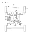
- a hybrid vehicle to which a control apparatus according to a first embodiment of the present invention is mounted includes an engine 100, a generator 200, a PCU (Power Control Unit) 300, a battery 400, a motor 500, and a hybrid ECU (Electronic Control Unit) 600 connected to all of these components.
- the control apparatus according to the embodiment of the present invention is realized by a program executed by hybrid ECU 600. While the present embodiment is described using a hybrid vehicle to which engine 100 is mounted, the present invention is not limited to a hybrid vehicle to which engine 100 is mounted and it is applicable to a hybrid vehicle to which a fuel cell is mounted in place of an engine (a fuel-cell vehicle), an electric vehicle to which only battery 400 is mounted or the like.
- the motive power generated by engine 100 is split by a power split device 700 into two routes. One of them is a route to drive wheels 900 through a reduction gear 800. The other is a route to drive generator 200 for generating power.
- This battery 400 is an assembled battery, in which a plurality of battery modules, each integrally formed of a plurality of battery cells, are serially connected. It should be noted that a capacitor (a condenser) may be used in place of battery 400.
- Motor 500 is a three-phase AC motor. Motor 500 is driven by at least either power accumulated in battery 400 or power generated by generator 200. The drive power of motor 500 is transmitted to wheels 900 via reduction gear 800. Thus, motor 500 assists engine 100 in running the vehicle, or the vehicle runs only by the drive power from motor 500.
- motor 500 In regenerative braking of the hybrid vehicle, motor 500 is driven by wheels 900 via reduction gear 800, and motor 500 is actuated as a generator. Thus, motor 500 serves as a regenerative break that converts braking energy into power. The power generated by motor 500 is accumulated in battery 400 via inverter 302.
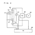
- Hybrid ECU 600 includes CPU (Central Processing Unit) 602, a memory 604 and a counter 606.
- CPU 602 performs operation processing based on a driving state of the vehicle, an acceleration pedal position detected by an acceleration pedal position sensor 1100, a rate of change in the acceleration pedal position, position of the shift lever, SOC of battery 400, a map and a program stored in memory 604 and the like.
- hybrid ECU 600 controls equipment mounted on the vehicle so that the vehicle attains a desired driving state.
- Hybrid ECU 600 calculates charging/discharging power value of battery 400 based on charging/discharging voltage value detected by voltmeter 610 and charging/discharging current value detected by ammeter 612.
- Hybrid ECU 600 calculates SOC of battery 400 by multiplying the charging/discharging current value. The sum of periods during which a charging/discharging current value is detected, and each of those periods during which charging/discharging current value is detected are counted by counter 606.
- the history of the charging/discharging current value detected by ammeter 612 and the periods counted by counter 606 is stored in memory 604.
- the actuating state of battery 400 is stored. It should be noted that, as the periods counted by counter 606, the length of time, the number of time, the traveling distance of the vehicle and the like may be employed as appropriate.
- Hybrid ECU 600 sets a charging power regulation value that is a regulation value of power to be charged to battery 400 (hereinafter “charging power regulation value” is expressed as W(IN)), and a discharging power regulation value that is a regulation value of power to be discharged from battery 400 (hereinafter “discharging power regulation value” is expressed as W(OUT)).
- the charging power value to battery 400, and the discharging power value from battery 400 are regulated so as not to exceed these W(IN) and W(OUT).
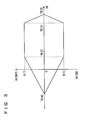
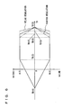
- W(IN) and W(OUT) are set based on battery temperature TB, according to a charging/discharging power regulation map shown in Fig. 3.
- the map shown in Fig. 3 is merely an example, and the present invention is not limited to this map.
- the parameters used to set W(IN) and W(OUT) may be not only battery temperature TB but also SOC of battery 400, voltage and the like, including any combinations thereof.
- As a method for regulating charging/discharging power to/from battery 400 any well-known general technique may be employed, and detailed description thereof is not repeated herein.
- hybrid ECU 600 calculates square-average value I 2 (AVE) of a charge/discharge current value detected by ammeter 612, based on the history stored in memory 604.
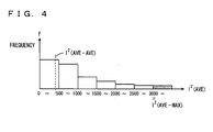
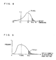
- Fig. 4 is a frequency distribution graph, in which ordinate indicates load frequency, and abscissa indicates square-average value I 2 (AVE) of a charge/discharge current value.
- square-average value I 2 (AVE) of a charge/discharge current value means an averaged value of a square of a charge/discharge current value in an instantaneous period. Any general technique may be used to calculate this value, and therefore detailed description thereof is not repeated herein.
- Hybrid ECU 600 calculates, for every square-average value, a proportion of each period during which square-average value I 2 (AVE) is detected (a period during which a charging/discharging current value corresponding to square-average value I 2 (AVE) is detected) in the sum of periods during which square-average value I 2 (AVE) is calculated (all periods during which a charging/discharging current value is detected) (hereinafter, this proportion is referred to as "load frequency"). Further, hybrid ECU 600 determines a deterioration degree of battery 400 using square-average value I 2 (AVE) of a charge/discharge current value and the load frequency thereof. This method for determining a deterioration degree will be described in detail later.
- the load frequency is not limited to the proportion of each period during which square-average value I 2 (AVE) is detected in the sum of periods during which square-average value I 2 (AVE) is calculated. In place of such a proportion, each period during which square-average value I 2 (AVE) is detected may directly be used.
- hybrid ECU 600 calculates square-average value I 2 (AVE) of a charging/discharging current value and the load frequency.
- hybrid ECU 600 determines whether the deterioration degree of battery 400 is greater than a predetermined degree.
- a predetermined maximum value I 2 (AVE-MAX) in relation to square-average value I 2 (AVE) of a charging/discharging current value is greater than a predetermined frequency
- the deterioration degree of battery 400 is determined to be greater than a predetermined value.
- the deterioration degree of battery 400 may be determined to be greater than a predetermined value when either one of the conditions is satisfied, i.e., when the total of load frequencies of values greater than a predetermined maximum value I 2 (AVE-MAX) is greater than a predetermined frequency, or when averaged value I 2 (AVE-AVE) of the calculated square-average value I 2 (AVE) of a charging/discharging current value is greater than a predetermined value.
- a predetermined value YES at S200
- the process goes to S300. Otherwise, (NO at S200) the process goes to S400.
- hybrid ECU 600 changes the aforementioned charging/discharging power regulation map, and tightens the regulation of charging/discharging power to/from battery 400.
- hybrid ECU 600 determines whether the deterioration degree of battery 400 is smaller than a predetermined degree.
- a predetermined maximum value I 2 (AVE-MAX) in relation to square-average value I 2 (AVE) of a charging/discharging current value is less than a predetermined frequency
- the deterioration degree of battery 400 is determined to be smaller than a predetermined value.
- the deterioration degree of battery 400 may be determined to be smaller than a predetermined value when at least either one of the conditions is satisfied, i.e., when the total of load frequencies (the hatched portion in Fig. 4) of values greater than a predetermined maximum value I 2 (AVE-MAX) in relation to square-average value I 2 (AVE) of a charging/discharging current value is less than a predetermined frequency, or when averaged value I 2 (AVE-AVE) of the calculated square-average value I 2 (AVE) of a charging/discharging current value is smaller than a predetermined value.
- a predetermined value YES at S400
- hybrid ECU 600 changes the aforementioned charging/discharging power regulation map, and relaxes the regulation of charging/discharging power to/from battery 400.
- hybrid ECU 600 that is the control apparatus according to the present embodiment based on the aforementioned configuration and flowcharts will be described.
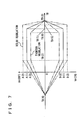
- the charging/discharging regulation map is changes so that the maximum value of W(OUT) and the minimum value ofW(IN) are not changed and the regulation of charging/discharging power to/from battery 400 is tightened (S300).
- the changed charging/discharging regulation map as battery temperature TB becomes higher than TB (6) (TB(6) ⁇ TB(1)), the absolute values of W(IN) and W(OUT) decrease.
- W(IN) and W(OUT) become zero and charging/discharging to/from battery 400 is stopped.
- deterioration degree of battery 400 is determined not greater than a predetermined value (NO at S200), whether the deterioration degree of battery 400 is smaller than a predetermined value is determined (S400).
- a predetermined maximum value I 2 (AVE-MAX) in relation to square-average value I 2 (AVE) of a charging/discharging current value is less than a predetermined frequency
- the deterioration degree of battery 400 is determined to be smaller than a predetermined value (YES at S400).
- the charging/discharging regulation map is changes so that the maximum value of W(OUT) and the minimum value of W(IN) are not changed and the regulation of charging/discharging power to/from battery 400 is relaxed (S500).
- the changed charging/discharging regulation map as battery temperature TB becomes higher than TB (5) (TB(5) > TB(1)), the absolute values of W(IN) and W(OUT) decrease.
- W(IN) and W(OUT) become zero and charging/discharging to/from battery 400 is stopped.
- hybrid ECU that is the control apparatus according to the present embodiment tightens the regulation of charging/discharging power to/from the battery when the deterioration degree of the battery is determined to be greater than a predetermined degree. It relaxes the regulation of charging/discharging power to/from battery when the deterioration degree of the battery is smaller than a predetermined degree.
- loads on the battery can be suppressed when the deterioration degree of the battery is great to suppress deterioration, and increase in loads on the battery can be tolerated when the deterioration degree of the battery is small to make full use of the performance of the battery.
- the charging/discharging regulation map is changes so that the regulation of charging/discharging power to/from battery 400 is tightened (S300).
- a predetermined value YES at S200
- the charging/discharging regulation map is changed so that the regulation of charging/discharging power to/from battery 400 is tightened (S300).
- the absolute values ofW(IN) and W(OUT) decrease.
- battery temperature TB reaches TB (3)
- W(IN) and W(OUT) become zero and charging/discharging to/from battery 400 is stopped.
- the absolute values of W(IN) and W(OUT) are decreased based on the state of battery temperature TB being lower than TB(1). Further, the maximum value of W(OUT) is decreased from A(1) to A(3) (A(1) > A(3)), while the minimum value of W(IN) is increased from B(1) to B(3) (B(1) ⁇ B(3)). In the present embodiment, W(IN) is a negative value and W(OUT) is a positive value.
- the charging/discharging regulation map is changed so that the regulation of charging/discharging power to/from battery 400 is relaxed (S500).
- the absolute values ofW(IN) and W(OUT) decrease.
- W(IN) and W(OUT) become zero and charging/discharging to/from battery 400 is stopped.
- the absolute values of W(IN) and W(OUT) are not decreased unless battery temperature TB becomes higher than TB(1).
- the maximum value of W(OUT) is increased from A(1) to A(2) (A(2) > A(1)), while the minimum value of W(IN) is decreased from B(1) to B(2) (B(2) ⁇ B(1)).
- control apparatus changes the maximum value of W(OUT) and the minimum value ofW(IN). Compared to the control apparatus according to the first embodiment described above, this enables to further tighten and relax the regulation.
- hybrid ECU 600 determines the deterioration degree of battery 400 using square-average value I 2 (AVE) of a charging/discharging current value and the load frequency thereof.
- I 2 square-average value
- the deterioration degree of battery 400 is determined using battery temperature TB and the load frequency thereof.
- Other hardware configuration and process flow are the same as in the first embodiment. Their respective functions are also the same. Accordingly, detailed description thereof will not be repeated here.
- Hybrid ECU 600 calculates the load frequency for each battery temperature TB detected by battery temperature sensor 614.
- the method for calculating load frequency for each battery temperature TB is the same as the method for calculating the load frequency of square-average value I 2 (AVE) of a charging/discharging current value as in the aforementioned first embodiment, and detailed description thereof is not repeated here.
- hybrid ECU 600 determines that the deterioration degree of battery 400 is greater than a predetermined value.
- the deterioration degree of battery 400 may be determined to be greater than a predetermined value when at least either one of the conditions is satisfied, i.e., when the total of the load frequencies of battery temperature TB higher than a predetermined maximum value TB(L) in relation to battery temperature TB is greater than a predetermined frequency, or when averaged value TB(AVE) of the detected battery temperature TB is greater than a predetermined value.
- hybrid ECU 600 determines that the deterioration degree of battery 400 is smaller than a predetermined value.
- the deterioration degree of battery 400 may be determined to be smaller than a predetermined value when at least either one of the conditions is satisfied, i.e., when the total of the load frequencies of battery temperature TB higher than a predetermined maximum value TB(L) in relation to battery temperature TB is less than a predetermined frequency, or when averaged value TB(AVE) of the detected battery temperature TB is smaller than a predetermined value.
- hybrid ECU 600 in the control apparatus according to the present embodiment determines the deterioration degree of battery 400 using battery temperature TB and the load frequency thereof.
- the effect similar to that attained by the control apparatus according to the first embodiment can also be attained.
- hybrid ECU 600 determines the deterioration degree of battery 400 using square-average value I 2 (AVE) of a charging/discharging current value and the load frequency thereof.
- the deterioration degree of battery 400 is determined using a rate of change K in an acceleration pedal position and the load frequency thereof.
- Other hardware configuration and process flow are the same as in the first embodiment. Their respective functions are also the same. Accordingly, detailed description thereof will not be repeated here.
- Hybrid ECU 600 calculates rate of change K in an acceleration pedal position and the load frequency for each rate of change K in an acceleration pedal position, based on an acceleration pedal position detected by an acceleration pedal position sensor 1100.
- the method for calculating load frequency of rate of change K in an acceleration pedal position is the same as the method for calculating load frequency of square-average value I 2 (AVE) of a charging/discharging current value as in the aforementioned first embodiment, and detailed description thereof is not repeated here.
- hybrid ECU 600 determines that the deterioration degree of battery 400 is greater than a predetermined value.
- the deterioration degree of battery 400 may be determined to be greater than a predetermined value when at least either one of the conditions is satisfied, i.e., when the total of the load frequencies of rate of change K in an acceleration pedal position greater than a predetermined maximum value K(L) in relation to rate of change K in an acceleration pedal position is greater than a predetermined frequency, or when averaged value K(AVE) of rate of change K in an acceleration pedal position is greater than a predetermined value.
- the deterioration degree of battery 400 is determined to be smaller than a predetermined value.
- the deterioration degree of battery 400 may be determined to be smaller than a predetermined value when at least either one of the conditions is satisfied, i.e., when the total of load frequencies of rate of change K in an acceleration pedal position greater than a predetermined maximum value K(L) in relation to rate of change K in an acceleration pedal position is less than a predetermined frequency, or when averaged value K(AVE) of rate of change K in an acceleration pedal position is smaller than a predetermined value.
- hybrid ECU 600 in the control apparatus according to the present embodiment determines the deterioration degree of battery 400 using rate of change K in an acceleration pedal position and the load frequency thereof.
- rate of change K rate of change K in an acceleration pedal position and the load frequency thereof.
- a control apparatus according to a fifth embodiment of the present invention will be described.
- the aforementioned hybrid ECU 600 in the control apparatus according to the first embodiment tightens and relaxes the regulation of charging/discharging power by changing the charging/discharging power regulation map.
- regulation of charging/discharging power is tightened and relaxed by changing a threshold value related to a coefficient (hereinafter referred to as regulation coefficient L) by which W(IN) and W(OUT) are multiplied.
- regulation coefficient L a threshold value related to a coefficient
- W(IN) and W(OUT) are multiplied.
- Other hardware configuration and process flow are the same as in the first embodiment. Their respective functions are also the same. Accordingly, detailed description thereof will not be repeated here.
- Hybrid ECU 600 regulates a charging power value to battery 400 and a discharge power value from battery 400 so that they do not exceed values LxW(OUT) and LxW(IN), which are obtained by W(OUT) and W(IN) determined based on the charging/discharging power regulation map shown in Fig. 3 being multiplied by regulation coefficient L (0 ⁇ L ⁇ 1), respectively.
- this regulation coefficient L is set. Regulation coefficient L is determined based on square-average value I 2 (AVE) of a charging/discharging current value.
- Hybrid ECU 600 in the control apparatus tightens and relaxes the regulation of charging/discharging power to/from battery 400 by changing threshold values X and Y with which regulation coefficient L is changed, instead of changing the charging/discharging power regulation map as in the aforementioned first embodiment.
- a predetermined degree YES at S200
- X(1) is decreased to X(2).
- threshold value X may be increased in place of threshold value Y. Additionally, both of the threshold values may be increased.
- hybrid ECU in the control apparatus according to the present embodiment tightens and relaxes the regulation of charging/discharging power to/from the battery by changing threshold values X and Y. With such a configuration also, the effect similar to that attained by the control apparatus according to the first embodiment can be attained.
- the methods for determining the deterioration degree of battery 400 according to any two embodiments can be combined to determine the deterioration degree of battery 400. It is also possible to combine the methods for determining the deterioration degree of battery 400 according to the three embodiments to determine the deterioration degree of battery 400.
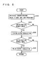
- a hybrid ECU executes a program that includes the steps of: determining whether a deterioration degree of a battery is greater than a predetermined degree (S200); when the deterioration degree of the battery is greater than the predetermined value (YES at S200), tightening the regulation of charging/discharging power to/from the battery (S300); determining whether the deterioration degree of the battery is smaller than the predetermined value (S400) and; when the deterioration degree of the battery is smaller than the predetermined value (YES at S400), relaxing the regulation of charging/discharging power to/from the battery (S500).
Landscapes
- Engineering & Computer Science (AREA)
- Mechanical Engineering (AREA)
- Power Engineering (AREA)
- Transportation (AREA)
- Life Sciences & Earth Sciences (AREA)
- Sustainable Energy (AREA)
- Sustainable Development (AREA)
- Chemical & Material Sciences (AREA)
- Combustion & Propulsion (AREA)
- Automation & Control Theory (AREA)
- Charge And Discharge Circuits For Batteries Or The Like (AREA)
- Electric Propulsion And Braking For Vehicles (AREA)
- Secondary Cells (AREA)
Applications Claiming Priority (2)
| Application Number | Priority Date | Filing Date | Title |
|---|---|---|---|
| JP2003359126A JP4134877B2 (ja) | 2003-10-20 | 2003-10-20 | 蓄電機構の制御装置 |
| JP2003359126 | 2003-10-20 |
Publications (3)
| Publication Number | Publication Date |
|---|---|
| EP1526627A2 true EP1526627A2 (de) | 2005-04-27 |
| EP1526627A3 EP1526627A3 (de) | 2007-06-13 |
| EP1526627B1 EP1526627B1 (de) | 2017-08-16 |
Family
ID=34386456
Family Applications (1)
| Application Number | Title | Priority Date | Filing Date |
|---|---|---|---|
| EP04024853.6A Expired - Lifetime EP1526627B1 (de) | 2003-10-20 | 2004-10-19 | Steuergerät für Elektrizitätsladungsmechanismus |
Country Status (3)
| Country | Link |
|---|---|
| US (1) | US7482779B2 (de) |
| EP (1) | EP1526627B1 (de) |
| JP (1) | JP4134877B2 (de) |
Cited By (11)
| Publication number | Priority date | Publication date | Assignee | Title |
|---|---|---|---|---|
| WO2007093882A3 (en) * | 2006-02-15 | 2007-10-18 | Toyota Motor Co Ltd | Controller and control method for charging of the secondary battery |
| DE102007007925A1 (de) * | 2007-02-17 | 2008-08-21 | Volkswagen Ag | Parallel-Hybridantrieb in einem Kraftfahrzeug und Verfahren zur Ansteuerung eines Parallel-Hybridantriebes |
| AT508875A3 (de) * | 2011-01-21 | 2012-06-15 | Avl List Gmbh | Betrieb eines elektrischen energiespeichers für ein fahrzeug |
| US8810210B2 (en) | 2009-04-01 | 2014-08-19 | Sumitomo Heavy Industries, Ltd. | Hybrid working machine |
| WO2015011534A3 (en) * | 2013-07-25 | 2015-07-16 | Toyota Jidosha Kabushiki Kaisha | Control device and control method for electrical storage device |
| EP2571093A4 (de) * | 2010-05-14 | 2015-10-07 | Toyota Motor Co Ltd | Steuerungsvorrichtung und steuerungsverfahren einer sekundärbatterie |
| EP2930820A4 (de) * | 2012-12-05 | 2015-11-25 | Panasonic Ip Man Co Ltd | Vorrichtung zur ladungs- und entladungsverwaltung, stromversorger, stromspeichervorrichtung und programm |
| WO2015180910A1 (de) * | 2014-05-28 | 2015-12-03 | Robert Bosch Gmbh | Verfahren zum batteriemanagement und batteriemanagementsystem |
| EP2100765A3 (de) * | 2008-02-29 | 2016-08-24 | Mitsubishi Jidosha Kogyo Kabushiki Kaisha | Batteriemanagementsteuersystem |
| EP3115249A1 (de) * | 2015-07-07 | 2017-01-11 | Hitachi Construction Machinery Co., Ltd. | Steuerungsvorrichtung für die batterie einer hybriden baumaschine |
| AT525061A4 (de) * | 2021-08-10 | 2022-12-15 | Avl List Gmbh | Kontrollverfahren für eine Kontrolle einer Abgabeleistung einer Batterievorrichtung und einer Betriebsleistung eines Brennstoffzellensystems |
Families Citing this family (51)
| Publication number | Priority date | Publication date | Assignee | Title |
|---|---|---|---|---|
| US8878539B2 (en) * | 2004-04-06 | 2014-11-04 | Robert Bosch Gmbh | State of charge tracking system for battery systems based on relaxation voltage |
| JP4327692B2 (ja) * | 2004-09-30 | 2009-09-09 | トヨタ自動車株式会社 | 二次電池の充放電制御装置 |
| JP4232751B2 (ja) * | 2005-03-16 | 2009-03-04 | トヨタ自動車株式会社 | ハイブリッド型車両 |
| TWI333288B (en) | 2005-06-14 | 2010-11-11 | Lg Chemical Ltd | Method and apparatus of controlling for charging/discharging voltage of battery |
| JP4211806B2 (ja) * | 2006-06-07 | 2009-01-21 | トヨタ自動車株式会社 | 車両駆動システムおよびそれを備える車両 |
| JP5054338B2 (ja) * | 2006-07-20 | 2012-10-24 | 本田技研工業株式会社 | 車両用電源の制御装置およびその制御方法 |
| JP4265629B2 (ja) * | 2006-08-01 | 2009-05-20 | トヨタ自動車株式会社 | 二次電池の充放電制御装置およびそれを搭載したハイブリッド車両 |
| JP4811301B2 (ja) * | 2007-03-06 | 2011-11-09 | トヨタ自動車株式会社 | 二次電池の入出力制御装置、および車両 |
| US8405361B2 (en) * | 2007-09-21 | 2013-03-26 | Qualcomm Incorporated | System and method for charging a rechargeable battery |
| WO2009042857A2 (en) * | 2007-09-26 | 2009-04-02 | Tesla Motors, Inc. | Operation of a range extended electric vehicle |
| JP4494453B2 (ja) * | 2007-11-13 | 2010-06-30 | トヨタ自動車株式会社 | 二次電池の制御装置および制御方法 |
| US8288885B2 (en) * | 2008-06-03 | 2012-10-16 | Honeywell International Inc. | Method and system for improving electrical load regeneration management of an aircraft |
| EP2363329B1 (de) * | 2008-11-05 | 2018-08-15 | Toyota Jidosha Kabushiki Kaisha | Hybridfahrzeug und hybridfahrzeugsteuerverfahren |
| JP5470829B2 (ja) * | 2008-12-11 | 2014-04-16 | トヨタ自動車株式会社 | リチウムイオン電池の状態を判別する判別装置 |
| KR101307198B1 (ko) | 2009-01-28 | 2013-09-11 | 스미도모쥬기가이고교 가부시키가이샤 | 하이브리드형 작업기계 및 축전제어장치 |
| JP2010193630A (ja) * | 2009-02-18 | 2010-09-02 | Sumitomo Heavy Ind Ltd | 蓄電制御装置及び作業機械 |
| US8013569B2 (en) * | 2009-03-06 | 2011-09-06 | Sustainable Structures LLC | Renewable energy vehicle charging station |
| JP5170781B2 (ja) * | 2009-10-13 | 2013-03-27 | 本田技研工業株式会社 | ハイブリッド車両 |
| JP5789736B2 (ja) * | 2009-10-23 | 2015-10-07 | パナソニックIpマネジメント株式会社 | 電力供給装置 |
| DE102009057174A1 (de) | 2009-12-05 | 2011-06-09 | Volkswagen Ag | Verfahren und Vorrichtung zur Steuerung von Hybrid-Funktionen in einem Kraftfahrzeug |
| US20110276290A1 (en) * | 2010-05-07 | 2011-11-10 | Chih-Peng Chang | Device for counting and storing automatically number of times of usage of cell |
| US11397215B2 (en) | 2010-05-21 | 2022-07-26 | Qnovo Inc. | Battery adaptive charging using battery physical phenomena |
| US11397216B2 (en) | 2010-05-21 | 2022-07-26 | Qnovo Inc. | Battery adaptive charging using a battery model |
| US12081057B2 (en) | 2010-05-21 | 2024-09-03 | Qnovo Inc. | Method and circuitry to adaptively charge a battery/cell |
| WO2011158381A1 (ja) * | 2010-06-18 | 2011-12-22 | トヨタ自動車株式会社 | 劣化度合判定装置 |
| JP5343168B2 (ja) * | 2010-06-24 | 2013-11-13 | パナソニック株式会社 | 電池の劣化度を取得するための方法及びそのシステム |
| JP2012125051A (ja) * | 2010-12-08 | 2012-06-28 | Daimler Ag | 電気自動車の電源制御装置 |
| JP5321757B2 (ja) * | 2011-01-27 | 2013-10-23 | トヨタ自動車株式会社 | 蓄電装置の制御装置および制御方法 |
| US20130297244A1 (en) * | 2011-02-28 | 2013-11-07 | Mitsubishi Heavy Industries, Ltd. | Secondary battery lifetime prediction apparatus, battery system and secondary battery lifetime prediction method |
| JP5659990B2 (ja) * | 2011-09-12 | 2015-01-28 | 三菱自動車工業株式会社 | 電池温度調節装置 |
| KR101605491B1 (ko) * | 2011-09-28 | 2016-03-22 | 도요타 지도샤(주) | 비수 이차 전지의 제어 장치 및 제어 방법 |
| JP5720554B2 (ja) * | 2011-12-13 | 2015-05-20 | トヨタ自動車株式会社 | 非水二次電池の制御装置および制御方法 |
| JP5880008B2 (ja) * | 2011-12-19 | 2016-03-08 | マツダ株式会社 | 車載用電源の制御装置 |
| CN103176129B (zh) * | 2011-12-20 | 2016-03-02 | 财团法人车辆研究测试中心 | 电动交通工具的电池残余电量估测方法 |
| US9007030B2 (en) * | 2011-12-23 | 2015-04-14 | Automotive Research & Testing Center | Method of estimating battery remaining power in electric vehicle |
| JP5842607B2 (ja) * | 2011-12-28 | 2016-01-13 | トヨタ自動車株式会社 | 非水二次電池の制御装置および制御方法 |
| JP5716691B2 (ja) * | 2012-02-15 | 2015-05-13 | トヨタ自動車株式会社 | 電池システムおよび非水二次電池の充放電制御方法 |
| DE102013211543A1 (de) * | 2013-06-19 | 2014-12-24 | Robert Bosch Gmbh | Verfahren zum alterungs- und energieeffizienten Betrieb insbesondere eines Kraftfahrzeugs |
| JP6225691B2 (ja) * | 2013-12-18 | 2017-11-08 | 三菱自動車工業株式会社 | バッテリ制御装置 |
| US9331484B2 (en) * | 2014-03-06 | 2016-05-03 | Nissan North America, Inc. | Systems and methods of controlling battery deterioration by controlling battery temperature during power exchange |
| US9331503B2 (en) * | 2014-03-06 | 2016-05-03 | Nissan North America, Inc. | Systems and methods of controlling battery deterioration by controlling battery state-of-health during power exchange |
| WO2017129259A1 (en) * | 2016-01-29 | 2017-08-03 | Toyota Motor Europe Nv/Sa | Control device and method for discharging a rechargeable battery |
| JP6504100B2 (ja) * | 2016-04-12 | 2019-04-24 | トヨタ自動車株式会社 | バッテリ放電制御装置 |
| KR102592332B1 (ko) * | 2016-06-17 | 2023-10-19 | 주식회사 엘지에너지솔루션 | 배터리 관리 시스템, 배터리 팩 및 배터리 충전 방법 |
| KR102726191B1 (ko) | 2016-10-05 | 2024-11-06 | 삼성전자주식회사 | 배터리 상태 추정 장치 및 방법 |
| US12531283B2 (en) | 2018-11-07 | 2026-01-20 | Qnovo Inc. | Battery adaptive charging using battery physical phenomena |
| JP6892895B2 (ja) * | 2019-05-28 | 2021-06-23 | 本田技研工業株式会社 | 管理装置、管理方法、およびプログラム |
| US11509153B2 (en) * | 2019-07-18 | 2022-11-22 | Save The Planet Co., Ltd. | Charge/discharge control method for storage system and charge/discharge control device |
| JP7469219B2 (ja) * | 2020-12-14 | 2024-04-16 | 本田技研工業株式会社 | 電源システム |
| JP7598273B2 (ja) * | 2021-03-18 | 2024-12-11 | 株式会社Subaru | 車両 |
| JP7653333B2 (ja) * | 2021-09-07 | 2025-03-28 | 日立グローバルライフソリューションズ株式会社 | 二次電池の制御装置及び制御方法並びに当該制御装置を備えた充電式掃除機 |
Citations (5)
| Publication number | Priority date | Publication date | Assignee | Title |
|---|---|---|---|---|
| JPH07255133A (ja) | 1994-03-15 | 1995-10-03 | Nissan Motor Co Ltd | 2次電池の充放電制御装置 |
| EP0841208A1 (de) | 1996-05-24 | 1998-05-13 | Hino Jidosha Kogyo Kabushiki Kaisha | Regler für eine fahrzeug-eigene batterie |
| US5965991A (en) | 1996-06-14 | 1999-10-12 | Hino Jidosha Kogyo Kabushiki Kaisha | Control system for a vehicle-mounted battery |
| US6232744B1 (en) | 1999-02-24 | 2001-05-15 | Denso Corporation | Method of controlling battery condition of self-generation electric vehicle |
| US20020157882A1 (en) | 2000-03-21 | 2002-10-31 | Asami Kubo | Control device for hybrid vehicle |
Family Cites Families (8)
| Publication number | Priority date | Publication date | Assignee | Title |
|---|---|---|---|---|
| JP3351683B2 (ja) | 1996-06-21 | 2002-12-03 | 日野自動車株式会社 | 車載電池の制御装置 |
| JP3436090B2 (ja) * | 1997-02-14 | 2003-08-11 | トヨタ自動車株式会社 | 電気式駆動車両 |
| JP3757602B2 (ja) | 1998-02-10 | 2006-03-22 | 日産自動車株式会社 | 電池温度保護制御装置 |
| JP3360613B2 (ja) * | 1998-06-25 | 2002-12-24 | トヨタ自動車株式会社 | 電池制御装置 |
| JP2003009406A (ja) | 2001-06-22 | 2003-01-10 | Matsushita Electric Ind Co Ltd | 二次電池の状態演算装置 |
| JP3638263B2 (ja) | 2001-09-10 | 2005-04-13 | 本田技研工業株式会社 | 車両駆動装置 |
| JP3801045B2 (ja) | 2001-12-25 | 2006-07-26 | トヨタ自動車株式会社 | 自動車用のバッテリ充放電制御装置 |
| JP3949488B2 (ja) | 2002-03-29 | 2007-07-25 | 本田技研工業株式会社 | 蓄電池の寿命予測装置および蓄電池の制御装置 |
-
2003
- 2003-10-20 JP JP2003359126A patent/JP4134877B2/ja not_active Expired - Lifetime
-
2004
- 2004-10-12 US US10/961,270 patent/US7482779B2/en not_active Expired - Lifetime
- 2004-10-19 EP EP04024853.6A patent/EP1526627B1/de not_active Expired - Lifetime
Patent Citations (5)
| Publication number | Priority date | Publication date | Assignee | Title |
|---|---|---|---|---|
| JPH07255133A (ja) | 1994-03-15 | 1995-10-03 | Nissan Motor Co Ltd | 2次電池の充放電制御装置 |
| EP0841208A1 (de) | 1996-05-24 | 1998-05-13 | Hino Jidosha Kogyo Kabushiki Kaisha | Regler für eine fahrzeug-eigene batterie |
| US5965991A (en) | 1996-06-14 | 1999-10-12 | Hino Jidosha Kogyo Kabushiki Kaisha | Control system for a vehicle-mounted battery |
| US6232744B1 (en) | 1999-02-24 | 2001-05-15 | Denso Corporation | Method of controlling battery condition of self-generation electric vehicle |
| US20020157882A1 (en) | 2000-03-21 | 2002-10-31 | Asami Kubo | Control device for hybrid vehicle |
Cited By (18)
| Publication number | Priority date | Publication date | Assignee | Title |
|---|---|---|---|---|
| WO2007093882A3 (en) * | 2006-02-15 | 2007-10-18 | Toyota Motor Co Ltd | Controller and control method for charging of the secondary battery |
| CN101384461B (zh) * | 2006-02-15 | 2013-07-31 | 丰田自动车株式会社 | 用于二次电池充电/放电的控制器和控制方法 |
| DE102007007925A1 (de) * | 2007-02-17 | 2008-08-21 | Volkswagen Ag | Parallel-Hybridantrieb in einem Kraftfahrzeug und Verfahren zur Ansteuerung eines Parallel-Hybridantriebes |
| EP2100765A3 (de) * | 2008-02-29 | 2016-08-24 | Mitsubishi Jidosha Kogyo Kabushiki Kaisha | Batteriemanagementsteuersystem |
| US8810210B2 (en) | 2009-04-01 | 2014-08-19 | Sumitomo Heavy Industries, Ltd. | Hybrid working machine |
| EP2571093A4 (de) * | 2010-05-14 | 2015-10-07 | Toyota Motor Co Ltd | Steuerungsvorrichtung und steuerungsverfahren einer sekundärbatterie |
| AT508875A3 (de) * | 2011-01-21 | 2012-06-15 | Avl List Gmbh | Betrieb eines elektrischen energiespeichers für ein fahrzeug |
| AT508875B1 (de) * | 2011-01-21 | 2013-03-15 | Avl List Gmbh | Betrieb eines elektrischen energiespeichers für ein fahrzeug |
| EP2930820A4 (de) * | 2012-12-05 | 2015-11-25 | Panasonic Ip Man Co Ltd | Vorrichtung zur ladungs- und entladungsverwaltung, stromversorger, stromspeichervorrichtung und programm |
| WO2015011534A3 (en) * | 2013-07-25 | 2015-07-16 | Toyota Jidosha Kabushiki Kaisha | Control device and control method for electrical storage device |
| WO2015180910A1 (de) * | 2014-05-28 | 2015-12-03 | Robert Bosch Gmbh | Verfahren zum batteriemanagement und batteriemanagementsystem |
| US10147980B2 (en) | 2014-05-28 | 2018-12-04 | Robert Bosch Gmbh | Method for battery management and battery management system |
| EP3115249A1 (de) * | 2015-07-07 | 2017-01-11 | Hitachi Construction Machinery Co., Ltd. | Steuerungsvorrichtung für die batterie einer hybriden baumaschine |
| CN106337456A (zh) * | 2015-07-07 | 2017-01-18 | 日立建机株式会社 | 工程机械的控制装置 |
| US10047501B2 (en) | 2015-07-07 | 2018-08-14 | Hitachi Construction Machinery Co., Ltd. | Control device of construction machine |
| CN106337456B (zh) * | 2015-07-07 | 2018-10-19 | 日立建机株式会社 | 工程机械的控制装置 |
| AT525061A4 (de) * | 2021-08-10 | 2022-12-15 | Avl List Gmbh | Kontrollverfahren für eine Kontrolle einer Abgabeleistung einer Batterievorrichtung und einer Betriebsleistung eines Brennstoffzellensystems |
| AT525061B1 (de) * | 2021-08-10 | 2022-12-15 | Avl List Gmbh | Kontrollverfahren für eine Kontrolle einer Abgabeleistung einer Batterievorrichtung und einer Betriebsleistung eines Brennstoffzellensystems |
Also Published As
| Publication number | Publication date |
|---|---|
| JP2005124353A (ja) | 2005-05-12 |
| JP4134877B2 (ja) | 2008-08-20 |
| US20050083017A1 (en) | 2005-04-21 |
| EP1526627B1 (de) | 2017-08-16 |
| US7482779B2 (en) | 2009-01-27 |
| EP1526627A3 (de) | 2007-06-13 |
Similar Documents
| Publication | Publication Date | Title |
|---|---|---|
| US7482779B2 (en) | Control apparatus of electricity accumulation mechanism | |
| US8102146B2 (en) | Remaining-amount estimation device and method for secondary battery | |
| US10381695B2 (en) | Cooling system for secondary battery | |
| JP3967043B2 (ja) | ハイブリッド車両の制御装置 | |
| US20100241376A1 (en) | Control apparatus and control method for secondary battery | |
| US20150046007A1 (en) | Electric power generation control system for hybrid automobile | |
| US10011188B2 (en) | Hybrid vehicle | |
| US20140236405A1 (en) | Controller for hybrid vehicle | |
| US9252630B2 (en) | Battery charge control apparatus | |
| KR20140079156A (ko) | 하이브리드 차량의 모터의 토크 결정 방법 및 시스템 | |
| JP4026013B2 (ja) | トルク制御装置 | |
| US8392043B2 (en) | Powertrain for an electric vehicle and method of managing electric power flow in a vehicle powertrain | |
| JPH07236203A (ja) | 電気自動車の制御装置 | |
| JP5411237B2 (ja) | ハイブリッド車両の制御装置 | |
| JP2001211507A (ja) | ハイブリッド車両の制御装置 | |
| JP3772875B2 (ja) | ハイブリッド車両の制御装置 | |
| JP3628912B2 (ja) | バッテリ充電状態検出装置 | |
| JP3772876B2 (ja) | ハイブリッド車両の制御装置 | |
| US20260112908A1 (en) | Battery system |
Legal Events
| Date | Code | Title | Description |
|---|---|---|---|
| PUAI | Public reference made under article 153(3) epc to a published international application that has entered the european phase |
Free format text: ORIGINAL CODE: 0009012 |
|
| 17P | Request for examination filed |
Effective date: 20041019 |
|
| AK | Designated contracting states |
Kind code of ref document: A2 Designated state(s): AT BE BG CH CY CZ DE DK EE ES FI FR GB GR HU IE IT LI LU MC NL PL PT RO SE SI SK TR |
|
| AX | Request for extension of the european patent |
Extension state: AL HR LT LV MK |
|
| PUAL | Search report despatched |
Free format text: ORIGINAL CODE: 0009013 |
|
| AK | Designated contracting states |
Kind code of ref document: A3 Designated state(s): AT BE BG CH CY CZ DE DK EE ES FI FR GB GR HU IE IT LI LU MC NL PL PT RO SE SI SK TR |
|
| AX | Request for extension of the european patent |
Extension state: AL HR LT LV MK |
|
| RIC1 | Information provided on ipc code assigned before grant |
Ipc: B60L 11/18 20060101ALI20070504BHEP Ipc: H02J 7/14 20060101AFI20050128BHEP Ipc: B60K 6/04 20060101ALI20070504BHEP Ipc: H02J 7/00 20060101ALI20070504BHEP |
|
| AKX | Designation fees paid |
Designated state(s): DE FR |
|
| RAP1 | Party data changed (applicant data changed or rights of an application transferred) |
Owner name: TOYOTA JIDOSHA KABUSHIKI KAISHA |
|
| 17Q | First examination report despatched |
Effective date: 20130619 |
|
| GRAP | Despatch of communication of intention to grant a patent |
Free format text: ORIGINAL CODE: EPIDOSNIGR1 |
|
| RIC1 | Information provided on ipc code assigned before grant |
Ipc: B60K 6/20 20071001ALI20170327BHEP Ipc: B60L 11/18 20060101ALI20170327BHEP Ipc: H02J 7/14 20060101AFI20170327BHEP Ipc: H02J 7/00 20060101ALI20170327BHEP |
|
| INTG | Intention to grant announced |
Effective date: 20170418 |
|
| RIN1 | Information on inventor provided before grant (corrected) |
Inventor name: SUZUKI, YUSUKE |
|
| GRAS | Grant fee paid |
Free format text: ORIGINAL CODE: EPIDOSNIGR3 |
|
| GRAA | (expected) grant |
Free format text: ORIGINAL CODE: 0009210 |
|
| AK | Designated contracting states |
Kind code of ref document: B1 Designated state(s): DE FR |
|
| REG | Reference to a national code |
Ref country code: DE Ref legal event code: R096 Ref document number: 602004051661 Country of ref document: DE |
|
| REG | Reference to a national code |
Ref country code: DE Ref legal event code: R097 Ref document number: 602004051661 Country of ref document: DE |
|
| PLBE | No opposition filed within time limit |
Free format text: ORIGINAL CODE: 0009261 |
|
| STAA | Information on the status of an ep patent application or granted ep patent |
Free format text: STATUS: NO OPPOSITION FILED WITHIN TIME LIMIT |
|
| 26N | No opposition filed |
Effective date: 20180517 |
|
| REG | Reference to a national code |
Ref country code: DE Ref legal event code: R084 Ref document number: 602004051661 Country of ref document: DE |
|
| REG | Reference to a national code |
Ref country code: FR Ref legal event code: ST Effective date: 20180629 |
|
| PG25 | Lapsed in a contracting state [announced via postgrant information from national office to epo] |
Ref country code: FR Free format text: LAPSE BECAUSE OF NON-PAYMENT OF DUE FEES Effective date: 20171031 |
|
| RIC2 | Information provided on ipc code assigned after grant |
Ipc: B60K 6/20 20071001ALI20170327BHEP Ipc: H02J 7/14 20060101AFI20170327BHEP Ipc: H02J 7/00 20060101ALI20170327BHEP Ipc: B60L 11/18 20060101ALI20170327BHEP |
|
| P01 | Opt-out of the competence of the unified patent court (upc) registered |
Effective date: 20230427 |
|
| PGFP | Annual fee paid to national office [announced via postgrant information from national office to epo] |
Ref country code: DE Payment date: 20230830 Year of fee payment: 20 |
|
| REG | Reference to a national code |
Ref country code: DE Ref legal event code: R071 Ref document number: 602004051661 Country of ref document: DE |