EP1526613B1 - Balkenartiger verbindungsanschluss des steckertyps und verfahren zu seiner herstellung - Google Patents
Balkenartiger verbindungsanschluss des steckertyps und verfahren zu seiner herstellung Download PDFInfo
- Publication number
- EP1526613B1 EP1526613B1 EP03741322A EP03741322A EP1526613B1 EP 1526613 B1 EP1526613 B1 EP 1526613B1 EP 03741322 A EP03741322 A EP 03741322A EP 03741322 A EP03741322 A EP 03741322A EP 1526613 B1 EP1526613 B1 EP 1526613B1
- Authority
- EP
- European Patent Office
- Prior art keywords
- terminal
- rod
- metal plate
- connecting terminal
- raised portions
- Prior art date
- Legal status (The legal status is an assumption and is not a legal conclusion. Google has not performed a legal analysis and makes no representation as to the accuracy of the status listed.)
- Expired - Lifetime
Links
- 238000000034 method Methods 0.000 title claims description 5
- 239000002184 metal Substances 0.000 claims abstract description 22
- 238000005452 bending Methods 0.000 claims description 9
- 238000004519 manufacturing process Methods 0.000 claims description 6
- 238000004080 punching Methods 0.000 claims description 3
- 238000005096 rolling process Methods 0.000 abstract description 3
- 230000000717 retained effect Effects 0.000 abstract 1
- 238000000465 moulding Methods 0.000 description 3
- 239000004020 conductor Substances 0.000 description 2
- 240000008042 Zea mays Species 0.000 description 1
- 235000005824 Zea mays ssp. parviglumis Nutrition 0.000 description 1
- 235000002017 Zea mays subsp mays Nutrition 0.000 description 1
- 230000006835 compression Effects 0.000 description 1
- 238000007906 compression Methods 0.000 description 1
- 238000000748 compression moulding Methods 0.000 description 1
- 235000005822 corn Nutrition 0.000 description 1
- 239000012467 final product Substances 0.000 description 1
- 239000003381 stabilizer Substances 0.000 description 1
- 239000007858 starting material Substances 0.000 description 1
Images

Classifications
-
- H—ELECTRICITY
- H01—ELECTRIC ELEMENTS
- H01R—ELECTRICALLY-CONDUCTIVE CONNECTIONS; STRUCTURAL ASSOCIATIONS OF A PLURALITY OF MUTUALLY-INSULATED ELECTRICAL CONNECTING ELEMENTS; COUPLING DEVICES; CURRENT COLLECTORS
- H01R13/00—Details of coupling devices of the kinds covered by groups H01R12/70 or H01R24/00 - H01R33/00
- H01R13/02—Contact members
- H01R13/04—Pins or blades for co-operation with sockets
- H01R13/05—Resilient pins or blades
- H01R13/055—Resilient pins or blades co-operating with sockets having a rectangular transverse section
-
- H—ELECTRICITY
- H01—ELECTRIC ELEMENTS
- H01R—ELECTRICALLY-CONDUCTIVE CONNECTIONS; STRUCTURAL ASSOCIATIONS OF A PLURALITY OF MUTUALLY-INSULATED ELECTRICAL CONNECTING ELEMENTS; COUPLING DEVICES; CURRENT COLLECTORS
- H01R43/00—Apparatus or processes specially adapted for manufacturing, assembling, maintaining, or repairing of line connectors or current collectors or for joining electric conductors
- H01R43/16—Apparatus or processes specially adapted for manufacturing, assembling, maintaining, or repairing of line connectors or current collectors or for joining electric conductors for manufacturing contact members, e.g. by punching and by bending
-
- H—ELECTRICITY
- H01—ELECTRIC ELEMENTS
- H01R—ELECTRICALLY-CONDUCTIVE CONNECTIONS; STRUCTURAL ASSOCIATIONS OF A PLURALITY OF MUTUALLY-INSULATED ELECTRICAL CONNECTING ELEMENTS; COUPLING DEVICES; CURRENT COLLECTORS
- H01R4/00—Electrically-conductive connections between two or more conductive members in direct contact, i.e. touching one another; Means for effecting or maintaining such contact; Electrically-conductive connections having two or more spaced connecting locations for conductors and using contact members penetrating insulation
- H01R4/10—Electrically-conductive connections between two or more conductive members in direct contact, i.e. touching one another; Means for effecting or maintaining such contact; Electrically-conductive connections having two or more spaced connecting locations for conductors and using contact members penetrating insulation effected solely by twisting, wrapping, bending, crimping, or other permanent deformation
- H01R4/18—Electrically-conductive connections between two or more conductive members in direct contact, i.e. touching one another; Means for effecting or maintaining such contact; Electrically-conductive connections having two or more spaced connecting locations for conductors and using contact members penetrating insulation effected solely by twisting, wrapping, bending, crimping, or other permanent deformation by crimping
- H01R4/183—Electrically-conductive connections between two or more conductive members in direct contact, i.e. touching one another; Means for effecting or maintaining such contact; Electrically-conductive connections having two or more spaced connecting locations for conductors and using contact members penetrating insulation effected solely by twisting, wrapping, bending, crimping, or other permanent deformation by crimping for cylindrical elongated bodies, e.g. cables having circular cross-section
- H01R4/184—Electrically-conductive connections between two or more conductive members in direct contact, i.e. touching one another; Means for effecting or maintaining such contact; Electrically-conductive connections having two or more spaced connecting locations for conductors and using contact members penetrating insulation effected solely by twisting, wrapping, bending, crimping, or other permanent deformation by crimping for cylindrical elongated bodies, e.g. cables having circular cross-section comprising a U-shaped wire-receiving portion
Definitions
- the present invention relates to a male type rod-like connecting terminal of an electric connector, which is engaged with a corresponding female type connecting terminal of the electric connector, and also relates to a method of manufacturing such a male type rod-like connecting terminal.
- a small male type rod-like connecting terminal of this kind is disclosed in JPA 11-329545 , in which a tip portion has a rectangular cross section.
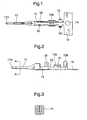
- Fig. 5 shows this known male type rod-like connecting terminal while a portion thereof has been dispensed with for the sake of clarity.
- the connecting terminal 1 is integrally formed by bending a thin conductive metal plate and includes a rod-like terminal connecting portion 2 which is to be electrically coupled with a corresponding female type connecting terminal.
- the connecting terminal further includes a U-shaped wire clamping portion to which is clamped an electric wire extending in an opposite direction to the terminal connecting portion 2.
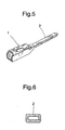
- the connecting terminal portion 2 has a hollow cylindrical shape as illustrated in Fig. 6 . That is to say, the connecting terminal portion 2 is formed by bending a metal plate to have a given thickness.
- the above mentioned terminal connecting portion 2 of the male type rod-like connecting terminal 1 is relatively delicate against force and vibration added up and down and, moreover, has such a drawback that it might be bent and in an extreme case, might be broken at a root portion of the terminal connecting portion 2 when strong force and vibration are continuously applied, because the terminal portion is relatively flat and metal plates standing side by side are limited in number and in width.
- US-A-6 077 131 discloses a male rod-like connecting terminal according to the preamble of claim 1.
- a male type rod-like connecting terminal of an electrical connector comprises the features of claim 1.
- a method of manufacturing a male type rod-like connecting terminal of an electrical connector comprises the features of claim 4.
- Fig. 1 is a plan view and Fig. 2 is a side view showing an embodiment of the male type rod-like connecting terminal according to the present invention, and Fig. 3 is an enlarged cross sectional view cut along an A-A line in Fig. 2 .
- the male type rod-like connecting terminal 10 of an electrical connector is formed by punching a thin electrically conductive metal plate into a given pattern and by folding the metal plate such that the male type rod-like connecting terminal 10 includes a rod-like terminal connecting portion 11 which is provided at a front end and is to be connected to a corresponding female type connecting terminal of the electrical connector, a medium portion 12 for securing the connecting terminal to a housing of the electrical connector and a wire clamping portion 13 having a U-shape cross section for connecting an electric wire.
- the wire clamping portion 13 is connected to a connecting strip 15 including pilot holes 14, which serve as a positional standard for molding the connecting terminal with the aid of a forming press and connecting the electric wire.
- the wire clamping portion 13 includes a core conductor clamping portion 13a for clamping a core conductor of the electric wire and a sheath clamping portion 13b for clamping a sheath of the electric wire.
- a reference numeral 16 denotes a stabilizer for keeping a stable posture of the connecting terminal 10 upon accommodating the connecting terminal in the housing.
- the terminal connecting portion 11 is formed to have a square cross section by folding lateral sides of a strip portion along the longitudinal direction, said strip portion being formed in an electrically conductive metal plate by punching, and a tip 11a of the connecting terminal is processed into a square corn shape by compression molding.
- Fig. 4 is an explanatory view illustrating successive molding processes for forming the terminal connecting portion 11.
- a strip portion 21 having a given width of a thin metal plate having a thickness of, for example 0.2 mm is pressed by rolling into a thickness of 0.16mm as depicted in Fig. 4(b) .
- both lateral side portions 22, 23 of the strip portion 21 extending in the longitudinal direction are raised from a base portion 24 as shown in Fig. 4(c) , and the thus raised side portions 22, 23 are bent inwardly toward the base portion 24 as shown in Fig. 4(d) such that the side portions 22, 23 are folded on the base portion 24 as illustrated in Fig. 4(e) .
- the thus folded both lateral side portions 22, 23 are raised together with the base portion 24 as shown in Fig. 4(f) such that the both lateral side portions are closely contacted with each other.
- the thus folded body is compressed by mechanical compression applied from all directions to have a square cross section having a side of 0.64mm as shown Fig. 3 .
- the base portion 24 may be slightly inflated downward as illustrated in Fig. 4(f) .
- the rolling process shown in Fig.4 (a) can be dispensed with.
- the terminal connecting portion has to be compressed to have a square cross section with a sided of 0.64 mm by the process depicted in Fig. 4(f) .
- the terminal connecting portion 11 of the male type rod-like connecting terminal 10 is formed by folding a thin electrically conductive metal plate such that the terminal connecting portion 11 has no hollow portion and is formed into the rod-like member with a square cross section having a sufficient width in a vertical direction, and therefore the terminal connecting portion 11 thus produced can have thicker sides even though the starting material, i.e. the electrically conductive metal plate is very thin and the connecting terminal is hardly bent vertically or broken.
- the terminal connecting portion is formed by bending and folding an electrically conductive metal plate into the rod-shape with a substantially square cross section, and thus a mechanical strength of the terminal connecting portion can be improved especially in the vertical direction.
Landscapes
- Engineering & Computer Science (AREA)
- Manufacturing & Machinery (AREA)
- Manufacturing Of Electrical Connectors (AREA)
- Connections Effected By Soldering, Adhesion, Or Permanent Deformation (AREA)
Claims (4)
- Stabartiger Einsteck-Verbindungsanschluss (10) eines elektrischen Verbinders, der einen stabartigen Anschluss-Verbindungsabschnitt (11) umfasst, der an einem vorderen Ende des Verbindungsanschlusses vorhanden ist, wobei der stabartige Anschluss-Verbindungsabschnitt mit einem entsprechenden Aufnahme-Verbindungsanschluss des elektrischen Verbinders verbunden werden kann und ausgebildet wird, indem eine Platte aus elektrisch leitendem Metall gebogen und gefalzt wird, dadurch gekennzeichnet, dass der Anschluss-Verbindungsabschnitt (11) aus einem stabartigen Element besteht, das einen im Wesentlichen quadratischen Querschnitt hat, wobei das stabartige Element ausgebildet wird, indem beide Seiten eines Streifenabschnitts, der in der Platte aus elektrisch leitendem Metall ausgebildet ist, nach oben gebogen werden, um erhöhte Abschnitte auszubilden, die erhöhten Abschnitte auf den Basisabschnitt nach innen gebogen werden und die erhöhten Abschnitte gefalzt werden, um äußere Flächen der erhöhten Abschnitte so miteinander in Kontakt zu bringen, dass vier Schichten der Platte aus Metall in einer seitlichen Richtung übereinander geschichtet sind, und der gefalzte Körper so zusammengedrückt wird, dass einander gegenüberliegende Flächen eng miteinander in Kontakt gebracht werden, ohne dass Zwischenraum im Inneren des Anschluss-Verbindungsabschnitts erzeugt wird.
- Stabartiger Einsteck-Verbindungsanschluss nach Anspruch 1, wobei ein vorderes Ende des Anschluss-Verbindungsabschnitts zu einem spitzen Vorsprung gepresst ist.
- Stabartiger Einsteck-Verbindungsanschluss nach Anspruch 1, wobei die Platte aus elektrisch leitendem Metall eine Dicke von ungefähr 0,16-0,19 mm hat und der stabartige Anschluss-Verbindungsabschnitt eine Seite von ungefähr 0,64 mm hat.
- Verfahren zum Herstellen eines stabartigen Einsteck-Verbindungsanschlusses (10) eines elektrischen Verbinders, der einen stabartigen Anschluss-Verbindungsabschnitt (11) enthält, der an einem vorderen Ende des Verbindungsanschlusses (10) vorhanden ist, wobei der stabartige Anschluss-Verbindungsabschnitt (11) mit einem entsprechenden Aufnahme-Verbindungsanschluss des elektrischen Verbinders verbunden wird und ausgebildet wird, indem eine Platte aus elektrisch leitendem Metall gebogen und gefalzt wird, wobei das Verfahren gekennzeichnet ist durch:Stanzen der Platte aus elektrisch leitendem Metall, um einen Streifenabschnitt (21) auszubilden;Biegen beider Längsseiten des Streifenabschnitts der Metallplatte von einem Basisabschnitt (24) des Streifenabschnitts nach oben, um erhöhte Abschnitte (22, 23) auszubilden;Falzen der erhöhten Abschnitte nach innen auf den Basisabschnitt des Streifens;Falzen des Basisabschnitts des Streifenabschnitts, um äußere Flächen der erhöhten Abschnitte miteinander in Kontakt zu bringen, so dass vier Schichten der Metallplatte in einer seitlichen Richtung übereinander geschichtet sind und die erhöhten Abschnitte in engen Kontakt miteinander gebracht werden; undZusammendrücken eines gesamten Abschnitts des Verbindungs-Anschlussabschnitts (11), so dass er einen im Wesentlichen quadratischen Querschnitt hat, ohne Zwischenraum im Inneren des Anschluss-Verbindungsabschnitts zu erzeugen.
Applications Claiming Priority (3)
| Application Number | Priority Date | Filing Date | Title |
|---|---|---|---|
| JP2002221169 | 2002-07-30 | ||
| JP2002221169A JP3866631B2 (ja) | 2002-07-30 | 2002-07-30 | 雄型棒状接続端子及びその製造方法 |
| PCT/JP2003/008775 WO2004012303A1 (ja) | 2002-07-30 | 2003-07-10 | 雄型棒状接続端子及びその製造方法 |
Publications (3)
| Publication Number | Publication Date |
|---|---|
| EP1526613A1 EP1526613A1 (de) | 2005-04-27 |
| EP1526613A4 EP1526613A4 (de) | 2007-04-11 |
| EP1526613B1 true EP1526613B1 (de) | 2011-03-02 |
Family
ID=31184841
Family Applications (1)
| Application Number | Title | Priority Date | Filing Date |
|---|---|---|---|
| EP03741322A Expired - Lifetime EP1526613B1 (de) | 2002-07-30 | 2003-07-10 | Balkenartiger verbindungsanschluss des steckertyps und verfahren zu seiner herstellung |
Country Status (7)
| Country | Link |
|---|---|
| US (1) | US7090547B2 (de) |
| EP (1) | EP1526613B1 (de) |
| JP (1) | JP3866631B2 (de) |
| KR (1) | KR101016850B1 (de) |
| CN (1) | CN1319216C (de) |
| DE (1) | DE60336235D1 (de) |
| WO (1) | WO2004012303A1 (de) |
Families Citing this family (17)
| Publication number | Priority date | Publication date | Assignee | Title |
|---|---|---|---|---|
| JP3866631B2 (ja) | 2002-07-30 | 2007-01-10 | 三菱電線工業株式会社 | 雄型棒状接続端子及びその製造方法 |
| US7361066B2 (en) * | 2005-02-02 | 2008-04-22 | Sumitomo Wiring Systems, Ltd. | Terminal fitting and a blank therefor |
| JP4613820B2 (ja) * | 2005-12-28 | 2011-01-19 | 日立電線株式会社 | 端子接続構造 |
| US7594832B2 (en) * | 2005-12-28 | 2009-09-29 | Hitachi Cable, Ltd. | Connector structure with a u-shaped cross section having a male terminal and a female terminal |
| JP5208839B2 (ja) * | 2009-04-13 | 2013-06-12 | 三菱電線工業株式会社 | 端子付センサ及び端子付センサの製造方法 |
| JP5280935B2 (ja) * | 2009-05-15 | 2013-09-04 | 三菱電線工業株式会社 | 端子付センサの製造方法 |
| JP2012104307A (ja) * | 2010-11-09 | 2012-05-31 | Mitsubishi Cable Ind Ltd | 接続端子及び接続端子棒状挿入部の製造方法 |
| DE202011002790U1 (de) * | 2011-02-17 | 2011-09-07 | Bowa-Electronic Gmbh & Co. Kg | Kontaktelement für einen Flachstecker, Kontaktelementestreifen und Flachstecker |
| WO2014129229A1 (ja) * | 2013-02-23 | 2014-08-28 | 古河電気工業株式会社 | 筒状体、圧着端子、及びこれらの製造方法、並びに圧着端子の製造装置 |
| JP5644919B1 (ja) * | 2013-08-26 | 2014-12-24 | 第一精工株式会社 | コネクタ端子およびその製造方法 |
| KR101727560B1 (ko) | 2015-07-08 | 2017-04-17 | 한국단자공업 주식회사 | 탭 터미널 |
| CN109119785B (zh) * | 2017-06-23 | 2020-08-21 | 上海莫仕连接器有限公司 | 电源连接器 |
| JP2019079641A (ja) * | 2017-10-23 | 2019-05-23 | アイシン精機株式会社 | 電気接続構造 |
| FR3094482B1 (fr) * | 2019-03-26 | 2021-07-09 | Sc2N Sa | Boitier de protection pour capteur de température de véhicule |
| JP7065061B2 (ja) * | 2019-08-29 | 2022-05-11 | 矢崎総業株式会社 | 電線付き端子及びその製造方法 |
| BE1028071B1 (de) | 2020-02-19 | 2021-09-13 | Phoenix Contact Gmbh & Co | Elektrisches Kontaktelement |
| KR102665353B1 (ko) * | 2021-08-13 | 2024-05-10 | 주식회사 유라 | 라운드 단자 및 그 제조 방법 |
Family Cites Families (12)
| Publication number | Priority date | Publication date | Assignee | Title |
|---|---|---|---|---|
| NL125697C (de) * | 1962-07-16 | |||
| JPS4117259B1 (de) * | 1963-02-18 | 1966-09-30 | ||
| US3742432A (en) * | 1972-04-24 | 1973-06-26 | Amp Inc | Electrical terminal having folded blade and method of manufacturing same |
| JP3177144B2 (ja) * | 1996-02-14 | 2001-06-18 | 矢崎総業株式会社 | 雄型端子 |
| JP4026788B2 (ja) * | 1998-04-07 | 2007-12-26 | 日本合成化学工業株式会社 | 再分散性アクリル系エマルジョン粉末及びその製造方法 |
| JPH11329545A (ja) | 1998-05-19 | 1999-11-30 | Yazaki Corp | 雄型端子 |
| USD454545S1 (en) * | 1999-09-09 | 2002-03-19 | Japan Aviation Electronics Industry, Limited | Electric connector contact element |
| JP3480708B2 (ja) * | 2000-03-15 | 2003-12-22 | 住友電装株式会社 | 雄端子金具 |
| JP2003051351A (ja) * | 2001-08-03 | 2003-02-21 | Tyco Electronics Amp Kk | 雄型コンタクト及びその製造方法 |
| JP3866631B2 (ja) | 2002-07-30 | 2007-01-10 | 三菱電線工業株式会社 | 雄型棒状接続端子及びその製造方法 |
| JP4003577B2 (ja) * | 2002-08-07 | 2007-11-07 | 住友電装株式会社 | 雄端子金具 |
| JP4117259B2 (ja) * | 2004-03-17 | 2008-07-16 | 埼玉日本電気株式会社 | 移動通信システム、携帯電話機及びそれらに用いるチャットメールデータ転送制御方法並びにそのプログラム |
-
2002
- 2002-07-30 JP JP2002221169A patent/JP3866631B2/ja not_active Expired - Fee Related
-
2003
- 2003-07-10 WO PCT/JP2003/008775 patent/WO2004012303A1/ja not_active Ceased
- 2003-07-10 EP EP03741322A patent/EP1526613B1/de not_active Expired - Lifetime
- 2003-07-10 DE DE60336235T patent/DE60336235D1/de not_active Expired - Lifetime
- 2003-07-10 US US10/518,117 patent/US7090547B2/en not_active Expired - Lifetime
- 2003-07-10 KR KR1020047013412A patent/KR101016850B1/ko not_active Expired - Fee Related
- 2003-07-10 CN CNB038073374A patent/CN1319216C/zh not_active Expired - Fee Related
Also Published As
| Publication number | Publication date |
|---|---|
| CN1643744A (zh) | 2005-07-20 |
| WO2004012303A1 (ja) | 2004-02-05 |
| DE60336235D1 (de) | 2011-04-14 |
| EP1526613A1 (de) | 2005-04-27 |
| US20060057901A1 (en) | 2006-03-16 |
| CN1319216C (zh) | 2007-05-30 |
| JP2004063318A (ja) | 2004-02-26 |
| JP3866631B2 (ja) | 2007-01-10 |
| KR101016850B1 (ko) | 2011-02-22 |
| EP1526613A4 (de) | 2007-04-11 |
| KR20050026917A (ko) | 2005-03-16 |
| US7090547B2 (en) | 2006-08-15 |
Similar Documents
| Publication | Publication Date | Title |
|---|---|---|
| EP1526613B1 (de) | Balkenartiger verbindungsanschluss des steckertyps und verfahren zu seiner herstellung | |
| US9431720B2 (en) | Connecting structure and connecting method of flat circuit body and terminal | |
| CN101645544B (zh) | 端子接头及其形成方法 | |
| US6752669B2 (en) | Male terminal fitting and method of manufacturing the same | |
| CN107086396A (zh) | 母端子和母端子的制造方法 | |
| JP4597833B2 (ja) | 圧着装置 | |
| JP3965380B2 (ja) | オス端子及びこれを用いたオスコネクタ | |
| US7850463B2 (en) | Fuse box and method of making a fuse box | |
| US6626693B2 (en) | Metal terminal and method of forming metal terminal | |
| US4626061A (en) | Crimp connect terminals | |
| JP4747119B2 (ja) | ピンコンタクトの製造方法 | |
| JP2006236873A (ja) | 端子金具の製造方法及び該端子金具 | |
| JP3974924B2 (ja) | ピン端子の製造方法 | |
| JP2772597B2 (ja) | コネクタの製造方法 | |
| JP4844496B2 (ja) | 導電材の製造方法および導電材を収容した自動車用電気接続箱 | |
| JPH0745321A (ja) | コネクタ用端子及びその製造方法 | |
| JP4839014B2 (ja) | 端子金具付きフラット回路体の製造方法、及び該端子金具付きフラット回路体の製造型、並びに該端子金具付きフラット回路体の製造装置 | |
| JP5138471B2 (ja) | 車両用電気部品 | |
| JPH07183061A (ja) | 端子の製造方法 | |
| JPH09180773A (ja) | クリンプ可能な電気端子 | |
| JP2005063759A (ja) | 圧接用接続端子 | |
| JP2011187379A (ja) | ジョイントコネクタのバスバーの製造方法 | |
| JP2005093268A (ja) | 圧接端子 | |
| JP2005135758A (ja) | 端子の接続構造及びコネクタ構造 |
Legal Events
| Date | Code | Title | Description |
|---|---|---|---|
| PUAI | Public reference made under article 153(3) epc to a published international application that has entered the european phase |
Free format text: ORIGINAL CODE: 0009012 |
|
| 17P | Request for examination filed |
Effective date: 20041004 |
|
| AK | Designated contracting states |
Kind code of ref document: A1 Designated state(s): DE FR GB IT |
|
| A4 | Supplementary search report drawn up and despatched |
Effective date: 20070314 |
|
| GRAP | Despatch of communication of intention to grant a patent |
Free format text: ORIGINAL CODE: EPIDOSNIGR1 |
|
| RAP1 | Party data changed (applicant data changed or rights of an application transferred) |
Owner name: MITSUBISHI CABLE INDUSTRIES, LTD. |
|
| GRAS | Grant fee paid |
Free format text: ORIGINAL CODE: EPIDOSNIGR3 |
|
| GRAA | (expected) grant |
Free format text: ORIGINAL CODE: 0009210 |
|
| AK | Designated contracting states |
Kind code of ref document: B1 Designated state(s): DE FR GB IT |
|
| REG | Reference to a national code |
Ref country code: GB Ref legal event code: FG4D |
|
| REF | Corresponds to: |
Ref document number: 60336235 Country of ref document: DE Date of ref document: 20110414 Kind code of ref document: P |
|
| REG | Reference to a national code |
Ref country code: DE Ref legal event code: R096 Ref document number: 60336235 Country of ref document: DE Effective date: 20110414 |
|
| PLBE | No opposition filed within time limit |
Free format text: ORIGINAL CODE: 0009261 |
|
| STAA | Information on the status of an ep patent application or granted ep patent |
Free format text: STATUS: NO OPPOSITION FILED WITHIN TIME LIMIT |
|
| 26N | No opposition filed |
Effective date: 20111205 |
|
| GBPC | Gb: european patent ceased through non-payment of renewal fee |
Effective date: 20110710 |
|
| REG | Reference to a national code |
Ref country code: DE Ref legal event code: R097 Ref document number: 60336235 Country of ref document: DE Effective date: 20111205 |
|
| PG25 | Lapsed in a contracting state [announced via postgrant information from national office to epo] |
Ref country code: IT Free format text: LAPSE BECAUSE OF FAILURE TO SUBMIT A TRANSLATION OF THE DESCRIPTION OR TO PAY THE FEE WITHIN THE PRESCRIBED TIME-LIMIT Effective date: 20110302 |
|
| PG25 | Lapsed in a contracting state [announced via postgrant information from national office to epo] |
Ref country code: GB Free format text: LAPSE BECAUSE OF NON-PAYMENT OF DUE FEES Effective date: 20110710 |
|
| REG | Reference to a national code |
Ref country code: DE Ref legal event code: R081 Ref document number: 60336235 Country of ref document: DE Owner name: FURUKAWA ELECTRIC CO., LTD., JP Free format text: FORMER OWNER: MITSUBISHI CABLE INDUSTRIES, LTD., TOKYO, JP Effective date: 20130110 Ref country code: DE Ref legal event code: R081 Ref document number: 60336235 Country of ref document: DE Owner name: FURUKAWA AUTOMOTIVE SYSTEMS INC., JP Free format text: FORMER OWNER: MITSUBISHI CABLE INDUSTRIES, LTD., TOKYO, JP Effective date: 20130110 Ref country code: DE Ref legal event code: R081 Ref document number: 60336235 Country of ref document: DE Owner name: FURUKAWA AUTOMOTIVE SYSTEMS INC., JP Free format text: FORMER OWNER: RYOSEI ELECTRO-CIRCUIT SYSTEMS, LTD., TOKIO/TOKYO, JP Effective date: 20110203 Ref country code: DE Ref legal event code: R081 Ref document number: 60336235 Country of ref document: DE Owner name: FURUKAWA ELECTRIC CO., LTD., JP Free format text: FORMER OWNER: RYOSEI ELECTRO-CIRCUIT SYSTEMS, LTD., TOKIO/TOKYO, JP Effective date: 20110203 |
|
| REG | Reference to a national code |
Ref country code: FR Ref legal event code: TQ Owner name: FURUKAWA ELECTRIC CO., LTD., JP Effective date: 20130301 Ref country code: FR Ref legal event code: TQ Owner name: FURUKAWA AUTOMOTIVE SYSTEMS INC., JP Effective date: 20130301 |
|
| REG | Reference to a national code |
Ref country code: FR Ref legal event code: PLFP Year of fee payment: 14 |
|
| REG | Reference to a national code |
Ref country code: FR Ref legal event code: PLFP Year of fee payment: 15 |
|
| REG | Reference to a national code |
Ref country code: FR Ref legal event code: PLFP Year of fee payment: 16 |
|
| PGFP | Annual fee paid to national office [announced via postgrant information from national office to epo] |
Ref country code: FR Payment date: 20180612 Year of fee payment: 16 |
|
| PGFP | Annual fee paid to national office [announced via postgrant information from national office to epo] |
Ref country code: DE Payment date: 20180626 Year of fee payment: 16 |
|
| REG | Reference to a national code |
Ref country code: DE Ref legal event code: R119 Ref document number: 60336235 Country of ref document: DE |
|
| PG25 | Lapsed in a contracting state [announced via postgrant information from national office to epo] |
Ref country code: DE Free format text: LAPSE BECAUSE OF NON-PAYMENT OF DUE FEES Effective date: 20200201 |
|
| PG25 | Lapsed in a contracting state [announced via postgrant information from national office to epo] |
Ref country code: FR Free format text: LAPSE BECAUSE OF NON-PAYMENT OF DUE FEES Effective date: 20190731 |