EP1525352B1 - Gewebeband-einrichtung - Google Patents
Gewebeband-einrichtung Download PDFInfo
- Publication number
- EP1525352B1 EP1525352B1 EP03726997A EP03726997A EP1525352B1 EP 1525352 B1 EP1525352 B1 EP 1525352B1 EP 03726997 A EP03726997 A EP 03726997A EP 03726997 A EP03726997 A EP 03726997A EP 1525352 B1 EP1525352 B1 EP 1525352B1
- Authority
- EP
- European Patent Office
- Prior art keywords
- woven fabric
- fabric belt
- longitudinal
- yarns
- anyone
- Prior art date
- Legal status (The legal status is an assumption and is not a legal conclusion. Google has not performed a legal analysis and makes no representation as to the accuracy of the status listed.)
- Expired - Lifetime
Links
- 239000002759 woven fabric Substances 0.000 title claims 35
- 239000004744 fabric Substances 0.000 claims description 84
- 238000010438 heat treatment Methods 0.000 claims description 3
- 238000004826 seaming Methods 0.000 claims 5
- 238000009941 weaving Methods 0.000 description 5
- 230000008878 coupling Effects 0.000 description 2
- 238000010168 coupling process Methods 0.000 description 2
- 238000005859 coupling reaction Methods 0.000 description 2
- 230000001681 protective effect Effects 0.000 description 2
- 230000008719 thickening Effects 0.000 description 2
- 230000007704 transition Effects 0.000 description 2
- WYTGDNHDOZPMIW-RCBQFDQVSA-N alstonine Natural products C1=CC2=C3C=CC=CC3=NC2=C2N1C[C@H]1[C@H](C)OC=C(C(=O)OC)[C@H]1C2 WYTGDNHDOZPMIW-RCBQFDQVSA-N 0.000 description 1
- 230000009286 beneficial effect Effects 0.000 description 1
- 230000015572 biosynthetic process Effects 0.000 description 1
- 150000001875 compounds Chemical class 0.000 description 1
- 238000011109 contamination Methods 0.000 description 1
- 230000002349 favourable effect Effects 0.000 description 1
- 238000009998 heat setting Methods 0.000 description 1
- 238000004519 manufacturing process Methods 0.000 description 1
- 238000000034 method Methods 0.000 description 1
- 238000012216 screening Methods 0.000 description 1
- 239000000126 substance Substances 0.000 description 1
Images

Classifications
-
- D—TEXTILES; PAPER
- D21—PAPER-MAKING; PRODUCTION OF CELLULOSE
- D21F—PAPER-MAKING MACHINES; METHODS OF PRODUCING PAPER THEREON
- D21F1/00—Wet end of machines for making continuous webs of paper
- D21F1/0027—Screen-cloths
- D21F1/0054—Seams thereof
-
- Y—GENERAL TAGGING OF NEW TECHNOLOGICAL DEVELOPMENTS; GENERAL TAGGING OF CROSS-SECTIONAL TECHNOLOGIES SPANNING OVER SEVERAL SECTIONS OF THE IPC; TECHNICAL SUBJECTS COVERED BY FORMER USPC CROSS-REFERENCE ART COLLECTIONS [XRACs] AND DIGESTS
- Y10—TECHNICAL SUBJECTS COVERED BY FORMER USPC
- Y10S—TECHNICAL SUBJECTS COVERED BY FORMER USPC CROSS-REFERENCE ART COLLECTIONS [XRACs] AND DIGESTS
- Y10S162/00—Paper making and fiber liberation
- Y10S162/90—Papermaking press felts
Definitions
- the invention relates to a fabric tape device, e.g. Endless screening belt for paper and pulp machines, in which at least one end of the fabric belt, a connection device is provided which is connected via a releasable connection means with another connection device of the same or another, wherein a number of specific longitudinal threads along one of the end of the fabric band associated Section is removed from the tissue, wherein the removed portions of the longitudinal threads are disposed on at least one side of the fabric band in a region in front of the connecting device, so that they form a support for protecting the connection devices in running over a work surface fabric tape.
- a fabric tape device e.g. Endless screening belt for paper and pulp machines
- Detachable connections between the two front ends of a fabric belt or between the ends of two different fabric belts such as conveyor belts, Endlossiebb software od.
- the connection devices for these detachable connections are designed either as individual coupling eyes, as helical coils or as seam loops.
- the coupling eyelets or helical coils may be sewn to the end of the fabric or woven into the fabric, whereas seam loops may be made either by the fabric structure itself or by weaving individual longitudinal threads back into the fabric in accordance with the bond.
- a connecting means is a pintle, which is inserted after joining the connection devices through the eyelets, helices or suture loops of these connection devices.
- the pintle may be straight or spiral and have a round or oval cross-section.
- connection devices are subject to wear which can affect the life of the belt, especially when the fabric connection is subjected to heavy mechanical loads or increased contamination.
- a detachable connection of the type mentioned above is in the FR 2 145 365 A has been proposed to provide the connection devices with a flat cover which is attached to a fabric end.
- a cover protects the connection, but has the disadvantage that, on the one hand thereby additional manufacturing costs incurred, on the other hand, the fabric tape is thicker at the junction and therefore for certain purposes under Circumstances is not suitable or at least there is subject to increased wear, which in turn reduces the life of the fabric tape.
- a disadvantage of this device is that when using the fabric tape device under certain conditions, the situation occurs that one or more of the longitudinal threads are lifted and bent from the fabric tape. It may then happen that thread the threads in the connection device and this is damaged.
- a seam protection for paper machine screens is from the DE 536 605 known.
- the sieve on its underside a ramp-shaped elevation, which is formed for example by cranked warp threads.
- a disadvantage of this embodiment of a paper machine screen is that this seam protection can be damaged relatively easily, for example by the threads being lifted or pulled out of the fabric.
- connection device In this way, a kind of "thickening" is achieved in the region in front of at least one connection device, which prevents the connection device from coming into contact with the work surface in the case of a fabric belt running over a work surface and thus can not be damaged.
- the removed threads form this support - the threads usually limit a fictitious "support surface", so that in the following description of "support surface” synonymous for support is mentioned - in a “range” before at least one connection device, where they Of course, in both areas can form a thickening.
- support surface synonymous for support
- the support surface can be designed to be particularly stable in that, according to the invention, the removed sections of the longitudinal threads are woven around transverse threads and are backwoven with them.
- the region of the support surface extends directly to the connection device, but it can also terminate at a distance in front of the connection device.
- the extent of the area depends on the expected load in use, the purpose, the work surface, etc., and also on the thickness of the support surface. In general, however, it will be beneficial to guide the support surface as close as possible to the connection device, so that optimum protection is ensured, but without affecting the running properties of the fabric tape on the work surface.
- the stability of the fabric tape device and thus also its service life can be increased by the fact that in a fabric tape region following the region with transverse threads and extending in a direction away from the connection device, the longitudinal threads are woven back into the fabric tape.
- transverse threads are arranged on a side of the fabric strip facing the working surface in the region in front of the supporting surface. In this way, in particular if the transverse threads are arranged in two or more layers, it is also possible to increase the thickness of the support surface.
- the support surface is connected to the fabric tape when at least the cross-thread closest to the connecting device is interwoven with the fabric tape.
- the longitudinal threads have different dimensions with regard to their length taken out. This is achieved, for example, by the longitudinal threads being removed from the fabric band at different points relative to the longitudinal direction of the fabric band. With this Arrangement is achieved that the "transition" from the fabric tape to the support surface is not abrupt but running across the width of the fabric tape device, so that the device can run much more uniformly over the work surface.
- the number of removed longitudinal threads is assigned only to the lateral edge region of the fabric band.
- it can additionally be achieved that an effective protection of the generally particularly susceptible to wear edge region of a compound is achieved.
- a particularly good protection can be achieved if the number of removed longitudinal threads is distributed uniformly over the entire width of the fabric tape.
- connection device is a seam loop row extending at the end of the fabric band or a seam spiral of a seam attached to this end and when the connection means is a seam connection plug wire of a seam joining two seam loops or a seam spiral.
- the seam loop rows or the fastening of the suture spiral at the end of the fabric band are formed by certain longitudinally removed filaments and weaving back into the fabric in sections weave adjacent longitudinal filaments, according to the invention longitudinal threads are removed only at those points from the tissue to which the adjacent longitudinal threads are woven back into the tissue and the portions of the removed longitudinal threads form the protective pad.
- a special connection technique is utilized to make the support surface.
- suture loops are usually made by removing certain longitudinal sutures along a section from the tissue to weave adjacent longitudinal sutures back into the tissue to form a suture loop in that the removed longitudinal threads are usually cut off at the point where they leave the tissue.
- the removed threads form the support surface in front of the connecting device, and must not be cut off at the point where they are taken out of the fabric.
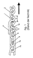
- FIG. 1 It can be seen that the fabric of a known endless screen of longitudinal threads 2 and transverse threads 6 is made. Seam loops are provided at the end of the fabric for attachment of a suture spiral 7a, which are produced by weaving back a section 1a of the longitudinal thread 1 into the fabric in accordance with the binding. In order to facilitate or facilitate this backward weaving, an adjacent longitudinal thread 2 has been removed from the fabric along a section 4. At the other end of the fabric band, another suture spiral 7b is attached in a similar or similar manner. The spirals 7a and 7b which are of oval design in the present embodiment can be pushed into one another laterally and are replaced by a single or multiple elements which can be inserted parallel to the end of the fabric (see FIG FIG. 2 ) Plug wires 9 held together.
- the end of the backwoven portion 1a of the longitudinal thread 1 protrudes in the embodiment shown by a transverse thread 6 further into the tissue than the section 4 of the longitudinal thread 2 is removed from the fabric so that at their overlap region 3, a so-called overlay is formed, which is a better Halt the back-woven portion 1 a in the fabric structure causes.
- a holding wire 8 running essentially parallel to the single or multiple plug wire 9 is additionally provided in each case in the exemplary embodiment shown.
- the section 4 of the longitudinal thread is not cut off at the point where it leaves the fabric in the shown prior art, but is placed over the suture spirals 7a, 7b, to serve as a seam protection, the end of the section 4 against the Direction indicated by an arrow direction of the endless screen is directed so that no further attachment of the sections 4 is required.
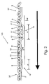
- FIG. 2 and 3 can be seen, thereby form the removed portions 4 ', 4 "of the threads 2', Y 'only in a region in front of the connecting device 7a', 7b 'a support 10', 10".
- the fabric tape device 100 runs over a work surface AF, for example, vacuum zone cover on a chemical washer, Seihzonentischabdeckung, etc.
- a work surface AF for example, vacuum zone cover on a chemical washer, Seihzonentischabdeckung, etc.
- the formation of supports 10 ', 10 "results in an exemption FR of the connection devices 7a', 7b 'of the work surface AF, the connection devices 7a ', 7b' are therefore not on the work surface AF and can therefore not be damaged by this.
- the removed longitudinal threads 2 " which form a bearing surface 10" can only be cut off in front of the corresponding connecting device 7b 'adjoining the fabric band 20 ", so that a support 10" can easily be produced.
- the direction of the fabric tape must be chosen so that the open ends of the support are facing away from the direction of movement, so that the threads are not bent and so the support is damaged.
- the correspondingly correctly selected direction of movement is in the Figures 2 and 3 indicated by an arrow.
- a support 10 ' Much more stable and additionally independent of the direction of the fabric tape device is a support 10 ', if as FIG. 2 and 3 further, removed sections 4 'of longitudinal threads 2' are woven around transverse threads 11 'and are backwoven with them. This results in a stable and relatively thick support surface 10 '.
- the longitudinal threads 2' are backwoven with the fabric tape.
- the transverse threads 11 ' are in this case also advantageously arranged on the underside of the fabric band in the area in front of the connection device 7a' in the area provided in front of the connection device 7a ', so that a comparatively high support surface 10' results.
- transverse thread 12 ' closest to the connecting device 7a', but as a rule a plurality of transverse threads 11 ', are interwoven with the fabric tape.
- the longitudinal threads 2 ' have different dimensions with regard to their removed length 4', for example by the longitudinal threads being removed from the fabric band at different locations relative to the longitudinal direction of the fabric band, so that an overly abrupt transition from the fabric band is avoided Fabric tape to the support surface 10 'results.
- the support surfaces 10 'serving as seam protection and formed by the removed longitudinal threads can also be arranged above the fabric or on both sides of the fabric. It is also possible that the removed longitudinal threads are not distributed uniformly over the width of the fabric tape, but are assigned only to the lateral edge of the fabric tape to form a wear protection for this lateral edge region.
- the Verschndschutz can also be provided only at the high stress points of the fabric connection.
- the sections 4 "of the longitudinal threads 2" removed from the fabric are cut off in front of the connection device 7b', so that on the one hand they also form a support surface 10 "for protecting the connection device, but on the other hand Due to the length of the removed sections of the threads, it is also not possible for them to get caught in the connecting device. Due to the direction of movement (see arrow), weaving back of the threads 4 "is not absolutely necessary.
- a corresponding support surface is formed on the end of the endless sieve associated with the suture spiral 7b 'as at the end of the suture spiral 7a', resulting in an even better support and a even better protection of the connection devices 7a ', 7b' results, but it can also be provided - as is also covered by the presently claimed protection claims - that a support is provided only in an area in front of a connection device 7a ', 7b' that Thus, only one of the supports 10 ', 10 "is present, if this is designed so as to provide sufficient protection for the connection devices 7a', 7b '.
- the length of the region of the support surface 10 ' may be sized differently depending on the application, typical values are approximately 20 cm. A particularly good protection results if the supporting surface 10 'is brought up to the connecting device 7a', but in principle it can also end at a distance in front of the connecting device 7a '.
Landscapes
- Woven Fabrics (AREA)
- Paper (AREA)
Description
- Die Erfindung betrifft eine Gewebeband-Einrichtung, z.B. Endlos-Siebband für Papier- und Zellstoffmaschinen, bei welcher an zumindest einem Ende des Gewebebandes eine Anschlussvorrichtung vorgesehen ist, welche über ein lösbares Verbindungsmittel mit einer weiteren Anschlussvorrichtung desselben oder eines anderen verbindbar ist, wobei eine Anzahl bestimmter Längsfäden entlang eines dem Ende des Gewebebandes zugeordneten Abschnittes aus dem Gewebe herausgenommen ist, wobei die herausgenommenen Abschnitte der Längsfäden an zumindest einer Seite des Gewebebandes in einem Bereich vor der Anschlussvorrichtung aufliegend angeordnet sind, sodass diese eine Abstützung zum Schutz der Anschlussvorrichtungen bei über eine Arbeitsfläche laufendem Gewebeband bilden.
- Lösbare Verbindungen zwischen den zwei stirnseitigen Enden eines Gewebebandes oder zwischen den Enden zweier verschiedener Gewebebänder, wie z.B. Fördergurten, Endlossiebbänder od. dgl., sind bekannt und werden beispielsweise in der
DE 28 10 72 C , derDE 2 059 021 A , derDE 2 338 263 A , derFR 2 145 365 A EP 564 436 A - Bei vielen der bekannten Gewebeverbindungen sind die Anschlussvorrichtungen jedoch einem Verschleiß ausgesetzt, welcher die Lebensdauer des Gurtes beeinträchtigen kann, insbesondere wenn die Gewebeverbindung starken mechanischen Belastungen oder einer erhöhten Verschmutzung ausgesetzt ist. Zum Schutz einer lösbaren Verbindung der oben genannten Art ist in der
FR 2 145 365 A - In der
AT 402 516 - Nachteilig an dieser Einrichtung ist, dass bei einer Verwendung der Gewebeband-Einrichtung unter gewissen Bedingungen die Situation auftritt, dass einer oder mehrere der Längsfäden von dem Gewebeband abgehoben und verbogen werden. Dabei kann es dann vorkommen, dass die Fäden in die Anschlussvorrichtung einfädeln und diese dadurch beschädigt wird.
- Ein Nahtschutz für Papiermaschinesiebe ist aus der
DE 536 605 bekannt. Bei diesem Nahtschutz weist das Sieb an seiner Unterseite eine rampenförmige Erhebung auf, die beispielsweise durch gekröpfte Kettfäden gebildet ist. - Nachteilig an dieser Ausgestaltung eines Papiermaschinensiebes ist allerdings, dass dieser Nahtschutz relativ leicht beschädigt werden kann, indem beispielsweise die Fäden aus dem Gewebe heraus abgehoben bzw. herausgezogen werden.
- Es ist eine Aufgabe der Erfindung, eine Gewebeband-Einrichtung zu schaffen, bei der die oben genannten Probleme nicht auftreten, die aber trotzdem einen guten Schutz für die Anschlussvorrichtung bietet, und die insbesondere einen stabile Schutz der Anschlussvorrichtung liefert.
- Diese Aufgabe wird mit einer eingangs erwähnten Gewebeband-Einrichtung dadurch gelöst, dass erfindungsgemäß die herausgenommenen Abschnitte der Längsfäden um Querfäden herumgewebt und mit diesen rückverwoben sind.
- Auf diese Weise wird eine Art "Verdickung" im Bereich vor zumindest einer Anschlussvorrichtung erreicht, die verhindert, dass die Anschlussvorrichtung bei einem über eine Arbeitsfläche laufenden Gewebeband mit der Arbeitsfläche in Berührung kommt und somit nicht beschädigt werden kann.
- Die herausgenommenen Fäden bilden dabei diese Abstützung - die Fäden begrenzen dabei in der Regel eine fiktive "Abstützfläche", sodass in der folgenden Beschreibung auch von "Abstützfläche" synonym für Abstützung die Rede ist - in einem "Bereich" vor zumindest einer Anschlussvorrichtung, wobei sie natürlich auch in beiden Bereichen eine Verdickung bilden können. Besonders zweckmäßig ist es dabei aber, wenn die herausgenommenen Abschnitte der Längsfäden die Anschlussvorrichtung nicht überlappen, d.h. also nicht in den Bereich der Anschlussvorrichtung reichen. Indem die Fäden nicht über die Anschlussvorrichtung hinaus reichen, können diese auch nicht in die Anschlussvorrichtung hinein gebogen werden und können so diese auch nicht beschädigen.
- Besonders stabil lässt sich die Abstützfläche dadurch gestalten dass erfindungsgemäß die herausgenommenen Abschnitte der Längsfäden um Querfäden herumgewebt und mit diesen rückverwoben sind.
- Es kann vorgesehen sein, dass der Bereich der Abstützfläche bis unmittelbar an die Anschlussvorrichtung reicht, er kann aber auch in einem Abstand vor der Anschlussvorrichtung enden. Die Erstreckung des Bereiches hängt dabei von der zu erwartenden Belastung im Einsatz, vom Einsatzzweck, der Arbeitsfläche etc. ab, und auch von der Dicke der Aufstützfläche. In der Regel wird es aber günstig sein, die Abstützfläche bis möglichst nahe an die Anschlussvorrichtung zu führen, damit ein optimaler Schutz gewährleistet ist, ohne jedoch die Laufeigenschaften des Gewebebandes über die Arbeitsfläche zu beeinträchtigen.
- Weiters lässt sich die Stabilität der Gewebeband-Einrichtung und somit auch deren Lebensdauer dadurch erhöhen, dass in einem Gewebebandbereich anschließend an den Bereich mit Querfäden und sich in eine Richtung weg von der Anschlussvorrichtung erstreckend die Längsfäden mit dem Gewebeband rückverwoben sind.
- Einfach in der Herstellung ist es, wenn die Querfäden an einer der Arbeitsfläche zugewandten Seite des Gewebebandes in dem Bereich vor der Abstützfläche angeordnet sind. Auf diese Weise, insbesondere wenn die Querfäden zwei- oder mehrlagig angeordnet sind, lässt sich auch die Dicke der Abstützfläche erhöhen.
- Besonders gut ist die Abstützfläche mit dem Gewebeband verbunden, wenn zumindest der der Anschlussvorrichtung nächstgelegene Querfaden mit dem Gewebeband verwoben ist. Bei einer konkreten Ausführungsform der Erfindung weisen die Längsfäden hinsichtlich ihrer herausgenommenen Länge unterschiedliche Abmessungen auf. Dies wird beispielsweise dadurch erreicht, dass die Längsfäden an - bezogen auf die Längsrichtung des Gewebebandes - unterschiedlichen Stellen aus dem Gewebeband herausgenommen sind. Mit dieser Anordnung wird erreicht, dass der "Übergang" von dem Gewebeband zu der Abstützfläche nicht abrupt sondern verlaufend über die Breite der Gewebeband-Einrichtung erfolgt, sodass die Einrichtung wesentlich gleichförmiger über die Arbeitsfläche laufen kann.
- Außerdem kann vorgesehen sein, dass die Anzahl herausgenommener Längsfäden nur dem seitlichen Randbereich des Gewebebandes zugeordnet ist. Mit dieser Maßnahme kann zusätzlich erreicht werden, dass ein wirksamer Schutz des im allgemeinen besonders verschleißanfälligen Randbereichs einer Verbindung erreicht wird.
- Ein besonders guter Schutz lässt sich erreichen, wenn die Anzahl herausgenommener Längsfäden gleichmäßig über die gesamte Breite des Gewebebandes verteilt ist.
- Bei einem Gewebe, welches aus Kunststofffäden hergestellt ist, hat es sich als vorteilhaft erwiesen, wenn die herausgenommenen Abschnitte der Längsfäden des Gewebes durch Erhitzen unter Längsspannung thermisch geglättet sind, da die Längsfäden normalerweise gemäß der Gewebestruktur gebogen sind.
- Eine besonders vorteilhafte Ausführungsform ergibt sich, wenn die Anschlussvorrichtung eine an dem Ende des Gewebebandes verlaufende Nahtschlaufenreihe oder eine an diesem Ende befestigte Nahtspirale einer Stecknaht ist und wenn das Verbindungsmittel ein zwei Nahtschlaufen oder Nahtspirale verbindender Nahtverbindungssteckdraht einer Stecknaht ist. Bei dieser Ausführungsform werden die Nahtschlaufenreihen oder die Befestigung der Nahtspirale an dem Ende des Gewebebandes durch bestimmte, abschnittsweise herausgenommene Längsfäden und durch abschnittsweise bindungskonform in das Gewebe zurückgewebte benachbarte Längsfäden gebildet, wobei erfindungsgemäß Längsfäden nur an jenen Stellen aus dem Gewebe herausgenommen sind, an welchen die benachbarten Längsfäden in das Gewebe zurückgewebt sind und die Abschnitte der herausgenommenen Längsfäden die Schutzauflage bilden. Bei dieser Ausführungsform wird eine besondere Verbindungstechnik ausgenützt, um die Abstützfläche herzustellen. Falls die Anschlussvorrichtungen nämlich Nahtschlaufenreihen oder durch Nahtschlaufen an dem Gewebe befestigte Nahtspiralen sind, erfolgt die Herstellung der Nahtschlaufen üblicherweise so, dass bestimmte Längsfäden entlang eines Abschnittes aus dem Gewebe herausgenommen werden, um benachbarte Längsfäden unter Bildung je einer Nahtschlaufe bindungskonform in das Gewebe zurückweben zu können, wobei die herausgenommenen Längsfäden üblicherweise an der Stelle abgeschnitten werden, an der sie das Gewebe verlassen. Bei der erfindungsgemäßen Gewebeband-Einrichtung hingegen bilden die herausgenommenen Fäden die Abstützfläche vor der Anschlussvorrichtung, und müssen nicht an der Stelle, an der sie aus dem Gewebe herausgenommen sind, abgeschnitten werden.
- Weitere Vorteile und Merkmale einer Gewebeband-Einrichtung der erfindungsgemäßen Art ergeben sich aus der folgenden Beschreibung eines erfindungsgemäßen Ausführungsbeispiels, wobei auf die beiliegende Zeichnung Bezug genommen wird. In dieser zeigt
-
Fig.1 eine schematische Seitenansicht einer Gewebeband-Einrichtung im Bereich der lösbaren Verbindung am Beispiel eines Endlos-Siebes für Papier- bzw. Zellstoffmaschinen nach dem bekannten Stand der Technik, -
Fig. 2 eine Gewebeband- Einrichtung mit erfindungsgemäßen Abstützungen, und -
Fig. 3 eine erfindungsgemäße Gewebeband-Einrichtung in einer perspektivischen Draufsicht auf eine Seite mit Abstützungen. -
Figur 1 ist zu entnehmen, dass das Gewebe eines bekannten Endlos-Siebes aus Längsfäden 2 und Querfäden 6 hergestellt ist. An dem Ende des Gewebes sind zur Befestigung einer Nahtspirale 7a Nahtschlaufen vorgesehen, die durch bindungskonformes Zurückweben eines Abschnittes 1a des Längsfadens 1 in das Gewebe hergestellt werden. Um dieses Zurückweben zu ermöglichen bzw. zu erleichtern, ist ein benachbarter Längsfaden 2 entlang eines Abschnittes 4 aus dem Gewebe entnommen. An dem anderen Ende des Gewebebandes ist in ähnlicher oder gleicher Weise eine weitere Nahtspirale 7b befestigt. Die bei der vorliegenden Ausführungsform oval ausgebildeten Spiralen 7a und 7b sind seitlich ineinanderschiebbar und werden durch einen gerade parallel zum Gewebeende einschiebbare ein- oder mehrfache (sieheFigur 2 ) Steckdrähte 9 aneinander gehalten. - Das Ende des zurückgewebten Abschnittes 1a des Längsfadens 1 ragt bei dem gezeigten Ausführungsbeispiel um einen Querfaden 6 weiter in das Gewebe hinein als der Abschnitt 4 des Längsfadens 2 aus dem Gewebe entnommen ist, sodass an deren Überschneidungsbereich 3 ein sogenannter Überleger gebildet wird, welcher einen besseren Halt des zurückgewebten Abschnittes 1a in der Gewebestruktur bewirkt. In der Verbindungszone zwischen den Nahtschlaufen und den Nahtspiralen 7a, 7b ist bei dem gezeigten Ausführungsbeispiel zusätzlich je ein im wesentlichen parallel zum ein- oder mehrfachen Steckdraht 9 verlaufender Haltedraht 8 vorgesehen.
- Der Abschnitt 4 des Längsfadens wird bei dem gezeigten Stand der Technik nicht an der Stelle abgeschnitten, wo er das Gewebe verlässt, sondern wird über die Nahtspiralen 7a, 7b gelegt, um dort als ein Nahtschutz zu dienen, wobei das Ende des Abschnittes 4 gegen die mit einem Pfeil gekennzeichnete Laufrichtung des Endlos-Siebes gerichtet ist, sodass keine weitere Befestigung der Abschnitte 4 erforderlich ist.
- Wie eingangs erwähnt, weist diese Anordnung allerdings den Nachteil auf, dass unter gewissen Bedingungen Längsfäden 4 von dem Gewebeband abgehoben werden und sich in den Anschlussvorrichtungen 7a, 7b verfangen und diese beschädigen oder zerstören können.
- Dies kann mit einer erfindungsgemäßen, in den
Figuren 2 und3 dargestellten Gewebeband-Einrichtung vermieden werden. Das in derFigur 2 gezeigte Gewebeband 20', 20" weist dabei die erfindungsgemäßen Abstützungen 10', 10" , wie noch ausgeführt, an der Unterseite (das ist in der Regel die einer Arbeitsfläche zugewandte Seite) auf, während das Gewebeband nachFigur 3 diese zur besseren Darstellung an einer in der Zeichnung obenliegenden Seite aufweist. - Wie
Figur 2 und3 zu entnehmen ist, bilden dabei die entnommenen Abschnitte 4', 4" der Fäden 2', Y' lediglich in einem Bereich vor der Anschlussvorrichtung 7a', 7b' eine Abstützung 10', 10". Dadurch, dass die Abstützung 10', 10'; - im folgenden auch Abstützfläche oder Abstützbereich genannt - unmittelbar oder in einem gewissen Abstand vor der Anschlussvorrichtung 7a', 7b' endet, ist auch die Gefahr vermieden, dass sich einer der die Abstützfläche 10',10" bildenden Fäden in der Anschlussvorrichtung 7a', 7b' verfangen. - Gemäß der Darstellung nach
Figur 2 läuft dabei die Gewebeband-Einrichtung 100 über eine Arbeitsfläche AF, beispielsweise Vakuumzonenabdeckung auf einem Chemi Washer, Seihzonentischabdeckung, etc. Durch die Ausbildung von Abstützungen 10', 10" ergibt sich eine Freistellung FR der Anschlussvorrichtungen 7a', 7b' von der Arbeitsfläche AF, die Anschlussvorrichtungen 7a', 7b' liegen also nicht auf der Arbeitsfläche AF auf und können demgemäss auch von dieser nicht beschädigt werden. - Grundsätzlich können die herausgenommenen Längsfäden 2", welche eine Auflagefläche 10" bilden, lediglich vor der entsprechenden, an das Gewebeband 20" anschließenden Anschlussvorrichtung 7b' abgeschnitten sein. Damit lässt sich einfach eine Abstützung 10" herstellen. Allerdings muss dann die Laufrichtung des Gewebebandes so gewählt werden, dass die offenen Enden der Abstützung von der Bewegungsrichtung abgewandt sind, damit nicht die Fäden aufgebogen und so die Abstützung beschädigt wird. Die entsprechend richtig gewählte Bewegungsrichtung ist in den
Figuren 2 und3 durch einen Pfeil gekennzeichnet. - Wesentlich stabiler und zusätzlich von der Laufrichtung der Gewebeband-Einrichtung unabhängig ist eine Abstützung 10', wenn wie
Figur 2 und3 weiters zu entnehmen, herausgenommene Abschnitte 4' von Längsfäden 2' um Querfäden 11' herumgewebt und mit diesen rückverwoben sind. Dadurch ergibt sich eine stabile und relativ dicke Abstützfläche 10'. Außerdem sind anschließend an den Bereich mit Querfäden 11' die Längsfäden 2' mit dem Gewebeband rückverwoben. Die Querfäden 11' sind dabei bei einer an der Unterseite der Gewebeband-Einrichtung vorgesehenen Abstützfläche 10' vorteilhafterweise ebenfalls an der Unterseite des Gewebebandes in dem Bereich vor der Anschlussvorrichtung 7a' angeordnet, sodass sich eine vergleichsweise hohe Abstützfläche 10' ergibt. - Hinsichtlich der Stabilität ist es weiters vorteilhaft, wenn zumindest der der Anschlussvorrichtung 7a' nächstgelegene Querfaden 12', in der Regel aber mehrere Querfäden 11', mit dem Gewebeband verwoben sind.
- Ebenso ist es günstig, wenn die Längsfäden 2' hinsichtlich ihrer herausgenommenen Länge 4' unterschiedliche Abmessungen aufweisen, beispielsweise indem die Längsfäden an - bezogen auf die Längsrichtung des Gewebebandes - unterschiedlichen Stellen aus dem Gewebeband herausgenommen sind, sodass sich nicht ein allzu abrupter Übergang von dem Gewebeband zu der Abstützfläche 10' ergibt.
- Die als Nahtschutz dienenden, von den herausgenommenen Längsfäden gebildeten Abstützflächen 10' können auch oberhalb des Gewebes oder zu beiden Seiten des Gewebes angeordnet sein. Ebenso ist es möglich, dass die herausgenommenen Längsfäden nicht gleichmäßig über die Breite des Gewebebandes verteilt sind, sondern nur dem seitlichen Rand des Gewebebandes zugeordnet sind, um einen Verschleißschutz für diesen seitlichen Randbereich zu bilden.
- Falls das Gewebeband, z.B. durch eine besondere Formgebung der Walzen, unterschiedlich beansprucht wird, kann der Verscheißschutz auch lediglich an den stark beanspruchten Stellen der Gewebeverbindung vorgesehen sein.
- An dem der Nahtspirale 7b' zugeordneten anderen Ende des Endlos-Siebes werden die aus dem Gewebe entnommenen Abschnitte 4" der Längsfäden 2" vor der Anschlussvorrichtung 7b' abgeschnitten, sodass sie einerseits ebenfalls eine Abstützfläche 10" zum Schutz der Anschlussvorrichtung bilden, andererseits es aber aufgrund der Länge der herausgenommenen Abschnitte der Fäden auch nicht möglich ist, dass sich diese in der Anschlussvorrichtung verfangen. Aufgrund der Bewegungsrichtung (siehe Pfeil) ist ein Rückweben der Fäden 4" nicht unbedingt notwendig.
- Grundsätzlich kann aber natürlich auch vorgesehen sein, dass auch auf dem der Nahtspirale 7b' zugeordneten Ende des Endlos-Siebes eine entsprechende Abstützfläche wie an dem Ende der Nahtspirale 7a' gebildete ist, wodurch sich eine noch bessere Abstützung und eine noch besserer Schutz der Anschlussvorrichtungen 7a', 7b' ergibt, es kann aber auch vorgesehen sein - wie dies auch von dem vorliegend beanspruchten Schutzbegehren mit umfasst ist - dass eine Abstützung nur in einem Bereich vor einer Anschlussvorrichtung 7a', 7b' vorgesehen ist, dass also nur eine der Abstützungen 10', 10" vorhanden ist, wenn diese derart ausgebildet ist, um ausreichenden Schutz für die Anschlussvorrichtungen 7a', 7b' zu bieten.
- Sowohl das Gewebe 20' als auch die Nahtspiralen 7a', 7b' und der Steckdraht 8', 9, die Querfäden 11', 12', und die herausgenommenen Längsfäden 2', 2" sind bei dem gezeigten Ausführungsbeispiel aus einem Kunststoff hergestellt. Da die Abschnitte 4', 4" der Längsfäden 2', 2" nach ihrem Herausnehmen sogenannten Crimps aufweisen, d.h. entsprechend der Gewebestruktur schlangenförmig gebogen sind, werden diese beim Thermofixieren der Nahtschlaufen durch Erhitzen unter Längsspannung glattgezogen.
- Die Länge des Bereiches der Abstützfläche 10' kann je nach Anwendungsfall unterschiedlich bemessen sein, typische Werte liegen in etwa bei 20 cm. Ein besonders guter Schutz ergibt sich, wenn dabei die Abstützfläche 10' bis unmittelbar bis an die Anschlussvorrichtung 7a' herangeführt ist, grundsätzlich kann diese aber auch in einem Abstand vor der Anschlussvorrichtung 7a' enden.
Claims (16)
- Gewebeband-Einrichtung, z.B. Endlos-Siebband für Papier- und Zellstoffmaschinen, bei welcher an zumindest einem Ende des Gewebebandes (20', 20") eine Anschlussvorrichtung (7a'; 7b') vorgesehen ist, welche über ein lösbares Verbindungsmittel (9) mit einer weiteren Anschlussvorrichtung (7b'; 7a') desselben oder eines anderen Gewebebandes verbindbar ist, wobei eine Anzahl bestimmter Längsfäden (2', 2") entlang eines dem Ende des Gewebebandes zugeordneten Abschnittes (4', 4") aus dem Gewebe (20') herausgenommen ist, wobei die herausgenommenen Abschnitte (4', 4") der Längsfäden (2', 2") an zumindest einer Seite des Gewebebandes (20', 20") in einem Bereich vor der Abschlussvorrichtung (7a'; n7b') aufliegend angeordnet sind, sodass diese eine Abstützung (10'; 10") zum Schutz der Anschlussvorrichtungen (7a'; 7b') bei über eine Arbeitsfläche (AF) laufendem Gewebeband bilden, dadurch gekennzeichnet, dass die herausgenommenen Abschnitte (4') der Längsfäden (2') um Querfäden (11', 12') herumgewebt und mit diesen rückverwoben sind.
- Gewebeband-Einrichtung nach Anspruch 1, dadurch gekennzeichnet, dass die herausgenommenen Abschnitte (4', 4") der Längsfäden (2'; 2") die Anschlussvorrichtung (7a', 7b') nicht überlappen.
- Gewebeband-Einrichtung nach Anspruch 1 oder 2, dadurch gekennzeichnet, dass der Bereich der Abstützung (10', 10") bis unmittelbar an die Anschlussvorrichtung (7a'; 7b') reicht.
- Gewebeband-Einrichtung nach Anspruch 1 oder 2, dadurch gekennzeichnet, dass der Bereich der Abstützfläche (10', 10") in einem Abstand vor der Anschlussvorrichtung (7a'; 7b') endet.
- Gewebeband-Einrichtung nach einem der Ansprüche 1 bis 4, dadurch gekennzeichnet, dass in einem Gewebebandbereich anschließend an den Bereich mit Querfäden (11',12') und sich in eine Richtung weg von der Anschlussvornchtung (7a') erstreckend die Längsfäden (2') mit dem Gewebeband rückverwoben sind.
- Gewebeband-Einrichtung nach einem der Ansprüche 1 bis 5, dadurch gekennzeichnet, dass die Querfäden (11', 12') an einer der Arbeitsfläche (AF) zugewandten Seite des Gewebebandes in Bewegungsrichtung gesehen in einem Bereich vor der Abstützfläche (7a') angeordnet sind.
- Gewebeband-Einrichtung nach einem der Ansprüche 1 bis 6, dadurch gekennzeichnet, dass die Querfäden (11',12') zwei- oder mehrlagig angeordnet sind.
- Gewebeband-Einrichtung nach einem der Ansprüche 1 bis 7, dadurch gekennzeichnet, dass zumindest der der Anschlussvomichtung (7a') nächstgelegene Querfaden (12') mit dem Gewebeband (20') verwoben ist.
- Gewebeband-Einrichtung nach einem der Ansprüche 1 bis 8, dadurch gekennzeichnet, dass die Längsfäden (2', 2") hinsichtlich ihrer herausgenommenen Länge (4', 4") unterschiedliche Abmessungen aufweisen.
- Gewebeband-Einrichtung nach Anspruch 9, dadurch gekennzeichnet, dass die Längsfäden (2', 2") an - bezogen auf die Längsrichtung des Gewebebandes - unterschiedlichen Stellen aus dem Gewebeband (20', 20") herausgenommen sind.
- Gewebeband-Einrichtung nach einem der Ansprüche 1 bis 10, dadurch gekennzeichnet, dass die Anzahl herausgenommener Längsfäden (2', 2") nur dem seitlichen Randbereich des Gewebebandes (20', 20") zugeordnet ist.
- Gewebeband-Einrichtung nach einem der Ansprüche 1 bis 10, dadurch gekennzeichnet, dass die Anzahl herausgenommener Längsfäden (2', 2") gleichmäßig über die gesamte Breite des Gewebebandes (20', 20") verteilt ist.
- Gewebeband-Einrichtung nach einem der Ansprüche 1 bis 12, bei welchem das Gewebe (20', 20") aus Kunststofffäden hergestellt ist, dadurch gekennzeichnet, dass die herausgenommenen Abschnitte (4', 4") der Längsfäden (2', 2") des Gewebes durch Erhitzen unter Längsspannung thermisch geglättet sind.
- Gewebeband-Einrichtung nach einem der Ansprüche 1 bis 13, dadurch gekennzeichnet, dass die Anschlussvorrichtung eine an dem Ende des Gewebebandes verlaufende Nahtschlaufenreihe oder eine an diesem Ende befestigte Nahtspirale (7a', 7b') einer Stecknaht ist.
- Gewebeband-Einrichtung nach Anspruch 14, dadurch gekennzeichnet, dass das Verbindungsmittel ein zwei Nahtschlaufen oder Nahtspirale (7a', 7b') verbindender Nahtverbindungssteckdraht (9') einer Stecknaht ist.
- Gewebeband-Einrichtung nach Anspruch 14 oder 15, bei welchem die Nahtschlaufenreihe oder die Befestigung der Nahtspirale (7a', 7b') an dem Ende des Gewebebandes durch bestimmte, abschnittsweise herausgenommenen Längsfäden (2', 2") und durch abschnittsweise bindungskonform in das Gewebe (20', 20") zurückgewebte benachbarte Längsfäden gebildet ist, dadurch gekennzeichnet, dass Längsfäden (2', 2") nur an jenen Stellen aus dem Gewebe herausgenommen sind, an welchen die benachbarten Längsfäden in das Gewebe zurückgewebt sind.
Priority Applications (2)
| Application Number | Priority Date | Filing Date | Title |
|---|---|---|---|
| SI200331645T SI1525352T1 (sl) | 2002-07-05 | 2003-05-28 | Naprava, katere osnova je tkan pas |
| AT03726997T ATE431870T1 (de) | 2002-07-05 | 2003-05-28 | Gewebeband-einrichtung |
Applications Claiming Priority (3)
| Application Number | Priority Date | Filing Date | Title |
|---|---|---|---|
| AT10102002 | 2002-07-05 | ||
| AT0101002A AT411605B (de) | 2002-07-05 | 2002-07-05 | Gewebeband-einrichtung |
| PCT/AT2003/000159 WO2004005612A1 (de) | 2002-07-05 | 2003-05-28 | Gewebeband-einrichtung |
Publications (2)
| Publication Number | Publication Date |
|---|---|
| EP1525352A1 EP1525352A1 (de) | 2005-04-27 |
| EP1525352B1 true EP1525352B1 (de) | 2009-05-20 |
Family
ID=27625625
Family Applications (1)
| Application Number | Title | Priority Date | Filing Date |
|---|---|---|---|
| EP03726997A Expired - Lifetime EP1525352B1 (de) | 2002-07-05 | 2003-05-28 | Gewebeband-einrichtung |
Country Status (11)
| Country | Link |
|---|---|
| US (1) | US7036533B2 (de) |
| EP (1) | EP1525352B1 (de) |
| AT (2) | AT411605B (de) |
| AU (1) | AU2003232915B2 (de) |
| CA (1) | CA2491517C (de) |
| DE (1) | DE50311534D1 (de) |
| NZ (1) | NZ538018A (de) |
| PT (1) | PT1525352E (de) |
| RU (1) | RU2301857C2 (de) |
| SI (1) | SI1525352T1 (de) |
| WO (1) | WO2004005612A1 (de) |
Families Citing this family (34)
| Publication number | Priority date | Publication date | Assignee | Title |
|---|---|---|---|---|
| EP1808527A1 (de) * | 2006-01-17 | 2007-07-18 | Voith Patent GmbH | Nassfilz mit Naht und Verfahren zu dessen Herstellung |
| US7360560B2 (en) * | 2006-01-31 | 2008-04-22 | Astenjohnson, Inc. | Single layer papermakers fabric |
| US10632740B2 (en) | 2010-04-23 | 2020-04-28 | Landa Corporation Ltd. | Digital printing process |
| US9498946B2 (en) | 2012-03-05 | 2016-11-22 | Landa Corporation Ltd. | Apparatus and method for control or monitoring of a printing system |
| US9902147B2 (en) | 2012-03-05 | 2018-02-27 | Landa Corporation Ltd. | Digital printing system |
| KR102066303B1 (ko) | 2012-03-05 | 2020-01-14 | 란다 코퍼레이션 리미티드 | 잉크막 구조 |
| US9643403B2 (en) | 2012-03-05 | 2017-05-09 | Landa Corporation Ltd. | Printing system |
| WO2013132418A2 (en) | 2012-03-05 | 2013-09-12 | Landa Corporation Limited | Digital printing process |
| HK1204640A1 (en) | 2012-03-05 | 2015-11-27 | Landa Corporation Ltd. | Ink film constructions |
| US10434761B2 (en) | 2012-03-05 | 2019-10-08 | Landa Corporation Ltd. | Digital printing process |
| US10642198B2 (en) | 2012-03-05 | 2020-05-05 | Landa Corporation Ltd. | Intermediate transfer members for use with indirect printing systems and protonatable intermediate transfer members for use with indirect printing systems |
| CN104284850B (zh) | 2012-03-15 | 2018-09-11 | 兰达公司 | 打印系统的环形柔性皮带 |
| GB201401173D0 (en) | 2013-09-11 | 2014-03-12 | Landa Corp Ltd | Ink formulations and film constructions thereof |
| GB2536489B (en) | 2015-03-20 | 2018-08-29 | Landa Corporation Ltd | Indirect printing system |
| GB2537813A (en) | 2015-04-14 | 2016-11-02 | Landa Corp Ltd | Apparatus for threading an intermediate transfer member of a printing system |
| US10933661B2 (en) | 2016-05-30 | 2021-03-02 | Landa Corporation Ltd. | Digital printing process |
| GB201609463D0 (en) | 2016-05-30 | 2016-07-13 | Landa Labs 2012 Ltd | Method of manufacturing a multi-layer article |
| WO2019077489A1 (en) | 2017-10-19 | 2019-04-25 | Landa Corporation Ltd. | FLEXIBLE BELT WITHOUT END FOR A PRINTING SYSTEM |
| US11267239B2 (en) | 2017-11-19 | 2022-03-08 | Landa Corporation Ltd. | Digital printing system |
| WO2019102297A1 (en) | 2017-11-27 | 2019-05-31 | Landa Corporation Ltd. | Digital printing system |
| US11707943B2 (en) | 2017-12-06 | 2023-07-25 | Landa Corporation Ltd. | Method and apparatus for digital printing |
| WO2019111223A1 (en) | 2017-12-07 | 2019-06-13 | Landa Corporation Ltd. | Digital printing process and method |
| IL279556B2 (en) | 2018-06-26 | 2024-06-01 | Landa Corp Ltd | Part for intermediate transfer to a digital printing system |
| US10994528B1 (en) | 2018-08-02 | 2021-05-04 | Landa Corporation Ltd. | Digital printing system with flexible intermediate transfer member |
| WO2020035766A1 (en) | 2018-08-13 | 2020-02-20 | Landa Corporation Ltd. | Correcting distortions in digital printing by implanting dummy pixels in a digital image |
| JP7246496B2 (ja) | 2018-10-08 | 2023-03-27 | ランダ コーポレイション リミテッド | 印刷システムおよび方法に関する摩擦低減手段 |
| JP7462648B2 (ja) | 2018-12-24 | 2024-04-05 | ランダ コーポレイション リミテッド | デジタル印刷システム |
| EP3946953A4 (de) | 2019-03-31 | 2022-12-14 | Landa Corporation Ltd. | Systeme und verfahren zur verhinderung oder minimierung von druckdefekten in druckverfahren |
| WO2021105806A1 (en) | 2019-11-25 | 2021-06-03 | Landa Corporation Ltd. | Drying ink in digital printing using infrared radiation absorbed by particles embedded inside itm |
| US11321028B2 (en) | 2019-12-11 | 2022-05-03 | Landa Corporation Ltd. | Correcting registration errors in digital printing |
| US12011920B2 (en) | 2019-12-29 | 2024-06-18 | Landa Corporation Ltd. | Printing method and system |
| CN116848473A (zh) | 2021-02-02 | 2023-10-03 | 兰达公司 | 减轻印刷图像中的失真 |
| CN113265746A (zh) * | 2021-04-12 | 2021-08-17 | 信泰(福建)科技有限公司 | 一种绞棕弹性立体织物及其制作工艺 |
| CN113768254B (zh) * | 2021-09-27 | 2023-04-14 | 福建浔兴拉链科技股份有限公司 | 拉链带、拉链、应用拉链的物品及拉链带织造方法 |
Family Cites Families (23)
| Publication number | Priority date | Publication date | Assignee | Title |
|---|---|---|---|---|
| DE536605C (de) * | 1931-10-24 | Rudolph Oschatz | Nahtschutz fuer Papiermaschinensiebe | |
| SU61011A1 (ru) * | 1939-09-25 | 1941-11-30 | Ш.А. Блехман | Способ сращивани многослойных сукон дл бумагоделательных машин |
| GB1149678A (en) * | 1967-05-23 | 1969-04-23 | Fabric Res Lab Inc | Hand laced seams |
| GB1488815A (en) * | 1974-09-27 | 1977-10-12 | Scapa Porritt Ltd | Providing loops at a fabric end |
| US4103717A (en) * | 1976-06-18 | 1978-08-01 | William Kenyon & Sons, Inc. | Seam webbing |
| DE2731754C2 (de) * | 1977-07-14 | 1982-08-26 | Fertex Textilmaschinen-Service GmbH, 6072 Dreieich | Verbindngsnaht für einen aus einem Gewebe bestehenden Trockenfilz oder -sieb für Papiermaschinen |
| US4438788A (en) * | 1980-09-30 | 1984-03-27 | Scapa Inc. | Papermakers belt formed from warp yarns of non-circular cross section |
| DE3147115A1 (de) * | 1981-11-27 | 1983-06-01 | Hermann Wangner Gmbh & Co Kg, 7410 Reutlingen | Spiralgliederband und verfahren zu dessen herstellung |
| SU1461782A1 (ru) * | 1987-03-27 | 1989-02-28 | Ленинградский институт текстильной и легкой промышленности им.С.М.Кирова | Ткана сушильна сетка дл бумагоделательных машин |
| US5411062A (en) * | 1990-06-06 | 1995-05-02 | Asten Group, Inc. | Papermakers fabric with orthogonal machine direction yarn seaming loops |
| US5092373A (en) * | 1990-06-06 | 1992-03-03 | Asten Group, Inc. | Papermakers fabric with orthogonal machine direction yarn seaming loops |
| US5117865A (en) * | 1990-06-06 | 1992-06-02 | Asten Group, Inc. | Papermakers fabric with flat high aspect ratio yarns |
| US5343896A (en) * | 1990-06-06 | 1994-09-06 | Asten Group, Inc. | Papermakers fabric having stacked machine direction yarns |
| USRE35966E (en) * | 1990-06-06 | 1998-11-24 | Asten, Inc. | Papermakers fabric with orthogonal machine direction yarn seaming loops |
| JPH07507605A (ja) * | 1993-03-19 | 1995-08-24 | ジェイダブリューアイ リミテッド カンパニー | 高ループ密度ピンシーム |
| NZ272169A (en) * | 1994-06-09 | 1997-06-24 | Albany Int Corp | Transfer belt for papermaking machine: seam construction: pintles passed through seaming loops |
| US5503196A (en) * | 1994-12-07 | 1996-04-02 | Albany International Corp. | Papermakers fabric having a system of machine-direction yarns residing interior of the fabric surfaces |
| SE504119C2 (sv) * | 1995-03-27 | 1996-11-18 | Nordiskafilt Ab Albany | Maskinbeklädnad med söm samt spiral för användning i en sådan söm |
| AT402516B (de) * | 1995-08-28 | 1997-06-25 | Huyck Austria | Gewebeband-einrichtung |
| US5601120A (en) * | 1996-01-30 | 1997-02-11 | Asten, Inc. | Pin seam with double end loops and method |
| FR2789702B1 (fr) * | 1999-02-16 | 2001-03-30 | Cofpa | Jonction a armure symetrique pour bande tissee a armure asymetrique |
| US6302155B1 (en) * | 2000-07-14 | 2001-10-16 | Albany International Ab | Four-layer seamed press fabric |
| US6491794B2 (en) * | 2001-03-29 | 2002-12-10 | Albany International Corp. | Base structure for seamed papermaker's fabrics |
-
2002
- 2002-07-05 AT AT0101002A patent/AT411605B/de not_active IP Right Cessation
- 2002-07-08 US US10/190,893 patent/US7036533B2/en not_active Expired - Lifetime
-
2003
- 2003-05-28 CA CA002491517A patent/CA2491517C/en not_active Expired - Lifetime
- 2003-05-28 DE DE50311534T patent/DE50311534D1/de not_active Expired - Lifetime
- 2003-05-28 NZ NZ538018A patent/NZ538018A/en not_active IP Right Cessation
- 2003-05-28 SI SI200331645T patent/SI1525352T1/sl unknown
- 2003-05-28 WO PCT/AT2003/000159 patent/WO2004005612A1/de not_active Ceased
- 2003-05-28 AT AT03726997T patent/ATE431870T1/de not_active IP Right Cessation
- 2003-05-28 EP EP03726997A patent/EP1525352B1/de not_active Expired - Lifetime
- 2003-05-28 AU AU2003232915A patent/AU2003232915B2/en not_active Expired
- 2003-05-28 PT PT03726997T patent/PT1525352E/pt unknown
- 2003-05-28 RU RU2005102834/12A patent/RU2301857C2/ru active
Also Published As
| Publication number | Publication date |
|---|---|
| SI1525352T1 (sl) | 2009-12-31 |
| AU2003232915B2 (en) | 2009-01-22 |
| NZ538018A (en) | 2007-03-30 |
| CA2491517C (en) | 2008-10-28 |
| US20040003863A1 (en) | 2004-01-08 |
| EP1525352A1 (de) | 2005-04-27 |
| AU2003232915A1 (en) | 2004-01-23 |
| WO2004005612A1 (de) | 2004-01-15 |
| US7036533B2 (en) | 2006-05-02 |
| CA2491517A1 (en) | 2004-01-15 |
| ATA10102002A (de) | 2003-08-15 |
| DE50311534D1 (de) | 2009-07-02 |
| PT1525352E (pt) | 2009-08-19 |
| AT411605B (de) | 2004-03-25 |
| RU2301857C2 (ru) | 2007-06-27 |
| RU2005102834A (ru) | 2005-11-10 |
| ATE431870T1 (de) | 2009-06-15 |
Similar Documents
| Publication | Publication Date | Title |
|---|---|---|
| EP1525352B1 (de) | Gewebeband-einrichtung | |
| DE2836784C2 (de) | Endlosverbindung für die Enden eines Langsiebes, eines Naßfilzes, eines Trockenfilzes in Papiermaschinen | |
| EP0888478B1 (de) | Verstärkte nahtverbindung für hochzugfeste gewebe | |
| DE3914533C2 (de) | ||
| EP0116916A2 (de) | Rundschlinge, daraus gebildete Stroppe oder daraus gebildete Rundschlingenmatte | |
| CH610273A5 (en) | Flat formation acting as a wire link conveyor | |
| DE19923088C1 (de) | Papiermaschinenbespannung, insbesondere als Trockensieb | |
| DE2856552C2 (de) | Reißverschluß mit einem gewebten Tragband | |
| EP0747303A1 (de) | Stabband für Stabbandförderer | |
| EP0262467A1 (de) | Maschinenbespannung, insbesondere Papiermaschinenfilz oder -sieb | |
| EP0763623B1 (de) | Papiermaschienenband | |
| CH642407A5 (de) | Webelitze. | |
| DE69810508T2 (de) | Veränderte schraubenförmige naht | |
| DE3914534C1 (de) | ||
| DE2455185A1 (de) | Gewebe zur herstellung von papier | |
| AT402516B (de) | Gewebeband-einrichtung | |
| EP1795635B1 (de) | Weblitze für bandförmige Kettfäden | |
| EP1452639A1 (de) | Papiermaschinenbespannung | |
| DE2102478A1 (en) | Wire screen joint - with oblique disposition wrt direction of motion to reduce flapping and starting torque | |
| DE68920197T2 (de) | Endloser Siebgürtel für einen Cellulosebreiverdichter. | |
| CH652692A5 (de) | Kantenschutzeinrichtung an einem gliederriemen. | |
| EP0557478B1 (de) | Verfahren zur vermeidung von laufmaschen an der filterhülle eines drainageelements | |
| DE2243047A1 (de) | Gewebebahn und verfahren zum vorbereiten derselben fuer eine verbindungsstelle | |
| DE1251105B (de) | Endlose Verbindung von Gewebebaendern, insbesondere Trockenfilzen und Trockensieben fuer die Papier- und Zellstoffindustrie | |
| DE10012692B4 (de) | Moppbezug |
Legal Events
| Date | Code | Title | Description |
|---|---|---|---|
| PUAI | Public reference made under article 153(3) epc to a published international application that has entered the european phase |
Free format text: ORIGINAL CODE: 0009012 |
|
| 17P | Request for examination filed |
Effective date: 20050119 |
|
| AK | Designated contracting states |
Kind code of ref document: A1 Designated state(s): AT BE BG CH CY CZ DE DK EE ES FI FR GB GR HU IE IT LI LU MC NL PT RO SE SI SK TR |
|
| AX | Request for extension of the european patent |
Extension state: AL LT LV MK |
|
| DAX | Request for extension of the european patent (deleted) | ||
| 17Q | First examination report despatched |
Effective date: 20070710 |
|
| GRAP | Despatch of communication of intention to grant a patent |
Free format text: ORIGINAL CODE: EPIDOSNIGR1 |
|
| GRAS | Grant fee paid |
Free format text: ORIGINAL CODE: EPIDOSNIGR3 |
|
| GRAA | (expected) grant |
Free format text: ORIGINAL CODE: 0009210 |
|
| AK | Designated contracting states |
Kind code of ref document: B1 Designated state(s): AT BE BG CH CY CZ DE DK EE ES FI FR GB GR HU IE IT LI LU MC NL PT RO SE SI SK TR |
|
| REG | Reference to a national code |
Ref country code: GB Ref legal event code: FG4D Free format text: NOT ENGLISH |
|
| REG | Reference to a national code |
Ref country code: CH Ref legal event code: EP |
|
| REG | Reference to a national code |
Ref country code: IE Ref legal event code: FG4D Free format text: LANGUAGE OF EP DOCUMENT: GERMAN |
|
| REF | Corresponds to: |
Ref document number: 50311534 Country of ref document: DE Date of ref document: 20090702 Kind code of ref document: P |
|
| REG | Reference to a national code |
Ref country code: PT Ref legal event code: SC4A Free format text: AVAILABILITY OF NATIONAL TRANSLATION Effective date: 20090813 |
|
| REG | Reference to a national code |
Ref country code: SE Ref legal event code: TRGR |
|
| PG25 | Lapsed in a contracting state [announced via postgrant information from national office to epo] |
Ref country code: ES Free format text: LAPSE BECAUSE OF FAILURE TO SUBMIT A TRANSLATION OF THE DESCRIPTION OR TO PAY THE FEE WITHIN THE PRESCRIBED TIME-LIMIT Effective date: 20090831 |
|
| NLV1 | Nl: lapsed or annulled due to failure to fulfill the requirements of art. 29p and 29m of the patents act | ||
| BERE | Be: lapsed |
Owner name: HUYCK AUSTRIA GES. M.B.H. Effective date: 20090531 |
|
| PG25 | Lapsed in a contracting state [announced via postgrant information from national office to epo] |
Ref country code: NL Free format text: LAPSE BECAUSE OF FAILURE TO SUBMIT A TRANSLATION OF THE DESCRIPTION OR TO PAY THE FEE WITHIN THE PRESCRIBED TIME-LIMIT Effective date: 20090520 |
|
| REG | Reference to a national code |
Ref country code: IE Ref legal event code: FD4D |
|
| PG25 | Lapsed in a contracting state [announced via postgrant information from national office to epo] |
Ref country code: MC Free format text: LAPSE BECAUSE OF NON-PAYMENT OF DUE FEES Effective date: 20090531 |
|
| REG | Reference to a national code |
Ref country code: CH Ref legal event code: PL |
|
| PG25 | Lapsed in a contracting state [announced via postgrant information from national office to epo] |
Ref country code: EE Free format text: LAPSE BECAUSE OF FAILURE TO SUBMIT A TRANSLATION OF THE DESCRIPTION OR TO PAY THE FEE WITHIN THE PRESCRIBED TIME-LIMIT Effective date: 20090520 Ref country code: CZ Free format text: LAPSE BECAUSE OF FAILURE TO SUBMIT A TRANSLATION OF THE DESCRIPTION OR TO PAY THE FEE WITHIN THE PRESCRIBED TIME-LIMIT Effective date: 20090520 Ref country code: CH Free format text: LAPSE BECAUSE OF NON-PAYMENT OF DUE FEES Effective date: 20090531 Ref country code: LI Free format text: LAPSE BECAUSE OF NON-PAYMENT OF DUE FEES Effective date: 20090531 Ref country code: DK Free format text: LAPSE BECAUSE OF FAILURE TO SUBMIT A TRANSLATION OF THE DESCRIPTION OR TO PAY THE FEE WITHIN THE PRESCRIBED TIME-LIMIT Effective date: 20090520 Ref country code: RO Free format text: LAPSE BECAUSE OF FAILURE TO SUBMIT A TRANSLATION OF THE DESCRIPTION OR TO PAY THE FEE WITHIN THE PRESCRIBED TIME-LIMIT Effective date: 20090520 Ref country code: IE Free format text: LAPSE BECAUSE OF FAILURE TO SUBMIT A TRANSLATION OF THE DESCRIPTION OR TO PAY THE FEE WITHIN THE PRESCRIBED TIME-LIMIT Effective date: 20090520 |
|
| PG25 | Lapsed in a contracting state [announced via postgrant information from national office to epo] |
Ref country code: SK Free format text: LAPSE BECAUSE OF FAILURE TO SUBMIT A TRANSLATION OF THE DESCRIPTION OR TO PAY THE FEE WITHIN THE PRESCRIBED TIME-LIMIT Effective date: 20090520 |
|
| PLBE | No opposition filed within time limit |
Free format text: ORIGINAL CODE: 0009261 |
|
| STAA | Information on the status of an ep patent application or granted ep patent |
Free format text: STATUS: NO OPPOSITION FILED WITHIN TIME LIMIT |
|
| PG25 | Lapsed in a contracting state [announced via postgrant information from national office to epo] |
Ref country code: BG Free format text: LAPSE BECAUSE OF FAILURE TO SUBMIT A TRANSLATION OF THE DESCRIPTION OR TO PAY THE FEE WITHIN THE PRESCRIBED TIME-LIMIT Effective date: 20090820 |
|
| 26N | No opposition filed |
Effective date: 20100223 |
|
| PG25 | Lapsed in a contracting state [announced via postgrant information from national office to epo] |
Ref country code: BE Free format text: LAPSE BECAUSE OF NON-PAYMENT OF DUE FEES Effective date: 20090531 |
|
| PG25 | Lapsed in a contracting state [announced via postgrant information from national office to epo] |
Ref country code: AT Free format text: LAPSE BECAUSE OF NON-PAYMENT OF DUE FEES Effective date: 20090528 |
|
| PG25 | Lapsed in a contracting state [announced via postgrant information from national office to epo] |
Ref country code: GR Free format text: LAPSE BECAUSE OF FAILURE TO SUBMIT A TRANSLATION OF THE DESCRIPTION OR TO PAY THE FEE WITHIN THE PRESCRIBED TIME-LIMIT Effective date: 20090821 |
|
| PG25 | Lapsed in a contracting state [announced via postgrant information from national office to epo] |
Ref country code: IT Free format text: LAPSE BECAUSE OF NON-PAYMENT OF DUE FEES Effective date: 20100528 |
|
| PG25 | Lapsed in a contracting state [announced via postgrant information from national office to epo] |
Ref country code: LU Free format text: LAPSE BECAUSE OF NON-PAYMENT OF DUE FEES Effective date: 20090528 |
|
| PG25 | Lapsed in a contracting state [announced via postgrant information from national office to epo] |
Ref country code: HU Free format text: LAPSE BECAUSE OF FAILURE TO SUBMIT A TRANSLATION OF THE DESCRIPTION OR TO PAY THE FEE WITHIN THE PRESCRIBED TIME-LIMIT Effective date: 20091121 |
|
| PGRI | Patent reinstated in contracting state [announced from national office to epo] |
Ref country code: IT Effective date: 20110616 |
|
| PG25 | Lapsed in a contracting state [announced via postgrant information from national office to epo] |
Ref country code: TR Free format text: LAPSE BECAUSE OF FAILURE TO SUBMIT A TRANSLATION OF THE DESCRIPTION OR TO PAY THE FEE WITHIN THE PRESCRIBED TIME-LIMIT Effective date: 20090520 |
|
| PG25 | Lapsed in a contracting state [announced via postgrant information from national office to epo] |
Ref country code: CY Free format text: LAPSE BECAUSE OF FAILURE TO SUBMIT A TRANSLATION OF THE DESCRIPTION OR TO PAY THE FEE WITHIN THE PRESCRIBED TIME-LIMIT Effective date: 20090520 |
|
| REG | Reference to a national code |
Ref country code: SI Ref legal event code: SP73 Owner name: HUYCK. WANGNER AUSTRIA GMBH; AT Effective date: 20120103 |
|
| REG | Reference to a national code |
Ref country code: DE Ref legal event code: R082 Ref document number: 50311534 Country of ref document: DE Representative=s name: BETTEN & RESCH, DE |
|
| REG | Reference to a national code |
Ref country code: FR Ref legal event code: CA Effective date: 20120208 Ref country code: FR Ref legal event code: CD Owner name: HUYCK. WANGNER AUSTRIA GMBH, AT Effective date: 20120208 |
|
| REG | Reference to a national code |
Ref country code: DE Ref legal event code: R082 Ref document number: 50311534 Country of ref document: DE Representative=s name: DILG HAEUSLER SCHINDELMANN PATENTANWALTSGESELL, DE Effective date: 20120201 Ref country code: DE Ref legal event code: R082 Ref document number: 50311534 Country of ref document: DE Representative=s name: DILG HAEUSLER SCHINDELMANN PATENTANWALTSGESELL, DE Effective date: 20120227 Ref country code: DE Ref legal event code: R081 Ref document number: 50311534 Country of ref document: DE Owner name: HUYCK.WANGNER AUSTRIA GMBH, AT Free format text: FORMER OWNER: HUYCK-AUSTRIA GES.M.B.H., GLOGGNITZ, AT Effective date: 20120201 |
|
| REG | Reference to a national code |
Ref country code: FR Ref legal event code: PLFP Year of fee payment: 13 |
|
| REG | Reference to a national code |
Ref country code: FR Ref legal event code: PLFP Year of fee payment: 14 |
|
| REG | Reference to a national code |
Ref country code: FR Ref legal event code: PLFP Year of fee payment: 15 |
|
| REG | Reference to a national code |
Ref country code: FR Ref legal event code: PLFP Year of fee payment: 16 |
|
| PGFP | Annual fee paid to national office [announced via postgrant information from national office to epo] |
Ref country code: SE Payment date: 20220527 Year of fee payment: 20 Ref country code: PT Payment date: 20220510 Year of fee payment: 20 Ref country code: IT Payment date: 20220523 Year of fee payment: 20 Ref country code: GB Payment date: 20220527 Year of fee payment: 20 Ref country code: FR Payment date: 20220525 Year of fee payment: 20 Ref country code: DE Payment date: 20220527 Year of fee payment: 20 |
|
| PGFP | Annual fee paid to national office [announced via postgrant information from national office to epo] |
Ref country code: SI Payment date: 20220504 Year of fee payment: 20 Ref country code: FI Payment date: 20220527 Year of fee payment: 20 |
|
| REG | Reference to a national code |
Ref country code: DE Ref legal event code: R071 Ref document number: 50311534 Country of ref document: DE |
|
| REG | Reference to a national code |
Ref country code: GB Ref legal event code: PE20 Expiry date: 20230527 |
|
| REG | Reference to a national code |
Ref country code: SE Ref legal event code: EUG |
|
| PG25 | Lapsed in a contracting state [announced via postgrant information from national office to epo] |
Ref country code: PT Free format text: LAPSE BECAUSE OF EXPIRATION OF PROTECTION Effective date: 20230607 |
|
| PG25 | Lapsed in a contracting state [announced via postgrant information from national office to epo] |
Ref country code: SI Free format text: LAPSE BECAUSE OF EXPIRATION OF PROTECTION Effective date: 20230529 |
|
| PG25 | Lapsed in a contracting state [announced via postgrant information from national office to epo] |
Ref country code: GB Free format text: LAPSE BECAUSE OF EXPIRATION OF PROTECTION Effective date: 20230527 |