EP1525344B1 - Procede et dispositif d'alimentation en fils - Google Patents
Procede et dispositif d'alimentation en fils Download PDFInfo
- Publication number
- EP1525344B1 EP1525344B1 EP03787606A EP03787606A EP1525344B1 EP 1525344 B1 EP1525344 B1 EP 1525344B1 EP 03787606 A EP03787606 A EP 03787606A EP 03787606 A EP03787606 A EP 03787606A EP 1525344 B1 EP1525344 B1 EP 1525344B1
- Authority
- EP
- European Patent Office
- Prior art keywords
- thread
- speed
- yarn
- predefined
- speeds
- Prior art date
- Legal status (The legal status is an assumption and is not a legal conclusion. Google has not performed a legal analysis and makes no representation as to the accuracy of the status listed.)
- Expired - Lifetime
Links
- 238000000034 method Methods 0.000 title claims description 25
- 238000012360 testing method Methods 0.000 claims abstract description 12
- 239000004753 textile Substances 0.000 claims description 11
- 230000015572 biosynthetic process Effects 0.000 claims 1
- 230000001105 regulatory effect Effects 0.000 claims 1
- 238000012384 transportation and delivery Methods 0.000 abstract description 29
- 238000012545 processing Methods 0.000 abstract description 11
- 238000009940 knitting Methods 0.000 description 31
- 238000004891 communication Methods 0.000 description 9
- 238000012935 Averaging Methods 0.000 description 7
- 230000000875 corresponding effect Effects 0.000 description 7
- 238000004519 manufacturing process Methods 0.000 description 4
- 238000010586 diagram Methods 0.000 description 3
- 238000002716 delivery method Methods 0.000 description 2
- 239000004744 fabric Substances 0.000 description 2
- 230000006870 function Effects 0.000 description 2
- 230000001360 synchronised effect Effects 0.000 description 2
- 230000001133 acceleration Effects 0.000 description 1
- 230000000454 anti-cipatory effect Effects 0.000 description 1
- 238000013459 approach Methods 0.000 description 1
- 230000033228 biological regulation Effects 0.000 description 1
- 230000005540 biological transmission Effects 0.000 description 1
- 238000006243 chemical reaction Methods 0.000 description 1
- 230000002596 correlated effect Effects 0.000 description 1
- 238000001514 detection method Methods 0.000 description 1
- 238000011156 evaluation Methods 0.000 description 1
- 230000007257 malfunction Effects 0.000 description 1
- 238000012544 monitoring process Methods 0.000 description 1
- 238000012546 transfer Methods 0.000 description 1
- 238000009941 weaving Methods 0.000 description 1
- 238000005303 weighing Methods 0.000 description 1
Images


Classifications
-
- D—TEXTILES; PAPER
- D04—BRAIDING; LACE-MAKING; KNITTING; TRIMMINGS; NON-WOVEN FABRICS
- D04B—KNITTING
- D04B35/00—Details of, or auxiliary devices incorporated in, knitting machines, not otherwise provided for
- D04B35/10—Indicating, warning, or safety devices, e.g. stop motions
- D04B35/12—Indicating, warning, or safety devices, e.g. stop motions responsive to thread consumption
-
- D—TEXTILES; PAPER
- D04—BRAIDING; LACE-MAKING; KNITTING; TRIMMINGS; NON-WOVEN FABRICS
- D04B—KNITTING
- D04B15/00—Details of, or auxiliary devices incorporated in, weft knitting machines, restricted to machines of this kind
- D04B15/38—Devices for supplying, feeding, or guiding threads to needles
- D04B15/48—Thread-feeding devices
Definitions
- the invention relates to a method for supplying threads to a textile machine and to a thread supply device.
- the yarn feeding device has the task to pull the thread from a yarn package and provide the knitting machine.
- These are so-called positive feeders known to have a thread entangled with the thread delivery wheel, wherein the rotation of the yarn feed wheel determines the yarn delivery to the subsequent machine.
- Such a yarn feeding device is the U.S. Patent 3,858,416 refer to.
- the yarn feeding device has an electric motor with yarn feed wheel, which is looped by the thread to be supplied.
- the thread running from the yarn delivery wheel runs over a yarn tension sensor to a knitting point of a circular knitting machine.
- a position or speed sensor is arranged both on the knitting machine and on the electric motor of the yarn feed wheel.
- the drive circuit operating the motor can now be connected via a change-over switch to the position sensors or alternatively to the voltage sensor.
- the motor rotates at a speed proportional to the operating speed of the knitting machine. Thread is delivered to the knitting machine with a fixed amount of thread per machine revolution. For a given operating speed of the knitting machine, the delivery speed is constant.
- the thread tension sets itself free within wide limits. This operation is called positive operation.
- the alternative mode of operation achieved by switching the switch block is called live operation.
- the drive motor of the yarn feeding device is driven so that sets the desired yarn tension.
- the amount of yarn delivered thereby to the thread-consuming machine sets itself free within wide limits.
- From the EP 0452800 B1 is the monitoring of a knitting machine with the aim of being able to produce knitted items, such as tights, in a uniform intended size.
- the exact speed of the drive shaft of the textile machine is recorded in a learning cycle.
- the yarn movement is recorded in a sample embroidery process. The subsequent operation of the knitting machine is then based on the recorded data.
- the mesh size of the stitches to be formed is set more or less randomly.
- a plurality of yarn feeding devices are operated under voltage control in one or more test phases.
- the yarn feeding devices try to supply yarn with a predetermined yarn tension.
- These yarn delivery amounts or yarn speeds are detected and the determination of a desired value, i. a speed specification or a thread quantity specification, based.
- the yarn feeding devices receive a signal indicating the speed specification or the yarn quantity specification and then deliver the corresponding yarn quantities.
- the thread tensions adjust to the individual yarn feeding devices differently.
- the thread speed is constant in trial operation at all knitting points. This is the case when smooth goods are produced. If, on the other hand, patterned goods are produced, the amount of thread fluctuates. The fluctuation can be correlated with the rotational position of the needle cylinder and / or with the data of a pattern memory.
- the central unit additionally receives signals which correspond to the rotational position of a circular knitting machine and / or default values from the pattern memory. The central unit determines in trial operation then for each working section of the knitting machine in which the thread take-off of the knitting points is constant, the thread speed on the premise that knitting without thread decrease the general averaging be removed. Rather, they are recognized as temporary inactive knits. Accordingly, the yarn speed command values of their associated yarn feeding devices are set to a low set value or zero.
- anticipatory thread quantity specifications can be calculated for the production phases.
- This procedure may relate to all yarn feeding devices of a knitting machine or other textile machine.
- the yarn feeding devices are grouped together, the said approach being applied to each group individually.
- the yarn feeding devices combined into a group are preferably those which are to carry out a thread synchronous delivery.
- the individual yarn feeding devices of each group can perform a true positive operation and still realize intermittent yarn deliveries. For this purpose, they can be supplied for example with a repeat signal and / or with a needle signal and thus synchronized with the knitting machine or other textile machine.
- Corresponding control signals can be generated by reading out and processing pattern data of a pattern memory.
- the yarn feeding devices constantly receive signals during operation from the central processing unit or other location which determine the machine speed. From these and the previously received yarn quantity signal, the yarn feeding devices then constantly determine the required yarn speed and regulate this. The yarn feeding devices then run synchronously in phase with the machine. If individual yarn feeding devices are to stop or supply other amounts of yarn, the central processing unit sends corresponding signals to the yarn feeding devices.
- the matching setpoint voltages preferably apply in each case to a group of yarn feeding devices which are to be operated synchronously later.
- the amounts of yarn or yarn speeds provided by the yarn feeding devices in the trial phase are preferably supplied as a signal to a central processing unit in the form of digital data. This forms an average value and outputs this as the target speed to the yarn feeding devices combined into the group. With this procedure, the data traffic on the communication lines between the yarn feeding devices and the central processing unit is reduced to a minimum. If the yarn feeding devices have received their yarn speed setpoint, they store this and deliver with the appropriate yarn speed. Further data transfer is only and only necessary if the thread delivery quantity is to be changed. If they have received a thread quantity setpoint, they constantly need a speed signal for the machine speed.
- the yarn speed to be determined during the trial phase is only determined on a few yarn feeding devices of a yarn feeding device group. This is especially true for relatively large groups and in cases where only small delivery speed deviations occur within a group of yarn delivery devices.
- the evaluation can take place in the form of an averaging, whereby the mean value can be both an arithmetic mean value and a geometric mean value as well as an average value formed according to other regulations. For example, thread speeds of individual devices can also be exceeded. or underweighted if they deviate too much from the other group average.
- averaging it is also possible to perform the averaging several times by different methods. For example, a first test run after the thread speed specification has been formed as a geometric mean of the individual thread speeds. If, in a subsequent thread-speed-controlled trial operation, the thread tensions that arise are unsatisfactory, ie are too far apart, the thread speed specifications can be recalculated again in a second process, for example by attempting arithmetic averaging and checking in a new trial run, whether result in narrower thread tensions. If this is not the case, for example, another mean value can be formed, for example, as a quadratic mean value for the thread speed, with which a renewed trial operation is then carried out. It is also possible to adaptively adjust the weighting factors in averaging.
- the delivery speeds of the yarn feeding devices determined in trial operation can be overweighted. If, in trial operation with a given amount of thread or thread speed at individual knitting points, the threading speed weighting factors can be adjusted during averaging. For example, high thread speeds can be underweighted if too low thread tensions have occurred during speed-controlled operation. Conversely, the Weighing factors of particularly high delivery speeds determined in the voltage-controlled operation can be increased if too high voltage peaks have occurred in the subsequent speed-controlled trial operation.
- the trial phase proceeds in two stages.
- the yarn feeding devices are operated under voltage control and the yarn speeds are registered.
- After appropriate averaging to determine a default value for the thread speed is carried out in a second stage a trial operation with thread speed specification for checking the self-adjusting thread tensions.
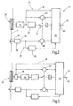
- FIG. 1 there is illustrated a yarn feeding device 1 for supplying a plurality of yarns 2 to a knitting machine 3 or an otherwise yarn-consuming machine.
- the threads 2 are supplied in groups by four individual threads 4, 5, 6, 7 of a first group 8 of yarn feeding devices 11, 12, 13, 14 is supplied to the knitting machine 3.
- Further threads 15, 15a, 15b are supplied to the knitting machine 3 by a second group 16 of yarn feeding devices 17, 18, 19.
- Each yarn feeding device 11, 12, 13, 14, 17, 18, 19 pulls its respective thread 4, 5, 6, 7, or 15, 15a, 15b from a yarn package 21, 22, 23, 24, 25, 26, 27 from.
- All yarn feeding devices 11, 12, 13, 14 and 17, 18, 19 are connected to a central unit 31, which gives the yarn feeding devices 11, 12, 13, 14, 17, 18, 19 control commands.
- a data bus 32 For command transmission is a data bus 32, to which all yarn feeding devices 11, 12, 13, 14, 17, 18, 19 and the central unit 31 are connected. Via the data bus 32, the yarn feeding devices 11, 12, 13, 14, 17, 18, 19 receive commands at least in groups and individually send data to the central processing unit 31.
- FIG. 2 schematically illustrates the structure of the yarn feeding device 11 by way of example for all other yarn feeding devices 12, 13, 14, 17, 18, 19. The following description applies accordingly for all yarn feeding devices:
- the yarn feeding device 11 has a yarn feed wheel 33, which is looped by the yarn 4 to be supplied to the knitting machine 3 in several turns.
- the yarn feeding device is connected to the drive shaft of a motor 34 which is operable at different speeds. It is for example a DC motor, a servomotor or a stepper motor. In the present example FIG. 2 It is assumed that the motor 34 is a permanent magnet DC motor.
- the thread 4 after it has left the yarn feed wheel 33, passes over a movable element 35, for example a feeler pin of a yarn tension sensor 36, which delivers a yarn tension signal at its output 37.
- the yarn tension sensor 36 is part of a yarn tension regulator 38.
- a summer 39 with which the difference between a yarn tension setpoint signal and the pending at the output 37 yarn tension actual signal is formed.
- This difference is supplied via a switch block 41 to a control amplifier 42, which serves as a drive circuit for the motor 34.
- the target signal for the thread tension is provided by a control unit 43. This also controls the switch block 41.
- the yarn feeding devices 11, 12, 13, 14, 17, 18, 19 are positive yarn feeding devices. This means that the yarn feed wheel is looped by several turns of thread, preferably more than four turns of thread, whereby the thread is conveyed without slip. However, it is considered to be quite advantageous in some applications, to allow a certain amount of slippage between yarn feed wheel and thread. This can be done by only a few turns, for example, only two or three turns of thread are wrapped around the yarn feed wheel.
- one or more fixed or movably mounted Fadenabhebeieri can be arranged in the vicinity of the Fadenarrirads over which run one or more turns of thread.
- the Fadenabhebeieri can be, for example, substantially parallel to the axis of rotation of the Fadenarrirads aligned pins.
- the Fadenunterrad rotate faster under the thread
- the lag of the thread relative to the yarn feed wheel can occur or occurs both in the trial phase and in the production phase.
- the yarn feed wheel can rotate 10% faster than yarn is delivered. If the Fadenabhebeimplantation fixed, ie not adjustable by the thread tension, arranged, usually occurs on a predictable and reproducible slip.
- the yarn feeding device 11 contains, in addition to the yarn tension regulator 38, a delivery quantity regulator, which is designated here as a yarn speed regulator 44. To this belongs a summer 45, which forms the difference between a yarn speed setpoint signal and a yarn speed actual signal. This difference is supplied to the switch block 41 and via this, given the same position, to the input of the control amplifier 42.
- the actual yarn speed signal can be tapped as a voltage signal at the output of the control amplifier 42 when the operating voltage of the motor 34 corresponds to its speed with sufficient accuracy.
- Its yarn speed setpoint signal is received by the speed controller 44 from the control unit 43. This is also fed via a line branch 46, a signal corresponding to the yarn speed.
- the control unit 43 has an input 47 which is connected to the data bus 32.
- the central unit 31 is illustrated in simplified form.
- the central unit 31 has a communication block 48, which both individual yarn feeding devices 11, 12, 13, 14, 17, 18, 19 respond, and send data to these, as well Data from these can be received.
- the communication block 48 is connected to an averager 49, which is adapted to form the average of numerical values supplied by the communication block 48 and the yarn delivery speeds of the individual yarn feeding devices 11, 12, 13, 14 and 17, 18, 19 of a group 8 or 16 mark.
- the communication block 48 can send signals to the individual yarn feeding devices 11, 12, 13, 14 and 17, 18, 19, which in turn cause their control unit 43, the respective switch blocks 41 to switch so that either the yarn tension regulator 38 or the yarn speed controller 44th is active.
- the signal provided by the averager 49 is fed to a multiplication block 51 which multiplies the signal formed by the averager 49 by a normalized engine speed signal. This is obtained via a corresponding receiving block 52, which is connected to a rotational speed sensor of the knitting machine 3.
- the multiplication block 51 supplies a signal to the communication block 48, which supplies the signal thus determined as a thread speed target signal to the yarn feeding devices.
- an input device 53 is connected, which serves to switch the thread supply device 1 of trial operation in regular operation and make other inputs. Further details can be found in the following functional description:
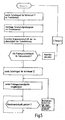
- the thread supply device 1 is a positive delivery device, which also has a trial mode.
- the input device operated accordingly, so that the central unit 31 sends a Probe
- the central unit 31 sends a Probe
- the switch blocks 41 of the respective, belonging to the addressed group 8 or 16 yarn feeding devices in the in FIG. 2 illustrated lower position in which the thread tension regulator 38 are activated.
- the CPU 31 now sends a yarn tension command signal given from the respective control unit 43 to the yarn tension controller 38.
- the thread tension regulator regulates the desired thread tension on each yarn feeding device.
- the averaged yarn speed (yarn delivery amount per machine revolution) as the setpoint for the connected Yarn feeding devices 11, 12, 13, 14, 17, 18, 19 basis.
- the communication block 48 first sends a switching signal to the switch blocks 41 of the individual yarn feeding devices 11, 12, 13, 14, 17, 18, 19. These thus turn on the yarn speed controller 44. From now on, the central unit 31 transmits, if the machine speed changes, the yarn speed signal generated in the multiplication block 51 to the connected yarn feeding devices, so that they supply respective yarn amounts or yarn speeds in groups.
- the thread tensions of the threads 4, 5, 6, 7 of the group 8 can thus differ considerably, but because of the positive delivery, i. the supply of fixed amounts of thread per unit time reaches a uniform mesh size. The same applies to the threads 15, 15a, 15b of the group 16.
- receive block 52 has in FIG. 4 an alternative task: he does not constantly calculate thread speed default values again based on the machine speed but only undertakes this once at the end of the trial run. Thereafter, this speed is sent as a coefficient to the yarn feeding devices 11, 12, 13, 14, 17, 18, 19 and stored there. The yarn feeding devices then receive signals that identify the current machine speed. The conversion of the yarn delivery speed of the test operation to the current machine speed then takes place in the control units 43.
- the yarn feeding device 11 after FIG. 2 may also include a tester 55 which is the one from the yarn tension sensor 36 detected thread tension constantly or as needed checked.
- the input of the test device 55 is connected to the output 37.
- FIG. 3 illustrates a further modified embodiment of the yarn feeding device 11.
- the deviation consists in the detection of the rotational speed of the motor 34 and the angular position of its Fadenarrirads 33.
- the motor 34 and its output is connected to a speed sensor 56 whose output to the adder 45 and is connected via the line branch 46 to the control unit 43. Otherwise, the intended function description applies.
- a yarn supply device 1 contains a plurality of yarn feeding devices 11, 12, 13, 14 which are combined to form a group 8.
- the yarn feeding devices 11, 12, 13, 14 operate individually controlled by voltage based on a given thread tension value.
- the yarn delivery quantities or yarn speeds resulting from this at the individual yarn feeding devices 11, 12, 13, 14 are reported to a central processing unit. This calculates from the reported yarn speeds a group average and sends it as a default value for subsequent operation of the yarn feeding devices 11, 12, 13, 14. This allows the individual yarn feeding devices 11, 12, 13, 14 below work in pure positive mode.
- the central unit 31 via an input 57, both signals that characterize the machine speed (speed) and pattern signals, based on which the yarn feeding devices of each group to be addressed 8 and 16 on and off or accelerated or slowed down.
Landscapes
- Engineering & Computer Science (AREA)
- Textile Engineering (AREA)
- Knitting Machines (AREA)
Abstract
Claims (16)
- Procédé de délivrance de fils (4, 5, 6, 7, 15, 15a, 15b) à une machine textile, destiné en particulier au fonctionnement d'appareils (11, 12, 13, 14) de délivrance de fils, caractérisé en ce que les appareils de délivrance de fils sont mis en fonctionnement avec un réglage de la tension mécanique dans une phase d'essai, les vitesses de fil produites par les appareils de délivrance de fils, ou les quantités de fil délivrées étant saisies, et en ce qu'une fois la phase d'essai terminée les appareils de délivrance de fils sont mis en fonctionnement en faisant l'objet d'un réglage de tension et d'une répartition selon une prescription de vitesse, ou une prescription de quantité de fil qui ont été établies à partir des vitesses ou des quantités de fil qui ont été saisies.
- Procédé selon la revendication 1, caractérisé en ce que les appareils de délivrance de fils sont mis en fonctionnement, lors de la phase d'essai, avec des tensions assignées concordantes.
- Procédé selon la revendication 1, caractérisé en ce que les vitesses de fil, ou les quantités de fil produites par les appareils de délivrance de fils sont fournies à une unité centrale par l'intermédiaire d'un conducteur de signal.
- Procédé selon la revendication 1, caractérisé en ce que les vitesses de fil, ou les quantités de fil sont fournies à une unité centrale sous forme de données numériques.
- Procédé selon la revendication 1, caractérisé en ce que la prescription de vitesse, ou de quantité, est établie à partir des vitesses de fil ou des quantités de fil de tous les appareils de délivrance de fils appartenant à un groupe d'appareils de délivrance de fils.
- Procédé selon la revendication 1, caractérisé en ce que la prescription de vitesse, ou de quantité, est fixée proportionnellement à la vitesse de fonctionnement de machine d'une machine destinée à former des mailles, qui reçoit des fils.
- Procédé selon la revendication 1, caractérisé en ce que la prescription de vitesse, ou de quantité, des appareils de délivrance de fils est déterminée en calculant une valeur moyenne à partir de plusieurs vitesses de fil ou de plusieurs quantités de fil.
- Procédé selon la revendication 7, caractérisé en ce que les vitesses de fil sont soumises à une pondération avant ou pendant le calcul de la valeur moyenne.
- Procédé selon la revendication 1, caractérisé en ce qu'un signal d'erreur est émis lorsque, lors du fonctionnement d'essai, il se produit des différences entre des vitesses de fil individuelles, ou entre des quantités de fil individuelles, qui dépassent une valeur prescrite.
- Procédé selon la revendication 1, caractérisé en ce qu'un signal d'erreur est émis lorsqu'une fois le fonctionnement d'essai terminé, il se produit des différences de tension de fil qui dépassent une valeur prescrite.
- Procédé selon la revendication 1, caractérisé en ce que les prescriptions de vitesse ou les données de quantité en rapport avec la vitesse de fonctionnement de machine sont transmises sous forme de signaux d'une unité centrale aux appareils de délivrance de fils et y sont mises en mémoire.
- Procédé selon la revendication 1, caractérisé en ce que les prescriptions de vitesse ou les données de quantité en rapport avec la vitesse de fonctionnement de machine sont transmises sous forme de signaux numériques d'une unité centrale aux appareils de délivrance de fils et y sont mises en mémoire.
- Installation (1) de délivrance de fils destinée à la délivrance, selon le procédé de la revendication 1, de plusieurs fils (4, 5, 6, 7, 15, 15a, 15b) aux postes d'utilisation de fils,
caractérisée en ce qu'elle comporte plusieurs appareils (11, 12, 13, 14) de délivrance de fils, qui forment un groupe (8), et dont au moins quelques uns présentent un capteur (36) de tension de fil, un moteur d'entraînement (34) doté d'une roue de délivrance de fils (33), un dispositif (38) de réglage de la tension de fil et un dispositif (44) de réglage de la vitesse de fil, et en ce qu'elle comporte une unité centrale (31) qui est reliée aux appareils (11, 12, 13, 14) de délivrance de fils, en vue de recevoir de ceux-ci des signaux concernant la vitesse de fil ou des signaux concernant la quantité de fil et pour envoyer à ceux-ci des prescriptions de vitesse de fil ou des prescriptions de quantité de fil. - Installation de délivrance de fils selon la revendication 13, caractérisée en ce que le dispositif (38) de réglage de tension de fil et le dispositif (44) de réglage de vitesse de fil peuvent être activés alternativement par l'intermédiaire d'un bloc de commutation (41).
- Installation de délivrance de fils selon la revendication 13, caractérisée en ce que l'unité centrale (31) présente une unité de calcul (49, 51) qui détermine un signal de prescription de vitesse de fil ou un signal de prescription de quantité de fil à partir de signaux concernant la vitesse de fil qui ont été reçus.
- Installation de délivrance de fils selon la revendication 13, caractérisée en ce que l'unité centrale (31) présente une entrée (52) pour un signal qui caractérise la vitesse de fonctionnement de la machine (3) destinée à la formation de mailles.
Applications Claiming Priority (3)
| Application Number | Priority Date | Filing Date | Title |
|---|---|---|---|
| DE10234545A DE10234545B4 (de) | 2002-07-30 | 2002-07-30 | Verfahren und Vorrichtung zum Liefern von Fäden |
| DE10234545 | 2002-07-30 | ||
| PCT/DE2003/002065 WO2004016843A1 (fr) | 2002-07-30 | 2003-06-20 | Procede et dispositif d'alimentation en fils |
Publications (2)
| Publication Number | Publication Date |
|---|---|
| EP1525344A1 EP1525344A1 (fr) | 2005-04-27 |
| EP1525344B1 true EP1525344B1 (fr) | 2008-10-15 |
Family
ID=30469157
Family Applications (1)
| Application Number | Title | Priority Date | Filing Date |
|---|---|---|---|
| EP03787606A Expired - Lifetime EP1525344B1 (fr) | 2002-07-30 | 2003-06-20 | Procede et dispositif d'alimentation en fils |
Country Status (8)
| Country | Link |
|---|---|
| US (1) | US7303163B2 (fr) |
| EP (1) | EP1525344B1 (fr) |
| KR (1) | KR100647453B1 (fr) |
| CN (1) | CN100436682C (fr) |
| AU (1) | AU2003246539A1 (fr) |
| DE (2) | DE10234545B4 (fr) |
| TW (1) | TWI238864B (fr) |
| WO (1) | WO2004016843A1 (fr) |
Families Citing this family (23)
| Publication number | Priority date | Publication date | Assignee | Title |
|---|---|---|---|---|
| DE102004009057A1 (de) * | 2004-02-23 | 2005-09-08 | Memminger-Iro Gmbh | Elektronischer Positivfournisseur |
| DE102004017045B3 (de) * | 2004-04-02 | 2005-12-08 | Memminger-Iro Gmbh | Vorrichtung und Verfahren zur Fadenpositivlieferung |
| ITTO20050225A1 (it) * | 2005-04-06 | 2006-10-07 | Lgl Electronics Spa | Alimentatore positivo di filato per macchine tessili e simili |
| WO2007048528A1 (fr) * | 2005-10-27 | 2007-05-03 | Memminger-Iro Gmbh | Dispositif de controle entierement automatique de longueur de fil |
| DE102005057352B3 (de) * | 2005-12-01 | 2007-08-23 | Memminger-Iro Gmbh | Verfahren und Einrichtung zur Bestimmung der Fadenmenge an einer Strickmaschine |
| DE602007004983D1 (de) * | 2007-08-31 | 2010-04-08 | Lgl Electronics Spa | Verfahren zur Spannungskontrolle eines Garnes, das von einem negativen Liefergerät an eine Textilmaschine geliefert wird, und Vorrichtung zur Durchführung des Verfahrens |
| WO2009052846A1 (fr) * | 2007-10-24 | 2009-04-30 | Memminger-Iro Gmbh | Dispositif de livraison de fil à régulateur adaptatif |
| ATE530687T1 (de) * | 2009-07-03 | 2011-11-15 | Lgl Electronics Spa | Verfahren zur erkennung des anhaltens der garnabwicklung von einer garnzufuhr mit stationärer trommel |
| ITMI20100887A1 (it) * | 2010-05-18 | 2011-11-19 | Btsr Int Spa | Metodo e dispositivo perfezionato per alimentare un filo ad una macchina operatrice con tensione e velocita' costante |
| US20130186055A1 (en) * | 2010-09-25 | 2013-07-25 | Vladimir Bram | System and method for the management of the flow rate of a feed line |
| IT1402874B1 (it) * | 2010-11-19 | 2013-09-27 | Btsr Int Spa | Dispositivo di alimentazione di un filo ad una macchina tessile con organo di taglio del filo |
| DE102012103535B3 (de) * | 2012-04-20 | 2013-10-10 | Memminger-Iro Gmbh | Vorrichtung und Verfahren zur Überwachung der Produktion einer Strickmaschine |
| JP5999744B1 (ja) * | 2014-12-10 | 2016-09-28 | 内野株式会社 | 多重ガーゼの製織方法および多重ガーゼ織物 |
| EP3103749B1 (fr) * | 2015-06-12 | 2019-12-04 | L.G.L. Electronics S.p.A. | Procédé pour commander le taux de consommation d'un fil déroulé à partir d'un dispositif d'alimentation à accumulation vers une machine textile et appareil permettant de mettre en oeuvre ce procédé |
| DE102015120264B3 (de) * | 2015-11-23 | 2016-12-29 | Memminger-Iro Gmbh | Verfahren zur Steuerung der Fadenlieferung mindestens eines Fadenliefergerätes und Textilmaschine mit einem System mit mindestens einem Fadenliefergerät |
| EP3460113B1 (fr) * | 2017-09-20 | 2021-05-05 | KARL MAYER STOLL R&D GmbH | Procédé de fonctionnement d'un métier à mailles jetées et métier à mailles jetées |
| IT201700113434A1 (it) * | 2017-10-10 | 2019-04-10 | Lgl Electronics Spa | Metodo di controllo del consumo di filato in un processo di tessitura |
| DE102017128327B3 (de) | 2017-11-29 | 2019-01-10 | Memminger-Iro Gmbh | Verfahren zur Steuerung der Lieferung von Fäden eines Systems mit mehreren Fadenliefergeräten und Textilmaschine mit einem System mit mehreren Fadenliefergeräten |
| CN108363370B (zh) * | 2018-02-07 | 2020-10-23 | 江南大学 | 带热延伸机的经编机电子送纱控制系统及方法 |
| JP7307573B2 (ja) * | 2018-03-30 | 2023-07-12 | 株式会社島精機製作所 | 横編機 |
| KR102393871B1 (ko) * | 2019-06-18 | 2022-05-02 | 가부시키가이샤 시마세이키 세이사쿠쇼 | 횡편기의 톱 텐션장치의 설정방법 및 설정시스템 |
| JP7462459B2 (ja) | 2019-06-18 | 2024-04-05 | 株式会社島精機製作所 | 横編機の天バネ装置の設定方法及び設定システム |
| CN114737290B (zh) * | 2022-03-18 | 2023-02-28 | 浙江理工大学 | 一种多组纱线输出张紧力智能阶梯式调节装置 |
Family Cites Families (12)
| Publication number | Priority date | Publication date | Assignee | Title |
|---|---|---|---|---|
| US358416A (en) * | 1887-02-22 | Island | ||
| US3858416A (en) * | 1973-07-23 | 1975-01-07 | Eugene F White | Knitting machine yarn feeding apparatus |
| GB1584259A (en) * | 1976-08-16 | 1981-02-11 | Iro Ab | Methods and apparatus for knitting machine control systems |
| CN85106247A (zh) * | 1985-08-19 | 1987-02-18 | 古斯塔夫·梅明格 | 纺织机械供纱装置 |
| US4744227A (en) * | 1987-06-23 | 1988-05-17 | Whitener Jr Charles G | Pattern monitoring method and apparatus |
| JPH084999B2 (ja) * | 1987-07-07 | 1996-01-24 | トッキ株式会社 | 細線材の研磨方法並びにその装置 |
| DE3824034C1 (fr) * | 1988-07-15 | 1989-09-14 | Gustav 7290 Freudenstadt De Memminger | |
| IT1242051B (it) | 1990-04-20 | 1994-02-02 | Tiziano Barea | Perfezionamenti relativi al controllo del corretto assorbimento dei fili utilizzati in una macchina tessile,in particolare per maglieria o calzetteria |
| IT1243970B (it) * | 1990-12-04 | 1994-06-28 | Flavio Barea | Metodo e dispositivo per il controllo automatico della quantita' di filo alimentato ad una macchina tessile operante su di esso, in modo discontinuo. |
| DE19537325C1 (de) * | 1995-10-06 | 1996-11-28 | Memminger Iro Gmbh | Fadenliefergerät mit elektronischer Ansteuerung |
| US6015109A (en) * | 1995-10-16 | 2000-01-18 | Memminger-Iro Gmbh | Thread feed device |
| IT1314900B1 (it) * | 2000-06-27 | 2003-01-16 | Sangiacomo Spa | Metodo di misura e controllo continuativi della tensione e/oscorrimento dei fili alimentati in macchine per lavorazioni a maglia. |
-
2002
- 2002-07-30 DE DE10234545A patent/DE10234545B4/de not_active Expired - Fee Related
-
2003
- 2003-06-20 KR KR1020057001492A patent/KR100647453B1/ko not_active IP Right Cessation
- 2003-06-20 WO PCT/DE2003/002065 patent/WO2004016843A1/fr not_active Application Discontinuation
- 2003-06-20 CN CNB038180677A patent/CN100436682C/zh not_active Expired - Fee Related
- 2003-06-20 AU AU2003246539A patent/AU2003246539A1/en not_active Abandoned
- 2003-06-20 DE DE50310651T patent/DE50310651D1/de not_active Expired - Fee Related
- 2003-06-20 EP EP03787606A patent/EP1525344B1/fr not_active Expired - Lifetime
- 2003-06-20 US US10/523,224 patent/US7303163B2/en not_active Expired - Fee Related
- 2003-07-29 TW TW092120586A patent/TWI238864B/zh not_active IP Right Cessation
Also Published As
| Publication number | Publication date |
|---|---|
| KR20050026022A (ko) | 2005-03-14 |
| DE10234545B4 (de) | 2005-12-15 |
| US20060184267A1 (en) | 2006-08-17 |
| CN100436682C (zh) | 2008-11-26 |
| EP1525344A1 (fr) | 2005-04-27 |
| WO2004016843A1 (fr) | 2004-02-26 |
| TWI238864B (en) | 2005-09-01 |
| DE10234545A1 (de) | 2004-02-19 |
| KR100647453B1 (ko) | 2006-11-23 |
| CN1671903A (zh) | 2005-09-21 |
| DE50310651D1 (de) | 2008-11-27 |
| US7303163B2 (en) | 2007-12-04 |
| AU2003246539A1 (en) | 2004-03-03 |
| TW200413589A (en) | 2004-08-01 |
Similar Documents
| Publication | Publication Date | Title |
|---|---|---|
| EP1525344B1 (fr) | Procede et dispositif d'alimentation en fils | |
| DE69916693T3 (de) | Vorrichtung zum Steuern der Fadenlieferung zu einer Textilmaschine und Verfahren zum Steuern des Betriebs der Maschine und der Produktion | |
| EP1370720B1 (fr) | Procede de reglage/surveillance de production d'un metier a tricoter circulaire et dispositif de reglage/surveillance de production | |
| EP0945534A2 (fr) | Fournisseur positif à faible inertie pour des fils élastomères | |
| DE102013110988B4 (de) | Verfahren und Vorrichtung zur Überwachung der Produktion einer Strickmaschine sowie Strickmaschine | |
| EP1238273A2 (fr) | Procede pour commander une machine a texturer, et machine a texturer | |
| EP3060506B1 (fr) | Galette et procédé de commande d'une galette | |
| CH666243A5 (de) | Spulmaschine mit mindestens zwei spulstellen zum herstellen der wicklung einer kreuzspule. | |
| EP1595008A1 (fr) | Machine textile | |
| DE10348689A1 (de) | Verfahren zum Herstellen eines Effektgarnes | |
| DE60006644T2 (de) | VERFAHREN UND VORRICHTUNG ZUM DOPPELN ODER KABLIEREN VON ZWEI ODER MEHREREN GARNEN BEIM ZUFüHREN AN TEXTILMASCHINEN ZUR HERSTELLUNG VON STRICKWAREN, MIEDERWAREN UND DERGLEICHEN | |
| DE2432938B2 (de) | Verfahren und vorrichtung zur fadenlaengenmessung in einer textilmaschine mit mehreren wickelstationen | |
| DE3629699A1 (de) | Verfahren zur digitalen fadenlaengen-kontrolle an textilmaschinen | |
| EP3075690B1 (fr) | Procede et dispositif de surveillance de la production d'une machine a tricoter et machine a tricoter | |
| EP1067224B1 (fr) | Procédé et dispositif de surveillance de la qualité des fils | |
| WO2002002856A2 (fr) | Dispositif d'alimentation en fils pour machines textiles | |
| EP1709222B1 (fr) | Procede pour produire un file fantaisie | |
| EP1733085A1 (fr) | Dispositif et procede d'alimentation posivive en fils | |
| DE102012103535B3 (de) | Vorrichtung und Verfahren zur Überwachung der Produktion einer Strickmaschine | |
| EP0362521A2 (fr) | Méthode et dispositif de contrôle électronique d'alimentation de plusieurs fils individuels pour machines textiles | |
| EP1432855B1 (fr) | Procede de commande d'une machine a texturer et machine a texturer | |
| EP3374547B1 (fr) | Procédé de contrôle de la qualité lors de la texturation et dispositif de texturation | |
| DE10005101A1 (de) | Verfahren und Vorrichtung zur Herstellung einer Strick- oder Wirkware sowie Fadenliefergerät für eine Strick- oder Wirkmaschine bzw. Garnproduktionsmaschine | |
| DE102012025607A1 (de) | Vorrichtung und Verfahren zur Überwachung der Produktion einer Strickmaschine | |
| WO2001034891A1 (fr) | Procede et dispositif de fabrication d'un article tricote, et appareil d'alimentation en fil pour une machine a tricoter ou pour une machine de production de fil |
Legal Events
| Date | Code | Title | Description |
|---|---|---|---|
| PUAI | Public reference made under article 153(3) epc to a published international application that has entered the european phase |
Free format text: ORIGINAL CODE: 0009012 |
|
| 17P | Request for examination filed |
Effective date: 20041207 |
|
| AK | Designated contracting states |
Kind code of ref document: A1 Designated state(s): AT BE BG CH CY CZ DE DK EE ES FI FR GB GR HU IE IT LI LU MC NL PT RO SE SI SK TR |
|
| AX | Request for extension of the european patent |
Extension state: AL LT LV MK |
|
| DAX | Request for extension of the european patent (deleted) | ||
| RBV | Designated contracting states (corrected) |
Designated state(s): DE IT TR |
|
| GRAP | Despatch of communication of intention to grant a patent |
Free format text: ORIGINAL CODE: EPIDOSNIGR1 |
|
| GRAS | Grant fee paid |
Free format text: ORIGINAL CODE: EPIDOSNIGR3 |
|
| GRAA | (expected) grant |
Free format text: ORIGINAL CODE: 0009210 |
|
| AK | Designated contracting states |
Kind code of ref document: B1 Designated state(s): DE IT TR |
|
| REF | Corresponds to: |
Ref document number: 50310651 Country of ref document: DE Date of ref document: 20081127 Kind code of ref document: P |
|
| PLBE | No opposition filed within time limit |
Free format text: ORIGINAL CODE: 0009261 |
|
| STAA | Information on the status of an ep patent application or granted ep patent |
Free format text: STATUS: NO OPPOSITION FILED WITHIN TIME LIMIT |
|
| 26N | No opposition filed |
Effective date: 20090716 |
|
| PGFP | Annual fee paid to national office [announced via postgrant information from national office to epo] |
Ref country code: IT Payment date: 20090626 Year of fee payment: 7 |
|
| PG25 | Lapsed in a contracting state [announced via postgrant information from national office to epo] |
Ref country code: DE Free format text: LAPSE BECAUSE OF NON-PAYMENT OF DUE FEES Effective date: 20100101 |
|
| PG25 | Lapsed in a contracting state [announced via postgrant information from national office to epo] |
Ref country code: IT Free format text: LAPSE BECAUSE OF NON-PAYMENT OF DUE FEES Effective date: 20100620 |
|
| PG25 | Lapsed in a contracting state [announced via postgrant information from national office to epo] |
Ref country code: TR Free format text: LAPSE BECAUSE OF FAILURE TO SUBMIT A TRANSLATION OF THE DESCRIPTION OR TO PAY THE FEE WITHIN THE PRESCRIBED TIME-LIMIT Effective date: 20081015 |