EP1525150B1 - Vorrichtung zum fangen eines fadens am anfang einer spulreise - Google Patents
Vorrichtung zum fangen eines fadens am anfang einer spulreise Download PDFInfo
- Publication number
- EP1525150B1 EP1525150B1 EP03766270A EP03766270A EP1525150B1 EP 1525150 B1 EP1525150 B1 EP 1525150B1 EP 03766270 A EP03766270 A EP 03766270A EP 03766270 A EP03766270 A EP 03766270A EP 1525150 B1 EP1525150 B1 EP 1525150B1
- Authority
- EP
- European Patent Office
- Prior art keywords
- bushing
- catching
- thread
- guiding
- slit
- Prior art date
- Legal status (The legal status is an assumption and is not a legal conclusion. Google has not performed a legal analysis and makes no representation as to the accuracy of the status listed.)
- Expired - Lifetime
Links
- 238000004804 winding Methods 0.000 claims abstract description 80
- 230000008859 change Effects 0.000 claims abstract description 22
- 239000013013 elastic material Substances 0.000 claims description 3
- 238000000034 method Methods 0.000 description 7
- 230000008569 process Effects 0.000 description 6
- 230000009471 action Effects 0.000 description 3
- 210000003128 head Anatomy 0.000 description 3
- 230000004323 axial length Effects 0.000 description 2
- 230000015572 biosynthetic process Effects 0.000 description 2
- 238000013461 design Methods 0.000 description 2
- 239000000463 material Substances 0.000 description 2
- 239000002184 metal Substances 0.000 description 2
- 210000001331 nose Anatomy 0.000 description 2
- 239000007787 solid Substances 0.000 description 2
- 238000012549 training Methods 0.000 description 2
- 240000000731 Fagus sylvatica Species 0.000 description 1
- 235000010099 Fagus sylvatica Nutrition 0.000 description 1
- 241000209035 Ilex Species 0.000 description 1
- 241000692569 Stylephorus chordatus Species 0.000 description 1
- 230000002411 adverse Effects 0.000 description 1
- 238000005520 cutting process Methods 0.000 description 1
- 230000003247 decreasing effect Effects 0.000 description 1
- 230000006735 deficit Effects 0.000 description 1
- 238000011161 development Methods 0.000 description 1
- 230000018109 developmental process Effects 0.000 description 1
- 230000003292 diminished effect Effects 0.000 description 1
- 238000006073 displacement reaction Methods 0.000 description 1
- 230000000694 effects Effects 0.000 description 1
- 238000009434 installation Methods 0.000 description 1
- 238000004519 manufacturing process Methods 0.000 description 1
- 238000000926 separation method Methods 0.000 description 1
- 238000012546 transfer Methods 0.000 description 1
- 230000007704 transition Effects 0.000 description 1
Images
Classifications
-
- B—PERFORMING OPERATIONS; TRANSPORTING
- B65—CONVEYING; PACKING; STORING; HANDLING THIN OR FILAMENTARY MATERIAL
- B65H—HANDLING THIN OR FILAMENTARY MATERIAL, e.g. SHEETS, WEBS, CABLES
- B65H65/00—Securing material to cores or formers
-
- B—PERFORMING OPERATIONS; TRANSPORTING
- B65—CONVEYING; PACKING; STORING; HANDLING THIN OR FILAMENTARY MATERIAL
- B65H—HANDLING THIN OR FILAMENTARY MATERIAL, e.g. SHEETS, WEBS, CABLES
- B65H2701/00—Handled material; Storage means
- B65H2701/30—Handled filamentary material
- B65H2701/31—Textiles threads or artificial strands of filaments
Definitions
- the present invention relates to a device for catching a continuously arriving at a winder with at least two winding spindles thread at the beginning of a winding cycle and for winding the thread to a coil on an attachable to the winding spindle sleeve, wherein the device is arranged at the free end of the winding spindle catching bush having a catch slot and arranged in the center of the catch bushing friction pin.
- the winder has at least two winding spindles to allow automatic bobbin change.
- these two winding spindles are arranged on a turntable and are alternately pivoted into an operating position, while the wound coil just wound is removed from the winding spindle, which is not in the operating position, and a new sleeve is pushed on.
- an automatic bobbin change it is necessary to cut the thread. With this separation process, the end of the thread is determined on the just finished wound coil at the same time. On the other hand, a thread beginning is formed, with which the winding cycle begins on the new sleeve. It is important to create the thread after production or after a business interruption for the first time. This is done by hand, ie using a suction gun. This unique process is then followed by any number of automatic bobbin changes.
- the part of the thread which usually runs over a head thread guide or a traversing thread guide in front of a coil in the operating position, is called “incoming thread”.
- the thread between the thread guide or traversing thread guide and the winding spindle in operation is called the “running thread”.
- the “running thread” is the Part of the thread that is between the winding spindle in operation and the almost fully wound coil.
- Each winding spindle has at its free end a device for catching the thread.
- This device consists essentially of two parts, namely a catching bush with catching slot and a coaxially arranged friction pin.
- the catch bushing is a bush or sleeve-shaped part with an axial length of a few centimeters.
- the outer diameter of the catch bush is equal to or slightly smaller than the outer diameter of the winding spindle.
- the inner diameter of the catch bushing is slightly smaller, so that a solid claimable body is formed, but which is still usually designed as a plastic body.
- catch slot In the front side of the catch bushing begins a catch slot which is arranged obliquely to the generatrix of the catch bushing or to the axis of the winding spindle.
- the angle at which the catching slot is arranged obliquely is relatively large, ie the catching slot is arranged comparatively steeply.
- the catch slot begins at the front edge open and ends edge-closed in a certain axial depth in the catch bushing.
- the catching bushing is arranged on the winding spindle such that at least the axial region in which the catching slot extends is not covered by a sleeve which has been properly pushed on and fixed.
- the catching slot is arranged in a coordinated manner with respect to the direction of rotation of the winding spindle in order to be able to introduce a thread, which is approximated from the end face, into the catching slot.
- the friction pin In the interior of the extent hollow trained catch bush the friction pin is arranged, which has a substantially smaller outer diameter, as it corresponds to the inner diameter of the catch bushing.
- an annular space is created between friction pin and catch bush, in which the front end of a suction gun can be inserted by hand and thus the thread can be created.
- the friction pin has the task of exerting by winding the thread on it with a rotating winding spindle a certain amount of friction on the thread, which serves to achieve a fixation of the thread.
- the overall friction which leads to a fixing, so a setting of the thread, is also determined by several influencing variables, such as the formation of the bottom of the catch slot, in which a deflection of the thread takes place.
- Another Frictional component is generated by the portion of the thread which forms immediately after entering the catching slot on the outer circumference of the catching bushing.
- Such a device is also known from US-A-4,205,800.
- This known device for catching a continuously arriving at a winder yarn allows only manual application with a suction gun, which must be repeated at each coil at the beginning of the winding cycle.
- the incoming thread is sucked by the suction gun, so made manageable.
- the front end of the suction gun is inserted into the clearance between the friction pin and the catch bushing.
- the thread can run into the catching slot.
- the thread is sucked off further via the suction gun.
- an increase in friction takes place on the thread.
- the thread is guided by the Fadenleitwerk or the traversing yarn guide accordingly.
- the known device is already advantageous in that it allows the use of normal cylindrical sleeves without any catching device.
- the device for catching is located on each winding spindle and is therefore available again for each coil winding.
- the disadvantage is that the known device merely applying the thread by hand, d. H. with a suction gun. An automatic bobbin change is not possible.
- a further development direction of a capture device is known.
- the sleeve is held here on the right and left by a respective centering plate, so that the possibility exists to use normal sleeves.
- One of the centering plate is designed as a catching device in a special way, d. H. occupied with catch noses.
- the catch noses are arranged on a larger diameter than corresponds to the outer diameter of the sleeve. Again, the catching of the thread takes place in conjunction with a traversing yarn guide.
- a disadvantage of this device is that to a bobbin change, the two centering plates must be removed from each other. This makes the training and the drive of the centering plate consuming. Such a catching device is indeed suitable for automatic yarn transfer.
- the invention has the object of developing a device of the type described above so that on the one hand the application of the thread by hand, ie with a suction gun, z. B. after a business interruption, and subsequently an automatic bobbin change when using normal sleeves without capture range is possible.
- this is achieved in a device of the type described above in that on each winding spindle in addition to the catch bushing a guide bush is provided with guide slot which surrounds the catch bushing in the radial direction and is arranged axially offset from the catch bush, and that between the catch bushing and the guide bush a clamping device is provided for fixing the thread during automatic bobbin change.
- the new device further forms the generic device. It uses the generic device to realize the benefits of applying by hand, as is required after a break in work.
- the catching bush with catching slot is associated with a guide bushing with a guide slot.
- the guide bush has a larger diameter than the catch bush and closes - seen axially in the winding spindle direction - to the catch bushing inwards, ie in the direction of the coil to be formed on.
- the guide bush has an end face which is arranged axially under overlapping with the catch slot of the catch bush.
- the guide bush thus surrounds the catch bush in a small axial area.
- the outer diameter of the guide bushing is equal to or smaller than the inner diameter of the sleeves used.
- the guide bush has a guide slot which is assigned to the catching slot of the catching bush so that a connection of the two slots to one another is possible at least in the axial direction. Since the device fulfills its function when the winding spindle is rotating, it is not necessary to associate the catching slot with the guide slot in certain angular ranges. Of course, the guide slot must be arranged on the same side obliquely to the surface line of the guide bush or to the axis of the winding spindle as the catch slot. Although the catch bush and the guide bushing are arranged at different diameters, they differ relatively little in their diameter jump, while still a large diameter jump is required between the catch bush and the friction bolt, as is necessary for manual application of the thread.
- a clamping device for fixing the thread during automatic bobbin change is provided between catch bushing and guide bushing.
- This clamping device serves to fix the thread, so set so that it is stationary relative to this nip.
- This fixation is used in two ways. On the one hand, it serves to cut through the thread, ie the expiring Thread to allow the almost finished wound coil. In the other direction, the beginning of the running thread is formed and placed on the winding spindle, so that a new winding is started on a new sleeve.
- the first application process by means of a suction gun by hand can be carried out as follows:
- the incoming thread is picked up by the suction gun and sucked off.
- the front end of the suction gun is inserted into the space between the friction pin and the catch bushing.
- contact is made with the thread on the front side of the catch bushing.
- the thread enters the catch slot.
- the relative position of the guide slot on the guide bush initially results in a few wraps on the circumference of the catch bushing with subsequent passage of the thread in the guide slot. All this is achieved without interference by a thread guide due to the laying triangle, according to which the thread is always anxious to take the shortest distance.
- the thread is taken from the Fadenleitwerk or the traversing yarn guide of Fadenleitmaschines and moves depending on the desired winding result, z. B. first by means of a fixing winding, possibly a reserve winding, and finally in the normal laying stroke to form the coil.
- the thread is manually by a cutting operation, for. B. with a pair of scissors, cut between the friction pin and the front end of the suction.
- the thread also exceeds the edge of the sleeve and the resulting diameter jump. However, this is not chosen too large to keep the associated jump in the thread tension manageable.
- an automatic bobbin change takes place at the end of the winding cycle.
- the turntable with the two winding spindles is rotated so that the second winding spindle comes with the previously mounted normal sleeve in the operating position, while the sleeve is rotated with the almost finished coil wound in the ready position.
- the thread slips on the circumference of the new sleeve according to the movements of the traversing yarn guide.
- the traversing yarn guide is finally moved outside of the normal laying stroke so that the running thread comes into contact with the area and with the circumference of the catching bush.
- a diverter which operates by means of a diverter arm or other controlled means, prevents the thread from falling off the full reel.
- the running thread is properly wound up on the full bobbin.
- the tarnished thread is prevented from coming into contact with the catching slot by contact with the circumference of the catching bush. This aims to prevent the thread from coming into contact with the friction pin in order to avoid an excessively large diameter jump, which could adversely affect the thread tension.
- the tarnished thread is performed so far on the circumference of the catch bushing and runs alone in the guide slot of the guide bush. This results in a change in direction and speed of the running thread and in consequence a sudden increase in voltage. This causes the thread is suddenly fixed in the clamping device between the catch bushing and guide bushing. This fixation leads to a tearing of the thread, even with very tensile thread material.
- a new thread beginning is formed and fixed in the operating position in the region of the new winding spindle, so that a new winding process can now automatically start on the new winding spindle or sleeve.
- the laying triangle can be used to wind the thread on the circumference of the guide sleeve by a few windings, then to exceed the front edge of the sleeve and finally to get into the middle position of the laying triangle.
- These movements of the thread in the lateral direction can be facilitated or supported by the traversing yarn guide, by movements of the thread guide and / or by axial displacement of the winding spindle.
- a fixing winding, a reserve winding and finally the coil can also be formed here.
- the catch slot and the guide slot can be arranged at different angles to the generatrices of the catch bushing or the guide bushing.
- the slot is arranged steeper than the catch slot.
- angles between 45 ° and 90 ° to the generatrix of the guide bushing may be provided, with an angle in the range of 80 ° being preferred.
- the angle of the catch slot is set in the range between 10 ° and about 60 ° to the generatrix. There is also the possibility to arrange catch slot and guide slot in a same average angle.
- the catch slot is arranged at an angle obliquely to the generatrix of the catch bush, that with automatic bobbin change the contact of the incoming thread with the cylindrical circumference of the catch bushing not to an entry of the thread into the catch slot, but only in the guide slot , leads. Falling of the thread during its circumferential contact during automatic bobbin change up to the diameter of the friction bolt would cause too great a change in tension in the thread with corresponding disadvantageous consequences. Since the outer diameter of the catch bushing runs in an approximated to the diameter of the winding spindle area, an excessive jump in the yarn is avoided.
- the catching slot can thus be arranged obliquely with a smaller angle than the guide slot to the transversal generatrix.
- the connection between the catching slot and the guide slot is to achieve the same starting situation, for example, relative to a traversing yarn guide, regardless of whether the thread was created by hand or automatically created in the automatic bobbin change.
- the guide bushing should have an outer diameter equal to or smaller than the diameter of the winding spindle receiving the bushing.
- the guide bushing should therefore have an outer diameter that is not too different from the outer diameter of the winding spindle, but nevertheless allows the removal of a sleeve with fully wound coil and the postponement of a new sleeve. In this way, the jump in the thread tension, resulting in the rise of the thread over the edge of the sleeve, kept low, so that he readily from appropriate Control devices, such as a dancer, the winder can be compensated.
- the clamping device is arranged axially in the region of the guide slot.
- the clamping device is thus associated with the guide slot so that when the thread enters the guide slot, the clamping device comes into action. This is especially true for the automatic bobbin change.
- the clamping device can come to act, but it does not have it, because the friction increase required for fixing the thread is also determined here by the friction component, which is applied by the friction pin. This friction component is not available for automatic bobbin change, so that here the increase in friction by the clamping device is essential.
- the clamping device may comprise a ring of elastic material which forms with the inner circumference of the guide bush a nip for fixing the thread for the purpose of demolition.
- a ring in the simplest, but very effective embodiment, it may be an O-ring inserted into a groove on the circumference of the catch bush, which bears against the inner circumference of the guide bush with its outer circumference, so that in any case in connection herewith with the guide slot a nip is formed.
- a ring of resilient metal at this point or another clamping device.
- the clamping device need only be suitable to be accommodated in a small space, as it provides the difference in diameter between the catch bushing and guide bushing.
- the reason of the guide slot can be formed sharp-edged.
- Such a sharp-edged design can be realized by a corresponding edge design.
- the installation of a knife at this point is possible. It is important that as sharp as possible a deflection of the thread is achieved, in particular for the winding of coils of high-strength Spulgut in thread or band shape.
- the difference in diameter between the catch bushing and the guide bushing should be small and the difference in diameter between the catch bushing and the friction bolt should be large. This is useful for several reasons. On the one hand, it makes it possible to create by hand and created the necessary space between the friction pin and catch bush, so that the thread can come into contact with the frontal region of the catching bush. On the other hand, is kept low by small diameter differences of the voltage jump occurring during the transition of the thread from one diameter to the other.
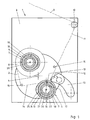
- Fig. 1 shows a front view of a winder 1 with a front wall 2, behind which hide the drive and control elements of the winder 1 substantially.
- a turntable 3 which is driven about a horizontal axis 4 in steps of about 180 °.
- two winding spindles 5 and 6 are provided in opposite arrangement.
- the winding spindle 5 is shown in the operating position, while the winding spindle 6 can be seen in the change position.
- the winding spindles 5 and 6 are separated from each other driven in a clockwise direction and can be stopped.
- Each winding spindle 5, 6 has a relatively elongated axial cylindrical portion, which is suitable and intended for receiving a sleeve 7, on which ultimately a coil 8 is wound or generated. Since Fig. 1 shows the state shortly after further rotation of the turntable 3, the spool 8 is located on the sleeve 7 of the winding spindle 6, while previously it has been wound substantially where now the winding spindle 5 is with its sleeve 7.
- a thread 9 is indicated in dash-dotted lines.
- the thread 9 runs from the top onto a head thread guide 10, which is provided stationary stationary protruding from the front wall 2 of the winder 1 and at which the thread 9 is deflected.
- the thread 9 arrives as an incoming thread 11 to a traversing yarn guide 12 of a thread guide 13.
- successive stroke of the traversing yarn guide is traversed between this and the head thread guide the laying triangle, which denies the incoming thread 11 during the normal spool trip.
- the incoming thread 11 would be wound on the surface of the sleeve 7 to the coil 8.
- the traversing yarn guide 12 is in a position outside the normal laying stroke at such a location that the incoming yarn 11 is in the region of the device for catching the yarn, which is arranged at each freewheeling end of each winding spindle 5, 6 ,
- the running of the winding spindle 5 thread 14 runs over a deflecting device 15 on the periphery of the spool 8 of the winding spindle 6 located in the change position.
- the deflecting device 15 simultaneously prevents the falling thread 14 from falling off the spool 8.
- the device for catching the continuously arriving at a winder 1 yarn 11 is arranged on each winding spindle 5, 6 in the same way at the protruding free end.
- An essential part of this device is a catch bushing 16 with catching slot 17, furthermore a guide bushing 18 with guide slot 19 and a friction bolt 20.
- the friction pin 20 is formed only about finger thick, so has a relatively small outer diameter.
- the catch bush 16 has a much larger inner diameter 21 and know up to its outer diameter 22 a certain material thickness, as it is required for the formation of a solid, resistant to wear body.
- the Fangbuchse 16 as well as the Guide bush 18 may preferably be formed of hard plastic.
- the guide bush 18 surrounds the catch bushing 16, however, only a small distance.
- the guide bush 18 has an inner diameter 24 and an outer diameter 25.
- the outer diameter 25 of the guide bushing 18 is only slightly smaller than the outer diameter of the winding spindle 5 and 6, so that an empty sleeve 7 and a fully wound coil 8 can be up or taken without impairment.
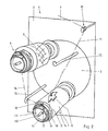
- Fig. 2 shows a perspective view of the conditions in front of the front wall 2 of the winder 1.
- the size relations and the arrangement of the elements to each other better visible.
- the catch bushing 16 and the guide bush 18 are superimposed or not superimposed.
- the part of the device projecting axially furthest from the turntable 3 is the friction pin 20 (see also FIG. 4).
- the catch bushing 16 which is not axially covered over a certain axial length in the region of its cylindrical circumference 26 by the guide bush 18, that is to say extending freely. In this fiausragenden part of the circumference 26 and slightly beyond the catch slot 17 is arranged.
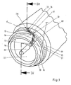
- the cylindrical circumference 26 of the catch bushing 16 is formed by a surface line 27, which thus extends parallel to the axis of the winding spindle 5 and 6 respectively. From Fig. 2 it can be seen that the catching slot 17 is arranged obliquely at a relatively small angle to the surface line 27. This angle 28 is shown in Fig. 3.
- the guide bushing 18 also has a cylindrical circumference 29, which is formed by a generating line 30. The angle 31 between the direction of the guide slot 19 and the generatrix 30 is comparatively larger.
- the guide slot 19 thus extends obliquely as the catching slot 17.
- the guide slot 19 has a base 32 which is sharp-edged, as shown in particular Fig. 3. From Fig.
- the catching slot 17 extends from its open-edge start on the end face 33, starting over the not covered by the guide bush 18 portion of the circumference 26 into a region of the circumference 26, the radia! is covered by the guide bushing 18.
- the catching slot 17 merges directly in the projection into the guide slot 19, as can be seen approximately with reference to FIG. 3.
- the relative position of the catching slot 17 to the guide slot 19 is arbitrary per se, because both the catching bushing 16 as well as the guide bushing 18 rotatably perform their function.
- the catch bushing 16 and the guide bushing 18 rotate together, so they can also be offset by up to 180 ° over the circumference to each other. This is bridged by a piece of thread 11, which hangs on the circumference 26 of the catch bush 16.
- a clamping device 34 is formed or provided between the catch bushing 16 and the guide bush 18.
- An essential part of the clamping device 34 is a ring 35 made of elastic material, for example an O-ring, which is inserted into a groove on the outer circumference 26 of the catch bushing 16 and is in operative contact with the inner circumference corresponding to the inner diameter 24 of the guide bush 18.
- the ring 35 is indicated in Fig. 3 in dashed lines.
- a clamping gap 36 is formed in the region of the guide slot 19, in which the thread 11, 14 sets.
- the clamping device 34 with the clamping gap 36 forms a fixing and tear-off device for the thread, so that on the one hand the incoming thread 11 can form the beginning of a coil 8 on the sleeve 7 of the winding spindle 5, while at the same time the end of the thread 14 on the spool. 8 the sleeve 7 of the winding spindle 6 is wound.
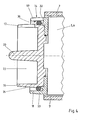
- Fig. 4 shows the overlap of the elements in the axial direction. It is understood that the catch bushing 16 and the guide bushing 18 are permanently attached to the winding spindles 5 and 6 respectively. They are used again for each new sleeve 7. As sleeves 7 can thus normal cylindrical sleeves 7 are used, which have no incision or other special catching device.
Landscapes
- Replacing, Conveying, And Pick-Finding For Filamentary Materials (AREA)
- Storage Of Web-Like Or Filamentary Materials (AREA)
- Spinning Or Twisting Of Yarns (AREA)
- Winding Filamentary Materials (AREA)
- Drilling And Boring (AREA)
Description
- Die vorliegende Erfindung betrifft eine Vorrichtung zum Fangen eines kontinuierlich an einer Spulmaschine mit mindestens zwei Spulspindeln ankommenden Fadens am Anfang einer Spulreise und zum Aufwickeln des Fadens zu einer Spule auf einer auf die Spulspindel aufsetzbaren Hülse, wobei die Vorrichtung eine am freien Ende der Spulspindel angeordnete Fangbuchse mit Fangschlitz und einen im Zentrum der Fangbuchse angeordneten Reibungsbolzen aufweist. Bei einer solchen Vorrichtung geht es darum, einen kontinuierlich erzeugten oder jedenfalls kontinuierlich einer Spulmaschine zulaufenden Faden abgesehen von dem ersten Anlegevorgang kontinuierlich zu Spulen auf Hülsen aufzuwickeln. Die Spulmaschine weist mindestens zwei Spulspindeln auf, um einen automatischen Spulenwechsel zu ermöglichen. In der Regel sind diese beiden Spulspindeln auf einem Drehteller angeordnet und werden abwechselnd in eine Betriebsstellung verschwenkt, während die gerade zuende gewickelte Spule von der sich nicht in der Betriebsstellung befindlichen Spulspindel abgenommen und eine neue Hülse aufgeschoben wird. Für einen automatischen Spulenwechsel ist es erforderlich, den Faden zu durchtrennen. Mit diesem Trennvorgang wird gleichzeitig das Ende des Fadens auf der gerade fertiggewickelten Spule bestimmt. Andererseits wird ein Fadenanfang gebildet, mit dem die Spulreise auf der neuen Hülse beginnt. Dabei kommt es darauf an, den Faden nach Produktionsaufnahme oder nach einer Betriebsunterbrechung erstmals anzulegen. Dies geschieht von Hand, d.h. unter Verwendung einer Absaugpistole. An diesen einmaligen Vorgang schließen sich dann beliebig viele automatische Spulenwechsel an. Der Teil des Fadens, der in der Regel über einen Kopffadenführer einem Fadenleitwerk oder einem Changierfadenführer vor einer sich in der Betriebsstellung befindlichen Spule zuläuft, wird "ankommender Faden" genannt. Der Faden zwischen Fadenleitwerk bzw. Changierfadenführer und der sich im Betrieb befindlichen Spulspindel wird "auflaufender Faden" genannt. Der "ablaufende Faden" ist der Teil des Fadens, der sich zwischen der im Betrieb befindlichen Spulspindel und der nahezu voll bewickelten Spule befindet.
- Eine Vorrichtung der eingangs beschriebenen Art ist aus der Druckschrift der Anmelderin "SAHM 230E 230GE" Nr. 70141-913/3, Ausgabe 10/96, bekannt. Jede Spulspindel weist an ihrem freien Ende eine Vorrichtung zum Fangen des Fadens auf. Diese Vorrichtung besteht im Wesentlichen aus zwei Teilen, nämlich einer Fangbuchse mit Fangschlitz und einem koaxial angeordneten Reibungsbolzen. Bei der Fangbuchse handelt es sich um ein buchsen- oder hülsenförmiges Teil mit einer axialen Länge von einigen Zentimetern. Der Außendurchmesser der Fangbuchse ist gleich oder geringfügig kleiner als der Außendurchmesser der Spulspindel. Der Innendurchmesser der Fangbuchse ist etwas geringer, so dass ein fester beanspruchbarer Körper entsteht, der aber dennoch in der Regel als Kunststoffkörper ausgebildet ist. In der Stirnseite der Fangbuchse beginnt ein Fangschlitz, der schräg zur Mantellinie der Fangbuchse bzw. zur Achse der Spulspindel angeordnet ist. Der Winkel, mit dem der Fangschlitz schräg angeordnet ist, ist relativ groß, d. h. der Fangschlitz ist vergleichsweise steil angeordnet. Der Fangschlitz beginnt an der Stirnseite randoffen und endet randgeschlossen in gewisser axialer Tiefe in der Fangbuchse. Die Fangbuchse ist an der Spulspindel so angeordnet, dass zumindest der axiale Bereich, in dem sich der Fangschlitz erstreckt, von einer ordnungsgemäß aufgeschobenen und festgesetzten Hülse nicht abgedeckt wird. Der Fangschlitz ist abgestimmt auf die Drehrichtung der Spulspindel angeordnet, um einen von der Stirnseite her angenäherten Faden in den Fangschlitz einführen zu können. Im Innern der insoweit hohl ausgebildeten Fangbuchse ist der Reibungsbolzen angeordnet, der einen wesentlich geringeren Außendurchmesser aufweist, als es dem Innendurchmesser der Fangbuchse entspricht. Damit wird zwischen Reibungsbolzen und Fangbuchse ein ringförmiger Freiraum geschaffen, in den das vordere Ende einer Absaugpistole von Hand eingeführt und somit der Faden angelegt werden kann. Der Reibungsbolzen hat die Aufgabe, durch Aufwickeln des Fadens auf ihm bei sich drehender Spulspindel eine gewisse Reibung auf den Faden auszuüben, die dem Erreichen einer Fixierung des Fadens dient. Die Gesamtreibung, die zu einem Fixieren, also einem Festsetzen des Fadens führt, wird darüber hinaus noch von mehreren Einflussgrößen bestimmt, so beispielsweise auch von der Ausbildung des Grundes des Fangschlitzes, in welchem eine Umlenkung des Fadens erfolgt. Ein weiterer Reibungsbestandteil wird von dem Bereich des Fadens erzeugt, der sich unmittelbar nach Eintritt in den Fangschlitz auf dem äußeren Umfang der Fangbuchse bildet.
- Eine solche Vorrichtung ist auch aus der US-A-4 205 800 bekannt.
- Diese bekannte Vorrichtung zum Fangen eines kontinuierlich an einer Spulmaschine ankommenden Fadens lässt nur das manuelle Anlegen mit einer Absaugpistole zu, das bei jeder Spule zu Beginn der Spulreise wiederholt werden muss. Hierzu wird der ankommende Faden von der Absaugpistole abgesaugt, also handhabbar gemacht. Das vordere Ende der Absaugpistole wird in den Freiraum zwischen dem Reibungsbolzen und der Fangbuchse eingeführt. Bei sich drehender Spulspindel erfolgt ein stirnseitiger Kontakt des Fadens an der Fangbuchse, so dass der Faden in den Fangschlitz einlaufen kann. Während dieser Prozedur wird der Faden über die Absaugpistole weiter abgesaugt. Sobald der Faden in den Fangschlitz eingelaufen ist, findet eine Reibungserhöhung an dem Faden statt. Die zunehmende Reibung führt dazu, dass der Faden vermindert rutscht und mit sich verringernder Geschwindigkeit von der Absaugpistole abgesaugt wird. Schließlich wird die Gesamtreibung so groß, dass der Faden relativ zum Fangschlitz stillsteht, also der Faden an der Vorrichtung fixiert ist. Durch das fortgesetzte Aufwickeln auf dem Reibungsbolzen wird noch ein geringer Teil des Fadens aus der Absaugpistole herausgezogen. Durch gleichzeitiges Herausnehmen des vorderen Endes der Absaugpistole aus dem Freiraum besteht die Möglichkeit, den Faden mit einer Schere o. dgl. abzuschneiden. Der Faden läuft dann aufgrund des Verlegedreiecks und/oder der Einwirkung einer Changiereinrichtung auf die Hülse auf, wobei er den Durchmessersprung von dem Außendurchmesser der Fangbuchse auf den Außendurchmesser der Hülse überwindet. Anschließend beginnt dann auf jeden Fall die Spulenwicklung, gegebenenfalls unter Bildung einer vorhergehenden Fixierwicklung, Reservewicklung o. dgl.. Dabei wird der Faden von dem Fadenleitwerk bzw. dem Changierfadenführer entsprechend geführt. Die bekannte Vorrichtung ist insofern bereits vorteilhaft, als sie den Einsatz normaler zylindrischer Hülsen ohne jegliche Fangeinrichtung ermöglicht. Die Vorrichtung zum Fangen befindet sich vielmehr an jeder Spulspindel und steht daher bei jeder Spulenwicklung wieder zur Verfügung. Nachteilig ist, dass die bekannte Vorrichtung lediglich ein Anlegen des Fadens von Hand, d. h. mit einer Absaugpistole, ermöglicht. Ein automatischer Spulenwechsel ist damit nicht möglich.
- Andererseits sind z. B. aus der DE 197 43 278 C2 oder auch der DE 196 46 335 A1 Spezialhülsen bekannt, die mit einem Fangbereich ausgestattet sind. Der Fangbereich kann aus einem über einen Teil des Umfangs der Hülse geführten Einschnitt bestehen, der einen Klemmspalt zum Festsetzen des Fadens bildet. Es ist auch möglich, einen solchen Klemmspalt durch einen stirnseitig an der Hülse angesetzten Einschnitt zu bilden. In Verbindung damit werden kompliziert aufgebaute Changiereinrichtungen mit einer Mehrzahl von Fadenführern eingesetzt, um den Faden relativ zum Klemmspalt, der außerhalb des normalen Changierhubes liegt, zu bringen. Derartige Spezialhülsen lassen vorteilhaft einen automatischen Spulenwechsel zu. Sie erfordern jedoch den Einsatz vergleichsweise teurer Spezialhülsen. Das Fadenleitwerk muss relativ kompliziert gestaltet sein, einschließlich der separaten Antriebe für bis zu drei Fadenführer, die je nach Betriebssituation den Faden übernehmen müssen.
- Aus der DE 196 37 298 A1 ist eine weitere Entwicklungsrichtung einer Fangeinrichtung bekannt. Die Hülse wird hier rechts und links von je einem Zentrierteller gehalten, so dass die Möglichkeit besteht, normale Hülsen einzusetzen. Einer der Zentrierteller ist als Fangeinrichtung in besonderer Weise ausgebildet, d. h. mit Fangnasen besetzt. Die Fangnasen sind auf einem größeren Durchmesser, als es dem Außendurchmesser der Hülse entspricht, angeordnet. Auch hier erfolgt das Fangen des Fadens in Verbindung mit einem Changierfadenführer. Nachteilig an dieser Vorrichtung ist es, dass zu einem Spulenwechsel die beiden Zentrierteller voneinander entfernt werden müssen. Dies macht die Ausbildung und den Antrieb der Zentrierteller aufwändig. Eine solche Fangeinrichtung ist zwar zur automatischen Fadenübergabe geeignet. Sie lässt sich jedoch nicht fest mit einer Spulspindel verbinden, insbesondere nicht mit einer Spulspindel, die ein freies auskragendes Ende aufweist. Ein Aufschieben einer neuen Hülse ist nur dann möglich, wenn die Fangeinrichtung von der Spulspindel temporär entfernt wird.
- Der Erfindung liegt die Aufgabe zugrunde, eine Vorrichtung der eingangs beschriebenen Art so weiterzubilden, dass einerseits das Anlegen des Fadens von Hand, also mit einer Absaugpistole, z. B. nach einer Betriebsunterbrechung, sowie nachfolgend ein automatischer Spulenwechsel bei Einsatz normaler Hülsen ohne Fangbereich möglich wird.
- Erfindungsgemäß wird dies bei einer Vorrichtung der eingangs beschriebenen Art dadurch erreicht, dass an jeder Spulspindel zusätzlich zu der Fangbuchse eine Führungsbuchse mit Führungsschlitz vorgesehen ist, die die Fangbuchse in radialer Richtung umgibt und axial zu der Fangbuchse versetzt angeordnet ist, und dass zwischen der Fangbuchse und der Führungsbuchse eine Klemmeinrichtung zum Fixieren des Fadens bei automatischem Spulenwechsel vorgesehen ist.
- Die neue Vorrichtung bildet die gattungsgemäße Vorrichtung weiter. Sie benutzt die gattungsgemäße Vorrichtung, um die Vorteile des Anlegens von Hand zu realisieren, wie es nach einer Arbeitspause erforderlich wird. Zur Realisierung des automatischen Spulenwechsels ist jedoch der Fangbuchse mit Fangschlitz eine Führungsbuchse mit Führungsschlitz zugeordnet. Die Führungsbuchse besitzt einen größeren Durchmesser als die Fangbuchse und schließt sich - axial in Spulspindelrichtung gesehen - an die Fangbuchse nach innen, also in Richtung auf die zu bildende Spule, an. Die Führungsbuchse weist eine Stirnfläche auf, die axial unter Überdeckung mit dem Fangschlitz der Fangbuchse angeordnet ist. Die Führungsbuchse umgibt somit gleichsam die Fangbuchse in einem kleinen axialen Bereich. Zweckmäßig ist der Außendurchmesser der Führungsbuchse gleich oder kleiner als der Innendurchmesser der verwendeten Hülsen. Die Führungsbuchse weist einen Führungsschlitz auf, der dem Fangschlitz der Fangbuchse zugeordnet ist, so dass zumindest in axialer Richtung ein Anschluss der beiden Schlitze aneinander möglich ist. Da die Vorrichtung bei sich drehender Spulspindel ihre Funktion erfüllt, ist eine Zuordnung des Fangschlitzes zu dem Führungsschlitz in bestimmten Winkelbereichen nicht erforderlich. Freilich muss der Führungsschlitz nach der gleichen Seite schräg zur Mantellinie der Führungsbuchse bzw. zur Achse der Spulspindel angeordnet sein wie der Fangschlitz. Die Fangbuchse und die Führungsbuchse sind zwar auf unterschiedlichen Durchmessern angeordnet, unterscheiden sich jedoch relativ wenig in ihrem Durchmessersprung, während nach wie vor zwischen Fangbuchse und Reibungsbolzen ein großer Durchmessersprung erforderlich ist, wie dies zum manuellen Anlegen des Fadens notwendig ist. Weiterhin ist zwischen Fangbuchse und Führungsbuchse eine Klemmeinrichtung zum Fixieren des Fadens beim automatischen Spulenwechsel vorgesehen. Diese Klemmeinrichtung dient dazu, den Faden zu fixieren, also festzusetzen, so dass er relativ zu dieser Klemmstelle stillsteht. Diese Fixierung wird in zweifacher Hinsicht genutzt. Zum einen dient sie dazu, ein Durchtrennen des Fadens, also des ablaufenden Fadens, auf die nahezu fertig bewickelte Spule zu ermöglichen. In der anderen Richtung wird der Beginn des auflaufenden Fadens gebildet und an der Spulspindel platziert, so dass eine neue Wicklung auf einer neuen Hülse begonnen wird.
- Mit der neuen Vorrichtung lässt sich der erste Anlegevorgang mit Hilfe einer Absaugpistole von Hand wie folgt durchführen:
Der ankommende Faden wird von der Absaugpistole aufgenommen und abgesaugt. Das vordere Ende der Absaugpistole wird in den Freiraum zwischen Reibungsbolzen und Fangbuchse eingeführt. Bei sich drehender Spulspindel findet stirnseitig an der Fangbuchse ein Kontakt zum Faden statt. Der Faden läuft in den Fangschlitz ein. Je nach der relativen Lage des Führungsschlitzes auf der Führungsbuchse ergeben sich zunächst einige wenige Umwicklungen auf dem Umfang der Fangbuchse mit nachfolgendem Übertritt des Fadens in den Führungsschlitz. All dies wird auch ohne Beeinflussung durch ein Fadenleitwerk aufgrund des Verlegedreiecks erreicht, gemäß welchem der Faden immer bestrebt ist, die kürzeste Entfernung einzunehmen. Während dieser Handhabung wird immer noch Faden in die Absaugpistole eingesaugt, d. h. der Faden rutscht an allen Kontaktstellen. Gleichzeitig wird der Faden auch auf den Reibungsbolzen aufgewickelt, da der Fangschlitz den Reibungsbolzen umkreist. Damit steigt die Gesamtreibungskraft auf den Faden an und wird schließlich so groß, dass eine Klemmwirkung eintritt. Diese Gesamtreibungskraft resultiert aus der Umschlingung des Reibungsbolzens mit dem Faden, der Reibung des Fadens im Fangschlitz und ggf. auf dem Umfang der Fangbuchse sowie der Reibung im Führungsschlitz. Mit dem Eintritt der Klemmwirkung und der relativen Fixierung des Fadens zum Führungsschlitz wird der Faden von der Spulspindel bzw. der Vorrichtung übernommen, so dass dann ein Wickelvorgang beginnt. Hierbei wird der Faden von dem Fadenleitwerk bzw. dem Changierfadenführer des Fadenleitwerks übernommen und je nach dem gewünschten Wickelergebnis bewegt, z. B. zunächst mittels einer Fixierwicklung, ggf. einer Reservewicklung, und schließlich im normalen Verlegehub zur Bildung der Spule. Parallel dazu wird der Faden manuell durch einen Schneidevorgang, z. B. mit einer Schere, zwischen Reibungsbolzen und dem vorderen Ende der Absaugpistole durchtrennt. Bei diesem Anlegevorgang übersteigt der Faden auch die Kante der Hülse und den sich dadurch ergebenden Durchmessersprung. Dieser ist jedoch nicht allzu groß gewählt, um den damit verbundenen Sprung in der Fadenspannung beherrschbar zu halten. - Nachdem die erste Spule weitgehend gewickelt worden ist, findet am Ende der Spulreise ein automatischer Spulenwechsel statt. Zu diesem Zweck wird der Drehteller mit den zwei Spulspindeln so gedreht, dass die zweite Spulspindel mit der vorher aufgesetzten normalen Hülse in die Betriebsstellung gelangt, während die Hülse mit der fast fertig gewickelten Spule in die Bereitschaftsstellung gedreht wird. Dabei rutscht der Faden auf dem Umfang der neuen Hülse gemäß den Bewegungen des Changierfadenführers. Der Changierfadenführer wird schließlich so außerhalb des normalen Verlegehubes verfahren, dass der auflaufende Faden in den Bereich und mit dem Umfang der Fangbuchse schleifend in Kontakt kommt. Eine Umlenkeinrichtung, die mit Hilfe eines Umlenkarms oder einer sonstigen gesteuerten Einrichtung arbeitet, verhindert das Herabfallen des Fadens von der vollen Spule. Der ablaufende Faden wird insoweit ordnungsgemäß auf der vollen Spule aufgewickelt. Der auflaufende Faden wird durch den Kontakt mit dem Umfang der Fangbuchse an einem Eintritt in den Fangschlitz gehindert. Dies zielt darauf ab, den Faden nicht mit dem Reibungsbolzen in Kontakt kommen zu lassen, um einen allzu großen Durchmessersprung zu vermeiden, der sich nachteilig auf die Fadenspannung auswirken könnte. Der auflaufende Faden wird insoweit auf dem Umfang der Fangbuchse geführt und läuft allein in den Führungsschlitz der Führungsbuchse ein. Damit ergibt sich eine Richtungs- und Geschwindigkeitsänderung am ablaufenden Faden und in der Folge eine ruckartige Spannungserhöhung. Diese führt dazu, dass der Faden plötzlich in der Klemmeinrichtung zwischen Fangbuchse und Führungsbuchse fixiert wird. Diese Fixierung führt zu einem Abreißen des Fadens, und zwar auch bei sehr zugfestem Fadenmaterial. Durch das Festklemmen des Fadens in der Klemmeinrichtung wird andererseits ein neuer Fadenanfang gebildet und im Bereich der neuen Spulspindel in der Betriebsstellung festgesetzt, so dass ein neuer Wickelvorgang nunmehr automatisch auf der neuen Spulspindel bzw. Hülse beginnen kann. Auch hier kann das Verlegedreieck genutzt werden, um den Faden auf dem Umfang der Führungshülse um einige Wicklungen aufzuwickeln, anschließend die Stirnkante der Hülse zu überschreiten und schließlich in die Mittelstellung des Verlegedreiecks zu gelangen. Diese Bewegungen des Fadens in seitlicher Richtung können durch den Changierfadenführer, durch Bewegungen des Fadenleitwerks und/oder durch axiales Verschieben der Spulspindel erleichtert oder unterstützt werden. Zu Beginn einer Wicklung nach der Fixierung des Fadens können auch hier eine Fixierwicklung, eine Reservewicklung und schließlich die Spule gebildet werden.
- Der Fangschlitz und der Führungsschlitz können in unterschiedlichen Winkeln zu den Mantellinien der Fangbuchse bzw. der Führungsbuchse angeordnet sein. Der führungsschlitz ist steiler als der Fangschlitz angeordnet. Für den Führungsschlitz können Winkel zwischen 45° und 90° zur Mantellinie der Führungsbuchse vorgesehen sein, wobei ein Winkel im Bereich von 80° bevorzugt wird. Der Winkel des Fangschlitzes ist im Bereich zwischen 10° und etwa 60° zur Mantellinie festgelegt. Es ergibt sich auch die Möglichkeit, Fangschlitz und Führungsschlitz in einem gleichen gemittelten Winkel anzuordnen. Wichtig ist dabei, dass der Fangschlitz in einem solchen Winkel schräg zu der Mantellinie der Fangbuchse angeordnet ist, dass bei automatischem Spulenwechsel der Kontakt des ankommenden Fadens mit dem zylindrischen Umfang der Fangbuchse nicht zu einem Eintritt des Fadens in den Fangschlitz, sondern lediglich in den Führungsschlitz, führt. Ein Durchfallen des Fadens bei seinem umfangsmäßigen Kontakt beim automatischen Spulenwechsel bis auf den Durchmesser des Reibungsbolzens würde eine zu große Spannungsänderung im Faden mit entsprechenden nachteiligen Folgen verursachen. Da der Außendurchmesser der Fangbuchse in einem dem Durchmesser der Spulspindel angenäherten Bereich läuft, wird ein allzu großer Spannungssprung am Faden vermieden. Der Fangschlitz kann also mit einem kleineren Winkel als der Führungsschlitz zu der weiligen Mantellinie schräg angeordnet sein.
- Wenn sich der Fangschlitz über den von der Führungsbuchse axial nicht überdeckten Bereich der Fangbuche hinaus bis in den von der Führungsbuchse axial überdeckten Bereich der Fangbuchse erstreckt, besteht die Möglichkeit, dass einerseits der Anschluss zwischen dem Fangschlitz und dem Führungsschlitz beim Anlegen des Fadens von Hand gegeben ist, um die gleiche Ausgangssituation beispielsweise relativ zu einem Changierfadenführer zu erreichen, gleichgültig, ob der Faden von Hand angelegt oder im automatischen Spulenwechsel automatisch angelegt wurde.
- Die Führungsbuchse sollte einen Außendurchmesser aufweisen, der gleich oder kleiner als der die Hülse aufnehmende Durchmesser der Spulspindel ist. Die Führungsbuchse sollte also einen Außendurchmesser aufweisen, der sich vom Außendurchmesser der Spulspindel nicht allzu sehr unterscheidet, jedoch gleichwohl das Abnehmen einer Hülse mit voll bewickelter Spule und das Aufschieben einer neuen Hülse ermöglicht. Auf diese Weise wird auch der Sprung in der Fadenspannung, der sich beim Aufsteigen des Fadens über den Rand der Hülse ergibt, gering gehalten, so dass er ohne weiteres von entsprechenden Regeleinrichtungen, beispielsweise einem Tänzerarm, der Spulmaschine ausgeregelt werden kann.
- Die Klemmeinrichtung ist axial im Bereich des Führungsschlitzes angeordnet. Die Klemmeinrichtung ist damit dem Führungsschlitz so zugeordnet, dass bei Eintritt des Fadens im Führungsschlitz die Klemmeinrichtung zur Einwirkung kommt. Dies gilt insbesondere für den automatischen Spulenwechsel. Beim Anlegen von Hand kann die Klemmeinrichtung zur Einwirkung kommen, sie muss es aber nicht, weil die für das Fixieren des Fadens erforderliche Reibungserhöhung hier auch durch den Reibungsanteil mitbestimmt wird, der von dem Reibungsbolzen aufgebracht wird. Dieser Reibungsanteil steht beim automatischen Spulenwechsel nicht zur Verfügung, so dass hier die Reibungserhöhung durch die Klemmeinrichtung wesentlich ist.
- Für die Realisierung der Klemmeinrichtung ergeben sich verschiedene Möglichkeiten, so kann die Klemmeinrichtung einen Ring aus elastischem Material aufweisen, der mit dem inneren Umfang der Führungsbuchse einen Klemmspalt zum Fixieren des Fadens zwecks Abriss bildet. Bei einem solchen Ring kann es sich in der einfachsten, aber sehr wirksamen Ausführungsform um einen in eine Nut auf dem Umfang der Fangbuchse eingelegten O-Ring handeln, der mit seinem Außenumfang an dem Innenumfang der Führungsbuchse anliegt, so dass hier auf jeden Fall in Verbindung mit dem Führungsschlitz ein Klemmspalt gebildet wird. Es ist aber auch möglich, einen Ring aus federelastischem Metall an dieser Stelle Vorzusehen oder eine sonstige Klemmeinrichtung. Die Klemmeinrichtung muss nur geeignet sein, auf kleinem Raum untergebracht zu werden, wie es der Durchmesserunterschied zwischen Fangbuchse und Führungsbuchse bereitstellt.
- Zusätzlich kann der Grund des Führungsschlitzes scharfkantig ausgebildet sein. Eine solche scharfkantige Ausbildung kann durch eine entsprechende Kantengestaltung realisiert sein. Auch der Einbau eines Messers an dieser Stelle ist möglich. Wichtig ist, dass eine möglichst scharfkantige Umlenkung des Fadens erreicht wird, insbesondere für die Wicklung von Spulen aus hochfestem Spulgut in Faden- oder Bandform.
- Der Durchmesserunterschied zwischen Fangbuchse und Führungsbuchse sollte gering und der Durchmesserunterschied zwischen Fangbuchse und Reibungsbolzen groß sein. Dies ist aus mehreren Gründen sinnvoll. Einerseits wird damit das Anlegen von Hand ermöglicht und der erforderliche Freiraum zwischen Reibungsbolzen und Fangbuchse geschaffen, so dass der Faden mit dem stirnseitigen Bereich der Fangbuchse in Kontakt kommen kann. Andererseits wird durch geringe Durchmesserunterschiede der auftretende Spannungssprung beim Übergang des Fadens von einem Durchmesser auf den anderen gering gehalten.
- Im Folgenden wird die Erfindung anhand in den Figuren dargestellter bevorzugter Ausführungsbeispiele weiter erläutert und beschrieben.
- Fig. 1
- zeigt eine Vorderansicht der Spulmaschine, nachdem die Spulspindel mit der leeren Hülse in Betriebsposition geschwenkt ist, unmittelbar vor dem Zerreißen des Fadens.
- Fig. 2
- zeigt eine perspektivische Darstellung der Spulmaschine gemäß Fig. 1, wobei aus Gründen der Übersichtlichkeit von dem Fadenleitwerk nur der Changierfadenführer dargestellt ist.
- Fig. 3
- zeigt eine Vergrößerung des vorderen freiausragenden Endes der Spulspindel gemäß Fig. 2.
- Fig. 4
- zeigt eine Schnittdarstellung durch die Vorrichtung zum Fangen gemäß der Linie IV - IV in Fig. 3.
- Fig. 1 zeigt eine Vorderansicht auf eine Spulmaschine 1 mit einer Vorderwand 2, hinter der sich im wesentlichen die Antriebs- und Steuerelemente der Spulmaschine 1 verbergen. In der Vorderwand befindet sich ein Drehteller 3, der um eine horizontale Achse 4 in Schritten von etwa 180° antreibbar ist. Auf dem Drehteller 3 sind in gegenüberliegender Anordnung zwei Spulspindeln 5 und 6 vorgesehen. Die Spulspindel 5 ist in der Betriebsstellung dargestellt, während die Spulspindel 6 in der Wechselstellung erkennbar ist. Die Spulspindeln 5 und 6 sind getrennt voneinander im Uhrzeigersinn antreibbar und stillsetzbar.
- Jede Spulspindel 5, 6 besitzt einen relativ langgestalteten axialen zylindrischen Teil, der zur Aufnahme einer Hülse 7 geeignet und bestimmt ist, auf der letztendlich eine Spule 8 aufgewickelt bzw. erzeugt wird. Da Fig. 1 den Zustand kurz nach dem Weiterdrehen des Drehtellers 3 zeigt, befindet sich die Spule 8 auf der Hülse 7 der Spulspindel 6, während sie vorher im wesentlichen dort gewickelt wurde, wo sich nunmehr die Spulspindel 5 mit ihrer Hülse 7 befindet.
- Weiterhin ist ein Faden 9 in strichpunktierter Linienführung angedeutet. Der Faden 9 läuft von oben auf einen Kopffadenführer 10 auf, der ortsfest stillstehend von der Vorderwand 2 der Spulmaschine 1 ausragend vorgesehen ist und an dem der Faden 9 umgelenkt wird. Der Faden 9 gelangt als ankommender Faden 11 zu einem Changierfadenführer 12 eines Fadenleitwerks 13. Durch den senkrecht zur Zeichenebene der Fig. 1 erfolgenden Hub des Changierfadenführers wird zwischen diesem und dem Kopffadenführer das Verlegedreieck durchlaufen, welches der ankommende Faden 11 während der normalen Spulenreise bestreitet. Normalerweise würde der ankommende Faden 11 auf der Oberfläche der Hülse 7 zur Spule 8 aufgewickelt werden. In Fig. 1 befindet sich jedoch der Changierfadenführer 12 in einer Stellung außerhalb des normalen Verlegehubes an einer solchen Stelle, dass der ankommende Faden 11 sich im Bereich der Vorrichtung zum Fangen des Fadens befindet, die an jedem freiausragenden Ende jeder Spulspindel 5, 6 angeordnet ist. Der von der Spulspindel 5 ablaufende Faden 14 läuft über eine Umlenkeinrichtung 15 auf den Umfangder Spule 8 der sich in der Wechselposition befindlichen Spulspindel 6 auf. Die Umlenkeinrichtung 15 verhindert gleichzeitig das Herabfallen des ablaufenden Fadens 14 von der Spule 8.
- Die Vorrichtung zum Fangen des kontinuierlich an einer Spulmaschine 1 ankommenden Fadens 11 ist an jeder Spulspindel 5, 6 in gleicher Weise an dem ausragenden freien Ende angeordnet. Wesentlicher Bestandteil dieser Vorrichtung ist eine Fangbuchse 16 mit Fangschlitz 17, weiterhin eine Führungsbuchse 18 mit Führungsschlitz 19 sowie ein Reibungsbolzen 20. Bereits aus Fig. 1 sind die Durchmesserverhältnisse der Elemente zueinander erkennbar. Der Reibungsbolzen 20 ist nur etwa fingerdick ausgebildet, besitzt also einen relativ kleinen Außendurchmesser. Die Fangbuchse 16 besitzt einen erheblich größeren Innendurchmesser 21 und weißt bis zu ihrem Außendurchmesser 22 eine gewisse Materialstärke auf, wie es für die Ausbildung eines festen, gegen Verschleiß widerstandsfähigen Körpers erforderlich ist. Die Fangbuchse 16 wie auch die Führungsbuchse 18 können bevorzugt aus hartem Kunststoff ausgebildet sein. Aber auch eine Ausbildung aus Metall ist denkbar. Wichtig ist, dass der Innendurchmesser 21 der Fangbuchse 16 erheblich größer als der Außendurchmesser des Reibungsbolzens 20 ist, so dass damit ein ringförmiger Raum 23 geschaffen wird, der so groß ist, dass das vordere Ende einer Absaugpistole zum manuellen Anlegen des Fadens 11 nach einer Betriebsunterbrechung möglich ist.
- Die Führungsbuchse 18 umgibt die Fangbuchse 16 dagegen nur mit geringem Abstand. Die Führungsbuchse 18 weist einen Innendurchmesser 24 und einen Außendurchmesser 25 auf. Der Außendurchmesser 25 der Führungsbuchse 18 ist nur geringfügig kleiner als der Aussendurchmesser der Spulspindel 5 bzw. 6, damit eine leere Hülse 7 bzw. eine vollgewickelte Spule 8 ohne Beeinträchtigung auf- bzw. abgenommen werden können.
- Fig. 2 zeigt in perspektivischer Darstellung die Verhältnisse vor der Vorderwand 2 der Spulmaschine 1. Durch die perspektivische Darstellung werden die Größenrelationen und die Anordnung der Elemente zueinander besser erkennbar. Es ist auch erkennbar, wie und inwieweit sich die Fangbuchse 16 und die Führungsbuchse 18 überlagern bzw. nicht überlagern. Der axial am weitesten von dem Drehteller 3 abstehende Teil der Vorrichtung ist der Reibungsbolzen 20 (s. auch Fig. 4). Danach folgt die Fangbuchse 16, die auf einer gewissen axialen Länge im Bereich ihres zylindrischen Umfangs 26 axial von der Führungsbuchse 18 nicht überdeckt wird, also sich freiausragend erstreckt. In diesem freiausragenden Teil des Umfangs 26 sowie etwas darüber hinaus ist der Fangschlitz 17 angeordnet. Der zylindrische Umfang 26 der Fangbuchse 16 wird von einer Mantellinie 27 gebildet, die sich also parallel zu der Achse der Spulspindel 5 bzw. 6 erstreckt. Aus Fig. 2 ist erkennbar, dass der Fangschlitz 17 in einem relativ kleinen Winkel zu der Mantellinie 27 schrägstehend angeordnet ist. Dieser Winkel 28 ist in Fig. 3 eingezeichnet. Auch die Führungsbuchse 18 weist einen zylindrischen Umfang 29 auf, der von einer Mantellinie 30 gebildet wird. Der Winkel 31 zwischen der Richtung des Führungsschlitzes 19 und der Mantellinie 30 ist vergleichsweise größer. Der Führungsschlitz 19 verläuft also schräger als der Fangschlitz 17. Der Führungsschlitz 19 weist einen Grund 32 auf, der scharfkantig ausgebildet ist, wie dies insbesondere Fig. 3 zeigt. Aus Fig. 3 ist auch erkennbar, dass sich der Fangschlitz 17 von seinem randoffenen Beginn an der Stirnseite 33 ausgehend über den von der Führungsbuchse 18 nicht abgedeckten Teil des Umfangs 26 bis in einen Bereich des Umfangs 26 erstreckt, der radia! von der Führungsbuchse 18 abgedeckt wird. Dagegen Kommt es nicht darauf an, dass der Fangschlitz 17 unmittelbar in der Projektion in den Führungsschlitz 19 übergeht, wie dies angenähert anhand der Fig. 3 erkennbar ist. Die Relativlage des Fangschlitzes 17 zu dem Führungsschlitz 19 ist an sich beliebig, weil sowohl die Fangbuchse 16 wie auch die Führungsbuchse 18 drehend ihre Funktion erbringen. Obwohl die Fangbuchse 16 und die Führungsbuchse 18 gemeinsam drehen, können sie also auch um bis zu 180° über den Umfang versetzt zueinander angeordnet sein. Dies wird durch ein Stück des Fadens 11 überbrückt, welches sich auf dem Umfang 26 der Fangbuchse 16 auflegt.
- Zwischen der Fangbuchse 16 und der Führungsbuchse 18 ist eine Klemmeinrichtung 34 gebildet bzw. vorgesehen. Wesentlicher Bestandteil der Klemmeinrichtung 34 ist ein Ring 35 aus elastischem Material, beispielsweise ein O-Ring, der in eine Nut auf dem äußeren Umfang 26 der Fangbuchse 16 eingelegt ist und mit dem inneren Umfang entsprechend dem Innendurchmesser 24 der Führungsbuchse 18 in Wirkkontakt steht. Der Ring 35 ist in Fig. 3 in gestrichelter Linienführung angedeutet. Zwischen dem Ring 35 und dem inneren Umfang der Führungsbuchse 18 wird im Bereich des Führungsschlitzes 19 ein Klemmspalt 36 gebildet, in welchem sich der Faden 11, 14 festsetzt. Die Klemmeinrichtung 34 mit dem Klemmspalt 36 bildet eine Fixier- und Abreißvorrichtung für den Faden, so dass einerseits der ankommende Faden 11 den Beginn einer Spule 8 auf der Hülse 7 der Spulspindel 5 bilden kann, während gleichzeitig das Ende des Fadens 14 auf der Spule 8 der Hülse 7 der Spulspindel 6 aufgewickelt wird.
- Fig. 4 zeigt die Überdeckung der Elemente in axialer Richtung. Es versteht sich, dass die Fangbuchse 16 und die Führungsbuchse 18 dauerhaft an den Spulspindeln 5 bzw. 6 befestigt sind. Sie kommen für jede neue Hülse 7 wiederum zum Einsatz. Als Hülsen 7 können damit normale zylindrische Hülsen 7 eingesetzt werden, die keinerlei Einschnitt oder sonstige spezielle Fangeinrichtung besitzen.
-
- 01
- Spulmaschine
- 02
- Vorderwand
- 03
- Drehteller
- 04
- Achse
- 05
- Spulspindel
- 06
- Spulspindel
- 07
- Hülse
- 08
- Spule
- 09
- Faden
- 10
- Kopffadenführer
- 21
- Innendurchmesser
- 22
- Außendurchmesser
- 23
- Raum
- 24
- Innendurchmesser
- 25
- Außendurchmesser
- 26
- Umfang
- 27
- Mantellinie
- 28
- Winkel
- 29
- Umfang
- 30
- Mantellinie
- 11
- ankommender Faden
- 12
- Changierfadenführer
- 13
- Fadenleitwerk
- 14
- ablaufender Faden
- 15
- Umlenkeinrichtung
- 16
- Fangbuchse
- 17
- Fangschlitz
- 18
- Führungsbuchse
- 19
- Führungsschlitz
- 20
- Reibungsbolzen
- 31
- Winkel
- 32
- Grund
- 33
- Stirnseite
- 34
- Klemmeinrichtung
- 35
- Ring
- 36
- Klemmspalt
Claims (10)
- Vorrichtung zum Fangen eines kontinuierlich an einer Spulmaschine mit mindestens wei Spulspindeln (5, 6) ankommenden Fadens (11) am Anfang einer Spulreise und zum Aufwickeln des Fadens (11) zu einer Spule (8) auf einer auf die Spulspindel (5, 6) aufsetzbaren Hülse (7), wobei die Vorrichtung eine am freien Ende der Spulspindel (5, 6) angeordnete Fangbuchse (16) mit Fangschlitz (17) und einen im Zentrum der Fangbuchse (16) angeordneten Reibungsbolzen (20) aufweist, dadurch gekennzeichnet, dass an jeder Spulspindel (5, 6) zusätzlich zu der Fangbuchse (16) eine Führungsbuchse (18) mit Führungsschlitz (19) vorgesehen ist, die die Fangbuchse (16) in radialer Richtung umgibt und axial zu der Fangbuchse (16) versetzt angeordnet ist, und dass zwischen der Fangbuchse (16) und der Führungsbuchse (18) eine Klemmeinrichtung (34) zum Fixieren des Fadens (11) bei automatischem Spulenwechsel vorgesehen ist.
- Vorrichtung nach Anspruch 1, dadurch gekennzeichnet, dass der Fangschlitz (17) und der Führungsschlitz (19) in unterschiedlichen Winkeln (28, 31) zu den Mantellinien (27, 0) der Fang buchse (16) bzw. der Führungsbuchse (18) angeordnet sind.
- Vorrichtung nach mindestens einem der Ansprüche 1 bis 2, dadurch gekennzeichnet, dass der Fangschlitz (17) in einem solchen Winkel (28) schräg zu der Mantellinie (27) der Fangbuchse (16) angeordnet ist, dass bei automatischem Spulenwechsel der Kontakt des ankommenden Fadens (11) mit dem zylindrischen Umfang (26) der Fangbuchse (16) nicht zu einem Eintritt des Fadens (11) in den Fangschlitz (1 7), sondern lediglich in den Führungsschlitz (19), führt.
- Vorrichtung nach mindestens einem der Ansprüche 1 bis 3, dadurch gekennzeichnet, dass der Fangschlitz (17) mit einem kleineren Winkel (28) als der Führungsschlitz (19) zu der jeweiligen Mantellinie (27 bzw. 30) schräg angeordnet ist.
- Vorrichtung nach mindestens einem der Ansprüche 1 bis 4, dadurch gekennzeichnet, dass sich der Fangschlitz (17) über den von der Führungsbuchse (18) axial nicht überdeckten Bereich der Fangbuche (16) hinaus bis in den von der Führungsbuchse (18) axial überdeckten Bereich der Fangbuchse (16) erstreckt.
- Vorrichtung nach mindestens einem der Ansprüche 1 bis 5, dadurch gekennzeichnet, dass die Führungsbuchse (18) einen Außendurchmesser (25) aufweist, der gleich oder kleiner als der die Hülse (8) aufnehmende Außendurchmesser der Spulspindel (5, 6) ist.
- Vorrichtung nach Anspruch 1, dadurch gekennzeichnet, dass die Klemmeinrichtung (34) axial im Bereich des Führungsschlitzes (19) angeordnet ist.
- Vorrichtung nach mindestens einem der Ansprüche 1 bis 7, dadurch gekennzeichnet, dass die Klemmeinrichtung (34) einen Ring (35) aus elastischem Material aufweist, der mit dem inneren Umfang der Führungsbuchse (18) einen Klemmspalt (36) zum fixieren des Fadens (11, 14) zwecks Abriss bildet.
- Vorrichtung nach mindestens einem der Ansprüche 1 bis 8, dadurch gekennzeichnet, dass der Grund (32) des Führungsschlitzes (19) scharfkantig ausgebildet ist.
- Vorrichtung nach mindestens einem der Ansprüche 1 bis 9, dadurch gekennzeichnet, dass der Durchmesserunterschied zwischen Fangbuchse (16) und Führungsbuchse (18) gering und der Durchmesserunterschied zwischen Fangbuchse (16) und Reibungsbolzen (20) groß ist.
Applications Claiming Priority (3)
| Application Number | Priority Date | Filing Date | Title |
|---|---|---|---|
| DE10235209 | 2002-08-01 | ||
| DE10235209A DE10235209C1 (de) | 2002-08-01 | 2002-08-01 | Vorrichtung zum Fangen eines Fadens am Anfang einer Spulreise |
| PCT/EP2003/008100 WO2004013028A1 (de) | 2002-08-01 | 2003-07-24 | Vorrichtung zum fangen eines fadens am anfang einer spulreise |
Publications (2)
| Publication Number | Publication Date |
|---|---|
| EP1525150A1 EP1525150A1 (de) | 2005-04-27 |
| EP1525150B1 true EP1525150B1 (de) | 2006-08-30 |
Family
ID=29557874
Family Applications (1)
| Application Number | Title | Priority Date | Filing Date |
|---|---|---|---|
| EP03766270A Expired - Lifetime EP1525150B1 (de) | 2002-08-01 | 2003-07-24 | Vorrichtung zum fangen eines fadens am anfang einer spulreise |
Country Status (8)
| Country | Link |
|---|---|
| EP (1) | EP1525150B1 (de) |
| JP (1) | JP4021895B2 (de) |
| CN (1) | CN1323020C (de) |
| AT (1) | ATE338004T1 (de) |
| DE (2) | DE10235209C1 (de) |
| DK (1) | DK1525150T3 (de) |
| ES (1) | ES2270112T3 (de) |
| WO (1) | WO2004013028A1 (de) |
Cited By (2)
| Publication number | Priority date | Publication date | Assignee | Title |
|---|---|---|---|---|
| US8292211B2 (en) | 2007-08-17 | 2012-10-23 | Lohia Starlinger Limited | Yarn grasping device for automatic yarn transfer in turret type winders |
| DE102012215772B3 (de) * | 2012-09-05 | 2013-12-24 | Georg Sahm Gmbh & Co. Kg | Spulgut-Spreizeinrichtung |
Families Citing this family (3)
| Publication number | Priority date | Publication date | Assignee | Title |
|---|---|---|---|---|
| DE102009033099A1 (de) * | 2009-07-15 | 2011-02-03 | Oerlikon Textile Gmbh & Co. Kg | Spulenhalter |
| DE102016012201A1 (de) | 2016-10-12 | 2018-04-12 | Oerlikon Textile Gmbh & Co. Kg | Aufspulvorrichtung |
| CN108639862B (zh) * | 2018-07-02 | 2023-12-19 | 浙江凯成智能设备股份有限公司 | 一种络筒机的纱线驱动机构 |
Family Cites Families (9)
| Publication number | Priority date | Publication date | Assignee | Title |
|---|---|---|---|---|
| US4208016A (en) * | 1976-03-29 | 1980-06-17 | Owens-Corning Fiberglas Corporation | Method and apparatus for collecting strand |
| US4205800A (en) * | 1977-03-23 | 1980-06-03 | Saint-Gobain Industries | Strand attenuation and winding apparatus |
| DE8414636U1 (de) * | 1984-05-12 | 1985-09-12 | Barmag Barmer Maschinenfabrik Ag, 5630 Remscheid | Spulvorrichtung für Fäden |
| CA1239382A (en) * | 1985-03-29 | 1988-07-19 | Leslie J. Harris | Strand winding apparatus |
| US5460333A (en) * | 1992-07-21 | 1995-10-24 | N.V. Bekaert S.A. | Method apparatus and spool for automated winding |
| DE19646335A1 (de) * | 1995-11-20 | 1997-05-22 | Barmag Barmer Maschf | Spulhülse mit Klemmeinrichtung |
| DE19637298A1 (de) * | 1996-09-13 | 1998-03-19 | Schlafhorst & Co W | Zentrierteller mit Fadenfangkörper zum Fangen eines bereitgehaltenen Fadenendes |
| US6027063A (en) * | 1996-12-20 | 2000-02-22 | Barmag Ag | Takeup machine with threadup device |
| DE19743278C2 (de) * | 1997-09-30 | 1999-10-21 | Sahm Georg Fa | Verfahren und Spulmaschine zum Aufwickeln eines kontinuierlich zulaufenden Fadens zu Spulen |
-
2002
- 2002-08-01 DE DE10235209A patent/DE10235209C1/de not_active Expired - Fee Related
-
2003
- 2003-07-24 JP JP2004525292A patent/JP4021895B2/ja not_active Expired - Lifetime
- 2003-07-24 EP EP03766270A patent/EP1525150B1/de not_active Expired - Lifetime
- 2003-07-24 ES ES03766270T patent/ES2270112T3/es not_active Expired - Lifetime
- 2003-07-24 DK DK03766270T patent/DK1525150T3/da active
- 2003-07-24 CN CNB038185504A patent/CN1323020C/zh not_active Expired - Fee Related
- 2003-07-24 WO PCT/EP2003/008100 patent/WO2004013028A1/de not_active Ceased
- 2003-07-24 AT AT03766270T patent/ATE338004T1/de active
- 2003-07-24 DE DE50304877T patent/DE50304877D1/de not_active Expired - Lifetime
Cited By (3)
| Publication number | Priority date | Publication date | Assignee | Title |
|---|---|---|---|---|
| US8292211B2 (en) | 2007-08-17 | 2012-10-23 | Lohia Starlinger Limited | Yarn grasping device for automatic yarn transfer in turret type winders |
| DE102012215772B3 (de) * | 2012-09-05 | 2013-12-24 | Georg Sahm Gmbh & Co. Kg | Spulgut-Spreizeinrichtung |
| EP2706135A1 (de) | 2012-09-05 | 2014-03-12 | Georg Sahm GmbH & Co. KG | Spulgut-Spreizeinrichtung |
Also Published As
| Publication number | Publication date |
|---|---|
| ES2270112T3 (es) | 2007-04-01 |
| WO2004013028A9 (de) | 2006-06-22 |
| JP4021895B2 (ja) | 2007-12-12 |
| EP1525150A1 (de) | 2005-04-27 |
| CN1675119A (zh) | 2005-09-28 |
| DE10235209C1 (de) | 2003-12-18 |
| WO2004013028A1 (de) | 2004-02-12 |
| JP2005534589A (ja) | 2005-11-17 |
| DE50304877D1 (de) | 2006-10-12 |
| ATE338004T1 (de) | 2006-09-15 |
| CN1323020C (zh) | 2007-06-27 |
| DK1525150T3 (da) | 2007-01-08 |
Similar Documents
| Publication | Publication Date | Title |
|---|---|---|
| DE2615909C2 (de) | ||
| EP2261158B1 (de) | Spulmaschine mit einer Wechseleinrichtung und Verfahren zum Betrieb derselben | |
| DE102019129966B3 (de) | Vorrichtung und Verfahren zum Aufwickeln eines Fadens | |
| EP0937008B1 (de) | Aufspulmaschine | |
| EP1161397A1 (de) | Vorrichtung und verfahren zum führen und schneiden eines zulaufenden fadens beim spulenwechsel | |
| EP0367253B1 (de) | Wechselsystem für eine Fadenpositionierung bei Spulern | |
| DE4434610B4 (de) | Verfahren und Vorrichtung zum Wickeln eines Fadens | |
| EP0916612A2 (de) | Vorrichtung und Verfahren zum Führen und Schneiden eines kontinuierlich zulaufenden Fadens | |
| EP1533261A2 (de) | Vorrichtung und Verfahren zum Aufwickeln nicht zur Verarbeitung vorgesehener Materialstreifen | |
| DE2543986A1 (de) | Verfahren und vorrichtung zur sicherung einer reservewicklung auf einer spulenhuelse | |
| DE2312609A1 (de) | Verfahren und vorrichtung zum auswechseln einer vollen kreuzspule gegen eine leere huelse | |
| EP1525150B1 (de) | Vorrichtung zum fangen eines fadens am anfang einer spulreise | |
| DE2051311C3 (de) | Vorrichtung zur automatischen Verlegung einer Fadenreserve auf eine Spulenhülse außerhalb des Spulbereiches | |
| EP0905077B1 (de) | Spulmaschine und Verfahren zum Aufwickeln eines kontinuierlich zulaufenden Fadens zu Spulen | |
| DE3512403C2 (de) | Fadenendebehandlungseinrichtung | |
| DE102006000824A1 (de) | Fadenspleißvorrichtung für eine Kreuzspulen herstellende Textilmaschine | |
| DE10239334A1 (de) | Fadenspulmaschine mit einem Spannungsdetektor | |
| EP0051222A1 (de) | Vorrichtung zum Einführen von Fäden und dergleichen in eine Spulvorrichtung | |
| DE4334813B4 (de) | Spulvorrichtung | |
| DE4115339B4 (de) | Spulhülse | |
| EP1106556A2 (de) | Vorrichtung zum Schwenken eines Spulenrahmens einer Textilmaschine | |
| DE2614252A1 (de) | Verfahren und vorrichtung zum herstellen einer fadenreserve | |
| DE10016161A1 (de) | Aufspulmaschine | |
| CH631413A5 (de) | Vorrichtung zum aufspulen textiler faeden. | |
| DE4143164C2 (de) | Spulmaschine |
Legal Events
| Date | Code | Title | Description |
|---|---|---|---|
| PUAI | Public reference made under article 153(3) epc to a published international application that has entered the european phase |
Free format text: ORIGINAL CODE: 0009012 |
|
| 17P | Request for examination filed |
Effective date: 20041222 |
|
| AK | Designated contracting states |
Kind code of ref document: A1 Designated state(s): AT BE BG CH CY CZ DE DK EE ES FI FR GB GR HU IE IT LI LU MC NL PT RO SE SI SK TR |
|
| AX | Request for extension of the european patent |
Extension state: AL LT LV MK |
|
| DAX | Request for extension of the european patent (deleted) | ||
| GRAP | Despatch of communication of intention to grant a patent |
Free format text: ORIGINAL CODE: EPIDOSNIGR1 |
|
| GRAS | Grant fee paid |
Free format text: ORIGINAL CODE: EPIDOSNIGR3 |
|
| GRAA | (expected) grant |
Free format text: ORIGINAL CODE: 0009210 |
|
| AK | Designated contracting states |
Kind code of ref document: B1 Designated state(s): AT BE BG CH CY CZ DE DK EE ES FI FR GB GR HU IE IT LI LU MC NL PT RO SE SI SK TR |
|
| PG25 | Lapsed in a contracting state [announced via postgrant information from national office to epo] |
Ref country code: IT Free format text: LAPSE BECAUSE OF FAILURE TO SUBMIT A TRANSLATION OF THE DESCRIPTION OR TO PAY THE FEE WITHIN THE PRESCRIBED TIME-LIMIT;WARNING: LAPSES OF ITALIAN PATENTS WITH EFFECTIVE DATE BEFORE 2007 MAY HAVE OCCURRED AT ANY TIME BEFORE 2007. THE CORRECT EFFECTIVE DATE MAY BE DIFFERENT FROM THE ONE RECORDED. Effective date: 20060830 Ref country code: FI Free format text: LAPSE BECAUSE OF FAILURE TO SUBMIT A TRANSLATION OF THE DESCRIPTION OR TO PAY THE FEE WITHIN THE PRESCRIBED TIME-LIMIT Effective date: 20060830 Ref country code: RO Free format text: LAPSE BECAUSE OF FAILURE TO SUBMIT A TRANSLATION OF THE DESCRIPTION OR TO PAY THE FEE WITHIN THE PRESCRIBED TIME-LIMIT Effective date: 20060830 Ref country code: SK Free format text: LAPSE BECAUSE OF FAILURE TO SUBMIT A TRANSLATION OF THE DESCRIPTION OR TO PAY THE FEE WITHIN THE PRESCRIBED TIME-LIMIT Effective date: 20060830 Ref country code: SI Free format text: LAPSE BECAUSE OF FAILURE TO SUBMIT A TRANSLATION OF THE DESCRIPTION OR TO PAY THE FEE WITHIN THE PRESCRIBED TIME-LIMIT Effective date: 20060830 Ref country code: IE Free format text: LAPSE BECAUSE OF FAILURE TO SUBMIT A TRANSLATION OF THE DESCRIPTION OR TO PAY THE FEE WITHIN THE PRESCRIBED TIME-LIMIT Effective date: 20060830 |
|
| REG | Reference to a national code |
Ref country code: GB Ref legal event code: FG4D Free format text: NOT ENGLISH |
|
| GBT | Gb: translation of ep patent filed (gb section 77(6)(a)/1977) |
Effective date: 20060830 |
|
| REG | Reference to a national code |
Ref country code: CH Ref legal event code: NV Representative=s name: RIEDERER HASLER & PARTNER PATENTANWAELTE AG Ref country code: CH Ref legal event code: EP |
|
| REG | Reference to a national code |
Ref country code: IE Ref legal event code: FG4D Free format text: LANGUAGE OF EP DOCUMENT: GERMAN |
|
| REF | Corresponds to: |
Ref document number: 50304877 Country of ref document: DE Date of ref document: 20061012 Kind code of ref document: P |
|
| PG25 | Lapsed in a contracting state [announced via postgrant information from national office to epo] |
Ref country code: SE Free format text: LAPSE BECAUSE OF FAILURE TO SUBMIT A TRANSLATION OF THE DESCRIPTION OR TO PAY THE FEE WITHIN THE PRESCRIBED TIME-LIMIT Effective date: 20061130 Ref country code: BG Free format text: LAPSE BECAUSE OF FAILURE TO SUBMIT A TRANSLATION OF THE DESCRIPTION OR TO PAY THE FEE WITHIN THE PRESCRIBED TIME-LIMIT Effective date: 20061130 |
|
| REG | Reference to a national code |
Ref country code: DK Ref legal event code: T3 |
|
| PG25 | Lapsed in a contracting state [announced via postgrant information from national office to epo] |
Ref country code: PT Free format text: LAPSE BECAUSE OF FAILURE TO SUBMIT A TRANSLATION OF THE DESCRIPTION OR TO PAY THE FEE WITHIN THE PRESCRIBED TIME-LIMIT Effective date: 20070206 |
|
| ET | Fr: translation filed | ||
| REG | Reference to a national code |
Ref country code: ES Ref legal event code: FG2A Ref document number: 2270112 Country of ref document: ES Kind code of ref document: T3 |
|
| REG | Reference to a national code |
Ref country code: IE Ref legal event code: FD4D |
|
| PLBE | No opposition filed within time limit |
Free format text: ORIGINAL CODE: 0009261 |
|
| STAA | Information on the status of an ep patent application or granted ep patent |
Free format text: STATUS: NO OPPOSITION FILED WITHIN TIME LIMIT |
|
| 26N | No opposition filed |
Effective date: 20070531 |
|
| PG25 | Lapsed in a contracting state [announced via postgrant information from national office to epo] |
Ref country code: GR Free format text: LAPSE BECAUSE OF FAILURE TO SUBMIT A TRANSLATION OF THE DESCRIPTION OR TO PAY THE FEE WITHIN THE PRESCRIBED TIME-LIMIT Effective date: 20061201 Ref country code: MC Free format text: LAPSE BECAUSE OF NON-PAYMENT OF DUE FEES Effective date: 20070731 |
|
| PG25 | Lapsed in a contracting state [announced via postgrant information from national office to epo] |
Ref country code: EE Free format text: LAPSE BECAUSE OF FAILURE TO SUBMIT A TRANSLATION OF THE DESCRIPTION OR TO PAY THE FEE WITHIN THE PRESCRIBED TIME-LIMIT Effective date: 20060830 |
|
| PG25 | Lapsed in a contracting state [announced via postgrant information from national office to epo] |
Ref country code: CY Free format text: LAPSE BECAUSE OF FAILURE TO SUBMIT A TRANSLATION OF THE DESCRIPTION OR TO PAY THE FEE WITHIN THE PRESCRIBED TIME-LIMIT Effective date: 20060830 Ref country code: LU Free format text: LAPSE BECAUSE OF NON-PAYMENT OF DUE FEES Effective date: 20070724 |
|
| PG25 | Lapsed in a contracting state [announced via postgrant information from national office to epo] |
Ref country code: HU Free format text: LAPSE BECAUSE OF FAILURE TO SUBMIT A TRANSLATION OF THE DESCRIPTION OR TO PAY THE FEE WITHIN THE PRESCRIBED TIME-LIMIT Effective date: 20070301 |
|
| PGFP | Annual fee paid to national office [announced via postgrant information from national office to epo] |
Ref country code: DK Payment date: 20110725 Year of fee payment: 9 Ref country code: CH Payment date: 20110725 Year of fee payment: 9 Ref country code: FR Payment date: 20110729 Year of fee payment: 9 |
|
| PGFP | Annual fee paid to national office [announced via postgrant information from national office to epo] |
Ref country code: ES Payment date: 20110728 Year of fee payment: 9 Ref country code: GB Payment date: 20110721 Year of fee payment: 9 |
|
| PGFP | Annual fee paid to national office [announced via postgrant information from national office to epo] |
Ref country code: IT Payment date: 20110727 Year of fee payment: 9 Ref country code: BE Payment date: 20110725 Year of fee payment: 9 Ref country code: NL Payment date: 20110725 Year of fee payment: 9 |
|
| BERE | Be: lapsed |
Owner name: *GEORG SAHM G.M.B.H. & CO. K.G. Effective date: 20120731 |
|
| REG | Reference to a national code |
Ref country code: NL Ref legal event code: V1 Effective date: 20130201 |
|
| REG | Reference to a national code |
Ref country code: CH Ref legal event code: PL |
|
| GBPC | Gb: european patent ceased through non-payment of renewal fee |
Effective date: 20120724 |
|
| REG | Reference to a national code |
Ref country code: DK Ref legal event code: EBP |
|
| REG | Reference to a national code |
Ref country code: FR Ref legal event code: ST Effective date: 20130329 |
|
| PG25 | Lapsed in a contracting state [announced via postgrant information from national office to epo] |
Ref country code: GB Free format text: LAPSE BECAUSE OF NON-PAYMENT OF DUE FEES Effective date: 20120724 Ref country code: LI Free format text: LAPSE BECAUSE OF NON-PAYMENT OF DUE FEES Effective date: 20120731 Ref country code: NL Free format text: LAPSE BECAUSE OF NON-PAYMENT OF DUE FEES Effective date: 20130201 Ref country code: FR Free format text: LAPSE BECAUSE OF NON-PAYMENT OF DUE FEES Effective date: 20120731 Ref country code: CH Free format text: LAPSE BECAUSE OF NON-PAYMENT OF DUE FEES Effective date: 20120731 |
|
| PG25 | Lapsed in a contracting state [announced via postgrant information from national office to epo] |
Ref country code: BE Free format text: LAPSE BECAUSE OF NON-PAYMENT OF DUE FEES Effective date: 20120731 Ref country code: IT Free format text: LAPSE BECAUSE OF NON-PAYMENT OF DUE FEES Effective date: 20120724 |
|
| PG25 | Lapsed in a contracting state [announced via postgrant information from national office to epo] |
Ref country code: DK Free format text: LAPSE BECAUSE OF NON-PAYMENT OF DUE FEES Effective date: 20120731 |
|
| REG | Reference to a national code |
Ref country code: ES Ref legal event code: FD2A Effective date: 20131021 |
|
| PG25 | Lapsed in a contracting state [announced via postgrant information from national office to epo] |
Ref country code: ES Free format text: LAPSE BECAUSE OF NON-PAYMENT OF DUE FEES Effective date: 20120725 |
|
| PGFP | Annual fee paid to national office [announced via postgrant information from national office to epo] |
Ref country code: DE Payment date: 20160714 Year of fee payment: 14 |
|
| PGFP | Annual fee paid to national office [announced via postgrant information from national office to epo] |
Ref country code: CZ Payment date: 20160714 Year of fee payment: 14 Ref country code: AT Payment date: 20160720 Year of fee payment: 14 |
|
| PGFP | Annual fee paid to national office [announced via postgrant information from national office to epo] |
Ref country code: TR Payment date: 20160718 Year of fee payment: 14 |
|
| REG | Reference to a national code |
Ref country code: DE Ref legal event code: R119 Ref document number: 50304877 Country of ref document: DE |
|
| REG | Reference to a national code |
Ref country code: AT Ref legal event code: MM01 Ref document number: 338004 Country of ref document: AT Kind code of ref document: T Effective date: 20170724 |
|
| PG25 | Lapsed in a contracting state [announced via postgrant information from national office to epo] |
Ref country code: CZ Free format text: LAPSE BECAUSE OF NON-PAYMENT OF DUE FEES Effective date: 20170724 Ref country code: DE Free format text: LAPSE BECAUSE OF NON-PAYMENT OF DUE FEES Effective date: 20180201 |
|
| PG25 | Lapsed in a contracting state [announced via postgrant information from national office to epo] |
Ref country code: AT Free format text: LAPSE BECAUSE OF NON-PAYMENT OF DUE FEES Effective date: 20170724 |
|
| PG25 | Lapsed in a contracting state [announced via postgrant information from national office to epo] |
Ref country code: TR Free format text: LAPSE BECAUSE OF NON-PAYMENT OF DUE FEES Effective date: 20170724 |