EP1524930B1 - Einrichtung zum ausleihen von transportwagen - Google Patents
Einrichtung zum ausleihen von transportwagen Download PDFInfo
- Publication number
- EP1524930B1 EP1524930B1 EP03787726A EP03787726A EP1524930B1 EP 1524930 B1 EP1524930 B1 EP 1524930B1 EP 03787726 A EP03787726 A EP 03787726A EP 03787726 A EP03787726 A EP 03787726A EP 1524930 B1 EP1524930 B1 EP 1524930B1
- Authority
- EP
- European Patent Office
- Prior art keywords
- deposit
- trolleys
- collection point
- trolley
- transmitter
- Prior art date
- Legal status (The legal status is an assumption and is not a legal conclusion. Google has not performed a legal analysis and makes no representation as to the accuracy of the status listed.)
- Expired - Lifetime
Links
Images
Classifications
-
- G—PHYSICS
- G07—CHECKING-DEVICES
- G07F—COIN-FREED OR LIKE APPARATUS
- G07F7/00—Mechanisms actuated by objects other than coins to free or to actuate vending, hiring, coin or paper currency dispensing or refunding apparatus
- G07F7/06—Mechanisms actuated by objects other than coins to free or to actuate vending, hiring, coin or paper currency dispensing or refunding apparatus by returnable containers, i.e. reverse vending systems in which a user is rewarded for returning a container that serves as a token of value, e.g. bottles
- G07F7/0618—Mechanisms actuated by objects other than coins to free or to actuate vending, hiring, coin or paper currency dispensing or refunding apparatus by returnable containers, i.e. reverse vending systems in which a user is rewarded for returning a container that serves as a token of value, e.g. bottles by carts
- G07F7/0636—Mechanisms actuated by objects other than coins to free or to actuate vending, hiring, coin or paper currency dispensing or refunding apparatus by returnable containers, i.e. reverse vending systems in which a user is rewarded for returning a container that serves as a token of value, e.g. bottles by carts in which the trolleys or carts are kept in a restricted zone such as a coral-like enclosure, or are passing a gate before use is possible
-
- B—PERFORMING OPERATIONS; TRANSPORTING
- B62—LAND VEHICLES FOR TRAVELLING OTHERWISE THAN ON RAILS
- B62B—HAND-PROPELLED VEHICLES, e.g. HAND CARTS OR PERAMBULATORS; SLEDGES
- B62B3/00—Hand carts having more than one axis carrying transport wheels; Steering devices therefor; Equipment therefor
- B62B3/14—Hand carts having more than one axis carrying transport wheels; Steering devices therefor; Equipment therefor characterised by provisions for nesting or stacking, e.g. shopping trolleys
-
- A—HUMAN NECESSITIES
- A47—FURNITURE; DOMESTIC ARTICLES OR APPLIANCES; COFFEE MILLS; SPICE MILLS; SUCTION CLEANERS IN GENERAL
- A47F—SPECIAL FURNITURE, FITTINGS, OR ACCESSORIES FOR SHOPS, STOREHOUSES, BARS, RESTAURANTS OR THE LIKE; PAYING COUNTERS
- A47F10/00—Furniture or installations specially adapted to particular types of service systems, not otherwise provided for
- A47F10/02—Furniture or installations specially adapted to particular types of service systems, not otherwise provided for for self-service type systems, e.g. supermarkets
- A47F10/04—Furniture or installations specially adapted to particular types of service systems, not otherwise provided for for self-service type systems, e.g. supermarkets for storing or handling self-service hand-carts or baskets
-
- G—PHYSICS
- G07—CHECKING-DEVICES
- G07F—COIN-FREED OR LIKE APPARATUS
- G07F17/00—Coin-freed apparatus for hiring articles; Coin-freed facilities or services
- G07F17/10—Coin-freed apparatus for hiring articles; Coin-freed facilities or services for means for safe-keeping of property, left temporarily, e.g. by fastening the property
Definitions
- the invention relates to a device for borrowing trolleys, each having a equipped with a locking device deposit lock, with a collection point in which the trolleys on deposit basis in at least one row coupled to each other abrat and deducted by payment of a deposit this at least one row, and with a device that acts in the collection area on the locking device of each deposit lock such that only within the collection point the coupling and uncoupling of the trolley is possible.
- DE 43 00 852 A1 describes a device of this type.
- the device of this device is formed by an iron-metallic guide rail on which the equipped with a magnet locking devices of the deposit locks respond. Placed only in the area of the guide rail and very close to it, the deposit locks of the trolley can be operated.
- this device is relatively simple and robust, it still has disadvantages.
- One of these disadvantages is that you must zoom with the trolley very close to the guide rail in order to influence the magnetically acting locking device accordingly.
- Another disadvantage is shown by the fact that you can cling together outside the institution in an undesirable way dolly, if you bring an iron-metallic object side to the deposit lock the car, so that the locking device is caused to deflect or unlock.
- a further disadvantage is that in a self-service market in which several devices of this type are in use, persons after successful shopping preferably visit those devices which are located very close to their own car to the leased transport car just to turn off this nearest facility, although previously the trolleys have been taken from a more distant facility. In such cases, it may happen that you can no longer deliver the leased dolly to the nearest facility because it is already occupied.
- the solution of the problem is that the device has at least one transmitter and the locking device of each deposit lock is equipped with electrically acting control means, which are controlled by the device.
- the transmitter of the device preferably uses the radio and microwave technology. Also ultrasound or infrared technology is suitable. Through the transmitter, the entire space of the device can capture and thus invisibly reach the locking device of each deposit lock, no matter how accurate or inaccurate the trolley are parked in a row. In contrast to the above-mentioned guide rail, a deliberate positioning of the trolley to be able to influence the locking device is not required. By using the transmitter and the pledge lock provided control means, it is also no longer possible outside of the device dolly each other and decouple, since the transmitter is effective only within the device.
- intelligent control means they can be programmed or marked in such a way that only transport trolleys with the same identifier can be parked within a previously defined device in at least one predetermined row and in a predetermined number. This means that a dolly can always be parked only at that facility from which it has been previously removed.
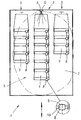
- the drawing shows a plan view of a device 1 with a collection point 2, such as a so-called "park box", through which a space for receiving, for example, designed as a shopping trolley 7 is created.
- a collection point 2 such as a so-called "park box”
- Each trolley 7 is designed in a known manner so that it can save space with the same trolley 7 in a row 3, and pushed together.
- each trolley 7 is equipped with a known deposit lock 8, which has a coupling part and a deposit, so that the trolley 7 decouple from paying the next dolly 7 and return coupled after use, in which case the previously paid deposit refunded again becomes.
- Each deposit lock 8 is equipped with a locking device 9, whose operation will be explained subsequently.
- a device 5 which acts on the locking device 9 of each deposit lock such that only within the collection point 2 a coupling and uncoupling of the trolley 7 on a deposit basis is possible.
- the device 5 is equipped with a transmitter 6, which detects or irradiates a predetermined area 4, indicated by dash-dot lines, within the collection point 2, radio, microwave, ultrasound or infrared light being suitable as "radiation".
- the transmitter 6 detects in the example three rows 3 of trolley 7.
- the locking device 9 of each deposit lock 8 comprises a power source, such as a battery and control means 10 in the form of control electronics, a receiving device for the control electronics and a locking unit, which is capable of the function of the deposit lock 8 to influence.
- Each deposit lock 8 has in a known manner a shaft for receiving the coupling part of the deposit lock 8 of another trolley 7.
- the locking unit is arranged on the shaft and protrudes, for example, with a movable, controllable projection into the shaft when a trolley 7 outside of the device. 1 and thus located outside of the area 4 detected by the transmitter 6. In this situation that can Coupling part of the deposit lock 8 of another trolley 7 are not inserted into the shaft of the deposit lock 8 located outside of the area 4 trolley 7, so that no arrival or decoupling is possible.
- Dolly 7 of the transmitter 6 acts on the control means 10 of the deposit locks 8 such that the locking unit of each deposit lock 8 is released from the shaft of these deposit locks or led out, so that there are located Dolly 7 or dolly Return 7 to the device 1 and leave there parked in rows 3 also coupled.
- the locking unit can also protrude into the coin holder of the deposit lock 8, so that no deposit can be introduced or released. Also in this case is outside the range 4 no arrival or Abkoppelungsvorgang possible.
- the control means 10 are programmable in such a way that only transport trolleys 7 which are programmed the same way, ie have the same identifier, can be disposed of per collection point 2. Accordingly, the transmitter 6 of each collection point 2 must be adapted, for example by changing its frequency. The transmitter 6 for a first collection point 2 thus radiates in a different frequency than the transmitter 6 of another collection point. 2
- more than one device 5, ie at least two transmitters 6, can be provided per device 1. It is also left to the skilled person, as he designed the control electronics, the receiving device for receiving the emitted by the transmitter 6 beams and the blocking unit. In view of the diversity of known deposit locks 8 different design options remain here.
Landscapes
- General Physics & Mathematics (AREA)
- Physics & Mathematics (AREA)
- Engineering & Computer Science (AREA)
- Mechanical Engineering (AREA)
- Combustion & Propulsion (AREA)
- Transportation (AREA)
- Chemical & Material Sciences (AREA)
- Cash Registers Or Receiving Machines (AREA)
- Handcart (AREA)
- Control Of Position, Course, Altitude, Or Attitude Of Moving Bodies (AREA)
- Coin-Freed Apparatuses For Hiring Articles (AREA)
- Management, Administration, Business Operations System, And Electronic Commerce (AREA)
- Control Of Vending Devices And Auxiliary Devices For Vending Devices (AREA)
- Lock And Its Accessories (AREA)
Description
- Die Erfindung betrifft eine Einrichtung zum Ausleihen von Transportwagen, die jeweils ein mit einer Sperreinrichtung ausgestattetes Pfandschloss aufweisen, mit einer Sammelstelle, in der die Transportwagen auf Pfandbasis in mindestens einer Reihe aneinandergekoppelt abstellbar und durch Entrichtung eines Pfandes dieser wenigstens einen Reihe wieder entnehmbar sind, sowie mit einer Vorrichtung, die im Bereich der Sammelstelle auf die Sperreinrichtung eines jeden Pfandschlosses derart einwirkt, dass nur innerhalb der Sammelstelle das An- und Abkoppeln der Transportwagen möglich ist.
- Die DE 43 00 852 A1 beschreibt eine Einrichtung dieser Art. Die Vorrichtung dieser Einrichtung wird durch einen eisenmetallischen Führungsholm gebildet, auf welchen die mit einem Magnet ausgestatteten Sperreinrichtungen der Pfandschlösser reagieren. Nur im Bereich des Führungsholmes und ganz nahe an diesem platziert, lassen sich die Pfandschlösser der Transportwagen bedienen. Obwohl diese Einrichtung relativ einfach und robust aufgebaut ist, besitzt sie dennoch Nachteile. Einer dieser Nachteile besteht darin, dass man mit den Transportwagen ganz nahe an den Führungsholm heranfahren muß, um die magnetisch wirkende Sperreinrichtung entsprechend beeinflussen zu können.
Ein weiterer Nachteil zeigt sich dadurch, dass man außerhalb der Einrichtung in unerwünschter Weise Transportwagen aneinanderkoppeln kann, wenn man an das Pfandschloss der Wagen einen eisenmetallischen Gegenstand seitlich heranführt, so dass die Sperreinrichtung zum Auslenken oder Entsperren veranlasst wird.
Schließlich besteht ein weiterer Nachteil darin, dass in einem SB-Markt, in dem mehrere Einrichtungen dieser Art im Einsatz sind, Personen nach erfolgtem Einkauf bevorzugt jene Einrichtungen aufsuchen, die sich ganz nahe am eigenen Auto befinden, um die ausgeliehenen Transportwagen an eben dieser nächstgelegenen Einrichtung abzustellen, obwohl zuvor die Transportwagen einer weiter entfernten Einrichtung entnommen worden sind. In solchen Fällen kann es vorkommen, dass man den ausgeliehenen Transportwagen nicht mehr an der am nächsten gelegenen Einrichtung abgeben kann, weil diese bereits belegt ist. - Es ist Aufgabe der Erfindung, eine Einrichtung der hier vorliegenden Art so weiterzuentwickeln, dass sich die eben beschriebenen Nachteile vermeiden lassen.
- Die Lösung der Aufgabe besteht darin, dass die Vorrichtung wenigstens einen Sender aufweist und die Sperreinrichtung eines jeden Pfandschlosses mit elektrisch wirkenden Steuermitteln ausgestattet ist, die von der Vorrichtung ansteuerbar sind.
- Der Sender der Vorrichtung bedient sich bevorzugt der Funk- und Mikrowellentechnik. Auch Ultraschall- oder Infrarottechnik ist geeignet. Durch den Sender lässt sich der gesamte Raum der Einrichtung erfassen und damit unsichtbar die Sperreinrichtung eines jeden Pfandschlosses erreichen, ganz gleich, wie genau oder ungenau die Transportwagen in einer Reihe abgestellt sind. Im Gegensatz zum eingangs erwähnten Führungsholm ist eine bewusst vorzunehmende Positionierung der Transportwagen, um die Sperreinrichtung beeinflussen zu können, nicht erforderlich. Durch das Verwenden des Senders und der pro Pfandschloss vorgesehenen Steuermittel ist es auch nicht mehr möglich, außerhalb der Einrichtung Transportwagen gegenseitig an- und abzukoppeln, da der Sender nur innerhalb der Einrichtung wirksam ist. Schließlich lassen sich durch Verwendung elektronischer, also "intelligenter" Steuermittel diese so programmieren oder kennzeichnen, dass nur mit gleicher Kennung ausgetattete Transportwagen innerhalb einer zuvor festgelegten Einrichtung in wenigstens einer vorbestimmten Reihe und in einer vorbestimmten Anzahl abgestellt werden können. Dies bedeutet, dass ein Transportwagen immer nur an jener Einrichtung abgestellt werden kann, aus der er auch zuvor entnommen worden ist.
- Die Erfindung wird anhand einer Prinzipskizze näher erläutert.
- Die Zeichnung zeigt in einer Draufsicht eine Einrichtung 1 mit einer Sammelstelle 2, etwa einer sogenannten "Parkbox", durch die ein Raum zur Aufnahme von beispielsweise als Einkaufswagen gestalteten Transportwagen 7 geschaffen ist. Jeder Transportwagen 7 ist in bekannter Weise so gestaltet, dass er sich mit gleichen Transportwagen 7 in einer Reihe 3 platzsparend, und ineinandergeschoben, abstellen lässt. Ebenso ist jeder Transportwagen 7 mit einem bekannten Pfandschloss 8 ausgestattet, das ein Kopplungsteil und eine Pfandaufnahme aufweist, so dass sich die Transportwagen 7 unter Entrichtung eines Pfandes vom nächsten Transportwagen 7 abkoppeln und nach Gebrauch wieder ankoppeln lassen, wobei dann das zuvor entrichtete Pfand wieder zurückerstattet wird. Jedes Pfandschloss 8 ist mit einer Sperreinrichtung 9 ausgestattet, deren Funktionsweise anschließend erklärt wird. Im Bereich der Sammelstelle 2 ist eine Vorrichtung 5 angeordnet, die auf die Sperreinrichtung 9 eines jeden Pfandschlosses derart einwirkt, dass nur innerhalb der Sammelstelle 2 ein An- und Abkoppeln der Transportwagen 7 auf Pfandbasis möglich ist. Um dies zu erreichen, ist die Vorrichtung 5 mit einem Sender 6 ausgestattet, der eine vorbestimmte Fläche 4, strichpunktiert angedeutet, innerhalb der Sammelstelle 2 erfasst oder bestrahlt, wobei als "Strahlung" Funk, Mikrowelle, Ultraschall oder Infrarotlicht geeignet sind. Der Sender 6 erfasst im Beispiel drei Reihen 3 von Transportwagen 7. Die Sperreinrichtung 9 eines jeden Pfandschlosses 8 umfasst eine Energiequelle, beispielsweise eine Batterie und Steuermittel 10 in Form einer Steuerelektronik, einer Empfangseinrichtung für die Steuerelektronik und einer Sperreinheit, die imstande ist, die Funktion des Pfandschlosses 8 zu beeinflussen. Die elektrisch wirkenden Steuermittel 10 und die Sperreinheit stehen in Wirkverbindung. Jedes Pfandschloss 8 besitzt in bekannter Weise einen Schacht zur Aufnahme des Kopplungsteiles des Pfandschlosses 8 eines weiteren Transportwagens 7. Die Sperreinheit ist am Schacht angeordnet und ragt beispielsweise mit einem beweglichen, ansteuerbaren Vorsprung dann in den Schacht, wenn sich ein Transportwagen 7 außerhalb der Einrichtung 1 und damit außerhalb des vom Sender 6 erfassten Bereiches 4 befindet. In dieser Lage kann das Kopplungsteil des Pfandschlosses 8 eines weiteren Transportwagens 7 nicht in den Schacht des Pfandschlosses 8 eines außerhalb des Bereiches 4 befindlichen Transportwagens 7 eingeführt werden, so dass auch kein An- oder Abkopplungsvorgang möglich ist. Auf alle in der Einrichtung 1 befindlichen Transportwagen 7 wirkt der Sender 6 auf die Steuermittel 10 der Pfandschlösser 8 derart ein, dass die Sperreinheit eines jeden Pfandschlosses 8 vom Schacht dieser Pfandschlösser gelöst oder herausgeführt ist, so dass sich die dort befindlichen Transportwagen 7 ankoppeln oder Transportwagen 7 zur Einrichtung 1 zurückbringen und dort in Reihen 3 abgestellt ebenfalls ankoppeln lassen. Alternativ kann die Sperreinheit auch in die Münzaufnahme des Pfandschlosses 8 ragen, so dass kein Pfand eingeführt oder ausgelöst werden kann. Auch in diesem Falle ist außerhalb des Bereiches 4 kein An- oder Abkoppelungsvorgang möglich. Die Steuermittel 10 sind so programmierbar, dass pro Sammelstelle 2 nur Transportwagen 7 abstellbar sind, die gleich programmiert sind, also die gleiche Kennung besitzen. Entsprechend muß der Sender 6 einer jeden Sammelstelle 2 angepasst sein, beispielsweise durch Veränderung seiner Frequenz. Der Sender 6 für eine erste Sammelstelle 2 strahlt somit in einer anderen Frequenz als der Sender 6 einer weiteren Sammelstelle 2.
- Es bleibt anzumerken, dass pro Einrichtung 1 mehr als nur eine Vorrichtung 5, also mindestens zwei Sender 6 vorgesehen sein können.
Es bleibt ferner dem Fachmann überlassen, wie er die Steuerelektronik, die Empfangseinrichtung zum Empfang der vom Sender 6 ausgesandten Strahlen und die Sperreinheit gestaltet. Angesichts der Verschiedenartigkeit bekannter Pfandschlösser 8 verbleiben hier unterschiedliche Gestaltungsmöglichkeiten.
Claims (2)
- Einrichtung (1) zum Ausleihen von Transportwagen (7), die jeweils ein mit einer Sperreinrichtung (9) ausgestattetes Pfandschloss (8) aufweisen, mit einer Sammelstelle (2), in der die Transportwagen (7) auf Pfandbasis in mindestens einer Reihe (3) aneinandergekoppelt abstellbar und durch Entrichtung eines Pfandes dieser wenigstens einen Reihe (3) wieder entnehmbar sind, sowie mit einer Vorrichtung (5), die im Bereich der Sammelstelle (2) auf die Sperreinrichtung (9) eines jeden Pfandschlosses (8) derart einwirkt, dass nur innerhalb der Sammelstelle (2) das An- und Abkoppeln der Transportwagen (7) möglich ist, dadurch gekennzeichnet, dass die Vorrichtung (5) wenigstens einen Sender (6) aufweist und die Sperreinrichtung (9) eines jeden Pfandschlosses (8) mit elektrisch wirkenden Steuermitteln (10) ausgestattet ist, die von der Vorrichtung (5) ansteuerbar sind.
- Einrichtung nach Anspruch 1, dadurch gekennzeichnet, dass die Steuermittel (10) so programmierbar sind, dass pro Sammelstelle (2) nur solche Transportwagen (7) abstellbar sind, die die gleiche Kennung aufweisen.
Applications Claiming Priority (3)
| Application Number | Priority Date | Filing Date | Title |
|---|---|---|---|
| DE10235727A DE10235727A1 (de) | 2002-08-03 | 2002-08-03 | Einrichtung zum Ausleihen von Transportwagen |
| DE10235727 | 2002-08-03 | ||
| PCT/DE2003/002479 WO2004016138A1 (de) | 2002-08-03 | 2003-07-24 | Einrichtung zum ausleihen von transportwagen |
Publications (2)
| Publication Number | Publication Date |
|---|---|
| EP1524930A1 EP1524930A1 (de) | 2005-04-27 |
| EP1524930B1 true EP1524930B1 (de) | 2006-08-23 |
Family
ID=30469435
Family Applications (1)
| Application Number | Title | Priority Date | Filing Date |
|---|---|---|---|
| EP03787726A Expired - Lifetime EP1524930B1 (de) | 2002-08-03 | 2003-07-24 | Einrichtung zum ausleihen von transportwagen |
Country Status (9)
| Country | Link |
|---|---|
| EP (1) | EP1524930B1 (de) |
| JP (1) | JP2005534454A (de) |
| KR (1) | KR20050026566A (de) |
| CN (1) | CN100401952C (de) |
| AU (1) | AU2003266100A1 (de) |
| DE (2) | DE10235727A1 (de) |
| ES (1) | ES2270147T3 (de) |
| RU (1) | RU2286709C2 (de) |
| WO (1) | WO2004016138A1 (de) |
Families Citing this family (4)
| Publication number | Priority date | Publication date | Assignee | Title |
|---|---|---|---|---|
| DE202005001770U1 (de) * | 2005-02-03 | 2006-06-14 | Sonnendorfer, Horst | Einkaufswagen |
| KR101634446B1 (ko) * | 2014-09-04 | 2016-06-29 | 영남대학교 산학협력단 | 스마트 카트 및 이를 이용한 연결 고리 분리 방법 |
| IL260455B (en) | 2018-07-08 | 2020-05-31 | Freetail Tech Ltd | Device for locking and releasing carts |
| DE102020205766A1 (de) * | 2020-05-07 | 2021-11-11 | Frieder Kolless | Zwischen Münzpfand und digitalem Pfand umschaltbares Münzpfandschloss |
Family Cites Families (18)
| Publication number | Priority date | Publication date | Assignee | Title |
|---|---|---|---|---|
| SU1649581A1 (ru) * | 1989-02-16 | 1991-05-15 | Ворошиловградский машиностроительный институт | Устройство управлени дл камеры хранени |
| US5119087A (en) * | 1989-05-22 | 1992-06-02 | Lucas J Hendren | Shopping cart retrieval system with award signal generation based on a predetermined count |
| DE4200861C2 (de) * | 1992-01-15 | 1996-07-25 | Wolfgang Eberlein | Einrichtung zum Einkaufen von Ware in einem Selbstbedienungsgeschäft oder zum Transport von Reisegepäck |
| EP0598142B1 (de) * | 1992-11-17 | 1996-01-10 | Peter Fuchs | Vorrichtung zur Begrenzung von Einkaufswagenreihen |
| DE4300852A1 (de) * | 1993-01-15 | 1994-07-21 | Wanzl Metallwarenfabrik Kg | Einrichtung zum Ausleihen von Transportwagen |
| DE4319584A1 (de) * | 1993-06-14 | 1994-12-15 | Wanzl Entwicklung Gmbh | Einrichtung zur Aufnahme und Abgabe von Informationen |
| US5921373A (en) * | 1994-09-15 | 1999-07-13 | Smart Carte, Inc. | Cart management system |
| US5526916A (en) * | 1994-09-15 | 1996-06-18 | Smarte Carte, Inc. | Cart management system |
| DE19544484A1 (de) * | 1995-11-29 | 1997-06-05 | Peter Fuchs | Vorrichtung zur Begrenzung von Einkaufswagen-Reihen |
| DE19617205A1 (de) * | 1996-04-30 | 1997-11-13 | Fuchs Peter | Vorrichtung zur Begrenzung von Einkaufswagenreihen |
| DE19719460A1 (de) * | 1997-05-07 | 1998-11-12 | Peter Fuchs | Ordnungssystem für Einkaufswagen |
| ES2184255T3 (es) * | 1997-05-13 | 2003-04-01 | Catena Systems Aps | Sistema que favorece la devolucion de los carros de servicio, carros de supermercado por ejemplo, destinados a transportar articulos en un centro de actividades, centro comercial por ejemplo. |
| DE19720527A1 (de) * | 1997-05-16 | 1998-11-19 | Peter Fuchs | Einkaufswagen-Rückführsystem |
| DE29807344U1 (de) * | 1998-04-24 | 1998-08-06 | Brüder Siegel GmbH & Co. KG Draht- und Metallwarenfabrik, 89340 Leipheim | Selbstbedienungsmarkt |
| DE19915316A1 (de) * | 1999-04-03 | 2000-10-05 | Wanzl Metallwarenfabrik Kg | Einrichtung bestehend aus wenigstens zwei Transportwagen und aus einer Sammelstation |
| DE19956615A1 (de) * | 1999-11-25 | 2001-05-31 | Barbara Jost | Einkaufwagen mit Informationssystem |
| DE10019944A1 (de) * | 2000-04-20 | 2001-10-25 | Systec Pos Technology Gmbh | Verfahren und System zum Erfassen und Belohnen einer Rückführung von Einkaufswagen |
| DE10019942B4 (de) * | 2000-04-20 | 2014-11-27 | Systec Pos-Technology Gmbh | Verfahren und System zum Erfassen und Belohnen der Rückführung von Einkaufswagen |
-
2002
- 2002-08-03 DE DE10235727A patent/DE10235727A1/de not_active Withdrawn
-
2003
- 2003-07-24 CN CNB038175444A patent/CN100401952C/zh not_active Expired - Fee Related
- 2003-07-24 WO PCT/DE2003/002479 patent/WO2004016138A1/de not_active Ceased
- 2003-07-24 DE DE50304769T patent/DE50304769D1/de not_active Expired - Fee Related
- 2003-07-24 AU AU2003266100A patent/AU2003266100A1/en not_active Abandoned
- 2003-07-24 JP JP2004528429A patent/JP2005534454A/ja not_active Withdrawn
- 2003-07-24 ES ES03787726T patent/ES2270147T3/es not_active Expired - Lifetime
- 2003-07-24 EP EP03787726A patent/EP1524930B1/de not_active Expired - Lifetime
- 2003-07-24 RU RU2005105946/12A patent/RU2286709C2/ru not_active IP Right Cessation
- 2003-07-24 KR KR1020057001883A patent/KR20050026566A/ko not_active Withdrawn
Also Published As
| Publication number | Publication date |
|---|---|
| CN100401952C (zh) | 2008-07-16 |
| DE10235727A1 (de) | 2004-02-19 |
| JP2005534454A (ja) | 2005-11-17 |
| RU2005105946A (ru) | 2005-08-10 |
| WO2004016138A1 (de) | 2004-02-26 |
| DE50304769D1 (de) | 2006-10-05 |
| EP1524930A1 (de) | 2005-04-27 |
| KR20050026566A (ko) | 2005-03-15 |
| AU2003266100A1 (en) | 2004-03-03 |
| RU2286709C2 (ru) | 2006-11-10 |
| ES2270147T3 (es) | 2007-04-01 |
| CN1671319A (zh) | 2005-09-21 |
Similar Documents
| Publication | Publication Date | Title |
|---|---|---|
| DE3222445C2 (de) | ||
| EP1307855B1 (de) | Lesevorrichtung mit strichcode-berechtigungskarten | |
| WO2004025579A1 (de) | Rücknahmestation für pfandbelegte oder ausgeliehene objekte | |
| EP1449064B1 (de) | System und verfahren zum erfassen und belohnen der rückführung eines aus einer sammelstelle entnommenen einkaufswagens oder gepäckwagens | |
| DE3830643A1 (de) | Verkehrssteuersystem fuer sich bewegende einrichtungen und/oder menschen | |
| CH695907A5 (de) | Zugangskontrolleinrichtung. | |
| DE10040550A1 (de) | Vorrichtung zur automatischen Erkennung von mit elektronischen Tags versehenen Gepäckstücken | |
| EP1605413B1 (de) | Einrichtung zur Zugangskontrolle | |
| EP1290645B1 (de) | Verfahren und system zum erfassen und belohnen der rückführung von einkaufswagen | |
| EP1524930B1 (de) | Einrichtung zum ausleihen von transportwagen | |
| DE19732597C2 (de) | Rollwagen mit einem Transponder | |
| EP3032501B1 (de) | Verfahren zum Betreiben eines ID-basierten Zugangskontrollsystems | |
| EP3564912B1 (de) | Zugangs- und lesestation | |
| DE4200861A1 (de) | Einrichtung zum einkaufen von ware in einem selbstbedienungsgeschaeft oder zum transport von reisegepaeck | |
| EP0643372B1 (de) | Verfahren und Einrichtung zur Freigabe und Entgegennahme von platzsparend ineinanderschiebbaren Transportwagen | |
| DE19541422A1 (de) | Bereitstellungseinrichtung für Schubgepäckwagen | |
| DE102022125486A1 (de) | Rücknahmevorrichtung für Datenträger | |
| EP1563468A1 (de) | Magazin zum bereitstellen von transportwagen | |
| DE19910454C2 (de) | Chipkartenleser | |
| DE1913347A1 (de) | Einrichtung zum OEffnen eines Durchganges,insbesondere fuer Skilifte | |
| EP1229203A2 (de) | Depositeinrichtung und Depositbehälter | |
| DE102005034521A1 (de) | Verfahren zur Pfandbesicherung von Transportwagen und Pfandsystem | |
| WO2009018921A1 (de) | Fachanlage; verfahren zur identifikation einer person und auswahl von funktionen der fachanlage | |
| DE3304549A1 (de) | Selbstfuellende restgeldeinheit | |
| AT403416B (de) | Kartenförmiger datenträger |
Legal Events
| Date | Code | Title | Description |
|---|---|---|---|
| PUAI | Public reference made under article 153(3) epc to a published international application that has entered the european phase |
Free format text: ORIGINAL CODE: 0009012 |
|
| 17P | Request for examination filed |
Effective date: 20041222 |
|
| AK | Designated contracting states |
Kind code of ref document: A1 Designated state(s): AT BE BG CH CY CZ DE DK EE ES FI FR GB GR HU IE IT LI LU MC NL PT RO SE SI SK TR |
|
| RBV | Designated contracting states (corrected) |
Designated state(s): DE ES FR GB IT |
|
| GRAP | Despatch of communication of intention to grant a patent |
Free format text: ORIGINAL CODE: EPIDOSNIGR1 |
|
| GRAS | Grant fee paid |
Free format text: ORIGINAL CODE: EPIDOSNIGR3 |
|
| GRAA | (expected) grant |
Free format text: ORIGINAL CODE: 0009210 |
|
| AK | Designated contracting states |
Kind code of ref document: B1 Designated state(s): DE ES FR GB IT |
|
| PG25 | Lapsed in a contracting state [announced via postgrant information from national office to epo] |
Ref country code: IT Free format text: LAPSE BECAUSE OF FAILURE TO SUBMIT A TRANSLATION OF THE DESCRIPTION OR TO PAY THE FEE WITHIN THE PRESCRIBED TIME-LIMIT;WARNING: LAPSES OF ITALIAN PATENTS WITH EFFECTIVE DATE BEFORE 2007 MAY HAVE OCCURRED AT ANY TIME BEFORE 2007. THE CORRECT EFFECTIVE DATE MAY BE DIFFERENT FROM THE ONE RECORDED. Effective date: 20060823 |
|
| REG | Reference to a national code |
Ref country code: GB Ref legal event code: FG4D Free format text: NOT ENGLISH |
|
| REF | Corresponds to: |
Ref document number: 50304769 Country of ref document: DE Date of ref document: 20061005 Kind code of ref document: P |
|
| GBT | Gb: translation of ep patent filed (gb section 77(6)(a)/1977) |
Effective date: 20061115 |
|
| ET | Fr: translation filed | ||
| REG | Reference to a national code |
Ref country code: ES Ref legal event code: FG2A Ref document number: 2270147 Country of ref document: ES Kind code of ref document: T3 |
|
| PLBE | No opposition filed within time limit |
Free format text: ORIGINAL CODE: 0009261 |
|
| STAA | Information on the status of an ep patent application or granted ep patent |
Free format text: STATUS: NO OPPOSITION FILED WITHIN TIME LIMIT |
|
| 26N | No opposition filed |
Effective date: 20070524 |
|
| PGFP | Annual fee paid to national office [announced via postgrant information from national office to epo] |
Ref country code: ES Payment date: 20090724 Year of fee payment: 7 Ref country code: FR Payment date: 20090720 Year of fee payment: 7 |
|
| PGFP | Annual fee paid to national office [announced via postgrant information from national office to epo] |
Ref country code: DE Payment date: 20090731 Year of fee payment: 7 Ref country code: GB Payment date: 20090724 Year of fee payment: 7 |
|
| PGFP | Annual fee paid to national office [announced via postgrant information from national office to epo] |
Ref country code: IT Payment date: 20090729 Year of fee payment: 7 |
|
| GBPC | Gb: european patent ceased through non-payment of renewal fee |
Effective date: 20100724 |
|
| REG | Reference to a national code |
Ref country code: FR Ref legal event code: ST Effective date: 20110331 |
|
| PG25 | Lapsed in a contracting state [announced via postgrant information from national office to epo] |
Ref country code: DE Free format text: LAPSE BECAUSE OF NON-PAYMENT OF DUE FEES Effective date: 20110201 |
|
| REG | Reference to a national code |
Ref country code: DE Ref legal event code: R119 Ref document number: 50304769 Country of ref document: DE Effective date: 20110201 |
|
| PG25 | Lapsed in a contracting state [announced via postgrant information from national office to epo] |
Ref country code: FR Free format text: LAPSE BECAUSE OF NON-PAYMENT OF DUE FEES Effective date: 20100802 Ref country code: IT Free format text: LAPSE BECAUSE OF NON-PAYMENT OF DUE FEES Effective date: 20100724 |
|
| PG25 | Lapsed in a contracting state [announced via postgrant information from national office to epo] |
Ref country code: GB Free format text: LAPSE BECAUSE OF NON-PAYMENT OF DUE FEES Effective date: 20100724 |
|
| REG | Reference to a national code |
Ref country code: ES Ref legal event code: FD2A Effective date: 20110818 |
|
| PG25 | Lapsed in a contracting state [announced via postgrant information from national office to epo] |
Ref country code: ES Free format text: LAPSE BECAUSE OF NON-PAYMENT OF DUE FEES Effective date: 20100725 |