EP1524243B1 - Vorrichtung und Verfahren zur Herstellung von hoch schmelzenden Gläsern oder Glaskeramiken sowie Glas oder Glaskeramik - Google Patents
Vorrichtung und Verfahren zur Herstellung von hoch schmelzenden Gläsern oder Glaskeramiken sowie Glas oder Glaskeramik Download PDFInfo
- Publication number
- EP1524243B1 EP1524243B1 EP04105029A EP04105029A EP1524243B1 EP 1524243 B1 EP1524243 B1 EP 1524243B1 EP 04105029 A EP04105029 A EP 04105029A EP 04105029 A EP04105029 A EP 04105029A EP 1524243 B1 EP1524243 B1 EP 1524243B1
- Authority
- EP
- European Patent Office
- Prior art keywords
- glass
- vessel
- iridium
- section
- container
- Prior art date
- Legal status (The legal status is an assumption and is not a legal conclusion. Google has not performed a legal analysis and makes no representation as to the accuracy of the status listed.)
- Expired - Lifetime
Links
- 239000011521 glass Substances 0.000 title claims description 139
- 238000002844 melting Methods 0.000 title claims description 80
- 238000000034 method Methods 0.000 title claims description 39
- 239000002241 glass-ceramic Substances 0.000 title description 37
- 229910052741 iridium Inorganic materials 0.000 claims description 103
- GKOZUEZYRPOHIO-UHFFFAOYSA-N iridium atom Chemical compound [Ir] GKOZUEZYRPOHIO-UHFFFAOYSA-N 0.000 claims description 86
- 239000007789 gas Substances 0.000 claims description 65
- 239000006060 molten glass Substances 0.000 claims description 64
- 239000000463 material Substances 0.000 claims description 57
- 229910045601 alloy Inorganic materials 0.000 claims description 46
- 239000000956 alloy Substances 0.000 claims description 46
- 230000008018 melting Effects 0.000 claims description 45
- 239000000203 mixture Substances 0.000 claims description 43
- 238000010438 heat treatment Methods 0.000 claims description 32
- 230000003647 oxidation Effects 0.000 claims description 32
- 238000007254 oxidation reaction Methods 0.000 claims description 32
- 230000001681 protective effect Effects 0.000 claims description 32
- BASFCYQUMIYNBI-UHFFFAOYSA-N platinum Chemical group [Pt] BASFCYQUMIYNBI-UHFFFAOYSA-N 0.000 claims description 29
- 230000005540 biological transmission Effects 0.000 claims description 26
- 230000006698 induction Effects 0.000 claims description 25
- 238000004519 manufacturing process Methods 0.000 claims description 20
- 238000012545 processing Methods 0.000 claims description 20
- 239000011261 inert gas Substances 0.000 claims description 19
- 229910052760 oxygen Inorganic materials 0.000 claims description 18
- VYPSYNLAJGMNEJ-UHFFFAOYSA-N Silicium dioxide Chemical compound O=[Si]=O VYPSYNLAJGMNEJ-UHFFFAOYSA-N 0.000 claims description 17
- QVGXLLKOCUKJST-UHFFFAOYSA-N atomic oxygen Chemical compound [O] QVGXLLKOCUKJST-UHFFFAOYSA-N 0.000 claims description 16
- 239000001301 oxygen Substances 0.000 claims description 16
- 230000015572 biosynthetic process Effects 0.000 claims description 15
- 239000000395 magnesium oxide Substances 0.000 claims description 15
- CPLXHLVBOLITMK-UHFFFAOYSA-N magnesium oxide Inorganic materials [Mg]=O CPLXHLVBOLITMK-UHFFFAOYSA-N 0.000 claims description 15
- AXZKOIWUVFPNLO-UHFFFAOYSA-N magnesium;oxygen(2-) Chemical compound [O-2].[Mg+2] AXZKOIWUVFPNLO-UHFFFAOYSA-N 0.000 claims description 15
- 230000008569 process Effects 0.000 claims description 15
- 239000011324 bead Substances 0.000 claims description 14
- XLYOFNOQVPJJNP-UHFFFAOYSA-N water Substances O XLYOFNOQVPJJNP-UHFFFAOYSA-N 0.000 claims description 14
- 239000002994 raw material Substances 0.000 claims description 12
- 238000010521 absorption reaction Methods 0.000 claims description 11
- 239000010948 rhodium Substances 0.000 claims description 10
- 238000013461 design Methods 0.000 claims description 8
- 238000003756 stirring Methods 0.000 claims description 8
- KDLHZDBZIXYQEI-UHFFFAOYSA-N Palladium Chemical compound [Pd] KDLHZDBZIXYQEI-UHFFFAOYSA-N 0.000 claims description 7
- 229910001092 metal group alloy Inorganic materials 0.000 claims description 7
- 229910052697 platinum Inorganic materials 0.000 claims description 7
- PNEYBMLMFCGWSK-UHFFFAOYSA-N aluminium oxide Inorganic materials [O-2].[O-2].[O-2].[Al+3].[Al+3] PNEYBMLMFCGWSK-UHFFFAOYSA-N 0.000 claims description 6
- 229910052593 corundum Inorganic materials 0.000 claims description 6
- 230000001105 regulatory effect Effects 0.000 claims description 6
- 239000000377 silicon dioxide Substances 0.000 claims description 6
- 229910001845 yogo sapphire Inorganic materials 0.000 claims description 6
- 229910052703 rhodium Inorganic materials 0.000 claims description 5
- 238000007493 shaping process Methods 0.000 claims description 5
- 239000000758 substrate Substances 0.000 claims description 5
- 229910052681 coesite Inorganic materials 0.000 claims description 4
- 229910052906 cristobalite Inorganic materials 0.000 claims description 4
- 230000007935 neutral effect Effects 0.000 claims description 4
- MHOVAHRLVXNVSD-UHFFFAOYSA-N rhodium atom Chemical compound [Rh] MHOVAHRLVXNVSD-UHFFFAOYSA-N 0.000 claims description 4
- 238000007711 solidification Methods 0.000 claims description 4
- 230000008023 solidification Effects 0.000 claims description 4
- 229910052682 stishovite Inorganic materials 0.000 claims description 4
- 229910052905 tridymite Inorganic materials 0.000 claims description 4
- 239000003513 alkali Substances 0.000 claims description 3
- 229910052792 caesium Inorganic materials 0.000 claims description 3
- 229910052744 lithium Inorganic materials 0.000 claims description 3
- 229910052762 osmium Inorganic materials 0.000 claims description 3
- SYQBFIAQOQZEGI-UHFFFAOYSA-N osmium atom Chemical compound [Os] SYQBFIAQOQZEGI-UHFFFAOYSA-N 0.000 claims description 3
- 229910052763 palladium Inorganic materials 0.000 claims description 3
- 229910052700 potassium Inorganic materials 0.000 claims description 3
- 230000002829 reductive effect Effects 0.000 claims description 3
- 229910052701 rubidium Inorganic materials 0.000 claims description 3
- 229910052708 sodium Inorganic materials 0.000 claims description 3
- KJTLSVCANCCWHF-UHFFFAOYSA-N Ruthenium Chemical compound [Ru] KJTLSVCANCCWHF-UHFFFAOYSA-N 0.000 claims description 2
- 229910052707 ruthenium Inorganic materials 0.000 claims description 2
- MCMNRKCIXSYSNV-UHFFFAOYSA-N Zirconium dioxide Chemical compound O=[Zr]=O MCMNRKCIXSYSNV-UHFFFAOYSA-N 0.000 claims 4
- 239000006112 glass ceramic composition Substances 0.000 claims 4
- 239000008188 pellet Substances 0.000 claims 3
- GWEVSGVZZGPLCZ-UHFFFAOYSA-N Titan oxide Chemical compound O=[Ti]=O GWEVSGVZZGPLCZ-UHFFFAOYSA-N 0.000 claims 2
- JKQOBWVOAYFWKG-UHFFFAOYSA-N molybdenum trioxide Chemical compound O=[Mo](=O)=O JKQOBWVOAYFWKG-UHFFFAOYSA-N 0.000 claims 2
- ZKATWMILCYLAPD-UHFFFAOYSA-N niobium pentoxide Chemical compound O=[Nb](=O)O[Nb](=O)=O ZKATWMILCYLAPD-UHFFFAOYSA-N 0.000 claims 2
- PBCFLUZVCVVTBY-UHFFFAOYSA-N tantalum pentoxide Inorganic materials O=[Ta](=O)O[Ta](=O)=O PBCFLUZVCVVTBY-UHFFFAOYSA-N 0.000 claims 1
- ZNOKGRXACCSDPY-UHFFFAOYSA-N tungsten(VI) oxide Inorganic materials O=[W](=O)=O ZNOKGRXACCSDPY-UHFFFAOYSA-N 0.000 claims 1
- 239000000156 glass melt Substances 0.000 description 38
- 238000007670 refining Methods 0.000 description 24
- 230000007704 transition Effects 0.000 description 14
- 229910018072 Al 2 O 3 Inorganic materials 0.000 description 13
- XKRFYHLGVUSROY-UHFFFAOYSA-N Argon Chemical compound [Ar] XKRFYHLGVUSROY-UHFFFAOYSA-N 0.000 description 12
- 230000003595 spectral effect Effects 0.000 description 12
- 239000002826 coolant Substances 0.000 description 10
- 229910000510 noble metal Inorganic materials 0.000 description 10
- 230000009467 reduction Effects 0.000 description 10
- 229910004298 SiO 2 Inorganic materials 0.000 description 9
- IJGRMHOSHXDMSA-UHFFFAOYSA-N Atomic nitrogen Chemical compound N#N IJGRMHOSHXDMSA-UHFFFAOYSA-N 0.000 description 8
- 239000013078 crystal Substances 0.000 description 8
- 229910052751 metal Inorganic materials 0.000 description 8
- 239000002184 metal Substances 0.000 description 8
- 238000000465 moulding Methods 0.000 description 8
- 230000002093 peripheral effect Effects 0.000 description 8
- 230000000694 effects Effects 0.000 description 7
- 230000001965 increasing effect Effects 0.000 description 7
- 238000009413 insulation Methods 0.000 description 7
- 229910000575 Ir alloy Inorganic materials 0.000 description 6
- 229910052786 argon Inorganic materials 0.000 description 6
- 239000000835 fiber Substances 0.000 description 5
- 239000001257 hydrogen Substances 0.000 description 5
- 229910052739 hydrogen Inorganic materials 0.000 description 5
- 229910052750 molybdenum Inorganic materials 0.000 description 5
- 239000010970 precious metal Substances 0.000 description 5
- 239000007787 solid Substances 0.000 description 5
- UFHFLCQGNIYNRP-UHFFFAOYSA-N Hydrogen Chemical compound [H][H] UFHFLCQGNIYNRP-UHFFFAOYSA-N 0.000 description 4
- ZOKXTWBITQBERF-UHFFFAOYSA-N Molybdenum Chemical compound [Mo] ZOKXTWBITQBERF-UHFFFAOYSA-N 0.000 description 4
- 229910001260 Pt alloy Inorganic materials 0.000 description 4
- 229910006404 SnO 2 Inorganic materials 0.000 description 4
- 238000009529 body temperature measurement Methods 0.000 description 4
- 239000011449 brick Substances 0.000 description 4
- 229910052878 cordierite Inorganic materials 0.000 description 4
- JSKIRARMQDRGJZ-UHFFFAOYSA-N dimagnesium dioxido-bis[(1-oxido-3-oxo-2,4,6,8,9-pentaoxa-1,3-disila-5,7-dialuminabicyclo[3.3.1]nonan-7-yl)oxy]silane Chemical compound [Mg++].[Mg++].[O-][Si]([O-])(O[Al]1O[Al]2O[Si](=O)O[Si]([O-])(O1)O2)O[Al]1O[Al]2O[Si](=O)O[Si]([O-])(O1)O2 JSKIRARMQDRGJZ-UHFFFAOYSA-N 0.000 description 4
- 238000002845 discoloration Methods 0.000 description 4
- 238000002474 experimental method Methods 0.000 description 4
- 239000011733 molybdenum Substances 0.000 description 4
- 229910052757 nitrogen Inorganic materials 0.000 description 4
- 230000003287 optical effect Effects 0.000 description 4
- 229910052721 tungsten Inorganic materials 0.000 description 4
- 238000003466 welding Methods 0.000 description 4
- 229910019017 PtRh Inorganic materials 0.000 description 3
- 229910010413 TiO 2 Inorganic materials 0.000 description 3
- GEIAQOFPUVMAGM-UHFFFAOYSA-N ZrO Inorganic materials [Zr]=O GEIAQOFPUVMAGM-UHFFFAOYSA-N 0.000 description 3
- 229910000272 alkali metal oxide Inorganic materials 0.000 description 3
- 238000005266 casting Methods 0.000 description 3
- 239000000919 ceramic Substances 0.000 description 3
- 229910010293 ceramic material Inorganic materials 0.000 description 3
- 239000003795 chemical substances by application Substances 0.000 description 3
- 230000004927 fusion Effects 0.000 description 3
- 239000006066 glass batch Substances 0.000 description 3
- 238000011068 loading method Methods 0.000 description 3
- 239000000155 melt Substances 0.000 description 3
- 239000000047 product Substances 0.000 description 3
- 238000010926 purge Methods 0.000 description 3
- 239000011819 refractory material Substances 0.000 description 3
- WFKWXMTUELFFGS-UHFFFAOYSA-N tungsten Chemical compound [W] WFKWXMTUELFFGS-UHFFFAOYSA-N 0.000 description 3
- 239000010937 tungsten Substances 0.000 description 3
- 229910000979 O alloy Inorganic materials 0.000 description 2
- 238000005275 alloying Methods 0.000 description 2
- 230000008901 benefit Effects 0.000 description 2
- 238000006243 chemical reaction Methods 0.000 description 2
- 150000001875 compounds Chemical class 0.000 description 2
- 238000010276 construction Methods 0.000 description 2
- 238000005336 cracking Methods 0.000 description 2
- 238000002425 crystallisation Methods 0.000 description 2
- 230000008025 crystallization Effects 0.000 description 2
- 239000008367 deionised water Substances 0.000 description 2
- 230000001419 dependent effect Effects 0.000 description 2
- KZHJGOXRZJKJNY-UHFFFAOYSA-N dioxosilane;oxo(oxoalumanyloxy)alumane Chemical compound O=[Si]=O.O=[Si]=O.O=[Al]O[Al]=O.O=[Al]O[Al]=O.O=[Al]O[Al]=O KZHJGOXRZJKJNY-UHFFFAOYSA-N 0.000 description 2
- 235000013312 flour Nutrition 0.000 description 2
- 230000002706 hydrostatic effect Effects 0.000 description 2
- 238000009434 installation Methods 0.000 description 2
- 230000003993 interaction Effects 0.000 description 2
- 230000001788 irregular Effects 0.000 description 2
- 230000007774 longterm Effects 0.000 description 2
- 238000010309 melting process Methods 0.000 description 2
- 238000002156 mixing Methods 0.000 description 2
- 229910052863 mullite Inorganic materials 0.000 description 2
- 239000013307 optical fiber Substances 0.000 description 2
- 230000001590 oxidative effect Effects 0.000 description 2
- 230000036961 partial effect Effects 0.000 description 2
- 229910052573 porcelain Inorganic materials 0.000 description 2
- 239000011148 porous material Substances 0.000 description 2
- 230000005855 radiation Effects 0.000 description 2
- 238000012216 screening Methods 0.000 description 2
- 239000010935 stainless steel Substances 0.000 description 2
- 229910001220 stainless steel Inorganic materials 0.000 description 2
- 239000004575 stone Substances 0.000 description 2
- 230000035882 stress Effects 0.000 description 2
- 230000008093 supporting effect Effects 0.000 description 2
- XOLBLPGZBRYERU-UHFFFAOYSA-N tin dioxide Chemical compound O=[Sn]=O XOLBLPGZBRYERU-UHFFFAOYSA-N 0.000 description 2
- 238000005303 weighing Methods 0.000 description 2
- 101150108975 Rhd gene Proteins 0.000 description 1
- 238000003723 Smelting Methods 0.000 description 1
- 229910006501 ZrSiO Inorganic materials 0.000 description 1
- 230000001133 acceleration Effects 0.000 description 1
- 230000009471 action Effects 0.000 description 1
- 230000006978 adaptation Effects 0.000 description 1
- 239000000654 additive Substances 0.000 description 1
- 229910052782 aluminium Inorganic materials 0.000 description 1
- WNROFYMDJYEPJX-UHFFFAOYSA-K aluminium hydroxide Chemical compound [OH-].[OH-].[OH-].[Al+3] WNROFYMDJYEPJX-UHFFFAOYSA-K 0.000 description 1
- MHCAFGMQMCSRGH-UHFFFAOYSA-N aluminum;hydrate Chemical compound O.[Al] MHCAFGMQMCSRGH-UHFFFAOYSA-N 0.000 description 1
- 229910052785 arsenic Inorganic materials 0.000 description 1
- 239000005391 art glass Substances 0.000 description 1
- 238000007664 blowing Methods 0.000 description 1
- KGBXLFKZBHKPEV-UHFFFAOYSA-N boric acid Chemical compound OB(O)O KGBXLFKZBHKPEV-UHFFFAOYSA-N 0.000 description 1
- 239000004327 boric acid Substances 0.000 description 1
- 239000012876 carrier material Substances 0.000 description 1
- 238000001311 chemical methods and process Methods 0.000 description 1
- 239000007795 chemical reaction product Substances 0.000 description 1
- 229910052804 chromium Inorganic materials 0.000 description 1
- 238000005253 cladding Methods 0.000 description 1
- 238000011109 contamination Methods 0.000 description 1
- 238000010924 continuous production Methods 0.000 description 1
- 230000001276 controlling effect Effects 0.000 description 1
- 238000007796 conventional method Methods 0.000 description 1
- 238000001816 cooling Methods 0.000 description 1
- 229910052802 copper Inorganic materials 0.000 description 1
- 230000007797 corrosion Effects 0.000 description 1
- 238000005260 corrosion Methods 0.000 description 1
- 230000003247 decreasing effect Effects 0.000 description 1
- 230000001066 destructive effect Effects 0.000 description 1
- 238000007599 discharging Methods 0.000 description 1
- 238000001035 drying Methods 0.000 description 1
- 230000008020 evaporation Effects 0.000 description 1
- 238000001704 evaporation Methods 0.000 description 1
- 230000002349 favourable effect Effects 0.000 description 1
- 239000002657 fibrous material Substances 0.000 description 1
- 239000012530 fluid Substances 0.000 description 1
- 235000013305 food Nutrition 0.000 description 1
- 239000010440 gypsum Substances 0.000 description 1
- 229910052602 gypsum Inorganic materials 0.000 description 1
- 239000001307 helium Substances 0.000 description 1
- 229910052734 helium Inorganic materials 0.000 description 1
- SWQJXJOGLNCZEY-UHFFFAOYSA-N helium atom Chemical compound [He] SWQJXJOGLNCZEY-UHFFFAOYSA-N 0.000 description 1
- 150000002431 hydrogen Chemical class 0.000 description 1
- 239000012535 impurity Substances 0.000 description 1
- 230000001939 inductive effect Effects 0.000 description 1
- 239000003999 initiator Substances 0.000 description 1
- 238000002347 injection Methods 0.000 description 1
- 239000007924 injection Substances 0.000 description 1
- 238000003780 insertion Methods 0.000 description 1
- 230000037431 insertion Effects 0.000 description 1
- 230000002262 irrigation Effects 0.000 description 1
- 238000003973 irrigation Methods 0.000 description 1
- 238000005304 joining Methods 0.000 description 1
- 229910052745 lead Inorganic materials 0.000 description 1
- 229910052749 magnesium Inorganic materials 0.000 description 1
- 239000011777 magnesium Substances 0.000 description 1
- ZLNQQNXFFQJAID-UHFFFAOYSA-L magnesium carbonate Chemical compound [Mg+2].[O-]C([O-])=O ZLNQQNXFFQJAID-UHFFFAOYSA-L 0.000 description 1
- 239000001095 magnesium carbonate Substances 0.000 description 1
- 229910000021 magnesium carbonate Inorganic materials 0.000 description 1
- 238000012423 maintenance Methods 0.000 description 1
- 230000014759 maintenance of location Effects 0.000 description 1
- 229910052748 manganese Inorganic materials 0.000 description 1
- 150000002739 metals Chemical class 0.000 description 1
- 238000012544 monitoring process Methods 0.000 description 1
- 231100000252 nontoxic Toxicity 0.000 description 1
- 230000003000 nontoxic effect Effects 0.000 description 1
- 238000013021 overheating Methods 0.000 description 1
- 230000035515 penetration Effects 0.000 description 1
- 239000005365 phosphate glass Substances 0.000 description 1
- 238000012805 post-processing Methods 0.000 description 1
- 235000019353 potassium silicate Nutrition 0.000 description 1
- 239000000843 powder Substances 0.000 description 1
- 229910052702 rhenium Inorganic materials 0.000 description 1
- WUAPFZMCVAUBPE-UHFFFAOYSA-N rhenium atom Chemical compound [Re] WUAPFZMCVAUBPE-UHFFFAOYSA-N 0.000 description 1
- 238000005096 rolling process Methods 0.000 description 1
- 229910052594 sapphire Inorganic materials 0.000 description 1
- 239000010980 sapphire Substances 0.000 description 1
- 238000007789 sealing Methods 0.000 description 1
- 235000012239 silicon dioxide Nutrition 0.000 description 1
- 229910052709 silver Inorganic materials 0.000 description 1
- 230000000087 stabilizing effect Effects 0.000 description 1
- 239000007858 starting material Substances 0.000 description 1
- 230000003068 static effect Effects 0.000 description 1
- 239000003351 stiffener Substances 0.000 description 1
- 230000008646 thermal stress Effects 0.000 description 1
- 230000001960 triggered effect Effects 0.000 description 1
- 229910052720 vanadium Inorganic materials 0.000 description 1
- 229910052725 zinc Inorganic materials 0.000 description 1
Images

Classifications
-
- C—CHEMISTRY; METALLURGY
- C03—GLASS; MINERAL OR SLAG WOOL
- C03B—MANUFACTURE, SHAPING, OR SUPPLEMENTARY PROCESSES
- C03B5/00—Melting in furnaces; Furnaces so far as specially adapted for glass manufacture
- C03B5/02—Melting in furnaces; Furnaces so far as specially adapted for glass manufacture in electric furnaces, e.g. by dielectric heating
- C03B5/021—Melting in furnaces; Furnaces so far as specially adapted for glass manufacture in electric furnaces, e.g. by dielectric heating by induction heating
-
- C—CHEMISTRY; METALLURGY
- C03—GLASS; MINERAL OR SLAG WOOL
- C03B—MANUFACTURE, SHAPING, OR SUPPLEMENTARY PROCESSES
- C03B5/00—Melting in furnaces; Furnaces so far as specially adapted for glass manufacture
- C03B5/16—Special features of the melting process; Auxiliary means specially adapted for glass-melting furnaces
- C03B5/167—Means for preventing damage to equipment, e.g. by molten glass, hot gases, batches
- C03B5/1672—Use of materials therefor
- C03B5/1675—Platinum group metals
-
- C—CHEMISTRY; METALLURGY
- C03—GLASS; MINERAL OR SLAG WOOL
- C03B—MANUFACTURE, SHAPING, OR SUPPLEMENTARY PROCESSES
- C03B5/00—Melting in furnaces; Furnaces so far as specially adapted for glass manufacture
- C03B5/16—Special features of the melting process; Auxiliary means specially adapted for glass-melting furnaces
- C03B5/26—Outlets, e.g. drains, siphons; Overflows, e.g. for supplying the float tank, tweels
-
- C—CHEMISTRY; METALLURGY
- C03—GLASS; MINERAL OR SLAG WOOL
- C03C—CHEMICAL COMPOSITION OF GLASSES, GLAZES OR VITREOUS ENAMELS; SURFACE TREATMENT OF GLASS; SURFACE TREATMENT OF FIBRES OR FILAMENTS MADE FROM GLASS, MINERALS OR SLAGS; JOINING GLASS TO GLASS OR OTHER MATERIALS
- C03C3/00—Glass compositions
- C03C3/04—Glass compositions containing silica
- C03C3/076—Glass compositions containing silica with 40% to 90% silica, by weight
- C03C3/083—Glass compositions containing silica with 40% to 90% silica, by weight containing aluminium oxide or an iron compound
- C03C3/085—Glass compositions containing silica with 40% to 90% silica, by weight containing aluminium oxide or an iron compound containing an oxide of a divalent metal
-
- C—CHEMISTRY; METALLURGY
- C03—GLASS; MINERAL OR SLAG WOOL
- C03C—CHEMICAL COMPOSITION OF GLASSES, GLAZES OR VITREOUS ENAMELS; SURFACE TREATMENT OF GLASS; SURFACE TREATMENT OF FIBRES OR FILAMENTS MADE FROM GLASS, MINERALS OR SLAGS; JOINING GLASS TO GLASS OR OTHER MATERIALS
- C03C3/00—Glass compositions
- C03C3/04—Glass compositions containing silica
- C03C3/076—Glass compositions containing silica with 40% to 90% silica, by weight
- C03C3/089—Glass compositions containing silica with 40% to 90% silica, by weight containing boron
- C03C3/091—Glass compositions containing silica with 40% to 90% silica, by weight containing boron containing aluminium
-
- Y—GENERAL TAGGING OF NEW TECHNOLOGICAL DEVELOPMENTS; GENERAL TAGGING OF CROSS-SECTIONAL TECHNOLOGIES SPANNING OVER SEVERAL SECTIONS OF THE IPC; TECHNICAL SUBJECTS COVERED BY FORMER USPC CROSS-REFERENCE ART COLLECTIONS [XRACs] AND DIGESTS
- Y02—TECHNOLOGIES OR APPLICATIONS FOR MITIGATION OR ADAPTATION AGAINST CLIMATE CHANGE
- Y02P—CLIMATE CHANGE MITIGATION TECHNOLOGIES IN THE PRODUCTION OR PROCESSING OF GOODS
- Y02P40/00—Technologies relating to the processing of minerals
- Y02P40/50—Glass production, e.g. reusing waste heat during processing or shaping
- Y02P40/57—Improving the yield, e-g- reduction of reject rates
Definitions
- the present invention relates to an apparatus and a method for producing high-melting glasses or glass-ceramics. More particularly, the present invention relates to an apparatus and a method for producing shaped articles, for example rods or other solid bodies, as well as pipes or other hollow bodies, from high-melting glasses or glass ceramics in discontinuous operation. Furthermore, the present invention relates to a high-melting glass or a high-melting glass ceramic and moldings produced therefrom.
- the present invention relates to glasses or glass ceramics which have only a very small proportion of network converters, in particular alkali oxides, and glasses or glass ceramics containing a high proportion of high-melting oxides such as SiO 2 , Al 2 O 3 , ZrO 2 , Nb 2 O 5 or Ta 2 O 5 , have.
- Glasses or glass ceramics of the aforementioned type have relatively high melting temperatures in the range of about 1700 ° C.
- a molten glass often has to be heated for relatively long periods of time to relatively high temperatures, for example for refining the molten glass.
- the necessary relatively high temperatures in continuous operation pose new challenges for the design of crucibles.
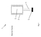
- the Fig. 1 shows an apparatus for producing tubes and rods in discontinuous operation according to the prior art.
- the device comprises a crucible 2 serving as a melting vessel, which is usually formed from Pt and Pt alloys, for example PtRh30.
- the crucible 2 has a cylindrical shape and has a likewise made of precious metal bottom in which the glass batch or broken glass is first melted and then at about 50-100 ° C higher temperature is purified.
- a heating device 3 is arranged around the crucible 2 around. Usually, the heating is inductive, but it can also be designed as a direct or indirect resistance heating.
- the crucible 2 is usually closed by a cover (not shown) formed of a refractory material or a precious metal to ensure sufficient heat to avoid large temperature gradients.
- a cover (not shown) formed of a refractory material or a precious metal to ensure sufficient heat to avoid large temperature gradients.
- the processes described smelting and refining run faster and thus more cost-effectively, the higher the selected temperature level.
- the molten glass with the help of a Precious metal stirrer, for example made of the aforementioned Pt alloys or pure platinum, are stirred.
- a tube 4 made of one of the aforementioned noble metals is welded under the crucible 2, which is heated via one or more of the crucible heater 2 independent heating circuits. This ensures that the temperature setting of the tube 4 which determines the hot forming process can be realized independently of the temperature setting of the crucible 2
- the device according to the Fig. 1 is usually operated sequentially in the two operating states described below.
- a first operating state the tube 4 is initially kept relatively cold for melting and refining the molten glass, so that just melted in the crucible 2 glass does not immediately run out of the crucible.
- Glass melt which runs into the tube 4 at the bottom of the crucible 2, solidifies or solidifies in the tube 4 to a plug which clogs the tube 4 sufficiently to prevent leakage of the molten glass.
- the temperature is lowered in a second operating state in the crucible 2 and increased in the tube 4 until a favorable for the hot forming viscosity profile for the entire arrangement results.
- the temperature in the crucible 2 and in the tube 4 is then usually in the vicinity of the processing point (V A ) of the glass to be produced.
- V A processing point
- the exiting glass melt to the molded article to be produced is often located at the end of the tube 4 serving as a hot forming nozzle, which can also be heated separately to the tube 4 and the crucible 2 and their special geometric design can affect the quality of the finished product.
- a needle of suitable diameter is usually welded into the nozzle.
- EP 1 160 208 A2 discloses a crucible for the continuous production of glass moldings.
- the crucible is made of a metal which withstands the melting temperature of the glass, namely molybdenum or tungsten.
- the crucible wall is lined with a layer of an inert, only at high temperature melting metal.
- the lining is made of rhenium, osmium, iridium or alloys of these metals.
- the double-walled structure of the crucible is relatively complex and requires a relatively complex structure, which must allow the construction of a hydrogen-containing inert gas atmosphere in the interior and exterior of the melting vessel to suppress the burning of molybdenum or tungsten at the high temperatures used.
- this hydrogen-containing gas poses several problems: first, it is flammable and requires expensive safety systems; secondly, there may be material embrittlement in engineering materials and, thirdly, which is of great importance to molten glass, the hydrogen-containing gas prevents the use of glass components different oxidation states and easily reducible components.
- the usual in glass chemistry Redoxläuterstoff As 2 O 3 , Sb 2 O 3 and SnO 2 are not usable, but it must be purified with expensive helium, which is relatively inefficient.
- Crystals of iridium or a high-iridium-containing alloy are also known from the prior art. Such crucibles are used in crystal growing, for example for crystal growth by the known Czochralski method. It also melted starting materials at high temperatures. However, crystals are a completely different class of compounds with quite different processing properties. Thus, in crystal growing, the refining process known for glasses and the addition of a refining agent are eliminated. The shape is also completely different, because the shape of a pulled crystal is determined by the seed crystal used and the shape of the usually very complex pulling device. Crystal pullers can therefore not be used to make glasses. Since crystals show a sudden solidification behavior at a defined temperature, in addition, hot forming processes via a pipe system and a temperature reduction with subsequent increase in viscosity over many hundreds of degrees are not possible in principle.
- US 4,938,198 discloses an apparatus and method for producing highly reducing phosphate glasses comprising a vessel for holding a glass melt and a container receiving the vessel, the vessel having a tubular outlet, the vessel, and the tubular outlet of oxygen permeable platinum or an oxygen permeable platinum alloy and wherein the container is adapted to receive the vessel and the tubular outlet under an oxygen atmosphere.
- the vessel for receiving the melt should not consist of iridium or an iridium alloy, since iridium can be processed into a vessel only with a relatively high outlay and the outer surface of the vessel with an inert metal, for example Rhodium, must be coated, which is expensive.
- JP 02-022132 A discloses a device for producing glass melts in the temperature range of 1000 ° C to 2000 ° C. It is further disclosed that iridium is principally suitable as a high-temperature material in order to prevent corrosion caused by the high-temperature melt with the vessel for receiving the molten glass. However, no concrete measures are disclosed for heating, for selecting the refractory material, for hot forming, for the type of glass used, for system control and for stabilizing the iridium or the iridium alloy.
- JP 61-A-083632 discloses a crucible for melting glass which is cooled down on its outside by purging with an inert gas.
- the crucible is made of molybdenum, which is related to the above EP 1 160 208 A2 discussed problems conditionally.
- JP63-A-63008225 discloses a continuous or batch operable crucible in which a tubular outlet at the bottom of the crucible extends through a thermal insulation surrounding the crucible. The glass melt is heated in the crucible by means of a heater surrounding the crucible.
- US 1,676,331 discloses a glass composition similar to that of the refractory glasses or glass-ceramics according to the present invention.
- the very high transmissions in the visible wavelength range can not be realized in the sense of the present invention, since it is not possible to achieve sufficiently high temperatures during the processing of the glass melt.
- the object of the present invention is to provide a method and a device with which high-melting glasses or high-melting glass ceramics can be produced reliably and with suitable quality. Further, according to the present invention, a high-melting glass and a high-melting glass ceramic with even better properties are to be provided.
- high-melting glasses or high-melting glass ceramics are understood as meaning glasses or glass ceramics which undergo a process for the production during which the temperatures exceed the maximum temperature of 1760 ° C. which is usually predetermined by the platinum-containing material of the crucible. This does not exclude that the melting point of the molten glass itself is below 1760 ° C. As will be described in more detail below, according to the invention, however, temperatures of about 2000 ° C. or even up to about 2200 ° C. can be achieved.
- glasses or glass ceramics with surprisingly advantageous properties can be produced with such high melting properties, in particular with regard to optical transmission, thermal expansion behavior and use as transition glasses for connecting two glass types with different thermal expansion coefficients ,
- iridium itself has a melting point of about 2410 ° C to about 2443 ° C.
- high-iridium-containing alloys have only a slightly lower melting point.
- processing temperatures up to about 2400 ° C are basically conceivable, according to the invention for safety reasons, a temperature distance of about 100 ° C to about 200 ° C to this upper limit be respected, such as to avoid local overheating, insufficient temperature measurement or a reduction in stability due to grain boundary growth of iridium.
- iridium reacts only relatively little with the molten glass, even at the aforementioned high temperatures.
- oxide formation of the iridium at high temperatures in the presence of oxygen can be prevented in a surprisingly simple manner by designing the container such that the iridium or high-iridium-containing material of the device, in particular the vessel and the first section of the tubular outlet, is received under a protective gas atmosphere. It is advantageous that such a long-term stable device can be achieved.
- the vessel for receiving the molten glass is preferably tubular, with slim basic forms being particularly preferred because it is thus possible to achieve homogeneous temperature profiles in the vessel so advantageously. In principle, however, flattened cylindrical profiles are also suitable.
- the vessel has a tubular outlet from which the glass melt exits.
- the tubular outlet is located in the vicinity of the bottom of the vessel and this is preferably arranged in the bottom, most preferably in substantially point-symmetrical arrangement, so that the glass melt can leak substantially completely from the vessel.
- the bottom of the vessel may be inclined or arched towards the outlet.
- the tubular outlet of the vessel itself preferably predetermines the profile of the shaped body to be produced. For this purpose, the tubular outlet, for example, a circular profile identify.
- the tubular outlet is connected to the vessel, wherein the first portion is preferably made of the same material as the vessel itself.
- the container receives the vessel and the first portion of the tubular outlet.
- the container preferably has straight-walled side walls and a bottom.
- the vessel is centrally located in the container and an upper edge of the vessel itself does not protrude beyond the upper edge of the container so that the iridium or high iridium-containing material of the vessel is completely received in the container can.
- an opening is formed in the bottom of the container through which the tubular outlet projects into the ambient atmosphere. It is advantageous that the glass melt can emerge from the vessel at high temperatures and can be further processed without having to remove the vessel from the container, because oxide formation of the iridium or of the highly iridium-containing material can be reliably prevented.
- the tubular outlet has a second portion.
- both the first portion and the second portion of the tubular outlet itself may well be divided into a plurality of segments.
- at least one segment of the second section is formed of an oxidation-resistant alloy and exposed to an ambient atmosphere.
- oxide formation of the first portion of the outlet pipe can be reliably prevented.
- the second section may be comparatively short compared to the first section. However, depending on the dependence of the different spec. Resistances of the materials to be respected or the use of a second heating circuit may be necessary.
- the tubular outlet itself, for example, the second, located outside the container portion or a segment thereof, acts as a hot forming means to form the exiting from the tubular outlet glass melt to a shaped body, for example, to a round solid profile.
- a hot forming device may also be disposed at the exit end of the tubular outlet.
- the iridium has an iridium content of at least about 99%, more preferably at least about 99.5%, and even more preferably at least about 99.8%. Most preferably, the noble metal content of the iridium is at least 99.95%.
- the iridium may be admixed with other elements of the platinum group, preferably at concentrations below about 1000 ppm.
- a platinum group metal alloy having an iridium content of at least about 95%, more preferably at least about 96.5%, and even more preferably at least about 98%, is also suitable as the high iridium-containing material. It has surprisingly been found that the aforementioned materials can readily be produced in the form of sheets and formed into the vessel or tubular outlet of the desired shape. Even thin-walled profiles still have sufficient dimensional stability at the above-mentioned relatively high temperatures.
- the vessel and the tubular outlet or the at least one segment of the first section of the tubular outlet are formed from a comparatively thin sheet which is suitably deformed, for example bent or folded. Subsequently, the side edges of the sheet are welded. Suitable welding methods are available for this purpose, without the welding edges themselves leading to further contamination of the glass melt.
- the vessel and the tubular outlet or the at least one segment of the first section of the tubular outlet can of course also be formed from more than one metal sheet.
- the oxidation resistant alloy used to form the second portion of the tubular outlet exposed to the ambient atmosphere consists of a platinum group metal alloy containing from about 30 weight percent to about 99 weight percent platinum, and one of the platinum group, ie, a group consisting of Iridium (Ir), osmium (Os), palladium (Pd), rhodium (Rh) and ruthenium (Ru).
- the oxidation-resistant alloy is a PtRh30 alloy, which is available at low cost, can be easily processed and welded and which is sufficiently dimensionally stable and temperature-resistant.
- the relatively low rhodium content at the processing temperatures envisaged according to the invention that is to say at the temperatures at which the molten glass emerges only from the tubular outlet and thereby comes into contact with the material of the second section, causes only slight discoloration the glass melt leads.
- the oxidation resistant alloy is a PtRh 2 O alloy that is even more cost effective and results in even less discoloration of the glass melt.
- the vessel and the tubular outlet are heated by means of at least two independently controllable or controllable heating devices.
- the vessel itself is maintained at the aforementioned relatively high temperatures, for example, for refining the glass melt
- the tubular outlet or at least the second portion, which is formed of the oxidation-resistant alloy with a lower melting point than the iridium, on a Temperature below the melting point of the oxidation resistant alloy can be maintained.
- the tubular outlet may be heated by an external heater, such as an external induction coil surrounding the outlet.
- the tubular outlet is electrically heated by means of a resistance heater.
- the heating current is applied directly to the wall of the tubular outlet.
- the tubular outlet is preferably made of two different materials,
- the lengths of the two portions of the tubular outlet and / or their wall thicknesses are preferably designed to provide a substantially constant temperature profile along the tubular outlet when the heating current flows through the wall thereof. It is advantageous that due to the same resistances in the different pipe sections preferably only one heating circuit is necessary to ensure the temperature homogeneity of the tubular outlet. This results in a lower technical, as well as a lower cost. If, due to technical requirements, an adaptation of the resistances in the pipe segments is not possible, a second heating circuit can also be used.
- the ratio of a length of the first portion to a length of the second Section for example, be about 2.0 and a wall thickness of the first portion, for example, about 70% of the wall thickness of the second section.
- first and / or second section of the tubular outlet is formed from a plurality of segments, these are preferably connected to one another in a material-locking manner, in particular by means of a welded connection.
- the materials of the first and second sections usually have a significantly different melting point.
- a type of plug connection can be realized in which one section is pushed onto the other section, the two sections overlapping slightly. In the overlap region may be a force or frictional connection of the two sections.
- the aforementioned plug-in connection ensures, even without welding the two sections, that no molten glass can escape laterally from the outlet pipe. Furthermore, it was found that the known Kirkendall effect (pore formation in Ir by intruding it into the Pt / Rh20) during the lifetime of the device had no effect on the mechanical stability. Again, no glass leakage could be observed due to cracking.
- the aforementioned connector is realized such that a bead of low-melting material of the second portion abuts around the high-melting material of the first portion, which is jammed by resulting in solidification voltages.
- the vessel for receiving the molten glass is covered by a cover, which serves for a thermal insulation of the molten glass and / or a further protection of the molten glass from the ambient atmosphere.
- the cover can be made of a ceramic be formed.
- the cover has a lid, which can be opened during the low melting of the raw material of the molten glass for introducing further raw material, for example by pivoting or moving.
- the lid is formed of an oxidation-resistant alloy, preferably of a PtRh20 alloy, which is available at low cost and is sufficiently dimensionally stable and inert.
- the cover can also Ir or Ir alloys are used as a lid.
- a combination with an oxidation-resistant noble metal or a noble metal alloy and with iridium or a high-iridium-containing alloy wherein the iridium or the high-iridium-containing alloy within the container with the Protective gas atmosphere is arranged and the oxidation-resistant noble metal or the noble metal alloy can also be arranged outside the container with the protective gas atmosphere.
- a Pt / Rh 2 O alloy is used as the noble metal alloy in this embodiment.
- the vessel and the cover can be designed pressure-tight.
- the upper edge of the vessel and an inner peripheral edge of the cover can be ground flat and a sealing means, for example a metal ring, can be provided on the upper edge of the vessel.
- the vessel has a gas inlet so that a gas under overpressure can be supplied to the internal volume of the vessel in order to further promote the exit of the molten glass from the tubular outlet.
- the overpressure in the vessel may also compensate for the decreasing hydrostatic pressure as the glass melt exits the vessel.
- a control or regulating device may be provided, to which a signal of a pressure sensor provided in the vessel or in the cover is input.
- an inert gas is preferably used.
- This inert gas particularly preferably has the same composition as the gas used to build up a protective gas atmosphere in the container.
- the vessel preferably has an opening ratio h / L which is much greater than one, where h is a maximum internal height of the vessel and L is a maximum distance from side walls of the vessel or the diameter of the vessel cylindrical vessel is.
- the aperture ratio is greater than about 2.0, more preferably greater than about 3.0, and even more preferably greater than about 4.0. Due to the higher temperature, however, there is also a higher radiant power. Thus, one can again to smaller compared to the prior art Conditions come. These are necessary to realize an increase in the meltable volume with little technical effort, since the volume is proportional to the height but proportional to the square of the diameter.
- an inert protective gas is at least temporarily supplied to the container for establishing a sufficient protective gas atmosphere.
- the container has a gas inlet for supplying an inert inert gas into the internal volume of the container, which connects the container with a gas reservoir.
- the inert shielding gas is designed to maintain neutral to slightly oxidizing conditions in the interior volume of the container.
- Argon or nitrogen which are easy to handle and inexpensive to obtain, are particularly suitable as an inert protective gas.
- the inventors have found in elaborate series of experiments that mixtures having an oxygen content of between about 5x10 -3 % and about 5% and more preferably between about 0.5% and about 2% are advantageous because these reactions between the material of the vessel and the glass components can prevent, in particular by reduction of glass components with subsequent alloying.
- a hydrogen-containing inert gas which leads to a simplification of the structure and to a wider range of application with respect to the glass composition.
- the usual Redoxläuterstoff, such as As 2 O 3, Sb 2 O 3, SnO 2 are used.
- the usual Redoxläuterstoff such as As 2 O 3, Sb 2 O 3, SnO 2 are used.
- the container can be continuously flowed through by the protective gas.
- the container has a cover which serves not only for the thermal insulation of the container arranged in the container, but also a certain retention of the protective gas in the internal volume of the container. In this way, a steady state of the inert gas atmosphere can be ensured with low flow of the protective gas.
- the container may be designed pressure-tight, so that an exchange of the protective gas in the internal volume of the container with the ambient atmosphere can be completely suppressed.
- a pressure relief valve may be provided in the container.
- a gas outlet for discharging the inert inert gas may be provided from the inner volume of the container.
- the vessel is heated by an induction coil wound around the vessel.
- the basic shape of the induction coil is preferably adapted to the basic shape of the vessel, wherein the vessel is preferably arranged point-symmetrically within the induction coil.
- the induction coil is located at a suitable, small distance from the vessel and preferably extends over the entire height of the vessel.
- the induction coil is wound spirally around the vessel at a pitch different from 0 °, because even more homogeneous temperature profiles can thus be achieved.
- the induction coil may also meander, as viewed from the side divided into rectangular segments to be wound around the vessel, with a slope of the individual segments of the induction coil of substantially 0 °.
- the induction coil is preferably water-cooled.
- a heat-resistant envelope preferably with the same basic shape as the vessel, is arranged between the side wall of the vessel and the induction coil. If the cross-section of the vessel is circular, the shell is formed as a cylinder.
- the material of the cylinder or shell should withstand the prevailing temperatures in the environment of the vessel. Preference is therefore given to materials which are still dimensionally stable even at temperatures of about 1750 ° C, for example, ceramic fiber protective tube of ZrO 2 - or Al 2 O 3 fibers.
- the use of fiber materials proves to be advantageous due to a lower thermal conductivity than solid ceramic materials. However, it is also possible to use ceramic materials which have sufficient stability and insulating action at 1750 ° C., for example silymannite.
- a bed of heat-resistant beads is provided between the side wall of the vessel and the shell or cylinder.
- the beads need not necessarily be spherical, but may also have, for example, an elliptical shape or be designed irregular.
- the charge applied to both the outer wall of the vessel and the inner wall of the cylinder or shell effects equalization of pressures and absorption of mechanical stresses around the vessel.
- the bed thus counteracts any deformations of the vessel, for example due to a softening of the side walls of the vessel.
- sufficient dimensional stability of the vessel used for glass melting and refining can be achieved.
- they ensure a sufficient insulation effect to the o.g. To use materials as a heat-resistant shell.
- the inert gas used to build up the inert gas atmosphere also flows through the ball bed to prevent oxide formation of the vessel.
- sufficient gas flow can be realized when the beads of the ball fillet have a diameter of at least about 2.0 mm, more preferably at least about 2.5 mm, and even more preferably at least about 3.0 mm , In principle, a sufficient gas flow but also caused by an irregular surface design of the beads be, up to a basic shape, which may be more cuboid.
- the beads of the ball bed of magnesium oxide (MgO) are formed, because this material is sufficiently heat and oxidation resistant and dimensionally stable. The use of ZrO 2 is also possible.
- the aforementioned device is operated successively in two different operating states.
- a first operating state the mixture is introduced into the vessel for low melting.
- the temperature of the vessel is raised to the aforementioned relatively high temperatures at which the molten glass is refined in a known manner. These temperatures are far above the later selected processing temperature of the molten glass.
- the tubular outlet is preferably maintained at a significantly lower temperature at which the molten glass solidifies or solidifies to form a plug in the tubular outlet which clogs the tubular outlet and prevents leakage of the molten glass.
- the first part of the exiting in the later hot forming glass melt can also be discarded.
- the heating of the tubular outlet may be switched off or suitably controlled or regulated to compensate for heat losses.
- the temperature of the glass melt is lowered to the actual processing temperature and the tubular outlet is heated to the processing temperature so that the plug dissolves and the glass melt exits the tubular outlet.
- the vessel and tubular outlet may be maintained at the same or different temperatures.
- temperatures during the first operating state of at least about 2000 ° C, more preferably at least about 2100 ° C and more preferably at least about 2200 ° C can be realized.
- any glass compositions can be treated at these temperatures.
- glass compositions containing from about 80% to about 90% by weight SiO 2 , from about 0% to about 10% by weight Al 2 O 3 , from about 0% to about 15% by weight B 2 O 3 and less than about 3% by weight of R 2 O, wherein the amount of Al 2 O 3 and B 2 O 3 together is about 7% to about 20% by weight, and R is an alkali element of Group consisting of Li, Na, K, Rb and Cs stands.
- transition glasses with even more advantageous properties can be achieved in this way, in particular with regard to their optical transmission, their thermal expansion and their homogeneity.
- cordierite glasses with even more advantageous properties can be produced.
- the glass composition may additionally comprise further high melting oxides up to about 20% by weight MgO and / or up to about 10%, more preferably up to about 5% by weight, for example TiO 2 , ZrO 2 , Nb 2 O 5 , Ta 2 O 5 , WO 3 or MoO 3 or mixtures thereof.
- the glass melt in the vessel during the first operating state or during the refining is stirred with a stirring device which is formed from iridium or a high-iridium-containing material having the properties described above.
- the stirring device may be connected to a gas reservoir to inject a gas to reduce the glass melt.
- the melt can additionally be homogenized hereby. Further effects are an acceleration of the melting behavior and the refining.
- a drying of the glass or a reduction of the OH (water absorption band) in the NIR can be achieved by the injection of a gas. This also allows the residual gas content of the glass to be lowered, which can be advantageous for subsequent hot post-processing.
- a high melting glass or high melting glass ceramic comprising: 80% to 90% by weight SiO 2 , 0% to 10% by weight Al 2 O 3 , 0 % By weight to 15% by weight B 2 O 3 , and less than 3% by weight R 2 O, wherein the proportion of Al 2 O 3 and B 2 O 3 together is 7% by weight to 20% by weight.
- the glass or the glass ceramic is characterized in that a transmission in the visible wavelength range between 400 nm and 800 nm, based on a substrate thickness of 20 mm, is at least 65%, more preferably at least 75% and even more preferably at least 80%.
- the glass or the glass ceramic is preferably provided by means of the device or the method according to the invention. Glasses or glass ceramics of the aforementioned composition and with the aforementioned advantageously high transmission in the visible wavelength range are currently unknown from the prior art. These glasses can be used, for example, as viewing glasses in furnace installations or the like.
- the transmission in the region of a water absorption band at 1350 nm is preferably at least 75% and / or the transmission in the region of a water absorption band at 2200 nm is at least 50%, more preferably at least 55%.
- Such advantageous high optical transmissions in the near infrared spectral range for glasses of the aforementioned composition are currently unknown from the prior art.
- a further aspect of the present invention relates to the use of the glass according to the invention as transition glass for joining two types of glass with different coefficients of thermal expansion, for example for producing a fusion bond between quartz glass and Duranglas, due to the large differences in the thermal expansion ( ⁇ - value: quartz glass 0.5 x 10 -6 K -1 , Duranglas 3.3 x 10 -6 K -1 ) is difficult to realize.
- the Fig. 2 shows in a schematic partial section a serving as a vessel for receiving a molten glass crucible 2 with an outlet pipe 4 according to the present invention.
- a crucible wall 6 which is made of a metal sheet, which is suitably cut and is materially connected along the weld 8 by welding. Suitable notches in the sheet ensure that the bottom 9 is suitably formed and connected by means of a weld, not shown, with the rest of the crucible wall 6.
- the upper part of the crucible 6 has a slim basic shape, so that a heater surrounding the crucible 2, as exemplified in the Fig. 3 shown, leads to a uniform heating of the recorded in the crucible 2 glass melt.
- An opening ratio h / L of the cylindrical portion of the crucible 2 is preferably at least greater than about 2.0, more preferably greater than about 3.0, and even more preferably greater than about 4.0, where h is a maximum internal height of the cylindrical portion of the Crucible 2 and L is a maximum distance from side walls or the diameter of the cylindrical portion of the crucible 2.
- the bottom 9 is inclined radially inwardly by an angle alpha in the range of up to 20 °, preferably in the range of about 10 °, in order to assist the glass melt to run out.
- the bottom 9 can also be arched or flat.
- the outlet pipe 4 serving as a tubular outlet, which is formed from a plurality of segments 10 to 14, begins.
- the outlet pipe 4 has a round cross-section.
- the outlet pipe 4 may also have another suitable cross section.
- the individual segments 10 to 14 are each made of a sheet metal, which is suitably cut and joined along the respective weld 16 to form a tubular structure.
- the uppermost segment 10 is conically shaped and is connected to the bottom 9 of the crucible 2. The conical shape assists leakage of the glass melt from the cylindrical part of the crucible 2 into the outlet pipe 4.
- the other segments 11 to 14 are substantially rectilinear.
- the segments 10 to 13 are made of iridium or a high-iridium-containing material, as explained below.
- the segment 14 or the plurality of segments is made of an oxidation-resistant alloy, preferably of PtRh30 or PtRh20.
- a die 15 is arranged, which serves as a hot-forming device to form the exiting from the outlet pipe 4 molten glass to form a shaped body.
- Solid bodies for example rods, blocks or beads made of a high-melting glass or a high-melting glass ceramic, or hollow bodies, for example tubes, of a high-melting glass or a high-melting glass ceramic can be produced according to the invention.
- the discharge pipe 4 is resistance-heated by means of an electric current flowing through the walls of the segments 10 to 14.
- 4 electrical connections for supplying the heating current are provided on the outlet pipe.
- An electrical connection is located at the end of the tube with the reference numeral 15, the second electrical connection is located in duplicate at the transition between the elements with the reference numerals 9 and 6, in the Fig. 2 offset by 180 ° relative to each other.
- Reference numerals 17 designate terminal lugs for attaching thermocouples (not shown).
- the conical segment 10 is connected to the bottom 9 of the crucible 2 via a weld.
- the further segments 11 to 13 made of iridium or of the high-iridium-containing material are preferably connected to one another by means of welded joints.
- the melting temperatures of iridium or a high iridium containing alloy and other oxidation resistant alloys used to form the segment 14 of the lower portion B of the spout 4 differ significantly. Therefore, the segment 14 of the low melting oxidation resistant alloy can not be welded to the segment 13 of iridium or the high iridium containing alloy.
- For connection according to the invention is a kind of connector, in which the segment 13 is tightly pushed into the segment 14.
- the outer diameter of the segment 13 and the inner diameter of the segment 14 are coordinated so that when forming the connector a kind of bead of the material of low-melting oxidation resistant alloy of the segment 14 applies to the material of the segment 13, which is used to seal the outlet pipe. 4 in the transition region 39 between the section A and the section B is used.
- the known Kirkendall effect pore formation in Ir by indiffusion of same in the Pt / Rh20
- the crucible wall 6 of the crucible 2 is made of a sheet having a length of about 510 mm and a wall thickness of about 1.0 mm.
- the cylindrical part of the crucible 2 thus has a theoretical capacity of about 17 liters.
- the height of the cylindrical part can be increased or both the height and the diameter of the cylindrical part 6 can be increased by scaling the predetermined opening ratio h / L.
- the surrounding the cylindrical part 6 of the crucible 2 heating device (see Fig. 3 ) is designed such that over the diameter and the height of the cylindrical portion 6 of the crucible 2, a homogeneous temperature profile can be achieved.
- the segments 10 to 14 and the die 15 of the discharge pipe 4 are formed of sheets having a wall thickness of about 1.0 mm as follows:
- the first conical segment 10 has a length of 68 mm and an inner diameter of 40 mm which tapers at the lower end to about 20 mm;
- the next segment 11 has a length of 90 mm and an inner diameter of 20 mm;
- the two next segments 12, 13 have a length of 80 mm and an inner diameter of 20 mm;
- the segment 14 of the section B has a length of 145 mm and an inner diameter of 20 mm;
- the die 15 has a length of 35 mm and an inner diameter of 52 mm.
- the length of the section A to the length of the section B of the outlet pipe 4 behaves as about 7: 3.
- the segments 10 to 13 of the section A of the spout 4 are formed of iridium or a high iridium alloy as described below, while the segments 14, 15 of the section B of the spout 4 are formed of a PtRh alloy which is temperature resistant and resistant to oxidation.
- Particularly useful is the use of PtRh30 or more preferably PtRh20 as the material of the segments 14, 15 of Section B, because this material is available inexpensively, is easily deformable, and at the temperatures used for hot forming according to the invention, only a slight discoloration of Glass melt contributes.
- the electrical conductivity of iridium or a high-iridium-containing alloy differs from that of a PtRh alloy.
- the wall thickness of the segments 10 to 13 is iridium or high iridium-containing alloy about 0.7 mm, while the wall thickness of the segments 14, 15 of PtRh20 is about 1.0 mm, when the ratio of the lengths of sections A and B is about 7: 3.
- those skilled in the art will readily be able to calculate other wall thicknesses of segments 10 through 13 of section A and segments 14, 15 of section B using the electrical conductivities of the respective materials.
- the upper edge 7 of the crucible 2 is flat.
- a cover 31 placed, which serves a thermal insulation of the glass melt received in the crucible 2 and a further protection of the molten glass from the ambient atmosphere.
- the cover 31 may be placed on the upper edge 7.
- the cover 31 may also be placed on the upper edge 7 and connected to this, that the crucible 2 is completed pressure-tight to some extent, so that an atmosphere with a certain pressure in the crucible 2 can be constructed by inflowing a gas, preferably one Protective gas, through a gas inlet, not shown in the interior of the crucible 2 above the level of the molten glass.
- This overpressure can be used, for example, to compensate for the hydrostatic pressure of the molten glass becoming smaller when the molten glass exits the outlet pipe 4.
- the crucible wall 6 and the segments 10 to 13 of the crucible 2 are formed according to the invention of iridium with an iridium content of at least about 99%, more preferably at least about 99.5% and more preferably at least about 99.8%, so that their melting point at about 2400 ° C. Most preferred is an iridium having an iridium content of at least about 99.8% and a proportion of platinum group elements of at least about 99.95%.
- the proportion of Pt, Rh and W is in each case at most about 1000 ppm, the proportion of Fe at most about 500 ppm, the proportion of Ru at most about 300 ppm, the proportion of Ni about 200 ppm, the proportion of Mo, Pd each maximum about 100 ppm, the proportion of Cu, Mg, Os, Ti each about a maximum of about 30 ppm and the proportion of Ag, Al, As, Au, B, Bi, Cd, Cr, Mn, Pb, Si, Sb, V, Zn , Zr in each case a maximum of about 10 ppm.
- materials of the crucible wall 6 and the segments 10 to 13 of the crucible in principle, also high-iridium-containing materials formed from a platinum group alloy, with an iridium content of at least about 95%, more preferably at least about 96.5% and still more preferably at least about 98%.
- a platinum group alloy with an iridium content of at least about 95%, more preferably at least about 96.5% and still more preferably at least about 98%.
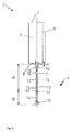
- the Fig. 3 shows in a schematic cross section an apparatus for producing refractory glasses or refractory glass-ceramics, in batch operation according to the present invention.
- the device 1 comprises the crucible 2 according to the Fig. 2 which is received in a container formed of a lower container portion 19 and the upper container portion 20.
- the crucible 2 is received in the container so that the upper edge of the crucible 2 does not project beyond the upper edge of the upper container portion 20.
- the upper container portion 20 is covered by a cover 21.
- the thus formed container is sufficiently sealed to the ambient atmosphere, so that in the interior of the container where the crucible 2 is received, a protective gas atmosphere can be formed, so that undesirable oxide formation of the iridium or the high-iridium-containing material of the crucible 2 and the section A of the outlet pipe 4 (see Fig. 2 ) can be prevented.
- a water-cooled induction coil 3 Around the crucible 2 around a water-cooled induction coil 3 is arranged, which runs around the crucible 2 spirally and with non-vanishing slope around.
- the induction coil 3 is arranged at a small distance from the outer wall of the crucible 2, preferably at a distance of about 60 to 80 mm.
- a refractory cylinder 23 Between the induction coil 3 and the crucible 2 is a refractory cylinder 23, which surrounds the crucible 2 radially and is closed at the bottom by the second bottom member 26 and the first bottom member 25.
- the resulting gap between the inner circumferential surface of the refractory cylinder 23 and the outer peripheral surface of the crucible 2 is heaped up with MgO beads 24 to ensure sufficient dimensional stability of the crucible 2 even at temperatures above about 2000 ° C.
- the beads of the ball bed 24 must be sufficiently temperature and dimensionally stable and resistant to oxidation at the temperatures specified.
- MgO is used as the material of the ball bed, the present
- the invention is not limited thereto.
- a use of ZrO 2 is for example also feasible.
- the beads of the ball bed 24 may also have a deviating from the spherical shape surface shape. Overall, however, in the space between the inner peripheral surface of the cylinder 23 and the outer peripheral surface of the crucible 2, a sufficient gas flow, in particular inert gas flow, is maintained, so that the crucible 2 is flowed around by an inert inert gas to undesirable oxide formation of the iridium or the high-iridium Anlagenn Material of the crucible 2 to prevent.
- the inventors have found that sufficient gas flow in the aforesaid gap can be ensured when the beads of the ball fill 24 have a diameter of at least about 2.0 mm, more preferably at least about 2.5 mm and more preferably at least about 3, 0 mm.
- the induction coil 3 is operated by a converter with a connected load of about 50 kW at a frequency of about 10 kHz.
- a converter with a connected load of about 50 kW at a frequency of about 10 kHz can be operated by a converter with a connected load of about 50 kW at a frequency of about 10 kHz.
- an iridium sleeve 27 is provided on the outer peripheral surface of the cylindrical portion of the crucible 2, in which a suitable temperature sensor is arranged. Also possible is a temperature measurement with Ir-PtIr40 thermocouples or with a two-color pyrometer, the (not shown) via an optical fiber, consisting for example of a sapphire fiber (to ensure a temperature measurement above 2000 ° C) through the passage 28 of the upper Container portion 20 is inserted therethrough. However, it is also possible to measure the temperature using a two-color pyrometer without an optical fiber, depending on the focal length (measuring distance) and the size of the measuring surface. For temperature monitoring, there are also other thermocouples, not shown, for example of the type B, in the first bottom portion 25 and / or in the second bottom portion 26 and at other suitable locations in the container.
- the container is formed substantially in three parts and comprises the lower container portion 19, the upper container portion 20 and the cover 21. These container portions are suitably made of a suitable stainless steel.
- the upper container portion 20 is double-walled. The annular gap between the inner wall and the outer wall of the upper container portion 20 can be traversed by a coolant, preferably water.
- the upper tank portion 20 has an upper coolant port 35 and a lower coolant port 36.
- the side walls of the upper container portion 20 are cylindrical, adapted to the basic shape of the crucible 2 and the induction coil surrounding it 3.
- the distance between the inner wall of the upper tank portion 20 and the outer peripheral surface of the induction coil 3 is sufficiently selected to effectively prevent melting of the inner wall of the tank portion 20 upon application of the conventional heating powers to the induction coil 3.
- the distance between the inner wall of the upper tank portion 20 and the outer peripheral surface of the induction coil 3 is about 120 mm.
- the upper container portion 20 is flanged onto the lower container portion 19.
- the lower container portion 19 is generally bell-shaped and comprises two cylindrical sections, each having different outer diameters.
- the upper cylindrical portion of the lower tank portion 19 serves to receive the crucible 2 and floor members 25, 26 supporting it, while the lower cylindrical portion of the lower tank portion 19 serves to receive and pass the spout 4 to the ambient atmosphere.
- the annular gap of the lower container section 19 can also be traversed by a coolant, preferably water, for which purpose an upper coolant connection 37 and a lower coolant connection 38 are provided on the lower container section 19.
- the cover 21 On the upper peripheral edge of the upper container portion 20, the cover 21 is placed, preferably flanged, which consists of stainless steel.
- the cover 21 can be lifted by loosening bolts, not shown, or can be pivotally mounted or laterally displaceable to ensure replacement of the recorded in the container crucible 2.
- a cover brick 29 Above the crucible 2 is a cover brick 29 which is formed of a suitable refractory material, for example of MgO or mullite, preferably with a cladding of noble metal alloy (Pt / Rh30). Also, the cover brick 29 can be taken out of the opening of the cover 21 or pivoted out, for example, for maintenance and installation work on the recorded in the container crucible 2. As in the Fig.
- the crucible 2 is closed at its upper edge by a cover 31, which in turn has a jacket 18 which is cylindrically shaped and penetrates the top brick 29 to the ambient atmosphere.
- the design of this cover can be made either completely in Ir or Ir alloys or in Pt alloys, preferably Pt / Rh 20. A combination of the two alloys (Part 31 of Ir and Part 18 of oxidation-resistant noble metal, for example, Pt / Rh20) is possible.
- the cover brick 40 preferably made of ceramic material (MgO, mullite) or ceramic enclosed in precious metal, can be removed and placed back in the crucible 2 during the low-melting of the glass melt for introducing glass mixture or raw material.
- a passage 30 is provided in the lower container portion 19.
- a separate gas line (not shown) may also be provided through the media feedthrough 30
- Melting crucible 2 are passed through to purge an internal volume of the crucible 2 separately from the internal volume of the container with a protective gas atmosphere or to pressurize.
- the crucible 2 can be designed to be resistant to pressure to some extent, so that a certain overpressure in the crucible 2 can be constructed.
- a pressure transducer may be provided in the crucible 2, the cables are also guided over the media feedthrough 30 to the outside.
- the bottom of the crucible 2 sits on a first floor element 25 over the entire surface.
- the profile of the first floor element 25 is adapted to the shape of the bottom of the crucible 2, designed to be tapered in the illustrated embodiment.
- the first bottom element 25 serves for the mechanical support of the crucible 2 and a sufficient heat insulation.
- the first bottom member 25 is formed of MgO.
- the crucible 2 supporting the first bottom member 25, the refractory cylinder 23 and the induction coil 3 are supported on a second bottom member 26 which is supported on the bottom of the lower container portion 19.
- the second bottom element 26 serves for a mechanical support of this arrangement and a sufficient thermal insulation.
- the thickness of the second floor member 26 is sufficiently selected.
- the material of the second bottom element 26 must be sufficiently temperature and dimensionally stable and resistant to oxidation.
- the second bottom member 26 is formed of ZrSiO 4 .
- the first bottom member 25 and the second bottom member 26 have an opening through which the spout 4 is made to the ambient atmosphere.
- the lower cylindrical portion of the lower tank portion 19 surrounds the spout 4.
- the spout 4 is located in the lower tank portion except for a small portion (segmented by the reference numeral 15) of the lower tube portion of oxidation-resistant noble metal and becomes the tank portion with a shutter member not shown 19 closed gas-tight to prevent ingress of air atmosphere.
- the transition region 39 between the section A and the section B of the outlet pipe 4 (see Fig. 2 ) as far as possible below the two bottom elements 25, 26.
- the segments of the section A of the irrigation outflow tube 4 or the high iridium containing material may be cooled down so that the risk of oxide formation of the iridium or the high iridium containing alloy can be prevented.
- the location of the transition region 39 in the Fig. 3 It is therefore intended to be illustrative only and not to be to scale.
- a gas inlet 22 which serves to supply a protective gas in the inner volume of the container.
- the gas inlet 22 is connected to a gas line, not shown, and a gas reservoir, not shown.
- the shielding gas maintains neutral to slightly oxidizing conditions in the interior volume of the container.
- a protective gas can be used with an oxygen content between about 5x 10- 3% and about 5%, and more preferably between about 0.5% and about 2%.
- the inert gas used is inert and reacts with the iridium or the high-iridium-containing alloy to a negligible extent.
- argon or nitrogen are suitable as inert, inert protective gas.
- the aforementioned minor oxygen additives can prevent reactions between the material of the crucible and glass components (reduction of glass components with subsequent alloying).
- the interior of the crucible is purged with inert gas to protect the crucible inner wall against oxidation by atmospheric oxygen.
- the purging with the protective gas can be limited to the iridium ambiencen sections of the crucible 2, since it was surprisingly found that an oxygen impingement with subsequent destructive oxidation of the crucible 2 occurs only in the uppermost centimeters of the arrangement, which in the arrangement according to the Fig. 3 preferably consists of a PtRh20 cover 31. But it can also be used a lid made of iridium or an iridium alloy, if small precious metal losses are taken by oxidation of iridium in purchasing. For this purpose, a certain minimum distance between the cover 31 and the region of the crucible 2, which is surrounded by the induction coil 3 may be provided.
- the container need not be designed pressure-tight, since it is sufficient if a steady state in the internal volume of the container is formed, which ensures a sufficient protective gas atmosphere therein.
- the container 5 can also be pressure-tight in order to suppress the penetration of oxygen from the ambient atmosphere into the interior volume of the container even more effectively.
- melting temperatures of about 2000 ° C or beyond can be achieved.
- all physical and chemical processes of the melting process are significantly accelerated.
- the process times are included simultaneous increase in quality significantly reduced.
- glasses or glass ceramics with new, surprisingly advantageous properties can be achieved.
- the device according to the invention is operated in two different operating states.
- the temperature of the crucible 2 depending on the glass batch or raw material, can also be chosen to be comparatively low, but the temperature of the crucible 2 is preferably maintained above about 2000 ° C. during the low-melting process.
- the temperature of the crucible 2 is maintained by means of the induction coil 3 at a temperature far above a later processing temperature of the molten glass. Due to the very high temperatures that are possible according to the invention, the refining processes can be much more effective.
- the temperature of the outlet pipe 4 is kept comparatively low and below the melting temperature of the molten glass. In the outlet pipe 4 thus forms a plug of viscous or solidified glass melt, which prevents leakage of the molten glass from the crucible 2.
- conventional refining agents are activated in the molten glass.
- a stirring device for stirring the molten glass in the crucible 2, a stirring device, not shown, may be arranged in the crucible 2 or inserted through the cover 31 in this.
- the stirring device consists of the abovementioned iridium or of the abovementioned high-iridium-containing alloy.
- the stirring device itself can also be used for blowing in, for example reducing, gases.
- the transition region between liquid glass melt and highly viscous or solidified plug is fluid, but is preferably located within the outlet pipe 4. Within the crucible 2 thus a very homogeneous molten glass is formed.
- the outlet pipe 4 does not necessarily need to be heated, because by appropriate design of the lower cylindrical portion of the lower tank portion 19 for sufficient cooling of the outlet pipe 4 can be provided by heat radiation. In principle, however, the outlet pipe 4 can also be controlled or regulated heated or cooled during the first operating state.
- the temperature of the molten glass in the crucible 2 for taking a second operating state is lowered to a processing temperature and the spout 4 is heated to the processing temperature.
- the processing temperature is chosen so that the glass melt has a desired viscosity, or is suitable for the formation of moldings.
- the processing temperature is above the melting point of the molten glass and can be changed by changing the heating power of the induction coil 3 and the heating power of the heating flow to the outlet pipe 4.
- the crucible 2 and the outlet pipe 4 can also be kept at different temperatures, for example with a temperature difference of about 10 to 40 ° C.
- the plug melts or softens in the outlet pipe 4, so that the molten glass flows out of the outlet pipe 4.
- the glass melt through the profile of the outlet pipe 4 and / or by other hot forming devices, such as a die, such as these in the Fig. 3 is indicated by the reference numeral 15, shaped.
- both solid bodies, for example rods, as well as hollow bodies, for example tubes, can be formed.
- the exiting glass melt can also be quenched and thus further processed into powder.
- the device according to the invention basically all known types of glass can be produced.
- the device according to the invention is particularly preferred for glasses or glass ceramics which have only a very small proportion of network converters, in particular alkali oxides, or for glasses or glass ceramics which contain a high proportion of high-melting oxides, for example SiO 2 , Al 2 O 3 , ZrO 2 , Nd 2 O, or Ta 2 O 5 .
- the glass or the glass-ceramic has a content of SiO 2 of about 80% by weight to about 90% by weight, a content of Al 2 O 3 of about 0% by weight to about 10% by weight, a proportion from B 2 O 3 from about 0% to about 15% by weight and less than about 3% by weight R 2 O, wherein the amount of Al 2 O 3 and B 2 O 3 together is about 7% to about Is 20% by weight and R is an alkali element of a group consisting of Li, Na, K, Rb and Cs. Glasses of the aforementioned composition could not be produced with crucibles of the prior art or not in sufficient quality.
- the glass composition may additionally comprise further high melting oxides up to about 20% by weight of MgO and / or up to about 10% by weight, more preferably up to about 5% by weight, for example TiO 2 , ZrO 2 , Nb 2 O 5 , Ta 2 O 5 , WO 3 or MoO 3 or mixtures thereof.
- a preferred use according to the invention relates to the production of so-called transition glasses, which are used to produce a fusion bond between a glass with a low coefficient of thermal expansion and a glass with a high thermal expansion coefficients serve, for example, between quartz glass with a coefficient of thermal expansion of 0.5x10 -6 K -1 and between Duranglas with a thermal expansion coefficient of about 3.3x10 -6 K -1 .
- transition glasses can be produced with coefficients of thermal expansion specially matched to the two types of glass to be connected, as described below.
- Table 1 summarizes the composition and the determined coefficients of thermal expansion of various transition glasses made in accordance with the present invention and the subsequent embodiment.
- Table 1 Oxides in (% by weight) 8228 8229 8230 New 1 New 2 SiO 2 82.1 87.0 83.6 83.0 82.5 B 2 O 3 12.3 11.6 11.0 12.5 8.6 Al 2 O 3 5.3 - 2.5 4.5 5.5 Na 2 O - 1.4 2.2 - - K 2 O - - 0.3 Läuterm.
- the transition glass types 8228, 8229 and 8230 have a coefficient of thermal expansion of 1.3x10 -6 K -1 , 2.0x10 -6 K -1 and 2.7x10 -6 K -1, respectively, making them ideal for manufacturing a fusion between quartz glass and Duranglas. All of the glass types identified in Table 1 above have a refractive index of less than about 1.47.
- the glass grades of columns 4 and 5 of Table 1 can not be made with conventional non-iridium-containing crucibles according to the prior art.
- Fig. 4 representing the spectral transmission of glass grade 8228 according to Table 1.
- the spectral transmission of a glass grade 8228 made with a device according to the invention and Embodiment 1 set forth below is compared to the spectral transmission of a glass of identical composition incorporated with a conventional prior art non-iridium crucible Temperatures of 1760 ° C has been produced.
- the upper curve denotes the spectral transmission of a glass type 8228 produced according to the invention in accordance with the exemplary embodiment 1 set forth below and the lower curve shows the spectral transmission of a glass grade 8228 according to the prior art.
- the spectral transmission is higher in the near UV range and starts earlier by about 30 nm.
- the spectral transmission of glass types according to the invention in the visible spectral range between about 400 nm and about 800 nm is significantly greater than the spectral transmission of the corresponding type of glass according to the prior art.
- the glass according to the invention is characterized in that the transmission in the aforementioned visible wavelength range, based on a substrate thickness of about 20 mm, at least about 65%, more preferably at least about 75% and more preferably at least about 80%.
- Such high transmissions could not be observed for prior art glass types of appropriate composition, nor can they be achieved in the prior art because of the significantly lower processing temperatures resulting from the use of non-iridium containing crucible material.
- the water absorption bands at about 1350 nm and about 2200 nm in the glass according to the invention are significantly smaller than the corresponding water absorption bands in a corresponding glass according to the prior art.
- the smaller water absorption bands are due to the significantly higher processing temperatures compared to the prior art, which lead to a further expulsion of water and to an even more effective reduction of hydrogen-containing compounds in the molten glass during the refining process.
- the glass type 8228 according to the invention but also other types of glass with inventive glass composition, characterized in that, based on a substrate thickness of about 20 mm, the transmission in the range of water absorption band at about 1350 nm is at least about 75% and / or the transmission, based on a substrate thickness of about 20 mm, in the region of the water absorption band at about 2200 nm is at least about 50%, more preferably at least about 55%.
- Table 2 summarizes the drums of raw materials used for 26.25 kg of the glass of composition 8228 according to Table 1, Example 1 (8228): Table 2 oxide Dimensions-% raw material Weighing [g] SiO 2 82.1 silica flour 18570 B 2 O 3 12.3 boric acid 4952 Al 2 O 3 5.3 aluminum hydroxide 1845 SnO 2 0.2 Tin (IV) oxide 45
- the properties of the molten glass are also listed in Tab. 1, Example 1 (8228). Due to the easier handling, the batch is divided into three batches and individually weighed or mixed. After mixing the mixture, the mixture is moistened with deionised water (3 x 800 ml) and mixed again. This is done to reduce the dustiness of the batch when loading. After moistening resulting larger Gemengebrocken be removed by subsequent screening and crushed. This reduces the formation of aggregate inclusions and gypsum in the glass.
- the average temperature during insertion is about 1990 ° C at the crucible and about 1760 ° C at the glass surface.
- the setting of the temperature is made manually via the voltage of the medium frequency heating.
- the set voltage is between 65% and 67%, corresponding to 355V - 370V. This results in a power of about 55% ( ⁇ 28kW) of a standard frequency converter (50 kW maximum power).
- the amount of food is about 4-6 porcelain spoons (each about 70g mixture) every 15 minutes. An entry of atmospheric oxygen over the loose mixture can not be avoided in this method, but is also advantageous because it prevents a reduction of the glass components.
- the high melting temperatures also make it possible to use non-toxic high-temperature initiators, such as SnO 2 instead of As 2 O 3 .
- the quantity addition of the refining agent adapted to the PtRh30 crucible can be correspondingly reduced. Glass compositions that are not meltable or only at great expense due to their high viscosity can be produced economically in the iridium crucible.
- iridium has the advantage over the PtRh30 alloy of causing less color cast (Rh) in the glass.
- Rh color cast
- Cordierite-type glass ceramics whose composition for SiO 2 is in the range between 40% and 60% by weight for Al 2 O 3 in the range between 25% and 45% by weight and for MgO in the range of 10% to 20% by weight
- the glass composition may additionally comprise further high melting oxides up to about 10% by weight, more preferably up to about 5% by weight, for example TiO 2 , ZrO 2 , Nb 2 O 5 , Ta 2 O 5 or WO 3 or mixtures thereof.
- MoO 3 is also possible, but its use could lead to a coloration of the glass, depending on the application.
- various shaped bodies such as rods, fibers, tubes, ribbons (glass strips) and ingots or castings can be produced.
- the crucible temperature is lowered and the pipe heating is switched on.
- the temperature at the end of the outlet pipe is adjusted to the processing temperature (corresponds to a viscosity of 10 4 dpa ⁇ s).
- the diameter of the molding is set via the parameters temperature and drawing speed.
- For pipes and rods is to adjust the outer diameter at the end of the pipe a separately heated (directly or indirectly via a muffle) nozzle arranged.
- the wall thickness is set via a double nozzle.
- the glass level in the crucible drops during shaping, which corresponds to a decrease in the static pressure.
- the drawing speed usually by means of a drawing machine consisting of two driven rollers
- temperature or the pressure above the molten glass the drop of the glass level is compensated.
- the dimensions of the fittings are each dependent on the tube inner diameter. For example, rods with a diameter of 30 mm are manufactured from 20 mm to 400 ⁇ m (fibers). In combination with a double nozzle for the production of tubes, dimensions of 18 mm up to capillaries are possible.
- thermal stresses occur during the shaping at the condition of ⁇ > 5, which, however, are compensated by a targeted thermal aftertreatment.
- iridium as tube material and the resulting low wettability (adhesion of the glass to the tube wall) make tighter manufacturing tolerances possible.
- the glass from the outlet pipe runs on water-cooled rotating rolls.
- the pipe diameter is adjusted depending on the glass viscosity.
- glass stiffeners are produced without defined dimensions.
- the properties of the molten glass are also listed in the table above for the exemplary embodiment cordierite. Due to the easier handling, the batch is divided into three batches and individually weighed or mixed. After mixing the mixture, the mixture is moistened with deionised water (3 x 800 ml) and mixed again. This is done to reduce the dustiness of the batch when loading. After moistening resulting larger Gemengebrocken be removed by subsequent screening and crushed. This reduces the formation of Gemengeein Whyn and Gispen in the glass. The average temperature when inserting is about 1850 ° C at the crucible. The temperature is set via a controller as specified.
- the loading amount is about 6-8 porcelain spoons (each about 70g mixture) every 15 minutes. An entry of atmospheric oxygen over the loose mixture can not be avoided in this method, but is also advantageous because it prevents a reduction of the glass components.
- the refining time can be kept very short with 3-6 h and / or a low viscosity can be specified.
- the temperature in the crucible and in the tube is approx. 1650 ° C.
- the throughput is approx. 200g / min to 300g / min. This results in an increase in throughput over conventional methods by 100% or 200%.
- glass ceramics of any desired composition can be produced by the aforementioned method. Preference is given to producing glass ceramics whose composition is disclosed in the following patents or patent applications, the disclosure content of which is expressly incorporated herein by reference in this patent application: EP 0 220 333 B1 corresponding US 5,212,122 . DE 196 41 121 A1 . DE 43 21 373 C2 corresponding US 5,446,008 . DE 196 22 522 C1 corresponding US 5,922,271 . DE 199 07 038 A1 corresponding US 09 / 507,315 . DE 199 39 787 A1 corresponding WO 02/16279 . DE 100 17 701 C2 corresponding US 09 / 829,409 . DE 100 17 699 A1 corresponding US 09 / 828,287 and EP 1 170 264 A1 corresponding US 6,515,263 ,
Landscapes
- Chemical & Material Sciences (AREA)
- Engineering & Computer Science (AREA)
- Materials Engineering (AREA)
- Organic Chemistry (AREA)
- Life Sciences & Earth Sciences (AREA)
- Chemical Kinetics & Catalysis (AREA)
- General Chemical & Material Sciences (AREA)
- Geochemistry & Mineralogy (AREA)
- Glass Compositions (AREA)
- Glass Melting And Manufacturing (AREA)
- Crucibles And Fluidized-Bed Furnaces (AREA)
Applications Claiming Priority (2)
| Application Number | Priority Date | Filing Date | Title |
|---|---|---|---|
| DE10348466A DE10348466B4 (de) | 2003-10-14 | 2003-10-14 | Vorrichtung und Verfahren zur Herstellung von hoch schmelzenden Gläsern oder Glaskeramiken und Verwendung einer Vorrichtung |
| DE10348466 | 2003-10-14 |
Publications (2)
| Publication Number | Publication Date |
|---|---|
| EP1524243A1 EP1524243A1 (de) | 2005-04-20 |
| EP1524243B1 true EP1524243B1 (de) | 2012-09-19 |
Family
ID=34353463
Family Applications (1)
| Application Number | Title | Priority Date | Filing Date |
|---|---|---|---|
| EP04105029A Expired - Lifetime EP1524243B1 (de) | 2003-10-14 | 2004-10-13 | Vorrichtung und Verfahren zur Herstellung von hoch schmelzenden Gläsern oder Glaskeramiken sowie Glas oder Glaskeramik |
Country Status (4)
| Country | Link |
|---|---|
| US (1) | US20050109062A1 (enExample) |
| EP (1) | EP1524243B1 (enExample) |
| JP (1) | JP4707989B2 (enExample) |
| DE (2) | DE10348466B4 (enExample) |
Families Citing this family (23)
| Publication number | Priority date | Publication date | Assignee | Title |
|---|---|---|---|---|
| JP4456071B2 (ja) * | 2003-04-23 | 2010-04-28 | ステラケミファ株式会社 | フッ化物結晶の製造装置 |
| DE102004011218B4 (de) | 2004-03-04 | 2006-01-19 | Schott Ag | Röntgenopakes Glas, Verfahren zu seiner Herstellung und seine Verwendung |
| JP4276627B2 (ja) * | 2005-01-12 | 2009-06-10 | ソルボサーマル結晶成長技術研究組合 | 単結晶育成用圧力容器およびその製造方法 |
| US20060242996A1 (en) * | 2005-04-27 | 2006-11-02 | Gilbert Deangelis | System and method for controlling the environment around one or more vessels in a glass manufacturing system |
| DE102005047006A1 (de) | 2005-09-30 | 2007-04-05 | Schott Ag | Verbundsystem, Verfahren zur Herstellung eines Verbundsystems und Leuchtkörper |
| DE102006003531A1 (de) * | 2006-01-24 | 2007-08-02 | Schott Ag | Verfahren und Vorrichtung zum blasenfreien Transportieren, Homogenisieren und Konditionieren von geschmolzenem Glas |
| DE102006003521B4 (de) * | 2006-01-24 | 2012-11-29 | Schott Ag | Vorrichtung und Verfahren zum kontinuierlichen Läutern von Gläsern mit hohen Reinheitsanforderungen |
| DE102006051049B4 (de) * | 2006-10-30 | 2013-05-29 | Schott Ag | Oxidationsgeschützte Behältnisse aus Iridium zum Transportieren und/oder Konditionieren einer Glasschmelze, insbesondere für den kontinuierlichen Betrieb, sowie Verfahren |
| JP2008143718A (ja) * | 2006-12-05 | 2008-06-26 | Canon Inc | 光学ガラス |
| DE102007023497B4 (de) * | 2007-05-18 | 2010-08-05 | Schott Ag | Verfahren und Vorrichtung zur Herstellung von Gläsern, Glaskeramiken oder Keramiken sowie deren Verwendung |
| JP5347424B2 (ja) * | 2008-10-20 | 2013-11-20 | 旭硝子株式会社 | ガラス製造装置および製造方法 |
| US8650910B2 (en) * | 2010-08-23 | 2014-02-18 | Corning Incorporated | Apparatus for homogenizing a glass melt |
| JP6048404B2 (ja) * | 2011-07-15 | 2016-12-21 | 日東紡績株式会社 | ガラス溶融装置、ガラス繊維製造装置及びガラス繊維製造方法 |
| RU2555732C1 (ru) * | 2014-04-15 | 2015-07-10 | Открытое Акционерное Общество "Научно-Исследовательский Институт Технического Стекла" | Способ варки стекла |
| KR20180004205A (ko) | 2015-05-06 | 2018-01-10 | 코닝 인코포레이티드 | 용융된 재료를 가공하는 장치 및 방법 |
| JP2017075905A (ja) | 2015-10-16 | 2017-04-20 | 日本特殊陶業株式会社 | 温度センサ |
| JP6545627B2 (ja) | 2016-02-19 | 2019-07-17 | 日本特殊陶業株式会社 | 温度センサ |
| KR102415723B1 (ko) * | 2017-11-20 | 2022-07-04 | 코닝 인코포레이티드 | 용탕 교반 시스템 및 용탕 교반 방법 |
| CN115884944A (zh) * | 2020-03-30 | 2023-03-31 | 康宁公司 | 用于减少玻璃熔体系统中的缺陷的设备与方法 |
| EP4005989A1 (en) | 2021-03-25 | 2022-06-01 | Schott Ag | Glass article and method of making the same |
| CN113045181A (zh) * | 2021-03-31 | 2021-06-29 | 彩虹集团(邵阳)特种玻璃有限公司 | 一种盖板及基板玻璃制造中铂金通道的冲洗方法 |
| CN113998868B (zh) * | 2021-12-07 | 2023-07-25 | 山东高速工程检测有限公司 | 制备钛钡体系高折射率玻璃的装置及方法 |
| EP4328197A1 (en) * | 2022-08-23 | 2024-02-28 | Schott Ag | Glass rod, set of glass rods, and process for the production of a glass rod |
Family Cites Families (28)
| Publication number | Priority date | Publication date | Assignee | Title |
|---|---|---|---|---|
| FR533136A (fr) * | 1915-06-24 | 1922-02-22 | Corning Glass Works | Composition pour la fabrication de tous objets pouvant être chauffés au four |
| US1676331A (en) | 1925-03-15 | 1928-07-10 | E T Brown | Heat resistant borosilicate glass |
| BE491015A (enExample) * | 1951-10-25 | |||
| US3066504A (en) * | 1960-03-22 | 1962-12-04 | Babcock & Wilcox Co | Apparatus for forming a ceramic filament |
| US3233993A (en) * | 1962-03-06 | 1966-02-08 | Bausch & Lomb | Apparatus for processing a vitreous composition |
| GB1222248A (en) * | 1968-03-11 | 1971-02-10 | Pilkington Brothers Ltd | Improvements in or relating to containers for molten glass |
| CH624151A5 (enExample) * | 1976-08-05 | 1981-07-15 | Alusuisse | |
| SU695979A1 (ru) * | 1978-01-06 | 1979-11-05 | Предприятие П/Я В-2268 | Стекло |
| US4504302A (en) * | 1982-05-24 | 1985-03-12 | Carman Justice N | Homogenizing apparatus glass making furnace and method of homogenizing glass |
| JPS6183632A (ja) * | 1984-09-27 | 1986-04-28 | Kiyoshi Hajikano | ガラス溶解用ホツパ− |
| ATE51214T1 (de) * | 1985-10-26 | 1990-04-15 | Schott Glaswerke | Durchsichtige farbige glaskeramik mit guter temperaturbelastbarkeit und variabel einstellbarer transmission im ir-bereich. |
| JPS638225A (ja) * | 1986-02-07 | 1988-01-14 | Tokai Denki Kk | ガラス質溶解炉 |
| JPH01219028A (ja) * | 1988-02-29 | 1989-09-01 | Hoya Corp | ガラスの溶融方法 |
| JPH0222132A (ja) * | 1988-07-07 | 1990-01-25 | Furuya Kinzoku:Kk | 高品位ガラスの溶解装置 |
| JPH0264244A (ja) | 1988-08-30 | 1990-03-05 | Toyota Motor Corp | 内燃機関の燃料噴射量制御装置 |
| DE4321373C2 (de) * | 1993-06-26 | 1995-12-14 | Schott Glaswerke | Glaskeramik mit hoher Transmission im Wellenlängenbereich von 2700 bis 3300 nm, Verfahren zu deren Herstellung und deren Verwendung |
| DE4338128C1 (de) * | 1993-11-08 | 1995-05-18 | Jenaer Glaswerk Gmbh | Borosilikatglas mit hoher Transmission im UV-Bereich, niedriger Wärmeausdehnung und hoher chemischer Beständigkeit, Verfahren zu seiner Herstellung und seine Verwendung |
| DE19622522C1 (de) | 1996-06-05 | 1998-01-22 | Schott Glaswerke | Verfahren zur Herstellung von dichtgesinterten Glaskeramik-Formkörpern |
| DE19907038C2 (de) * | 1999-02-19 | 2003-04-10 | Schott Glas | Transluzente oder opake Glaskeramik mit Hochquarz-Mischkristallen als vorherrschender Kristallphase und deren Verwendung |
| DE19939781C2 (de) * | 1999-08-21 | 2003-06-18 | Schott Glas | Skulltiegel für das Erschmelzen oder das Läutern von anorganischen Substanzen, insbesondere von Gläsern und Glaskeramiken |
| DE19939787C2 (de) * | 1999-08-21 | 2003-11-27 | Schott Glas | Transparente, mit Vanadiumoxid-Zusatz dunkel einfärbbare Glaskeramik mit Hochquarz-Mischkristallen als vorherrschende Kristallphase, Verfahren zu ihrer Herstellung und ihre Verwendung |
| US6482758B1 (en) * | 1999-10-14 | 2002-11-19 | Containerless Research, Inc. | Single phase rare earth oxide-aluminum oxide glasses |
| DE10017699B9 (de) * | 2000-04-08 | 2008-04-17 | Schott Ag | Verwendung eines transparenten Scheibenpaketes als Verglasung für Sichtfenster in Raumstationen, Flugkörpern sowie Polarstationen in arktischen und antarktischen Breiten |
| DE10017701C2 (de) * | 2000-04-08 | 2002-03-07 | Schott Glas | Gefloatetes Flachglas |
| US6632086B1 (en) * | 2000-05-22 | 2003-10-14 | Stanley M. Antczak | Quartz fusion crucible |
| EP1170264B1 (de) * | 2000-07-04 | 2003-09-03 | Schott Glas | Transluzente Glaskeramik, Verfahren zur Herstellung einer transluzenten Glaskeramik sowie deren Verwendung |
| JP4939723B2 (ja) | 2000-08-24 | 2012-05-30 | ショット アクチエンゲゼルシャフト | 酸化バナジウムを使用することにより暗色化された透明ガラスセラミック |
| US20050022560A1 (en) * | 2003-07-03 | 2005-02-03 | Engelhard Corporation | Tank for melting solder glass |
-
2003
- 2003-10-14 DE DE10348466A patent/DE10348466B4/de not_active Expired - Fee Related
- 2003-10-14 DE DE10362074A patent/DE10362074B4/de not_active Expired - Fee Related
-
2004
- 2004-10-13 EP EP04105029A patent/EP1524243B1/de not_active Expired - Lifetime
- 2004-10-13 JP JP2004298326A patent/JP4707989B2/ja not_active Expired - Fee Related
- 2004-10-14 US US10/963,759 patent/US20050109062A1/en not_active Abandoned
Also Published As
| Publication number | Publication date |
|---|---|
| DE10362074B4 (de) | 2007-12-06 |
| US20050109062A1 (en) | 2005-05-26 |
| JP2005119959A (ja) | 2005-05-12 |
| EP1524243A1 (de) | 2005-04-20 |
| DE10348466A1 (de) | 2005-05-19 |
| DE10362074A1 (de) | 2005-09-22 |
| DE10348466B4 (de) | 2007-05-31 |
| JP4707989B2 (ja) | 2011-06-22 |
Similar Documents
| Publication | Publication Date | Title |
|---|---|---|
| EP1524243B1 (de) | Vorrichtung und Verfahren zur Herstellung von hoch schmelzenden Gläsern oder Glaskeramiken sowie Glas oder Glaskeramik | |
| DE102007023497B4 (de) | Verfahren und Vorrichtung zur Herstellung von Gläsern, Glaskeramiken oder Keramiken sowie deren Verwendung | |
| DE102007008299B4 (de) | Verfahren zur Herstellung von Gläsern, wobei die chemische Reduktion von Bestandteilen vermieden wird | |
| EP1981819B1 (de) | Vorrichtung und verfahren zum kontinuierlichen läutern von gläsern mit hohen reinheitsanforderungen | |
| EP2184264B1 (de) | Vorrichtung zum blasenfreien Transportieren, Homogenisieren und Konditionieren von geschmolzenem Glas | |
| DE60129376T3 (de) | Verfahren und Vorrichtung zur Herstellung von Quarzglaskörpern | |
| DE2904317C2 (de) | Verfahren zum Herstellen von geschmolzenem Glas | |
| EP1618074B1 (de) | Schmelzen und läutern in wannen mit gekühlten wänden | |
| DE3906270C2 (de) | Verfahren und Vorrichtung zum Schmelzen von Glas | |
| WO2004052054A1 (de) | Verfahren und vorrichtung zur beheizung von schmelzen | |
| EP0564707A1 (de) | Verfahren und Vorrichtung zur Herstellung eines Verbundkörpers aus Glas | |
| EP1434741A2 (de) | Vorrichtung und verfahren zum kontaminationsarmen schmelzen von glas oder glaskeramik | |
| WO2004052797A1 (de) | Verfahren zur herstellung von borosilicatgläsern, boratgläsern und kristallisierenden borhaltigen werkstoffen | |
| DE2729188A1 (de) | Hochtemperatur-reaktor und verfahren zu seinem betrieb | |
| DE102010037437B4 (de) | Glasschmelzanlage sowie Verfahren zum Betreiben einer solchen Glasschmelzanlage | |
| DE10133469B4 (de) | Vorrichtung zum Schmelzen hochreiner optischer Gläser | |
| DE20321430U1 (de) | Vorrichtung zur Herstellung von hoch schmelzenden Gläsern oder Glaskeramiken sowie Glas oder Glaskeramik | |
| DE102006051049B4 (de) | Oxidationsgeschützte Behältnisse aus Iridium zum Transportieren und/oder Konditionieren einer Glasschmelze, insbesondere für den kontinuierlichen Betrieb, sowie Verfahren | |
| DE102011105145B4 (de) | Vorrichtung zum Transportieren, Homogenisieren und/oder Konditionieren einer anorganischen nichtmetallischen Schmelze, Verfahren zur Herstellung eines Glases und/oder einer Glaskeramik sowie Verfahren zur Herstellung einer Sicke in Iridiumblech | |
| DE10202024B4 (de) | Vorrichtung und Verfahren zum kontaminationsarmen Schmelzen einer Substanz | |
| DE102006019647B4 (de) | Verfahren zum Dimensionieren einer drehbaren Vorrichtung zum Herstellen einer Schmelze sowie drehbare Vorrichtung | |
| DE102006039225B4 (de) | Verfahren und Vorrichtung zum Hochtemperatureinschmelzen und -läutern von Materialien | |
| DE102004043458B4 (de) | Vorrichtung und Verfahren zum Transport und zur Konditionierung von Schmelzen |
Legal Events
| Date | Code | Title | Description |
|---|---|---|---|
| PUAI | Public reference made under article 153(3) epc to a published international application that has entered the european phase |
Free format text: ORIGINAL CODE: 0009012 |
|
| 17P | Request for examination filed |
Effective date: 20041013 |
|
| AK | Designated contracting states |
Kind code of ref document: A1 Designated state(s): AT BE BG CH CY CZ DE DK EE ES FI FR GB GR HU IE IT LI LU MC NL PL PT RO SE SI SK TR |
|
| AX | Request for extension of the european patent |
Extension state: AL HR LT LV MK |
|
| AKX | Designation fees paid |
Designated state(s): AT BE BG CH CY CZ DE DK EE ES FI FR GB GR HU IE IT LI LU MC NL PL PT RO SE SI SK TR |
|
| REG | Reference to a national code |
Ref country code: DE Ref legal event code: R079 Ref document number: 502004013756 Country of ref document: DE Free format text: PREVIOUS MAIN CLASS: C03B0005020000 Ipc: C03B0005160000 |
|
| RIC1 | Information provided on ipc code assigned before grant |
Ipc: C03B 5/425 20060101ALI20120328BHEP Ipc: C03B 5/187 20060101ALI20120328BHEP Ipc: C03B 5/26 20060101ALI20120328BHEP Ipc: C03B 5/167 20060101ALI20120328BHEP Ipc: C03B 5/06 20060101ALI20120328BHEP Ipc: C03B 5/02 20060101ALI20120328BHEP Ipc: C03C 3/091 20060101ALI20120328BHEP Ipc: C03B 17/04 20060101ALI20120328BHEP Ipc: C03C 3/085 20060101ALI20120328BHEP Ipc: C03B 5/16 20060101AFI20120328BHEP |
|
| GRAP | Despatch of communication of intention to grant a patent |
Free format text: ORIGINAL CODE: EPIDOSNIGR1 |
|
| GRAS | Grant fee paid |
Free format text: ORIGINAL CODE: EPIDOSNIGR3 |
|
| GRAA | (expected) grant |
Free format text: ORIGINAL CODE: 0009210 |
|
| AK | Designated contracting states |
Kind code of ref document: B1 Designated state(s): AT BE BG CH CY CZ DE DK EE ES FI FR GB GR HU IE IT LI LU MC NL PL PT RO SE SI SK TR |
|
| REG | Reference to a national code |
Ref country code: GB Ref legal event code: FG4D Free format text: NOT ENGLISH |
|
| REG | Reference to a national code |
Ref country code: CH Ref legal event code: EP |
|
| REG | Reference to a national code |
Ref country code: IE Ref legal event code: FG4D Free format text: LANGUAGE OF EP DOCUMENT: GERMAN |
|
| REG | Reference to a national code |
Ref country code: AT Ref legal event code: REF Ref document number: 575921 Country of ref document: AT Kind code of ref document: T Effective date: 20121015 |
|
| REG | Reference to a national code |
Ref country code: CH Ref legal event code: NV Representative=s name: E. BLUM & CO. AG PATENT- UND MARKENANWAELTE VSP |
|
| REG | Reference to a national code |
Ref country code: DE Ref legal event code: R096 Ref document number: 502004013756 Country of ref document: DE Effective date: 20121115 |
|
| PG25 | Lapsed in a contracting state [announced via postgrant information from national office to epo] |
Ref country code: CY Free format text: LAPSE BECAUSE OF FAILURE TO SUBMIT A TRANSLATION OF THE DESCRIPTION OR TO PAY THE FEE WITHIN THE PRESCRIBED TIME-LIMIT Effective date: 20120919 Ref country code: FI Free format text: LAPSE BECAUSE OF FAILURE TO SUBMIT A TRANSLATION OF THE DESCRIPTION OR TO PAY THE FEE WITHIN THE PRESCRIBED TIME-LIMIT Effective date: 20120919 |
|
| REG | Reference to a national code |
Ref country code: NL Ref legal event code: VDEP Effective date: 20120919 |
|
| PG25 | Lapsed in a contracting state [announced via postgrant information from national office to epo] |
Ref country code: SI Free format text: LAPSE BECAUSE OF FAILURE TO SUBMIT A TRANSLATION OF THE DESCRIPTION OR TO PAY THE FEE WITHIN THE PRESCRIBED TIME-LIMIT Effective date: 20120919 Ref country code: GR Free format text: LAPSE BECAUSE OF FAILURE TO SUBMIT A TRANSLATION OF THE DESCRIPTION OR TO PAY THE FEE WITHIN THE PRESCRIBED TIME-LIMIT Effective date: 20121220 Ref country code: SE Free format text: LAPSE BECAUSE OF FAILURE TO SUBMIT A TRANSLATION OF THE DESCRIPTION OR TO PAY THE FEE WITHIN THE PRESCRIBED TIME-LIMIT Effective date: 20120919 |
|
| BERE | Be: lapsed |
Owner name: SCHOTT A.G. Effective date: 20121031 |
|
| PG25 | Lapsed in a contracting state [announced via postgrant information from national office to epo] |
Ref country code: RO Free format text: LAPSE BECAUSE OF FAILURE TO SUBMIT A TRANSLATION OF THE DESCRIPTION OR TO PAY THE FEE WITHIN THE PRESCRIBED TIME-LIMIT Effective date: 20120919 Ref country code: EE Free format text: LAPSE BECAUSE OF FAILURE TO SUBMIT A TRANSLATION OF THE DESCRIPTION OR TO PAY THE FEE WITHIN THE PRESCRIBED TIME-LIMIT Effective date: 20120919 Ref country code: NL Free format text: LAPSE BECAUSE OF FAILURE TO SUBMIT A TRANSLATION OF THE DESCRIPTION OR TO PAY THE FEE WITHIN THE PRESCRIBED TIME-LIMIT Effective date: 20120919 Ref country code: ES Free format text: LAPSE BECAUSE OF FAILURE TO SUBMIT A TRANSLATION OF THE DESCRIPTION OR TO PAY THE FEE WITHIN THE PRESCRIBED TIME-LIMIT Effective date: 20121230 Ref country code: CZ Free format text: LAPSE BECAUSE OF FAILURE TO SUBMIT A TRANSLATION OF THE DESCRIPTION OR TO PAY THE FEE WITHIN THE PRESCRIBED TIME-LIMIT Effective date: 20120919 |
|
| PG25 | Lapsed in a contracting state [announced via postgrant information from national office to epo] |
Ref country code: PL Free format text: LAPSE BECAUSE OF FAILURE TO SUBMIT A TRANSLATION OF THE DESCRIPTION OR TO PAY THE FEE WITHIN THE PRESCRIBED TIME-LIMIT Effective date: 20120919 Ref country code: PT Free format text: LAPSE BECAUSE OF FAILURE TO SUBMIT A TRANSLATION OF THE DESCRIPTION OR TO PAY THE FEE WITHIN THE PRESCRIBED TIME-LIMIT Effective date: 20130121 Ref country code: SK Free format text: LAPSE BECAUSE OF FAILURE TO SUBMIT A TRANSLATION OF THE DESCRIPTION OR TO PAY THE FEE WITHIN THE PRESCRIBED TIME-LIMIT Effective date: 20120919 Ref country code: MC Free format text: LAPSE BECAUSE OF NON-PAYMENT OF DUE FEES Effective date: 20121031 |
|
| REG | Reference to a national code |
Ref country code: IE Ref legal event code: MM4A |
|
| PLBE | No opposition filed within time limit |
Free format text: ORIGINAL CODE: 0009261 |
|
| REG | Reference to a national code |
Ref country code: FR Ref legal event code: ST Effective date: 20130628 |
|
| STAA | Information on the status of an ep patent application or granted ep patent |
Free format text: STATUS: NO OPPOSITION FILED WITHIN TIME LIMIT |
|
| PG25 | Lapsed in a contracting state [announced via postgrant information from national office to epo] |
Ref country code: BG Free format text: LAPSE BECAUSE OF FAILURE TO SUBMIT A TRANSLATION OF THE DESCRIPTION OR TO PAY THE FEE WITHIN THE PRESCRIBED TIME-LIMIT Effective date: 20121219 Ref country code: DE Free format text: LAPSE BECAUSE OF NON-PAYMENT OF DUE FEES Effective date: 20130501 Ref country code: DK Free format text: LAPSE BECAUSE OF FAILURE TO SUBMIT A TRANSLATION OF THE DESCRIPTION OR TO PAY THE FEE WITHIN THE PRESCRIBED TIME-LIMIT Effective date: 20120919 Ref country code: IE Free format text: LAPSE BECAUSE OF NON-PAYMENT OF DUE FEES Effective date: 20121013 Ref country code: BE Free format text: LAPSE BECAUSE OF NON-PAYMENT OF DUE FEES Effective date: 20121031 |
|
| REG | Reference to a national code |
Ref country code: DE Ref legal event code: R119 Ref document number: 502004013756 Country of ref document: DE Effective date: 20130501 |
|
| 26N | No opposition filed |
Effective date: 20130620 |
|
| GBPC | Gb: european patent ceased through non-payment of renewal fee |
Effective date: 20121219 |
|
| PG25 | Lapsed in a contracting state [announced via postgrant information from national office to epo] |
Ref country code: IT Free format text: LAPSE BECAUSE OF FAILURE TO SUBMIT A TRANSLATION OF THE DESCRIPTION OR TO PAY THE FEE WITHIN THE PRESCRIBED TIME-LIMIT Effective date: 20120919 Ref country code: FR Free format text: LAPSE BECAUSE OF NON-PAYMENT OF DUE FEES Effective date: 20121119 |
|
| PG25 | Lapsed in a contracting state [announced via postgrant information from national office to epo] |
Ref country code: GB Free format text: LAPSE BECAUSE OF NON-PAYMENT OF DUE FEES Effective date: 20121219 |
|
| REG | Reference to a national code |
Ref country code: AT Ref legal event code: MM01 Ref document number: 575921 Country of ref document: AT Kind code of ref document: T Effective date: 20121031 |
|
| PG25 | Lapsed in a contracting state [announced via postgrant information from national office to epo] |
Ref country code: AT Free format text: LAPSE BECAUSE OF NON-PAYMENT OF DUE FEES Effective date: 20121031 |
|
| PG25 | Lapsed in a contracting state [announced via postgrant information from national office to epo] |
Ref country code: TR Free format text: LAPSE BECAUSE OF FAILURE TO SUBMIT A TRANSLATION OF THE DESCRIPTION OR TO PAY THE FEE WITHIN THE PRESCRIBED TIME-LIMIT Effective date: 20120919 |
|
| PG25 | Lapsed in a contracting state [announced via postgrant information from national office to epo] |
Ref country code: LU Free format text: LAPSE BECAUSE OF NON-PAYMENT OF DUE FEES Effective date: 20121013 |
|
| PG25 | Lapsed in a contracting state [announced via postgrant information from national office to epo] |
Ref country code: HU Free format text: LAPSE BECAUSE OF FAILURE TO SUBMIT A TRANSLATION OF THE DESCRIPTION OR TO PAY THE FEE WITHIN THE PRESCRIBED TIME-LIMIT Effective date: 20041013 |
|
| PGFP | Annual fee paid to national office [announced via postgrant information from national office to epo] |
Ref country code: CH Payment date: 20191021 Year of fee payment: 16 |
|
| REG | Reference to a national code |
Ref country code: CH Ref legal event code: PL |
|
| PG25 | Lapsed in a contracting state [announced via postgrant information from national office to epo] |
Ref country code: CH Free format text: LAPSE BECAUSE OF NON-PAYMENT OF DUE FEES Effective date: 20201031 Ref country code: LI Free format text: LAPSE BECAUSE OF NON-PAYMENT OF DUE FEES Effective date: 20201031 |