EP1523920B1 - Holder and cleaning implement using the holder - Google Patents
Holder and cleaning implement using the holder Download PDFInfo
- Publication number
- EP1523920B1 EP1523920B1 EP03741483A EP03741483A EP1523920B1 EP 1523920 B1 EP1523920 B1 EP 1523920B1 EP 03741483 A EP03741483 A EP 03741483A EP 03741483 A EP03741483 A EP 03741483A EP 1523920 B1 EP1523920 B1 EP 1523920B1
- Authority
- EP
- European Patent Office
- Prior art keywords
- separate shaft
- separate
- shaft
- engaging projection
- hole
- Prior art date
- Legal status (The legal status is an assumption and is not a legal conclusion. Google has not performed a legal analysis and makes no representation as to the accuracy of the status listed.)
- Expired - Lifetime
Links
- 238000004140 cleaning Methods 0.000 title claims description 39
- 239000004745 nonwoven fabric Substances 0.000 claims description 9
- 238000006073 displacement reaction Methods 0.000 claims description 7
- 230000007423 decrease Effects 0.000 claims description 3
- 239000000835 fiber Substances 0.000 claims description 3
- 230000003247 decreasing effect Effects 0.000 description 9
- 238000010276 construction Methods 0.000 description 5
- 230000008878 coupling Effects 0.000 description 4
- 238000010168 coupling process Methods 0.000 description 4
- 238000005859 coupling reaction Methods 0.000 description 4
- 230000000994 depressogenic effect Effects 0.000 description 4
- 238000003780 insertion Methods 0.000 description 4
- 230000037431 insertion Effects 0.000 description 4
- 239000004744 fabric Substances 0.000 description 3
- -1 polyethylene Polymers 0.000 description 3
- 229910000838 Al alloy Inorganic materials 0.000 description 2
- 239000004698 Polyethylene Substances 0.000 description 2
- 239000004743 Polypropylene Substances 0.000 description 2
- 210000000078 claw Anatomy 0.000 description 2
- 238000012790 confirmation Methods 0.000 description 2
- 229920000139 polyethylene terephthalate Polymers 0.000 description 2
- 239000005020 polyethylene terephthalate Substances 0.000 description 2
- 239000004820 Pressure-sensitive adhesive Substances 0.000 description 1
- BZHJMEDXRYGGRV-UHFFFAOYSA-N Vinyl chloride Chemical compound ClC=C BZHJMEDXRYGGRV-UHFFFAOYSA-N 0.000 description 1
- 238000007792 addition Methods 0.000 description 1
- XAGFODPZIPBFFR-UHFFFAOYSA-N aluminium Chemical compound [Al] XAGFODPZIPBFFR-UHFFFAOYSA-N 0.000 description 1
- 238000005452 bending Methods 0.000 description 1
- 238000006243 chemical reaction Methods 0.000 description 1
- 239000000428 dust Substances 0.000 description 1
- 239000010410 layer Substances 0.000 description 1
- 229910001234 light alloy Inorganic materials 0.000 description 1
- 239000000463 material Substances 0.000 description 1
- 229910052751 metal Inorganic materials 0.000 description 1
- 239000002184 metal Substances 0.000 description 1
- 229920000573 polyethylene Polymers 0.000 description 1
- 229920001155 polypropylene Polymers 0.000 description 1
- 229920005989 resin Polymers 0.000 description 1
- 239000011347 resin Substances 0.000 description 1
- 229920003002 synthetic resin Polymers 0.000 description 1
- 239000000057 synthetic resin Substances 0.000 description 1
- 230000000007 visual effect Effects 0.000 description 1
Images


Classifications
-
- A—HUMAN NECESSITIES
- A47—FURNITURE; DOMESTIC ARTICLES OR APPLIANCES; COFFEE MILLS; SPICE MILLS; SUCTION CLEANERS IN GENERAL
- A47L—DOMESTIC WASHING OR CLEANING; SUCTION CLEANERS IN GENERAL
- A47L13/00—Implements for cleaning floors, carpets, furniture, walls, or wall coverings
- A47L13/10—Scrubbing; Scouring; Cleaning; Polishing
- A47L13/20—Mops
- A47L13/24—Frames for mops; Mop heads
-
- A—HUMAN NECESSITIES
- A47—FURNITURE; DOMESTIC ARTICLES OR APPLIANCES; COFFEE MILLS; SPICE MILLS; SUCTION CLEANERS IN GENERAL
- A47L—DOMESTIC WASHING OR CLEANING; SUCTION CLEANERS IN GENERAL
- A47L13/00—Implements for cleaning floors, carpets, furniture, walls, or wall coverings
- A47L13/10—Scrubbing; Scouring; Cleaning; Polishing
- A47L13/38—Other dusting implements
-
- A—HUMAN NECESSITIES
- A47—FURNITURE; DOMESTIC ARTICLES OR APPLIANCES; COFFEE MILLS; SPICE MILLS; SUCTION CLEANERS IN GENERAL
- A47L—DOMESTIC WASHING OR CLEANING; SUCTION CLEANERS IN GENERAL
- A47L13/00—Implements for cleaning floors, carpets, furniture, walls, or wall coverings
- A47L13/10—Scrubbing; Scouring; Cleaning; Polishing
- A47L13/42—Details
-
- B—PERFORMING OPERATIONS; TRANSPORTING
- B25—HAND TOOLS; PORTABLE POWER-DRIVEN TOOLS; MANIPULATORS
- B25G—HANDLES FOR HAND IMPLEMENTS
- B25G1/00—Handle constructions
- B25G1/04—Handle constructions telescopic; extensible; sectional
-
- B—PERFORMING OPERATIONS; TRANSPORTING
- B25—HAND TOOLS; PORTABLE POWER-DRIVEN TOOLS; MANIPULATORS
- B25G—HANDLES FOR HAND IMPLEMENTS
- B25G3/00—Attaching handles to the implements
- B25G3/02—Socket, tang, or like fixings
- B25G3/12—Locking and securing devices
- B25G3/18—Locking and securing devices comprising catches or pawls
-
- F—MECHANICAL ENGINEERING; LIGHTING; HEATING; WEAPONS; BLASTING
- F16—ENGINEERING ELEMENTS AND UNITS; GENERAL MEASURES FOR PRODUCING AND MAINTAINING EFFECTIVE FUNCTIONING OF MACHINES OR INSTALLATIONS; THERMAL INSULATION IN GENERAL
- F16B—DEVICES FOR FASTENING OR SECURING CONSTRUCTIONAL ELEMENTS OR MACHINE PARTS TOGETHER, e.g. NAILS, BOLTS, CIRCLIPS, CLAMPS, CLIPS OR WEDGES; JOINTS OR JOINTING
- F16B7/00—Connections of rods or tubes, e.g. of non-circular section, mutually, including resilient connections
- F16B7/10—Telescoping systems
- F16B7/105—Telescoping systems locking in discrete positions, e.g. in extreme extended position
-
- Y—GENERAL TAGGING OF NEW TECHNOLOGICAL DEVELOPMENTS; GENERAL TAGGING OF CROSS-SECTIONAL TECHNOLOGIES SPANNING OVER SEVERAL SECTIONS OF THE IPC; TECHNICAL SUBJECTS COVERED BY FORMER USPC CROSS-REFERENCE ART COLLECTIONS [XRACs] AND DIGESTS
- Y10—TECHNICAL SUBJECTS COVERED BY FORMER USPC
- Y10T—TECHNICAL SUBJECTS COVERED BY FORMER US CLASSIFICATION
- Y10T403/00—Joints and connections
- Y10T403/32—Articulated members
- Y10T403/32254—Lockable at fixed position
- Y10T403/32467—Telescoping members
Definitions
- the present invention relates to a holding device for a disposable or reusable cleaning wiper according to the preamble of claim1 and a cleaning tool constructed of the holding device and the cleaning wiper.
- Such a holding device and such a cleaning tool is known from US Patent No. 6,213,672 which discloses a telescoping self-aligning tube having an inner tube dimensioned and configured to fit within an outer tube which is equipped with a guide slot for receiving a snap button.
- the guide slot allows the telescoping tube to self-align such that the user does not have to twist the inner and outer tubes when changing the tube length in order to align the snap button with its hole.
- Japanese Patent Publication No. 2977477 discloses a cleaning tool in which a head is provided at a front end of a short handle that can be held with one hand and a disposable cleaning cloth comprising nonwoven fabric is attached to the head.
- a short handle cleaning tool is not suitable for floor and ceiling cleaning, although it is suitable for cleaning within reach.
- Japanese Unexamined Patent Publication No. 10-43116 discloses a concrete structure of a telescopic handle for the holding device.
- This telescopic handle is constructed of a large cylinder, a medium cylinder and a small cylinder, wherein a head for supporting a cleaning cloth is attached to a front end of the small cylinder.
- the handle can be retracted by accommodating the medium cylinder in the large cylinder and further accommodating the small cylinder in the medium cylinder; conversely, the handle can be extended by pulling the small cylinder out of the medium cylinder and further pulling the medium cylinder out of the large cylinder.
- length locking means are provided between the small and medium cylinders and between the medium and large cylinders.
- These length locking means are each constructed of an engaging projection that is provided on an outer periphery of a thinner cylinder at a location closer to a rear end thereof and an engaging groove that is formed inside a thicker cylinder.
- the engaging projection can be engaged in the engaging groove by axially strongly pulling the cylinder for extension of the handle, while the engagement of the engaging projection in the engaging groove can be forcibly released by applying a strong retracting force between the cylinders.
- the engaging projection need be certainly engaged in the engaging groove by forcibly pulling the respective cylinders, wherein if the engagement is unstable during use, the handle may be retracted by a force during cleaning operation.
- the length locking means are both hidden by the cylinders, visual confirmation of the engaged state from outside is impossible. Therefore, after the small cylinder is pulled out of the medium cylinder, completion of the engagement need be confirmed such as by applying a retracting force between them, and similar confirmation is also required between the medium cylinder and the large cylinder, making the operation complicated.
- the engagement of the engaging projection in the engaging groove need be released at each length locking means by applying a strong retracting force between the cylinders, so that the strong retracting force need be applied twice for releasing the individual engagements at the two length locking means, making the handle retracting operation complicated, too.
- the engagement at the length locking means may possibly be released, resulting in unexpected retraction of the handle.
- the engaging projection and the engaging groove are worn due to long time use, the engagement at the length locking means becomes unstable, so that the engagement tends to be unexpectedly released during cleaning operation.
- the present invention has been worked out in view of the shortcoming in the prior art set forth above. It is therefore an object of the present invention to provide a holding device, of which a handle can easily be extended and retracted and stably maintained in both extended and retracted positions, and a cleaning tool with the holding device.
- a holding device for a cleaning wiper comprising the features of claim 1 and a cleaning tool comprising the features of claim 6.
- the lock can easily be released by pushing the engaging projection, which appears externally from the through-hole, from outside.
- the engaging projection is provided on the axially extending elastic arm, the operation to release the engagement by pushing the engaging projection from outside into the through-hole does not require a large force.
- the present invention may be constructed such that a locking member integrally formed with the elastic arm and the engaging projection is inserted into the front-side separate shaft from a rear end thereof, and a fitting section for preventing axial displacement of the locking member is provided between the locking member and the front-side separate shaft.
- the elastic arm and the engaging projection can be attached to the separate shaft only by inserting the locking member into the separate shaft from its rear end.
- the locking member since the locking member is separate from the separate shaft, the separate shaft can easily be manufactured to be long.
- another thinner separate shaft can be inserted into the separate shaft with the locking member detached therefrom, assembly operation becomes simple.
- the present invention may be constructed such that an axially extending ridge or groove is formed inside the rear-side separate shaft, and an antirotation sliding portion for slidingly engaging the ridge or groove is formed in at least one of the front-side separate shaft and the locking member attached thereto.
- the separate shaft can easily be manufactured because there is no need for forming the antirotation sliding portion in the long separate shaft.
- the antirotation sliding portion formed in the locking member moreover, the antirotation sliding portion may be provided near the engaging projection, for instance, allowing greater design freedom for constructing antirotation mechanism.
- the structure of the locking member can be made simple, so that the locking member can easily be manufactured.
- the present invention is constructed such that the telescopic handle includes a first separate shaft, a second separate shaft and a third separate shaft in front-to-rear order when fully extended, wherein the first and second separate shafts have elastic arms and engaging projections and the second and third separate shafts have through-holes.
- the telescopic handle can be made sufficiently short in a fully retracted position.
- the present invention is constructed such that the engaging projection of the first separate shaft has a slope whose projecting dimension is gradually decreased toward the rear end of the telescopic handle, wherein as the second separate shaft is retracted into the third separate shaft, radial inward displacement of the engaging projection of the first separate shaft due to contact of the slope with a front end of the third separate shaft permits release of the engaging projection of the first separate shaft from the through-hole of the second separate shaft.
- the elastic arm of the first separate shaft has a free end directed toward the rear end of the telescopic handle, and the engaging projection is provided on the free end.
- the slope can move radially inwardly to take the lead, so that the engagement between the first separate shaft and the second separate shaft can be rapidly released.
- a force necessary for radially inwardly deforming the elastic arm can be decreased.
- the present invention may be constructed such that the second separate shaft has a first hole passing through a cylinder wall thereof, forwardly of the engaging projection of the second separate shaft, and the third separate shaft has second and third holes passing through a cylinder wall thereof and axially spaced apart from each other, rearwardly of the through-hole of the third separate shaft, wherein when the telescopic handle is fully retracted, the first hole is substantially aligned with the second hole so that the engaging projection of the first separate shaft fits in the first hole and faces into the second hole, as well as the engaging projection of the second separate shaft faces into the third hole.
- the present invention may be constructed such that when the first separate shaft is pulled forwardly from the fully retracted telescopic handle, the engaging projection of the first separate shaft and the engaging projection of the second separate shaft are released from the second and third holes to permit the second separate shaft to project from the third separate shaft while maintaining the engagement of the engaging projection of the first separate shaft in the first hole, and then, the engaging projection of the first separate shaft is released from the first hole to permit the first separate shaft to project from the second separate shaft.
- the telescopic handle can be comfortably operated. It should be noted that the telescopic handle can also be used with only the first separate shaft projecting forwardly.
- the present invention may be constructed such that the support member is detachably attached to the front end of the telescopic handle.
- the support member is detachable, the fully retracted telescopic handle and the support member can be compactly housed or stored.
- a cleaning tool comprising: the holding device according to claim 1; and a cleaning wiper to be attached to the support member, wherein the cleaning wiper is a disposable wiper comprising nonwoven fabric, paper or a combination of nonwoven fabric and a bundle of fibers, and the cleaning wiper is supported by the support member.
- the cleaning wiper can be made soft, it can easily be attached to the support member or replaced.
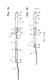
- Fig. 1A is a side view and Fig. 1B is a bottom plan view, in which a holding device according to one embodiment of the present invention is illustrated with its telescopic handle fully extended;
- Fig. 2A is a side view showing the telescopic handle in a partly retracted position and Fig. 2B is a side view showing the telescopic handle in a fully retracted position;
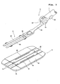
- Fig. 3 is a perspective view showing a support member of the holding device and a cleaning wiper to be attached thereto.
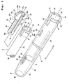
- Fig. 4 is an exploded perspective view of a portion indicated by IV in Fig. 1B ;
- Fig. 5 is an exploded perspective view for describing a portion indicated by V in Fig. 1B ;
- Figs. 6A and 6B are fragmentary sectional views taken along line VI-VI of Fig. 1A , showing locked and unlocked states;
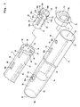
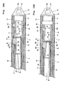
- Fig. 7 is an exploded perspective view for describing a portion indicated by VII in Fig. 1B ;
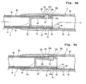
- Figs. 8A and 8B are fragmentary sectional views taken along line VIII-VIII of a Fig. 1A , showing locked and unlocked states;
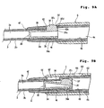
- Figs. 9A and 9B are fragmentary sectional views taken along line IX-IX of Fig. 2A , showing locked and unlocked states; and
- Figs. 10A and 10B are fragmentary sectional views taken along line X-X of Fig. 2B , showing locked and unlocked states.
- a cleaning tool comprises a holding device 1 generally shown in Figs. 1A, 1B , 2A and 2B and a cleaning wiper 9 shown in Fig. 3 .
- the holding device 1 comprises a telescopic handle 2 constructed of a first separate shaft 3, a second separate shaft 4 and a third separate shaft 5 that fit one within another and a support member 6 attached to a front end of the first separate shaft 3.
- the support member 6 comprises a support shaft 7 detachably attached to the first separate shaft 3 and a support body 8 pivotally attached to a front end of the support shaft 7.
- Individual components constituting the holding device 1 are all made of synthetic resin, such as ABS, vinyl chloride, PE (polyethylene), PP (polypropylene) and PET (polyethylene terephthalate).
- synthetic resin such as ABS, vinyl chloride, PE (polyethylene), PP (polypropylene) and PET (polyethylene terephthalate).
- PE polyethylene
- PP polypropylene
- PET polyethylene terephthalate
- at least a few of the components may be made of light metal such as aluminum or light alloy such as aluminum alloy.
- Y represents the extending direction of a shaft axis O of the telescopic handle 2 and the support shaft 7 in the holding device 1, wherein Y1 represents a front side of the holding device 1 which has the support member 6, while Y2 represents a rear side which has the third separate shaft 5.
- Fig. 4 shows a structure of the coupling between the first separate shaft 3 and the support shaft 7 (the portion indicated by IV in Fig. 1B ).
- the first separate shaft 3 is a hollow cylinder, so that a cylindrical internal space 3a extends axially inside of it.
- the first separate shaft 3 is integrally formed with an elastic arm 11 that extends forwardly (toward the Y1 side) of the holding device 1.
- a cut-out 12 is formed to communicate with the internal space 3a, thereby separating the elastic arm 11 from the main body portion of the first separate shaft 3.
- the elastic arm 11 has a supported end 11a on the rear side (Y2 side) and a free end 11b on the front side (Y1 side), wherein the free end 11b is elastically deformable toward the shaft axis O of the telescopic handle 2.
- the elastic arm 11 is integrally formed with an engaging projection 13 projecting outwardly beyond an outer periphery 3b of the first separate shaft 3.
- the engaging projection 13 has an outwardly curved end face 13a, wherein the end face 13a has, at its front side, a slope 13b that becomes closer to the shaft axis O as extending toward the Y1 side.
- the support shaft 7 is also a hollow cylinder having a cylindrical internal space 7a.
- the inner diameter of the support shaft 7 i.e., the diameter of the cylindrical internal space 7a
- an opening 7b is formed to communicate with the internal space 7a.
- the support shaft 7 has a through-hole 14 passing through the cylinder wall.
- the support shaft 7 has a depressed portion 15 in which the thickness of the cylinder wall is gradually decreased toward the periphery of the through-hole 14.
- the engaging projection 13 When the engaging projection 13 is aligned with the through-hole 14 by further insertion of the first separate shaft 3 into the support shaft 7, the engaging projection 13 fits within the through-hole 14 by an elastic restoring force of the elastic arm 11, thereby connecting the first separate shaft 3 and the support shaft 7 together.
- the end face 13a of the engaging projection 13 that is externally exposed through the through-hole 14 is pushed toward the shaft axis O by a fingertip.
- the first separate shaft 3 can be pulled out of the support shaft 7 with the engaging projection 13 released from the through-hole 14.
- the end face 13a of the engaging projection 13 can be easily pushed by a fingertip, and in addition, the engaging projection 13 can be easily released from the through-hole 14 due to the decreased thickness around the through-hole 14.
- Fig. 5 shows a structure of the coupling between the first separate shaft 3 and the second separate shaft 4 (the portion indicated by V in Fig. 1B ), wherein the first separate shaft 3 is illustrated only in its rear portion along with a locking member to be attached, while the second separate shaft 4 is illustrated almost as a whole.
- a circular opening 3d is formed to communicate with the internal space 3a.
- the first separate shaft 3 has a flange 3e projecting outwardly beyond the outer periphery 3b, within a predetermined range forwardly from the rear end face 3c.
- the flange 3e has an antirotation sliding recess 21 extending along the shaft axis O at a predetermined width.
- the first separate shaft 3 has a slot 22 extending forwardly from the rear end face 3c, at a location diametrically opposite the antirotation sliding recess 21.
- the slot 22 passing through the cylinder wall is open-ended at the rear end face 3c.
- positioning recesses 23, 23 shallowly recessed toward the Y1 side are formed at locations spaced 90 degrees apart from the antirotation sliding recess 21 and the slot 22.
- the locking member 30 has an outer periphery 31 that is dimensioned to have such an outer diameter as to permit insertion into the internal space 3a of the first separate shaft 3 without play.
- two positioning projections 33, 33 are formed to project radially.
- the width and the thickness in the Y direction of the positioning projections 33, 33 are substantially identical to the opening width and the depth of the positioning recesses 23, 23.
- the locking member 30 is integrally formed with an elastic arm 34 extending toward the rear side (Y2 side).
- the elastic arm 34 is integrally formed, at its free end, with an engaging projection (engaging claw) 34a that is directed outwardly.
- the first separate shaft 3 has an engaging hole 35 at a location spaced slightly forwardly apart from the rear end face 3c.
- the locking member 30 can be pulled out of the first separate shaft 3 by forcibly pushing the engaging projection 34a, which engages in the engaging hole 35, toward the shaft axis O from outside the first separate shaft 3 to release the fit.
- the engaging projection 34a and the engaging hole 35 constitute a fitting section for securing the locking member 30 without axial displacement.
- the locking member 30 is integrally formed with an elastic arm 36 extending along the shaft axis O, at a location spaced 180 degrees apart from the opposite elastic arm 34.
- the elastic arm 36 has a supported end 36a on the front side (Y1 side) and a free end 36b on the rear side (Y2 side).
- the elastic arm 36 is integrally formed with an engaging projection 37 projecting outwardly.
- the engaging projection 37 has a first engaging face 37a facing the rear side (Y2 side) and a second engaging face 37b facing the front side (Y1 side), wherein both the first engaging face 37a and the second engaging face 37b are substantially perpendicular to the shaft axis O.
- the engaging projection 37 also has an outwardly curved end face 37c.
- the end face 37c has a rear-side slope 37d whose projecting dimension beyond the outer periphery 3b is gradually decreased toward the first engaging face 37a.
- the end face 37c also has a front-side slope 37e whose projecting dimension is gradually decreased toward the second engaging face 37b.
- the second separate shaft 4 is a hollow cylinder whose inner diameter is relatively large over a relatively long range from a rear end face 4d toward the front side, thereby forming a large-diameter internal space 4a.
- the second separate shaft 4 is formed with a circular opening 4e communicating with the large-diameter internal space 4a.
- the second separate shaft 4 Over a short range from the front end face 4f toward the rear side, the second separate shaft 4 has a small-diameter internal space 4b whose diameter is slightly smaller than that of the large-diameter internal space 4a.
- a circular opening 4g communicating with the small-diameter internal space 4b.
- the diameter of the large-diameter internal space 4a is so set as to permit the flange 3e of the first separate shaft 3 to slide inside of it without play
- the diameter of the small-diameter internal space 4b is so set as to permit the outer periphery 3b of the first separate shaft 3 to slide inside of it without play.
- a shoulder between the large-diameter internal space 4a and the small-diameter internal space 4b functions as a stopper 4c.
- a ridge 41 is integrally formed to extend from the stopper 4c toward the rear side (Y2 side).
- the ridge 41 is dimensioned to slidingly fit in the antirotation sliding recess 21 formed in the flange 3e of the first separate shaft 3 without play.
- an elongated through-hole 42 is formed to pass through the cylinder wall and extend over a predetermined range from the vicinity of the stopper 4c toward the front side.
- the through-hole 42 has an engaging edge 42a on the rear side.
- the second separate shaft 4 On an outer periphery 4h, the second separate shaft 4 has a depressed portion 43 in which the thickness of the cylinder wall is gradually decreased toward the periphery of the through-hole 42.
- first separate shaft 3 cannot project any farther forwardly from the second separate shaft 4 when the flange 3e of the forwardly pulled first separate shaft 3 abuts against the stopper 4c, as shown in Fig. 6A .
- the engaging projection 37 of the locking member 30 enters the through-hole 42 formed in the second separate shaft 4.
- the end face 37c of the engaging projection 37 projects outwardly beyond the outer periphery 4h of the second separate shaft 4, as shown in Fig. 6A .
- the first engaging face 37a of the engaging projection 37 faces the engaging edge 42a of the through-hole 42.
- the projecting height h1 of the end face 37c of the engaging projection 37 beyond the outer periphery 4h of the second separate shaft 4 is slightly larger than the height h2 of the portion where the first engaging face 37a faces (engages) the engaging edge 42a. Accordingly, when the engaging projection 37 in the state of Fig. 6A is pushed down to make the end face 37c flush with the outer periphery 4h, the engagement of the first engaging face 37a with the engaging edge 42a is released, so that the rear-side slope 37d faces the engaging edge 42a of the through-hole 42.
- the first separate shaft 3 is accommodated in the second separate shaft 4 with the end face 37c of the engaging projection 37 sliding on the inner periphery of the second separate shaft 4 that defines the large-diameter internal space 4a, as shown in Fig. 6B .
- the elastic arm 36 formed in the locking member 30 has the free end 36b directed toward the rear side (Y2 side)
- the end face 37c of the engaging projection 37 is pushed toward the shaft axis O
- the first engaging face 37a on the free end moves toward the shaft axis O to take the lead, so that the engagement of the first engaging face 37a with the engaging edge 42a can be rapidly released.
- the first separate shaft 3 when the first separate shaft 3 is axially pushed into the second separate shaft 4 from the state where the rear-side slope 37d is in contact with the engaging edge 42a of the through-hole 42, the rear-side slope 37d facing toward the free end can easily move toward the shaft axis O. Accordingly, the first separate shaft 3 can be pushed into the second separate shaft 4 only with a slight pressure.
- Fig. 7 shows a structure of the coupling between the second separate shaft 4 and the third separate shaft 5 (the portion indicated by VII in Fig. 1B ), wherein the second separate shaft 4 is illustrated only in its rear portion along with a locking member to be attached, while the third separate shaft 5 is illustrated almost as a whole.
- the second separate shaft 4 has a flange 4i projecting outwardly beyond the outer periphery 4h, within a predetermined range from the rear end face 4c toward the front side.
- the flange 4i has an antirotation sliding recess 44 extending along the shaft axis O at a predetermined width.
- the second separate shaft 4 also has a slot 45 extending from the rear end face 4d toward the front side, at a location diametrically opposite the antirotation sliding recess 44.
- the slot 45 passing through the cylinder wall is open-ended at the rear end face 4d.
- positioning recesses 46, 46 shallowly recessed toward the Y1 side are formed at locations spaced 90 degrees apart from the antirotation sliding recess 44 and the slot 45.
- the locking member 50 has an outer periphery 51 that is dimensioned to have such an outer diameter as to permit insertion into the large-diameter internal space 4a of the second separate shaft 4 without play.
- two positioning projections 53, 53 are formed to project radially.
- the width and the thickness in the Y direction of the positioning projections 53, 53 are substantially equal to the width and the depth of the positioning recesses 46, 46.
- a projection 58 is integrally formed to project radially along the rear end face 52.
- the projection 58 has an antirotation sliding recess 58a extending axially at a predetermined width.
- the locking member 50 is integrally formed with an elastic arm 54 extending toward the rear side (Y2 side).
- the elastic arm 54 is integrally formed, at its free end, with an engaging projection (engaging claw) 54a that is directed outwardly.
- the second separate shaft 4 has an engaging hole 47 at a location spaced slightly forwardly apart from the rear end face 4d.
- the locking member 50 can be pulled out of the second separate shaft 4 by forcibly pushing the engaging projection 54a engaging in the engaging hole 47 toward the shaft axis O from outside the second separate shaft 4 to release the engagement between the engaging projection 54a and the engaging hole 47.
- the engaging projection 54a and the engaging hole 47 constitute a fitting section for securing the locking member 50 without axial displacement.
- the locking member 50 is integrally formed with an elastic arm 56 extending along the shaft axis O, at a location diametrically opposite the elastic arm 54.
- the elastic arm 56 has a supported end 56a on the front side (Y1 side) and a free end 56b on the rear side (Y2 side).
- the elastic arm 56 is integrally formed with an engaging projection 57 projecting outwardly.
- the engaging projection 57 has an engaging face 57a facing toward the rear side, wherein the engaging face 57a is substantially perpendicular to the shaft axis O.
- the engaging projection 57 also has an outwardly curved end face 57b, and the end face 57b has a slope 57c whose projecting height beyond the outer periphery 4h is gradually decreased toward the front side (Y1 side).
- the third separate shaft 5 is a hollow cylinder whose inner diameter is relatively large over a relatively long range from a rear end face 5d toward the front side, thereby forming a large-diameter internal space 5a.
- the third separate shaft 5 is formed with a circular opening 5e communicating with the large-diameter internal space 5a.
- the third separate shaft 5 Over a short range from a front end face 5f toward the rear side, the third separate shaft 5 has a small-diameter internal space 5b whose diameter is slightly smaller than that of the large-diameter internal space 5a.
- a circular opening 5g communicating with the small-diameter internal space 5b.
- the diameter of the large-diameter internal space 5a is so set as to permit the flange 4i of the second separate shaft 4 to slide inside of it without play
- the diameter of the small-diameter internal space 5b is so set as to permit the outer periphery 4h of the second separate shaft 4 to slide inside of it without play.
- a shoulder between the large-diameter internal space 5a and the small-diameter internal space 5b functions as a stopper 5c.
- a pair of ridges 61 and 62 are formed in diametrical opposed positions to extend from the stopper 5c toward the rear side (Y2 side).
- One ridge 61 is dimensioned such that the antirotation sliding recess 44 formed in the flange 4i of the second separate shaft 4 can slide on it without play.
- the other ridge 62 is dimensioned such that the antirotation sliding recess 58a formed in the locking member 50 can slide on it without play.
- a through-hole 63 is formed to pass through the cylinder wall on the front side.
- the third separate shaft 5 has a depressed portion 64 in which the thickness of the cylinder wall is gradually decreased toward the periphery of the through-hole 63.
- the through-hole 63 has an engaging edge 63a on the rear side.
- the front portion of the second separate shaft 4 projects forwardly from the opening 5g at the front end face 5f of the third separate shaft 5, as shown in Figs. 8A and 8B , and in such a state, the flange 4i of the second separate shaft 4 is permitted to slidingly move in the large-diameter internal space 5a of the third separate shaft 5, while the outer periphery 4h of the second separate shaft 4 is permitted to slidingly move in the small-diameter internal space 5b.
- the ridge 61 slidingly fits in the antirotation sliding recess 44 formed in the flange 4i, while the ridge 62 slidingly fits in the antirotation sliding recess 58a formed in the locking member 50. Due to the two ridges 61, 62 and the antirotation sliding recesses 44, 58a, the second separate shaft 4 can be axially slidingly accommodated in the third separate shaft 5 without rotation.
- the second separate shaft 4 cannot project any farther forwardly from the third separate shaft 5 when the flange 4i abuts against the stopper 5c, as shown in Fig. 8A .
- the engaging projection 57 formed in the locking member 50 enters the through-hole 63 formed in the third separate shaft 5.
- the end face 57b of the engaging projection 57 is exposed through the through-hole 63.
- the engaging face 57a of the engaging projection 57 faces the engaging edge 63a of the through-hole 63.
- the second separate shaft 4 projects farthest forwardly from the third separate shaft 5 with the engaging face 57a of the engaging projection 57 facing the engaging edge 63a of the through-hole 63, as shown in Fig. 8A , the second separate shaft 4 is engaged (locked) so as not to axially move toward the inside of the third separate shaft 5.
- the engaging face 57a is moved away from the engaging edge 63a by pushing the end face 57b of the engaging projection 57 toward the shaft axis O with a fingertip or the like.
- the engagement by the engaging projection 57 is released, and the second separate shaft 4 can be axially accommodated in the third separate shaft 5, as shown in Fig. 8B .
- the end face 57b of the engaging projection 57 slides on the ridge 62 formed on the inner periphery of the third separate shaft 5 that defines the large-diameter internal space 5a.
- a cap 70 fits in the third separate shaft 5.
- the cap 70 has a closing cylinder 71 to be pressed into the large-diameter internal space 5a through the opening 5e of the third separate shaft 5 and a cover 72 behind it.
- the cover 72 includes a hang member 73 defining a hang hole 73a. By handing the hang member 73 on a hook secured on the house wall or the like, the holding device 1 can be suspended.
- the second separate shaft 4 has a first hole 48 passing through the cylinder wall at a location spaced slightly forwardly apart from the slot 45.
- the first hole 48 is a slot elongated axially to have an engaging edge 48a on the front side.
- a second hole 65 and a third hole 66 which is closer to the rear end face 5d than the second hole 65, are formed to pass through the cylinder wall.
- the second hole 65 is an axially elongated slot, and its axial opening dimension is slightly smaller than that of the first hole 48.
- the third hole 66 is substantially circular.
- the second hole 65 has an engaging edge 65a on the front side
- the third hole 66 also has an engaging edge 66a on the front side.
- Fig. 10A is a sectional view taken along line X-X of Fig. 2B , showing the telescopic handle 2 in a fully retracted position.
- the second separate shaft 4 is fully pushed into the third separate shaft 5 toward the rear side.
- the engaging projection 57 formed in the locking member 50 enters the third hole 66.
- the slope 57c of the end face 57b of the engaging projection 57 faces the engaging edge 66a of the third hole 66. Accordingly, when a pulling force is applied forwardly to the second separate shaft 4 in this state, the slope 57 slides on the engaging edge 66a to deform the elastic arm 56 toward the shaft axis O, so that the engaging projection 57 comes out of the third hole 66 and the end face 57b of the engaging projection 57 slidingly contacts the inner periphery of the third separate shaft 5, as shown in Fig. 10B .
- the first separate shaft 3 is fully pushed into the second separate shaft 4 toward the rear side.
- the first hole 48 formed in the second separate shaft 4 faces the second hole 65 formed in the third separate shaft 5.
- the engaging projection 37 formed in the locking member 30 fits in the first hole 48 and faces into the second hole 65.
- the engaging edge 65a of the second hole 65 faces the front-side slope 37e of the end face 37c of the engaging projection 37.
- the engaging projection 57 provided in the second separate shaft 4 comes out of the third hole 66 to permit forward movement of the second separate shaft 4 within the third separate shaft 5, as set forth above.
- the front-side slope 37e of the engaging projection 37 provided in the first separate shaft 3 is pushed toward the shaft axis O by the engaging edge 65a of the second hole 65.
- the engaging projection 37 comes out of the second hole 65 to bring the end face 37c into sliding contact with the ridge 62 formed on the inner periphery of the third separate shaft 5, as shown in Fig. 10B .
- the engaging edge 48a of the first hole 48 of the second separate shaft 4 comes into contact with the front-side slope 37e of the engaging projection 37, so that the second separate shaft 4 is lightly locked to the first separate shaft 3.
- the first separate shaft 3 can consecutively project from the second separate shaft 4. After the first separate shaft 3 projects from the second separate shaft 4, then, the first separate shaft 3 and the second separate shaft 4 are locked to each other through the engaging projection 37.
- the outer periphery of the third separate shaft 5 may be covered with a cover tube 74 and/or a tape having a pressure-sensitive adhesive layer to close the second hole 65 and the third hole 66.
- the support body 8 is pivotally connected to the front end of the support shaft 7 through a pivot connection 81. Adjacent the pivot connection 81, a locking mechanism 82 is provided inside the support shaft 7. This locking mechanism 82 can lock the support body 8 at a variety of pivot angles.
- the support shaft 7 has an operating button 83, on its one side, for releasing the lock due to the locking mechanism 82.
- the support body 8 has an arm 84 extending forwardly from the pivot connection 81, and the arm 84 is bifurcated to provide support strips 85, 85 in the form of parallel flat plates. At the bifurcation point between the support strips 85, 85, a clip 86 is integrally formed to extend forwardly between the support strips 85, 85.
- the cleaning wiper 9 of Fig. 3 is a disposable, soft wiper, of which a main body 91 comprises a nonwoven fabric, a stack of nonwoven fabrics, a stack of papers, a foamed resin material, a stack of a nonwoven fabric and a bundle of fibers that is referred to as tow, or the like.
- a holding sheet 92 that comprises a nonwoven fabric or the like.
- the main body 91 and the holding sheet 92 are joined together at a pair of longitudinally extending side bond lines 93, 93 and a center bond line 94 extending parallel with and between the two side bond lines 93, 93.
- holding spaces 95, 95 individually defined between one side bond line 93 and the center bond line 94.
- the support strips 85, 85 of the support body 8 are inserted into the holding spaces 95, 95, the upper surface of the holding sheet 92 is pressed by the clip 86, whereby the cleaning wiper 9 attached to the support body 8 can be prevented from easily detaching therefrom.
- the holding device 1 can easily be assembled as follows:
- Figs. 1A and 1B show the telescopic handle 2 in a fully extended position, wherein the engaging projection 37 of the locking member 30 attached to the first separate shaft 3 is fittingly engaged (locked) to the through-hole 42 of the second separate shaft 4, as shown in Fig. 6A , while the engaging projection 57 of the locking member 50 attached to the second separate shaft 4 is fittingly engaged (locked) to the through-hole 63 of the third separate shaft 5, as shown in Fig. 8A .
- the engaging projection 57 which fits in the through-hole 63 formed in the third separate shaft 5 as shown in Fig. 8A , is first pushed by a finger. This releases the engagement between the second separate shaft 4 and the third separate shaft 5.
- the second separate shaft 4 is retracted into the third separate shaft 5 while the first separate shaft 3 and the second separate shaft 4 remain engaged through the engaging projection 37, wherein the end face 57b of the engaging projection 57 slides on the ridge 62 of the third separate shaft 5, as shown in Fig. 8B .
- the telescopic handle 2 can be changed from the fully extended position of Figs. 1A and 1B to the fully retracted position of Fig. 2B only with a rearward force kept applied to the support shaft 7 or the first separate shaft 3 even after the engagement between the second separate shaft 4 and the third separate shaft 5 is released by pushing the engaging projection 57.
- the engaging projection 57 provided at the rear portion of the second separate shaft 4 is engaged in and lightly locked to the third hole 66 of the third separate shaft 5, as shown in the X-X sectional view of Fig. 10A .
- the engaging projection 37 provided at the rear portion of the first separate shaft 3 is engaged in and locked to the first hole 48 formed in the second separate shaft 4, as well as faces into the second hole 65 formed in the third separate shaft 5.
- the antirotation sliding recess 44 is formed in the second separate shaft 4 and the antirotation sliding recess 58a is formed in the locking member 50 in Fig. 7
- the antirotation sliding recess 44 may be formed in the locking member 50 and the antirotation sliding recess 58a be formed in the second separate shaft 4.
- only one of the antirotation sliding recesses 44 and 58a may be provided.
- the antirotation sliding recess 21 may be formed in the locking member 30 or both the first separate shaft 3 and the locking member 30 may have antirotation sliding recesses.
- the axially extending ridge 41 is formed inside the second separate shaft 4, as shown in Fig. 5
- the axially extending ridges 61 and 62 are also formed inside the third separate shaft 5, as shown in Fig. 7 , but at least one of them may be axially extending groove, in place of ridge.
- the antirotation sliding recesses 21, 44, 58a are replaced by antirotation sliding projections for slidingly moving within the grooves.
- rear-side slope 37d and the front-side slope 37e formed in the engaging projection 37 may be straight slopes instead of curved slopes. This is true for the slope 57c of the engaging projection 57.
- the telescopic handle can be stabilized in both extended and retracted positions, and in addition, both extending and retracting operations of the handle can easily be performed.
Landscapes
- Engineering & Computer Science (AREA)
- Mechanical Engineering (AREA)
- Cleaning Implements For Floors, Carpets, Furniture, Walls, And The Like (AREA)
- Food-Manufacturing Devices (AREA)
- Purses, Travelling Bags, Baskets, Or Suitcases (AREA)
- Vehicle Cleaning, Maintenance, Repair, Refitting, And Outriggers (AREA)
- Mutual Connection Of Rods And Tubes (AREA)
Applications Claiming Priority (3)
| Application Number | Priority Date | Filing Date | Title |
|---|---|---|---|
| JP2002212756 | 2002-07-22 | ||
| JP2002212756A JP4302948B2 (ja) | 2002-07-22 | 2002-07-22 | 清掃用保持具およびその清掃用保持具を用いた清掃物品 |
| PCT/JP2003/009159 WO2004017806A1 (ja) | 2002-07-22 | 2003-07-18 | 保持具およびその保持具を用いた清掃物品 |
Publications (3)
| Publication Number | Publication Date |
|---|---|
| EP1523920A1 EP1523920A1 (en) | 2005-04-20 |
| EP1523920A4 EP1523920A4 (en) | 2007-01-24 |
| EP1523920B1 true EP1523920B1 (en) | 2008-11-05 |
Family
ID=31935593
Family Applications (1)
| Application Number | Title | Priority Date | Filing Date |
|---|---|---|---|
| EP03741483A Expired - Lifetime EP1523920B1 (en) | 2002-07-22 | 2003-07-18 | Holder and cleaning implement using the holder |
Country Status (16)
| Country | Link |
|---|---|
| US (1) | US7219386B2 (zh) |
| EP (1) | EP1523920B1 (zh) |
| JP (1) | JP4302948B2 (zh) |
| KR (1) | KR101004301B1 (zh) |
| CN (1) | CN100370943C (zh) |
| AR (1) | AR040610A1 (zh) |
| AT (1) | ATE413132T1 (zh) |
| AU (1) | AU2003290296B2 (zh) |
| CA (1) | CA2492667C (zh) |
| DE (1) | DE60324561D1 (zh) |
| EG (1) | EG24592A (zh) |
| ES (1) | ES2315513T3 (zh) |
| MX (1) | MXPA05000911A (zh) |
| MY (1) | MY134729A (zh) |
| TW (1) | TWI273899B (zh) |
| WO (1) | WO2004017806A1 (zh) |
Cited By (1)
| Publication number | Priority date | Publication date | Assignee | Title |
|---|---|---|---|---|
| US11628554B2 (en) | 2011-09-22 | 2023-04-18 | Resh, Inc. | Telepole apparatus and related methods |
Families Citing this family (101)
| Publication number | Priority date | Publication date | Assignee | Title |
|---|---|---|---|---|
| JPWO2005092171A1 (ja) * | 2004-03-29 | 2008-02-07 | 山田 千代恵 | 清掃具及びそれに用いる保持部材 |
| US20060010625A1 (en) * | 2004-07-14 | 2006-01-19 | Zuko, Llc | Cleansing system with disposable pads |
| DE102004047162A1 (de) * | 2004-09-29 | 2006-04-06 | Carl Freudenberg Kg | Stiel für ein Reinigungsgerät |
| US7346255B2 (en) * | 2004-11-15 | 2008-03-18 | Fujikura Ltd. | Tool for optical connector and tool equipped optical connector |
| US7891898B2 (en) * | 2005-01-28 | 2011-02-22 | S.C. Johnson & Son, Inc. | Cleaning pad for wet, damp or dry cleaning |
| US7802340B2 (en) | 2004-12-14 | 2010-09-28 | S.C. Johnson & Son, Inc. | Extendable cleaning implement having two support heads |
| US7740412B2 (en) | 2005-01-28 | 2010-06-22 | S.C. Johnson & Son, Inc. | Method of cleaning using a device with a liquid reservoir and replaceable non-woven pad |
| US7566671B2 (en) * | 2005-01-28 | 2009-07-28 | S.C. Johnson & Son, Inc. | Cleaning or dusting pad |
| US7976235B2 (en) | 2005-01-28 | 2011-07-12 | S.C. Johnson & Son, Inc. | Cleaning kit including duster and spray |
| US20060171767A1 (en) * | 2005-01-28 | 2006-08-03 | Hoadley David A | Cleaning device with liquid reservoir and replaceable non-woven pad |
| US20060230561A1 (en) * | 2005-04-19 | 2006-10-19 | Andre Sampaio | Duster with handle insert |
| US20060260082A1 (en) * | 2005-05-20 | 2006-11-23 | The Procter & Gamble Company | Cleaning implement |
| US7617560B2 (en) * | 2005-08-23 | 2009-11-17 | Randy Argo | Compact collapsible squeegee |
| ES2388746T3 (es) * | 2005-10-19 | 2012-10-18 | Kao Corporation | Utensilio de limpieza |
| US7716790B2 (en) * | 2005-12-22 | 2010-05-18 | Robert D. Newman, Jr. | On-the-go adjustable extension pole providing hands-free tool connection and disconnection |
| ES2397856T3 (es) * | 2006-03-09 | 2013-03-11 | Kao Corporation | Artículo de limpieza y método de producción |
| US20070212157A1 (en) * | 2006-03-13 | 2007-09-13 | Hoadley David A | Fringeless cleaning or dusting pad |
| US7650665B2 (en) | 2006-07-18 | 2010-01-26 | Kimberly-Clark Worlwide, Inc. | Mop assembly with fastener channels |
| US7624468B2 (en) * | 2006-07-18 | 2009-12-01 | Kimberly-Clark Worldwide, Inc. | Wet mop with multi-layer substrate |
| US7735182B2 (en) * | 2006-07-18 | 2010-06-15 | Kimberly-Clark Worldwide, Inc. | Mop assembly with reversible head |
| US7574768B2 (en) * | 2006-07-18 | 2009-08-18 | Kimberly-Clark Worldwide, Inc. | Quick-release handle and interchangeable cleaning system |
| US7655852B2 (en) * | 2006-07-27 | 2010-02-02 | Sullivan George V | Single reed woodwind musical instrument mouthpiece apparatus and method |
| US9643266B1 (en) * | 2006-10-27 | 2017-05-09 | Battenfeld Technologies, Inc. | Extendable folding saw |
| US8893347B2 (en) | 2007-02-06 | 2014-11-25 | S.C. Johnson & Son, Inc. | Cleaning or dusting pad with attachment member holder |
| US20080295779A1 (en) * | 2007-05-30 | 2008-12-04 | Dehoff Debra A | Cage cleaning device |
| GB0713898D0 (en) | 2007-07-17 | 2007-08-29 | Nexeon Ltd | A method of fabricating structured particles composed of silcon or a silicon-based material and their use in lithium rechargeable batteries |
| JP5052249B2 (ja) * | 2007-08-01 | 2012-10-17 | 花王株式会社 | 清掃具 |
| JP4922102B2 (ja) * | 2007-08-24 | 2012-04-25 | 花王株式会社 | 棒状具 |
| KR200445144Y1 (ko) | 2007-12-20 | 2009-07-02 | 조민수 | 다목적 3단 파괴기 |
| DE102009014681A1 (de) * | 2009-03-25 | 2010-09-30 | Leifheit Ag | Stiel, insbesondere Teleskopstiel zum Befestigen eines Arbeitsgeräts |
| TWM372694U (en) * | 2009-07-21 | 2010-01-21 | Younker Products Co Ltd | Cleaning tool |
| US8578564B2 (en) | 2009-11-05 | 2013-11-12 | The Procter & Gamble Company | Handle for removable cleaning implement |
| US10441120B1 (en) * | 2010-04-30 | 2019-10-15 | Unger Marketing International, Llc | Universal connecting members |
| GB2487730B (en) * | 2011-02-01 | 2014-05-14 | Lisa Lambert | Equine grooming device |
| FR2977468B1 (fr) * | 2011-07-05 | 2014-09-05 | Julien Jean Georges Coste | Dispositif de nettoyage repliable |
| JP5871555B2 (ja) * | 2011-10-14 | 2016-03-01 | 花王株式会社 | パイプの連結構造及びこれを用いた掃除具 |
| CN103040420B (zh) * | 2011-10-17 | 2015-11-25 | 杨雅菁 | 折叠式除尘掸 |
| JP2013119010A (ja) * | 2011-12-08 | 2013-06-17 | Nifco Inc | モップ取付用掃除具 |
| US20130234458A1 (en) * | 2012-02-24 | 2013-09-12 | Follow Thru, Llc | Zipper pulling tool |
| JP5894483B2 (ja) * | 2012-03-29 | 2016-03-30 | 花王株式会社 | 柄の連結構造 |
| JP5961425B2 (ja) * | 2012-03-30 | 2016-08-02 | ユニ・チャーム株式会社 | 清掃体ホルダ、清掃用具 |
| TW201340926A (zh) * | 2012-04-13 | 2013-10-16 | Ya-Jing Yang | 自動對摺變長變短的除塵撢手柄 |
| JP6062159B2 (ja) * | 2012-05-28 | 2017-01-18 | 株式会社ニトムズ | 伸縮シャフトおよび清掃具 |
| US9273763B2 (en) * | 2012-07-03 | 2016-03-01 | Elston Window & Wall, Llc | Systems and methods for unlocking/locking and opening/closing windows |
| ITMI20130294A1 (it) * | 2013-02-28 | 2014-08-29 | Nespoli Group S P A | Dispositivo di connessione per attrezzi |
| US8800113B1 (en) * | 2013-03-15 | 2014-08-12 | Blackstone Medical, Inc. | Rigid modular connector |
| TWI576079B (zh) * | 2013-03-28 | 2017-04-01 | Oimo Ind Co Ltd | Three-dimensional cyclone dust |
| US9138043B1 (en) | 2013-05-07 | 2015-09-22 | Virgil B. Meier | Universal container holder and means for application |
| JP6105425B2 (ja) * | 2013-07-25 | 2017-03-29 | 花王株式会社 | 棒状具 |
| JP6235829B2 (ja) * | 2013-08-19 | 2017-11-22 | 株式会社サニクリーン | 清掃具 |
| WO2015067317A1 (en) * | 2013-11-08 | 2015-05-14 | Husqvarna Ab | Coupling apparatus for telescoping tubes |
| CN104920087B (zh) * | 2014-03-17 | 2017-10-10 | 天佑电器(苏州)有限公司 | 一种延伸杆和具有该延伸杆的动力工具 |
| US10091948B2 (en) * | 2014-07-02 | 2018-10-09 | Wicked Tuff Gear, Llc | Light pole saw |
| US10945381B1 (en) | 2014-07-02 | 2021-03-16 | Outdoor Product Innovations, Inc. | Modular tools with detachable coupling |
| CN204140574U (zh) * | 2014-08-22 | 2015-02-04 | 奇立科技有限公司 | 伸缩管体及具有该伸缩管体的手杖及晒衣竿 |
| EP2995321B1 (en) | 2014-09-15 | 2017-07-26 | Procter & Gamble International Operations SA | A consumer goods product comprising chitin nanofibrils, lignin and a polymer or co-polymer |
| US20160106294A1 (en) | 2014-10-16 | 2016-04-21 | The Procter & Gamble Company | Kit having a package containing cleaning implements, package therefor and blank therefor |
| DE102014226484A1 (de) * | 2014-12-18 | 2016-06-23 | Mahle International Gmbh | Clipsverbindung |
| WO2016120878A1 (en) | 2015-01-29 | 2016-08-04 | Lil Monkey Ltd. | A spring for connecting a pipe to a connector |
| JP6486203B2 (ja) * | 2015-05-29 | 2019-03-20 | 河部精密工業株式会社 | 手動利器 |
| US9370282B1 (en) * | 2015-07-22 | 2016-06-21 | Paris Presents Incorporated | Bath brush with retractable handle |
| JP5976907B1 (ja) * | 2015-08-17 | 2016-08-24 | 株式会社コスモ精機 | バドミントン用シャトル |
| US10478865B2 (en) | 2015-12-15 | 2019-11-19 | The Procter & Gamble Company | Fibrous structures comprising regions having different solid additive levels |
| ES2866077T3 (es) | 2015-12-15 | 2021-10-19 | Procter & Gamble | Estructuras fibrosas prehumedecidas que presentan una mayor capacidad |
| EP3686343B1 (en) | 2015-12-15 | 2021-11-10 | The Procter & Gamble Company | Fibrous structures comprising three or more regions |
| WO2017106422A1 (en) | 2015-12-15 | 2017-06-22 | The Procter & Gamble Company | Compressible pre-moistened fibrous structures |
| US20170164808A1 (en) | 2015-12-15 | 2017-06-15 | The Procter & Gamble Company | Pre-Moistened Fibrous Structures Exhibiting Increased Mileage |
| US20170164809A1 (en) | 2015-12-15 | 2017-06-15 | The Procter & Gamble Company | Pre-Moistened Fibrous Structures |
| EP3702527B1 (en) | 2015-12-15 | 2021-10-27 | The Procter & Gamble Company | Fibrous structures comprising regions having different micro-ct intensive property values and associated transition slopes |
| US9963230B2 (en) | 2016-01-11 | 2018-05-08 | The Procter & Gamble Company | Aerial drone cleaning device and method of cleaning a target surface therewith |
| WO2017160899A1 (en) | 2016-03-15 | 2017-09-21 | The Procter & Gamble Company | Method and apparatus for manufacturing an absorbent article including an ultra short pulse laser source |
| US20170266941A1 (en) | 2016-03-15 | 2017-09-21 | The Procter & Gamble Company | Method and Apparatus for Manufacturing an Absorbent Article Including an Ultra Short Pulse Laser Source |
| EP3429526B1 (en) | 2016-03-15 | 2019-12-18 | The Procter and Gamble Company | Method and apparatus for manufacturing an absorbent article including an ultra short pulse laser source |
| JP6568004B2 (ja) * | 2016-03-31 | 2019-08-28 | グローブライド株式会社 | 玉網 |
| US10603779B2 (en) | 2016-07-12 | 2020-03-31 | Hemant Chandrakant Kurani | Adaptable pole for a pool device |
| US11172803B2 (en) | 2016-08-12 | 2021-11-16 | The Procter & Gamble Company | Cleaning sheets having coating thereon |
| JP6628708B2 (ja) * | 2016-09-13 | 2020-01-15 | ユニ・チャーム株式会社 | 清掃具 |
| CA3043527C (en) | 2016-12-08 | 2021-08-24 | The Procter & Gamble Company | Pre-moistened cleaning pads |
| US20180160874A1 (en) | 2016-12-08 | 2018-06-14 | The Procter & Gamble Company | Split core fibrous structures |
| US11622664B2 (en) | 2016-12-08 | 2023-04-11 | The Procter & Gamble Company | Fibrous structures having a contact surface |
| CN106765223A (zh) * | 2016-12-22 | 2017-05-31 | 安徽天利粮油集团股份有限公司 | 用于烟囱清洁的连接头 |
| CN106765237A (zh) * | 2016-12-22 | 2017-05-31 | 安徽天利粮油集团股份有限公司 | 用于壁炉管道清洁的棒子 |
| JP6469073B2 (ja) * | 2016-12-28 | 2019-02-13 | ユニ・チャーム株式会社 | 清掃具 |
| JP6879757B2 (ja) * | 2017-02-08 | 2021-06-02 | ユニ・チャーム株式会社 | 清掃具用のアーム部 |
| US10787835B2 (en) * | 2017-03-05 | 2020-09-29 | Beach House Group Limited | Play structure tube connector and system |
| CN107192797A (zh) * | 2017-07-19 | 2017-09-22 | 常州合众电气有限公司 | 六氟化硫气体浓度检测仪 |
| WO2019113264A1 (en) | 2017-12-07 | 2019-06-13 | The Procter & Gamble Company | Flexible bonding |
| US11333182B2 (en) * | 2018-03-12 | 2022-05-17 | James R. Conrad | Telescopic pole and locking mechanism |
| JP6567116B1 (ja) * | 2018-03-20 | 2019-08-28 | ユニ・チャーム株式会社 | 清掃具用のアーム部 |
| FR3081842B1 (fr) * | 2018-05-29 | 2021-05-21 | Arianegroup Sas | Moyens de verrouillage et de retenue de segments de dispositif porteur deployable et dispositif porteur deployable les comprenant |
| JP7274829B2 (ja) * | 2018-06-29 | 2023-05-17 | 株式会社ダスキン | ボタン式清掃具 |
| CN108937763B (zh) * | 2018-07-16 | 2020-09-29 | 佛山市高明区杨和金属材料专业镇技术创新中心 | 一种多功能扫把 |
| JP7268978B2 (ja) * | 2018-08-30 | 2023-05-08 | 大王製紙株式会社 | 清掃具用柄及び清掃具 |
| US11389986B2 (en) | 2018-12-06 | 2022-07-19 | The Procter & Gamble Company | Compliant anvil |
| US11744432B1 (en) * | 2019-05-06 | 2023-09-05 | Contec Inc. | Adjustable dusting tool and related method |
| US20210022327A1 (en) * | 2019-07-17 | 2021-01-28 | Michael Barber | Telescoping pole spear |
| US11143229B1 (en) * | 2020-11-13 | 2021-10-12 | Rodger Gabriel Marchisset | Biasing positioning element |
| JP7482004B2 (ja) * | 2020-11-26 | 2024-05-13 | 株式会社マキタ | 作業機 |
| KR102494417B1 (ko) * | 2020-12-16 | 2023-02-06 | 박현욱 | 청소용구의 손잡이 스틱 |
| CN114321608A (zh) * | 2022-01-04 | 2022-04-12 | 上海航天电子通讯设备研究所 | 一种电动升降杆 |
| EP4299254A1 (en) * | 2022-07-01 | 2024-01-03 | Filmop International s.r.l. | Telescopic handle with anti-slip device |
Family Cites Families (27)
| Publication number | Priority date | Publication date | Assignee | Title |
|---|---|---|---|---|
| US2134301A (en) * | 1936-03-12 | 1938-10-25 | Carl F Guggenbuehler | Universal utility extension mop |
| JPS49147874U (zh) | 1973-04-16 | 1974-12-20 | ||
| JPS5094037A (zh) | 1973-12-24 | 1975-07-26 | ||
| JPS50155857A (zh) | 1974-06-07 | 1975-12-16 | ||
| JPS5185273A (ja) | 1975-01-22 | 1976-07-26 | Takeshi Abiru | Burashihorudaa |
| JPS54116960A (en) | 1978-03-03 | 1979-09-11 | Hitachi Ltd | Electromagnetic flow meter |
| JPS5713183A (en) | 1980-06-26 | 1982-01-23 | Chlorine Eng Corp Ltd | Method for recovering amino acid and caustic alkali from alkali salt of amino acid |
| DE3234704A1 (de) * | 1982-09-18 | 1984-03-22 | Roman Dietsche KG, 7868 Todtnau | Besen, schrubber od. dgl. mit am buerstenkoerper loesbar befestigtem stiel |
| JP3057754B2 (ja) | 1990-11-22 | 2000-07-04 | 日本電気株式会社 | メモリ回路および分散処理システム |
| US5305882A (en) * | 1991-12-10 | 1994-04-26 | Kaplan Alan F | Self-storing collapsible implement |
| CN2179742Y (zh) * | 1994-01-20 | 1994-10-19 | 林耿男 | 具有拧干装置之拖把 |
| CN2193304Y (zh) * | 1994-05-04 | 1995-03-29 | 丰含午 | 自行车伞夹持器 |
| US5593196A (en) * | 1994-11-29 | 1997-01-14 | Hastings Fiber Glass Products, Inc. | Telescopic hot stick |
| JP2977477B2 (ja) | 1995-12-08 | 1999-11-15 | 花王株式会社 | 清掃具 |
| JPH0938009A (ja) | 1995-08-01 | 1997-02-10 | Kao Corp | 清掃布、清掃具の柄及び清掃具 |
| ES2175111T3 (es) * | 1995-08-01 | 2002-11-16 | Kao Corp | Paño para limpiar y aparato de limpieza. |
| CA2199701A1 (en) * | 1996-06-13 | 1997-12-13 | Invacare Corporation | Integral snap button and anti-rattle member |
| JPH1043116A (ja) * | 1996-08-05 | 1998-02-17 | Kao Corp | 清掃具の柄 |
| JP3666772B2 (ja) | 1997-02-26 | 2005-06-29 | 花王株式会社 | 伸縮棒状具 |
| US6213672B1 (en) * | 1997-10-21 | 2001-04-10 | George J. Varga | Telescoping pole & cleaning tool |
| JPH11123672A (ja) | 1997-10-24 | 1999-05-11 | Kao Corp | 伸縮棒状具 |
| JP2000046021A (ja) | 1998-07-30 | 2000-02-15 | Teramoto Corp | 伸縮ロッドおよびこの伸縮ロッドを用いた柄付き用具 |
| JP4170477B2 (ja) | 1998-11-17 | 2008-10-22 | 寛 藤田 | 掃除具 |
| US6123672A (en) * | 1998-12-31 | 2000-09-26 | General Electric Company | Color flow imaging for enhancing segmentation and flow dynamics |
| US6371686B1 (en) * | 2000-06-28 | 2002-04-16 | Tsun-Zong Wu | Central shaft for collapsible umbrella |
| JP2002017640A (ja) | 2000-07-04 | 2002-01-22 | Teramoto Corp | 清掃用具のヘッドホルダ |
| IL152340A (en) * | 2001-02-23 | 2007-12-03 | Yoshinori Tanaka | Cleaning accessory |
-
2002
- 2002-07-22 JP JP2002212756A patent/JP4302948B2/ja not_active Expired - Lifetime
-
2003
- 2003-07-17 MY MYPI20032692A patent/MY134729A/en unknown
- 2003-07-18 EP EP03741483A patent/EP1523920B1/en not_active Expired - Lifetime
- 2003-07-18 MX MXPA05000911A patent/MXPA05000911A/es active IP Right Grant
- 2003-07-18 CN CNB038164310A patent/CN100370943C/zh not_active Expired - Fee Related
- 2003-07-18 CA CA002492667A patent/CA2492667C/en not_active Expired - Lifetime
- 2003-07-18 AU AU2003290296A patent/AU2003290296B2/en not_active Ceased
- 2003-07-18 DE DE60324561T patent/DE60324561D1/de not_active Expired - Lifetime
- 2003-07-18 ES ES03741483T patent/ES2315513T3/es not_active Expired - Lifetime
- 2003-07-18 AT AT03741483T patent/ATE413132T1/de not_active IP Right Cessation
- 2003-07-18 WO PCT/JP2003/009159 patent/WO2004017806A1/ja active Application Filing
- 2003-07-18 TW TW092119688A patent/TWI273899B/zh not_active IP Right Cessation
- 2003-07-18 KR KR1020057001089A patent/KR101004301B1/ko active IP Right Grant
- 2003-07-21 AR AR20030102612A patent/AR040610A1/es active IP Right Grant
- 2003-07-22 EG EG2003070714A patent/EG24592A/xx active
-
2004
- 2004-12-14 US US11/012,972 patent/US7219386B2/en not_active Expired - Lifetime
Cited By (1)
| Publication number | Priority date | Publication date | Assignee | Title |
|---|---|---|---|---|
| US11628554B2 (en) | 2011-09-22 | 2023-04-18 | Resh, Inc. | Telepole apparatus and related methods |
Also Published As
| Publication number | Publication date |
|---|---|
| CA2492667C (en) | 2009-06-02 |
| US7219386B2 (en) | 2007-05-22 |
| MY134729A (en) | 2007-12-31 |
| AR040610A1 (es) | 2005-04-13 |
| KR101004301B1 (ko) | 2010-12-28 |
| AU2003290296A1 (en) | 2004-03-11 |
| MXPA05000911A (es) | 2005-03-23 |
| EP1523920A4 (en) | 2007-01-24 |
| DE60324561D1 (de) | 2008-12-18 |
| TW200403038A (en) | 2004-03-01 |
| ES2315513T3 (es) | 2009-04-01 |
| US20050097691A1 (en) | 2005-05-12 |
| JP4302948B2 (ja) | 2009-07-29 |
| KR20050026501A (ko) | 2005-03-15 |
| CA2492667A1 (en) | 2004-03-04 |
| AU2003290296B2 (en) | 2009-07-30 |
| TWI273899B (en) | 2007-02-21 |
| EG24592A (en) | 2009-12-08 |
| CN1668239A (zh) | 2005-09-14 |
| JP2004049628A (ja) | 2004-02-19 |
| WO2004017806A1 (ja) | 2004-03-04 |
| EP1523920A1 (en) | 2005-04-20 |
| CN100370943C (zh) | 2008-02-27 |
| ATE413132T1 (de) | 2008-11-15 |
Similar Documents
| Publication | Publication Date | Title |
|---|---|---|
| EP1523920B1 (en) | Holder and cleaning implement using the holder | |
| JP5154985B2 (ja) | 光コネクタプラグ | |
| KR101004306B1 (ko) | 유지구 및 이러한 유지구를 이용한 청소 물품 | |
| US6286742B1 (en) | Nail driving tool | |
| JP4662746B2 (ja) | 補助グリップハンドル用ピン無しダンパー組立体 | |
| SK287062B6 (sk) | Holiaci strojček zahŕňajúci rukoväť a výmennú hlavicu | |
| US20090000085A1 (en) | Fastener | |
| CN108883542B (zh) | 具有用于接合与脱离剃须刀架的锁定和释放机构的剃须刀手柄 | |
| US20060068642A1 (en) | Attaching member to panel hole, and clamping tool | |
| US5152626A (en) | Writing pen with retractable clip | |
| EP1872968B1 (en) | Slide pen | |
| JP2002350677A (ja) | プラグ挿着具、プラグ抜脱具及びそれらを備えたプラグ着脱具 | |
| JP2007082723A (ja) | パイプの連結構造 | |
| JPS586640B2 (ja) | ヨコホウコウニカドウナ クリツプオユウスルヒツキグ | |
| JP5759645B1 (ja) | 両面押ボタン幅薄型払拭体保持具及び清掃具 | |
| JP2013204762A (ja) | 柄の連結構造 | |
| JP2005266088A (ja) | 光コネクタ | |
| JP2527418Y2 (ja) | ノック式筆記具 | |
| WO2023228672A1 (ja) | 綴じ具、及び、ファイル | |
| JP3889405B2 (ja) | 光コネクタ | |
| JP7527139B2 (ja) | 磁気吸引具およびインサート装置 | |
| JP2601606B2 (ja) | 刃体出没式カッターナイフにおけるホルダの構造 | |
| JP3214692U (ja) | 布地手入れ用具 | |
| JP2008043599A (ja) | カートリッジ式カッターナイフ | |
| JPH07204363A (ja) | カッターナイフ |
Legal Events
| Date | Code | Title | Description |
|---|---|---|---|
| PUAI | Public reference made under article 153(3) epc to a published international application that has entered the european phase |
Free format text: ORIGINAL CODE: 0009012 |
|
| 17P | Request for examination filed |
Effective date: 20041209 |
|
| AK | Designated contracting states |
Kind code of ref document: A1 Designated state(s): AT BE BG CH CY CZ DE DK EE ES FI FR GB GR HU IE IT LI LU MC NL PT RO SE SI SK TR |
|
| AX | Request for extension of the european patent |
Extension state: AL LT LV MK |
|
| DAX | Request for extension of the european patent (deleted) | ||
| A4 | Supplementary search report drawn up and despatched |
Effective date: 20061228 |
|
| RIC1 | Information provided on ipc code assigned before grant |
Ipc: A47L 13/38 20060101ALI20061220BHEP Ipc: A47L 13/24 20060101ALI20061220BHEP Ipc: F16B 7/10 20060101ALI20061220BHEP Ipc: A47L 13/20 20060101AFI20040317BHEP Ipc: B25G 1/04 20060101ALI20061220BHEP Ipc: B25G 3/18 20060101ALI20061220BHEP |
|
| 17Q | First examination report despatched |
Effective date: 20070413 |
|
| GRAP | Despatch of communication of intention to grant a patent |
Free format text: ORIGINAL CODE: EPIDOSNIGR1 |
|
| GRAS | Grant fee paid |
Free format text: ORIGINAL CODE: EPIDOSNIGR3 |
|
| GRAA | (expected) grant |
Free format text: ORIGINAL CODE: 0009210 |
|
| AK | Designated contracting states |
Kind code of ref document: B1 Designated state(s): AT BE BG CH CY CZ DE DK EE ES FI FR GB GR HU IE IT LI LU MC NL PT RO SE SI SK TR |
|
| REG | Reference to a national code |
Ref country code: GB Ref legal event code: FG4D |
|
| REG | Reference to a national code |
Ref country code: CH Ref legal event code: EP |
|
| REG | Reference to a national code |
Ref country code: IE Ref legal event code: FG4D |
|
| REF | Corresponds to: |
Ref document number: 60324561 Country of ref document: DE Date of ref document: 20081218 Kind code of ref document: P |
|
| REG | Reference to a national code |
Ref country code: GR Ref legal event code: EP Ref document number: 20080403471 Country of ref document: GR |
|
| REG | Reference to a national code |
Ref country code: SE Ref legal event code: TRGR |
|
| REG | Reference to a national code |
Ref country code: ES Ref legal event code: FG2A Ref document number: 2315513 Country of ref document: ES Kind code of ref document: T3 |
|
| PG25 | Lapsed in a contracting state [announced via postgrant information from national office to epo] |
Ref country code: AT Free format text: LAPSE BECAUSE OF FAILURE TO SUBMIT A TRANSLATION OF THE DESCRIPTION OR TO PAY THE FEE WITHIN THE PRESCRIBED TIME-LIMIT Effective date: 20081105 |
|
| PG25 | Lapsed in a contracting state [announced via postgrant information from national office to epo] |
Ref country code: SI Free format text: LAPSE BECAUSE OF FAILURE TO SUBMIT A TRANSLATION OF THE DESCRIPTION OR TO PAY THE FEE WITHIN THE PRESCRIBED TIME-LIMIT Effective date: 20081105 Ref country code: FI Free format text: LAPSE BECAUSE OF FAILURE TO SUBMIT A TRANSLATION OF THE DESCRIPTION OR TO PAY THE FEE WITHIN THE PRESCRIBED TIME-LIMIT Effective date: 20081105 |
|
| PG25 | Lapsed in a contracting state [announced via postgrant information from national office to epo] |
Ref country code: BG Free format text: LAPSE BECAUSE OF FAILURE TO SUBMIT A TRANSLATION OF THE DESCRIPTION OR TO PAY THE FEE WITHIN THE PRESCRIBED TIME-LIMIT Effective date: 20090205 Ref country code: RO Free format text: LAPSE BECAUSE OF FAILURE TO SUBMIT A TRANSLATION OF THE DESCRIPTION OR TO PAY THE FEE WITHIN THE PRESCRIBED TIME-LIMIT Effective date: 20081105 Ref country code: DK Free format text: LAPSE BECAUSE OF FAILURE TO SUBMIT A TRANSLATION OF THE DESCRIPTION OR TO PAY THE FEE WITHIN THE PRESCRIBED TIME-LIMIT Effective date: 20081105 Ref country code: EE Free format text: LAPSE BECAUSE OF FAILURE TO SUBMIT A TRANSLATION OF THE DESCRIPTION OR TO PAY THE FEE WITHIN THE PRESCRIBED TIME-LIMIT Effective date: 20081105 |
|
| PG25 | Lapsed in a contracting state [announced via postgrant information from national office to epo] |
Ref country code: PT Free format text: LAPSE BECAUSE OF FAILURE TO SUBMIT A TRANSLATION OF THE DESCRIPTION OR TO PAY THE FEE WITHIN THE PRESCRIBED TIME-LIMIT Effective date: 20090406 |
|
| PLBE | No opposition filed within time limit |
Free format text: ORIGINAL CODE: 0009261 |
|
| STAA | Information on the status of an ep patent application or granted ep patent |
Free format text: STATUS: NO OPPOSITION FILED WITHIN TIME LIMIT |
|
| REG | Reference to a national code |
Ref country code: HU Ref legal event code: AG4A Ref document number: E005626 Country of ref document: HU |
|
| 26N | No opposition filed |
Effective date: 20090806 |
|
| PG25 | Lapsed in a contracting state [announced via postgrant information from national office to epo] |
Ref country code: MC Free format text: LAPSE BECAUSE OF NON-PAYMENT OF DUE FEES Effective date: 20090731 |
|
| REG | Reference to a national code |
Ref country code: CH Ref legal event code: PL |
|
| EUG | Se: european patent has lapsed | ||
| PG25 | Lapsed in a contracting state [announced via postgrant information from national office to epo] |
Ref country code: LI Free format text: LAPSE BECAUSE OF NON-PAYMENT OF DUE FEES Effective date: 20090731 Ref country code: CH Free format text: LAPSE BECAUSE OF NON-PAYMENT OF DUE FEES Effective date: 20090731 |
|
| PG25 | Lapsed in a contracting state [announced via postgrant information from national office to epo] |
Ref country code: SE Free format text: LAPSE BECAUSE OF NON-PAYMENT OF DUE FEES Effective date: 20090719 |
|
| PG25 | Lapsed in a contracting state [announced via postgrant information from national office to epo] |
Ref country code: TR Free format text: LAPSE BECAUSE OF FAILURE TO SUBMIT A TRANSLATION OF THE DESCRIPTION OR TO PAY THE FEE WITHIN THE PRESCRIBED TIME-LIMIT Effective date: 20081105 |
|
| PG25 | Lapsed in a contracting state [announced via postgrant information from national office to epo] |
Ref country code: CY Free format text: LAPSE BECAUSE OF FAILURE TO SUBMIT A TRANSLATION OF THE DESCRIPTION OR TO PAY THE FEE WITHIN THE PRESCRIBED TIME-LIMIT Effective date: 20081105 |
|
| REG | Reference to a national code |
Ref country code: FR Ref legal event code: PLFP Year of fee payment: 14 |
|
| REG | Reference to a national code |
Ref country code: FR Ref legal event code: PLFP Year of fee payment: 15 |
|
| REG | Reference to a national code |
Ref country code: FR Ref legal event code: PLFP Year of fee payment: 16 |
|
| PGFP | Annual fee paid to national office [announced via postgrant information from national office to epo] |
Ref country code: GR Payment date: 20200610 Year of fee payment: 18 |
|
| PGFP | Annual fee paid to national office [announced via postgrant information from national office to epo] |
Ref country code: NL Payment date: 20200615 Year of fee payment: 18 Ref country code: BE Payment date: 20200617 Year of fee payment: 18 Ref country code: SK Payment date: 20200617 Year of fee payment: 18 |
|
| PGFP | Annual fee paid to national office [announced via postgrant information from national office to epo] |
Ref country code: ES Payment date: 20200803 Year of fee payment: 18 Ref country code: LU Payment date: 20200710 Year of fee payment: 18 Ref country code: IE Payment date: 20200709 Year of fee payment: 18 Ref country code: CZ Payment date: 20200716 Year of fee payment: 18 |
|
| PGFP | Annual fee paid to national office [announced via postgrant information from national office to epo] |
Ref country code: HU Payment date: 20200614 Year of fee payment: 18 |
|
| PGFP | Annual fee paid to national office [announced via postgrant information from national office to epo] |
Ref country code: FR Payment date: 20210611 Year of fee payment: 19 Ref country code: IT Payment date: 20210610 Year of fee payment: 19 |
|
| PGFP | Annual fee paid to national office [announced via postgrant information from national office to epo] |
Ref country code: GB Payment date: 20210623 Year of fee payment: 19 |
|
| PGFP | Annual fee paid to national office [announced via postgrant information from national office to epo] |
Ref country code: DE Payment date: 20210622 Year of fee payment: 19 |
|
| REG | Reference to a national code |
Ref country code: NL Ref legal event code: MM Effective date: 20210801 |
|
| REG | Reference to a national code |
Ref country code: BE Ref legal event code: MM Effective date: 20210731 |
|
| REG | Reference to a national code |
Ref country code: SK Ref legal event code: MM4A Ref document number: E 4665 Country of ref document: SK Effective date: 20210718 |
|
| PG25 | Lapsed in a contracting state [announced via postgrant information from national office to epo] |
Ref country code: HU Free format text: LAPSE BECAUSE OF NON-PAYMENT OF DUE FEES Effective date: 20210719 |
|
| PG25 | Lapsed in a contracting state [announced via postgrant information from national office to epo] |
Ref country code: SK Free format text: LAPSE BECAUSE OF NON-PAYMENT OF DUE FEES Effective date: 20210718 Ref country code: NL Free format text: LAPSE BECAUSE OF NON-PAYMENT OF DUE FEES Effective date: 20210801 Ref country code: LU Free format text: LAPSE BECAUSE OF NON-PAYMENT OF DUE FEES Effective date: 20210718 Ref country code: GR Free format text: LAPSE BECAUSE OF NON-PAYMENT OF DUE FEES Effective date: 20220207 Ref country code: CZ Free format text: LAPSE BECAUSE OF NON-PAYMENT OF DUE FEES Effective date: 20210718 |
|
| PG25 | Lapsed in a contracting state [announced via postgrant information from national office to epo] |
Ref country code: IE Free format text: LAPSE BECAUSE OF NON-PAYMENT OF DUE FEES Effective date: 20210718 Ref country code: BE Free format text: LAPSE BECAUSE OF NON-PAYMENT OF DUE FEES Effective date: 20210731 |
|
| REG | Reference to a national code |
Ref country code: ES Ref legal event code: FD2A Effective date: 20220831 |
|
| PG25 | Lapsed in a contracting state [announced via postgrant information from national office to epo] |
Ref country code: ES Free format text: LAPSE BECAUSE OF NON-PAYMENT OF DUE FEES Effective date: 20210719 |
|
| REG | Reference to a national code |
Ref country code: DE Ref legal event code: R119 Ref document number: 60324561 Country of ref document: DE |
|
| GBPC | Gb: european patent ceased through non-payment of renewal fee |
Effective date: 20220718 |
|
| PG25 | Lapsed in a contracting state [announced via postgrant information from national office to epo] |
Ref country code: FR Free format text: LAPSE BECAUSE OF NON-PAYMENT OF DUE FEES Effective date: 20220731 |
|
| PG25 | Lapsed in a contracting state [announced via postgrant information from national office to epo] |
Ref country code: GB Free format text: LAPSE BECAUSE OF NON-PAYMENT OF DUE FEES Effective date: 20220718 Ref country code: DE Free format text: LAPSE BECAUSE OF NON-PAYMENT OF DUE FEES Effective date: 20230201 |
|
| PG25 | Lapsed in a contracting state [announced via postgrant information from national office to epo] |
Ref country code: IT Free format text: LAPSE BECAUSE OF NON-PAYMENT OF DUE FEES Effective date: 20220718 |