EP1522660B1 - Falle, insbesondere Rollenfalle sowie Schloss mit einer derartigen Falle - Google Patents
Falle, insbesondere Rollenfalle sowie Schloss mit einer derartigen Falle Download PDFInfo
- Publication number
- EP1522660B1 EP1522660B1 EP04104532A EP04104532A EP1522660B1 EP 1522660 B1 EP1522660 B1 EP 1522660B1 EP 04104532 A EP04104532 A EP 04104532A EP 04104532 A EP04104532 A EP 04104532A EP 1522660 B1 EP1522660 B1 EP 1522660B1
- Authority
- EP
- European Patent Office
- Prior art keywords
- latch bolt
- face plate
- lock
- plate opening
- latch
- Prior art date
- Legal status (The legal status is an assumption and is not a legal conclusion. Google has not performed a legal analysis and makes no representation as to the accuracy of the status listed.)
- Expired - Lifetime
Links
- 238000003780 insertion Methods 0.000 claims abstract description 13
- 230000037431 insertion Effects 0.000 claims abstract description 13
- 210000002105 tongue Anatomy 0.000 claims description 10
- 210000003128 head Anatomy 0.000 description 11
- 230000008878 coupling Effects 0.000 description 5
- 238000010168 coupling process Methods 0.000 description 5
- 238000005859 coupling reaction Methods 0.000 description 5
- 230000007246 mechanism Effects 0.000 description 3
- 230000009467 reduction Effects 0.000 description 3
- 230000008859 change Effects 0.000 description 2
- 239000000463 material Substances 0.000 description 2
- 238000005299 abrasion Methods 0.000 description 1
- 230000008901 benefit Effects 0.000 description 1
- 230000001747 exhibiting effect Effects 0.000 description 1
- 210000001061 forehead Anatomy 0.000 description 1
- 238000007654 immersion Methods 0.000 description 1
- 230000000149 penetrating effect Effects 0.000 description 1
- 230000035939 shock Effects 0.000 description 1
Images

Classifications
-
- E—FIXED CONSTRUCTIONS
- E05—LOCKS; KEYS; WINDOW OR DOOR FITTINGS; SAFES
- E05B—LOCKS; ACCESSORIES THEREFOR; HANDCUFFS
- E05B63/00—Locks or fastenings with special structural characteristics
- E05B63/06—Locks or fastenings with special structural characteristics with lengthwise-adjustable bolts ; with adjustable backset, i.e. distance from door edge
-
- E—FIXED CONSTRUCTIONS
- E05—LOCKS; KEYS; WINDOW OR DOOR FITTINGS; SAFES
- E05B—LOCKS; ACCESSORIES THEREFOR; HANDCUFFS
- E05B59/00—Locks with latches separate from the lock-bolts or with a plurality of latches or lock-bolts
-
- E—FIXED CONSTRUCTIONS
- E05—LOCKS; KEYS; WINDOW OR DOOR FITTINGS; SAFES
- E05B—LOCKS; ACCESSORIES THEREFOR; HANDCUFFS
- E05B63/00—Locks or fastenings with special structural characteristics
- E05B63/0056—Locks with adjustable or exchangeable lock parts
-
- E—FIXED CONSTRUCTIONS
- E05—LOCKS; KEYS; WINDOW OR DOOR FITTINGS; SAFES
- E05B—LOCKS; ACCESSORIES THEREFOR; HANDCUFFS
- E05B65/00—Locks or fastenings for special use
- E05B65/06—Locks or fastenings for special use for swing doors or windows, i.e. opening inwards and outwards
Definitions
- the invention relates to a trap according to the preamble of claim 1 and a lock according to the preamble of claim 9.
- a generic case is from the US 3,197,247 previously known.
- the housing has an end face which rests against the back of the forend when mounted.
- the end face of the housing has an opening in which a trap is guided. In the trapping position, the trap extends through a cuff opening. In this face opening also extends a flange extending along the opening edge of the face plate opening.
- the DE 42 18 733 A1 describes a lock with a roller latch, wherein the case head is seated in a housing which is displaceable against a rearward of the forehead mountable carrier against the restoring force of a latch spring.
- the invention has for its object to improve a generic case or to create a generic castle of increased utility value.
- the insert part has a basic contour, which is adapted to the basic contour of the standardized cuff opening of the lock.
- This is particularly important in the case of the lock designed as mortise lock insofar as such a lock is generally equipped with a standardized wedge trap penetrating the face opening.
- the latter are, as known from the prior art, detachable from the lock mechanism of the lock to possibly use one and the same lock by turning the wedge trap for left or right hinged doors.
- a relation to the wedge trap smaller dimensioned case, which can be inserted into the Stulpö réelle insert part is provided.
- the insert part which is adapted to the standardized cuff opening advantageously serves practically as an adapter for the lesser-dimensioned trap arranged in the insert part.
- the range of use of a generic castle is substantially increased.
- a cost-effective storage is achieved hereby.
- the arranged in the insert part case is designed as a roller trap. More preferably, it is provided that the stop is a firmly connected to the case head projection. It is also advantageous that the means for adjusting the depth stop are assigned to the insert part, wherein the counter-stop formed by the insert part is depth-adjustable.
- the counter-stop is formed by a spindle nut, which is seated on a spindle spindle accessible from the side of the cowl and rotatable relative to the insert.
- a spindle nut which is seated on a spindle spindle accessible from the side of the cowl and rotatable relative to the insert.
- the insert consists of plastic, the latter being einklippsbar in the Stulpö réelle, which, due to the plastic material, if necessary, a metallic abrasion of the wall edges of the face opening is counteracted in an advantageous manner.
- a further advantage results from the measure that one bearing end of the spindle is mounted in the bottom of a spindle bearing recess of the insert part and that the spindle head is covered by a cover part which can be inserted into the spindle bearing recess.
- the cover member may have a U-shape, wherein the ends of the two U-legs may have latching hooks at the end, which can cooperate with associated counter-latching steps of the insert part.
- a further advantageous embodiment provides that the U-legs eino in windows of the insert part, wherein preferably the U-web forms a provided with a tool opening plate, which closes flush with the spindle bearing recess of the insert.
- the cover ensures advantageously a stop limit of the stored in the spindle bearing recess screw and also prevents any possibly caused by shocks of a heavily frequented door or the like loss of the screw.
- the invention further relates to a lock according to claim 9. According to such a configuration, a generic lock of increased utility value is created.
- An in Fig. 1 illustrated lock S can basically have the structure as in the DE 29 905 748.8 described lock.
- the basis of this designed as Einsteckschlo ss lock S is a housing 1, to which is fixed in a known manner, a face plate 2.
- a lock cylinder 3 is arranged in a known manner, via which a reduction gear U can be controlled by means of a key operation.
- the latter meshes with a toothing having drive rods 4, which are vertically movable by key operation in a known manner.
- the reduction gear U a aligned transversely to the drive rods 4 locking bolt 5 horizontally displaceable in a known manner.
- the lock cylinder 3 cooperates in the key operation in a known manner with a change 6, which also cooperates with a case head 7 having a case 8 and this shifts in the course of the key operation from its leading position gepatiuseeinativ.
- a pusher nut 9 cooperating with the latch 8, which in turn pivots the latch 8 with one arm out of its forward position in the housing housing during a pivoting movement in a clockwise direction.
- both the change 6 and the arm of the follower 9 interact with a transversely displaceable in the housing 1 and a latch tail 10 of the case 8 receiving attack member 11 together.
- the latter is spring-loaded in a known manner by a arranged in the housing 1 latch spring 12, which is held on the latch tail 10, the case 8 in its forward position.
- the latch tail 10 has at its end a coupling element receiving annular groove 10 '.
- the engagement element 11 incorporated not shown coupling element cooperates with a designed as a lever arm and swing out of the housing handle 13 together.
- a cuff opening 14 of the cuff 2 of the lock S passing through the case 8 is formed as a roller latch.
- a roller latch 8 exhibiting lock S is usually arranged on a door, not shown, if necessary, also swing door or the like in a known manner.
- the roller trap forming case 8 is guided properly within the face opening 14, a made of a plastic material and an adapter forming insert E is provided.
- This has a relation to the basic contour of the face opening 14 larger sized collar 15 with rectangular ausgestaltetem floor plan.
- the collar 15, which has a trap recess 16, with its underside facing the forend 2 and the face opening 14 overlap on the forend 2.
- the insert part E has on its collar 15 a the Stulpö réelle 14 passing and integrally formed on the underside of the collar 15, approximately cup-shaped configured approximately cuboid portion 17, which in turn one of the basic contour of the face opening 14 adapted and slightly smaller sized outer contour, thus the insert E rests positively in the face opening 14.
- the insert E has arranged on the narrow sides of the section 17 and flexibly configured spring tongues 18, via which the insert part E in the face opening 14 is positively einklippsbar such that the spring tongues 18 the narrow side walls of the face opening 14 behind, thus to strengthen the positive connection between the insert E and the forend 2. (See in particular the illustrations in 4 and 5 ).
- the clipping of the spring tongues 18 forming portion 17 of the insert part E is positively supported by the configuration of the spring tongues 18 such that the spring tongues 18 each have a concave outer contour, which is adapted to the associated, convex outer contour of the narrow sides of the face opening 14.
- the spring tongues 18 each have a concave outer contour, which is adapted to the associated, convex outer contour of the narrow sides of the face opening 14.
- the case 8 is mounted horizontally displaceable.
- the insert E has a case head 7 receiving and formed by the cup-shaped portion 17 formed cavity 17 '.
- the catch tail 8 formed on the case head 7 passes through a passage opening 17 "introduced into the bottom of the cavity 17 'and adapted to the diameter of the catch tail 10.
- the case head 7 protruding from the trap recess 16 and having approximately a barrel-shaped configuration has a catch above the latch 10 The latter is likewise guided in the cavity 17 'such that the cavity 17' forms a guide groove 20 aligned parallel to the latch tail 10.
- the latch 8 is above the latch recess 16 receiving the latch head 7 via the catch tail 10 receiving through hole 17 "and the stop 19 receiving guide groove 20 in the insert E horizontally displaceable and rotatably mounted.
- the open-edge guide groove 20 of the cavity 17 ' opens into a parallel to the case 8 aligned spindle bearing recess 21, in which a co-operating with a spindle nut 22 screw 23 is arranged.
- this has a reduced diameter relative to the shank diameter bearing extension 24, which in turn rests in an equivalent configured bearing opening of the bottom of the spindle bearing recess 21.
- the of the bearing extension 24 facing away from the screw spindle head 26 closes flush the opening of the spindle bearing recess 21.
- the opening of the spindle bearing recess 21 opens into a step-shaped receptacle 27.
- the latter is formed from the broad side surface 28 of the collar 15 facing away from the forend.
- a counter-stop 29 forming spindle nut 22 arranged such that selbige between the stop 19 of the case head 7 and the screw head 26 of the screw 23 in the recess 21 is axially displaceable on the screw 23 is tied.
- the counter-stop 29 forming spindle nut 22 in the spindle bearing recess 21 against the screw 23 rotatably but axially displaceable by the screw 23, it is provided that the approximately plate-shaped spindle nut 22 has a radially projecting and the case head 7 facing nose 30.
- the latter is as in Fig. 7 represented with its Breitrienfiguration
- a cover 31 is provided. This has a U-shaped form and is positively inserted in a receptacle 27 of the insert part E, wherein the cover 31 terminates flush with the broad side surface 28 of the collar 15 having insert part E.
- the U-web of the cover 31 forms a provided with a tool opening 32 plate 33 from.
- the two U-legs 34 are formed, which engage in windows 34 'of the insert portion 17.
- the width u of the cover 31 conforms to the width of the portion 17 and the width of the face opening 14.
- the length v of the cover 31 is dimensioned so that the broad side surface of the plate 33 in alignment with the broad side surface of the collar 15 and the tips the U-leg 34 flush with the broad side surface of the bottom portion 17.
- each have the U-leg 34 end arranged and barb-like configured latching hooks 35, which engage approximately stepped counter-latching steps 36 of the insert part E in the region of the window 34 'behind. This locking causes the axial restraint of cooperating with the spindle nut 22 screw 23. (See in particular the illustration in Fig. 6 ).
- lock S which is a case 8 having insert E is provided. It is not important that the lock S is possibly already pre-assembled with a standard wedge trap, not shown, or that the lock S basically has a fallless state.
- the corresponding design of the lock sses S provides that in both cases in the simplest way the generic lock S with the insert E having a case 8 in a very short time or can be retrofitted. For example, if the lock S equipped with a standard wedge trap, not shown, and a determination of the lock S on a door or the like desired, the lock S must have a roller latch in the usual way.
- the insertion part E having a roller catch is provided. So that the wedge trap, not shown, can be removed from the lock S, the handle 13 pivotally arranged on the rear wall of the housing 1 is first to be pivoted away from the housing. As a result, cooperating with the latch tail 10 of the wedge trap not shown coupling element is disengaged, whereby the protruding from the face opening 14 wedge trap from the lock or from the lock mechanism can be removed. The thus exposed Stulpö réelle 14 of the lock S is now prepared for receiving the insert E.
- the latch tail 10 of trained as a roller trap Trap 8 of the insert E the cuff 14 are interspersed with the lock mechanism or with the coupling element, not shown, coupled to enter into positive engagement with the spring loaded by the latch spring 12 attack member 11.
- the spring-loaded handle 13 assumes its starting position.
- the insertion part E is inserted or clipped into the face opening 14 via the spring tongues 18 in such a manner that the spring tongues 18 are slightly compressed in the course of insertion into the face opening 14, facing away from the narrow side walls of the face opening 14.
- the insert part E practically serves as an adapter for the smaller dimensioned as a roller trap formed case.
Landscapes
- Engineering & Computer Science (AREA)
- Structural Engineering (AREA)
- Measuring Pulse, Heart Rate, Blood Pressure Or Blood Flow (AREA)
- Catching Or Destruction (AREA)
- Closing And Opening Devices For Wings, And Checks For Wings (AREA)
- Lock And Its Accessories (AREA)
- Chair Legs, Seat Parts, And Backrests (AREA)
- Ladders (AREA)
Description
- Die Erfindung betrifft eine Falle gemäß Gattungsbegriff des Anspruchs 1 sowie ein Schloss gemäß Gattungsbegriff des Anspruchs 9.
- Eine gattungsgemäße Falle ist aus der
US 3,197,247 vorbekannt. Dort wird ein rückwärtig an einen Stulp anschraubbares Gehäuse offenbart. Das Gehäuse besitzt eine Stirnfläche, die im montierten Zustand an der Rückseite des Stulps anliegt. Die Stirnfläche des Gehäuses besitzt eine Öffnung, in der eine Falle geführt ist. In der Fallenvortrittsstellung durchragt die Falle eine Stulpöffnung. In diese Stulpöffnung ragt auch ein sich entlang des Öffnungsrandes der Stirnplattenöffnung erstreckender Flansch. - Die
DE 42 18 733 A1 beschreibt ein Schloss mit einer Rollenfalle, wobei der Fallenkopf in einem Gehäuse sitzt, welches gegenüber einem rückwärtig des Stulps befestigbaren Träger gegen die Rückstellkraft einer Fallenfeder verlagerbar ist. - Aus der
EP 0 785 321 B1 ist eine Rollenfalle bekannt, bei der die Austrittslänge über einen justierbaren Anschlag verstellt werden kann. - Der Erfindung liegt die Aufgabe zugrunde, eine gattungsgemäße Falle zu verbessern bzw. ein gattungsgemäßes Schloss von erhöhtem Gebrauchswert zu schaffen.
- Gelöst wird die Aufgabe durch die in dem Anspruch 1 und 9 angegebene Erfindung.
- Vorteilhaft ist auch, dass das Einsatzteil eine Grundkontur aufweist, welche an die Grundkontur der genormten Stulpöffnung des Schlosses angepasst ist. Dies ist insbesondere bei dem als Einsteckschloss ausgebildeten Schloss insoweit von Bedeutung, als ein derartiges Schloss in der Regel mit einer die Stulpöffnung durchsetzenden genormten Keilfalle ausgestattet ist. Letztere sind, wie aus dem Stand der Technik bekannt, von der Schlossmechanik des Schlosses lösbar, um ggf. ein und dasselbe Schloss durch Umwenden der Keilfalle für links- oder auch rechtsanschlagende Türen zu nutzen. Um das gattungsgemäße Schloss bzw. die genormte Stulpöffnung ggf. mit einer, eine gegenüber der Keilfalle geringer dimensionierten Falle zu bestücken, ist das in die Stulpöffnung einsetzbare Einsatzteil vorgesehen. Hierbei dient in vorteilhafter Weise das an die genormte Stulpöffnung angepasste Einsatzteil praktisch als Adapter für die in dem Einsatzteil angeordnete, geringer dimensionierte Falle. Somit ist das Einsatzspektrum eines gattungsgemäßen Schlosses wesentlich erhöht. Des weiteren wird hierdurch eine kostengünstigere Lagerhaltung erzielt. Bevorzugt ist die in dem Einsatzteil angeordnete Falle als Rollenfalle ausgebildet. Weiter bevorzugt ist vorgesehen, dass der Anschlag ein fest mit dem Fallenkopf verbundener Vorsprung ist. Auch ist es vorteilhaft, dass die Mittel zum Einstellen des Tiefenanschlags dem Einsatzteil zugeordnet sind, wobei der von dem Einsatzteil ausgebildete Gegenanschlag tiefenverstellbar ist. Hierbei kann vorgesehen sein, dass der Gegenanschlag von einer, auf einer stulpseitig zugänglichen Schraubenspindel sitzenden, gegenüber dem Einsatzteil drehfesten Spindelmutter gebildet ist. Ist ggf. eine aus dem Stand der Technik bekannte Pendeltür oder dergleichen mit dem die Rollenfalle aufweisenden Einsatzteil bzw. mit dem Einsatzteil aufnehmenden Einsteckschloss ausgestattet, kann mittels eines Werkzeuges bspw. eines Schraubendrehers über die stulpseitig zugängliche Schraubenspindel die Spindelmutter ggf. tiefenverstellt werden, um somit Einfluss auf die Fallenvortrittsstellung zu nehmen. Hierdurch ist der Eingriff der Rollenfalle in ein, an einem Türrahmen angeordnetes Schließblech einstellbar, was insbesondere bei einer stark frequentierten Tür ggf. auch Pendeltür von Vorteil ist. Des weiteren besteht das Einsatzteil aus Kunststoff , wobei letzteres in die Stulpöffnung einklippsbar ist, wodurch, bedingt durch das Kunststoffmaterial, ggf. einem metallischen Abrieb der Wandungsränder der Stulpöffnung in vorteilhafter Weise entgegengewirkt ist. Ein weiterer Vorteil ergibt sich durch die Maßnahme, dass das eine Lagerende der Spindel im Boden einer Spindellageraussparung des Einsatzteiles gelagert ist und dass der Spindelkopf von einem in die Spindellageraussparung einsetzbaren Abdeckteil überfangen ist. Hierbei kann das Abdeckteil eine U-Form aufweisen, wobei die Enden der beiden U-Schenkel endseitig Rasthaken aufweisen können, die mit zugehörigen Gegenraststufen des Einsatzteiles zusammenwirken können. Eine weitere vorteilhafte Ausgestaltung sieht vor, dass die U-Schenkel in Fenstern des Einsatzteiles einliegen, wobei bevorzugt der U-Steg eine mit einer Werkzeugdurchtrittsöffnung versehene Platte ausbildet, welche oberflächenbündig die Spindellageraussparung des Einsatzteiles verschließt. Somit gewährleistet das Abdeckteil in vorteilhafter Weise eine Anschlagbegrenzung der in der Spindellageraussparung gelagerten Schraubenspindel und verhindert darüber hinaus ein ggf. durch Erschütterungen einer stark frequentierten Tür oder dergleichen ausgelöstes Abhandenkommen der Schraubenspindel.
- Die Erfindung betrifft des weiteren ein Schloss nach Anspruch 9. Zufolge solcher Ausgestaltung ist ein gattungsgemäßes Schloss von erhöhtem Gebrauchswert geschaffen.
- Nachfolgend wird ein Ausführungsbeispiel der Erfindung anhand der Zeichnungen erläutert. Es zeigt:
- Fig. 1
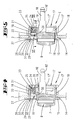
- eine Ansicht eines ohne Schlossdeckel dargestellten Einsteckschlosses mit in eine Stulpöffnung eingesetztem, eine Rollenfalle aufweisenden Einsatzteil;
- Fig. 2
- die klappfigürliche Seitenansicht zu
Fig. 1 ; - Fig. 3
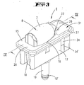
- eine perspektivische Einzelansicht des Einsatzteiles;
- Fig. 4
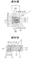
- den Schnitt gemäß der Linie IV-IV in
Fig. 3 , wobei hier die Falle ihre maximale anschlagbegrenzte Vortrittsstellung aufweist; - Fig. 5
- eine Schnittdarstellung gemäß der Darstellung in
Fig. 4 , wobei hier jedoch die Falle über einen Spindeltrieb gehäuseeinwärts verlagert wurde; - Fig. 6
- den Schnitt gemäß der Linie VI-VI in
Fig. 5 und - Fig. 7
- den Schnitt gemäß der Linie VII-VII in
Fig. 6 . - Ein in
Fig. 1 dargestelltes Schloss S kann grundsätzlich den Aufbau haben wie das in derDE 29 905 748.8 beschriebene Schloss. Basis dieses als Einsteckschlo ss ausgebildeten Schlosses S ist ein Gehäuse 1, an welchem in bekannter Weise ein Stulp 2 befestigt ist. In dem Gehäuse 1 ist in bekannter Weise ein Schließzylinder 3 angeordnet, über welchem mittels Schlüsselbetätigung ein Untersetzungsgetriebe U ansteuerbar ist. Letzteres kämmt mit eine Verzahnung aufweisenden Treibstangen 4, welche bei Schlüsselbetätigung in bekannter Weise vertikal verfahrbar sind. Im Zuge dessen ist über das Untersetzungsgetriebe U ein quer zu den Treibstangen 4 ausgerichteter Sperriegel 5 in bekannter Weise horizontal verlagerbar. Des weiteren wirkt der Schließzylinder 3 bei der Schlüsselbetätigung in bekannter Weise mit einem Wechsel 6 zusammen, welcher darüber hinaus mit einer einen Fallenkopf 7 aufweisenden Falle 8 zusammenwirkt und diese im Zuge der Schlüsselbetätigung aus ihrer Vortrittsstellung gehäuseeinwärts verlagert. - Unterhalb der Falle 8 und oberhalb des Untersetzungsgetriebes U angeordnet, lagert in dem Gehäuse 1 eine mit der Falle 8 zusammenwirkende Drückernuss 9, die ihrerseits bei einer Schwenkbewegung im Uhrzeigersinn die Falle 8 mit einem Arm aus ihrer Vortrittsstellung gehäuseeinwärts verlagert.
- Hierbei wirken sowohl der Wechsel 6 wie auch der Arm der Drückernuss 9 mit einem in dem Gehäuse 1 quer verlagerbaren und einen Fallenschwanz 10 der Falle 8 aufnehmenden Angriffsglied 11 zusammen. Letzteres wird in bekannter Weise von einer in dem Gehäuse 1 angeordneten Fallenfeder 12 federkraftbeaufschlagt, wodurch über den Fallenschwanz 10 die Falle 8 in ihrer Vortrittsstellung gehalten wird. Des weiteren ist das Angriffsglied 11 Träger eines nicht dargestellten Kupplungselements, mittels welchem die Falle 8 über den Fallenschwanz 10 mit dem Angriffsglied 11 lösbar gekuppelt ist. Hierzu besitzt der Fallenschwanz 10 an seinem Ende eine das Kupplungselement aufnehmende Ringnut 10'. Das dem Angriffsglied 11 einverleibte nicht dargestellte Kupplungselement wirkt mit einer als Hebelarm ausgestalteten und von der Gehäusewandung ausschwenkbaren Handhabe 13 zusammen.
- In diesem Ausführungsbeispiel ist die eine Stulpöffnung 14 der Stulpe 2 des Schlosses S durchsetzende Falle 8 als eine Rollenfalle ausgebildet. Ein derartiges, eine Rollenfalle 8 aufweisendes Schloss S ist üblicherweise an einer nicht dargestellten Tür ggf. auch Pendeltür oder dergleichen in bekannter Weise angeordnet.
- Damit die gegenüber der genormten Stulpöffnung 14 in ihrer Höhenerstrekkung geringer bemessene, die Rollenfalle ausbildende Falle 8 innerhalb der Stulpöffnung 14 ordnungsgemäß geführt wird, ist ein aus einem Kunststoffmaterial gefertigtes und einen Adapter ausbildendes Einsatzteil E vorgesehen. Dieses weist einen gegenüber der Grundkontur der Stulpöffnung 14 größer bemessenen Kragen 15 mit rechteckig ausgestaltetem Grundriss auf. Hierbei liegt der, eine Fallenaussparung 16 aufweisende Kragen 15 mit seiner dem Stulp 2 zugewandten Unterseite und die Stulpöffnung 14 überdeckend auf dem Stulp 2 auf. Darüber hinaus weist das Einsatzteil E an seinem Kragen 15 einen die Stulpöffnung 14 durchsetzenden und an der Unterseite des Kragens 15 angeformten, etwa topfförmig ausgestalteten etwa quaderförmigen Abschnitt 17 auf, welcher seinerseits eine der Grundkontur der Stulpöffnung 14 angepasste und etwas geringer bemessene Außenkontur aufweist, wodurch das Einsatzteil E in der Stulpöffnung 14 formschlüssig einliegt. Um diesen Formschluss zu festigen, besitzt das Einsatzteil E an den Schmalseiten des Abschnittes 17 angeordnete und flexibel ausgestaltete Federzungen 18, über welche das Einsatzteil E in die Stulpöffnung 14 formschlüssig einklippsbar ist derart, dass die Federzungen 18 die Schmalseitenwandungen der Stulpöffnung 14 hinterfangen, um somit den Formschluss zwischen dem Einsatzteil E und dem Stulp 2 zu festigen. (Vgl. insbesondere die Darstellungen in
Fig. 4 und 5 ). Das Einklippsen des Federzungen 18 ausbildenden Abschnitts 17 des Einsatzteiles E wird durch die Ausgestaltung der Federzungen 18 positiv unterstützt derart, dass die Federzungen 18 jeweils eine konkav ausgeformte Außenkontur aufweisen, welche an die zugeordnete, konvex ausgebildete Außenkontur der Schmalseiten der Stulpöffnung 14 angepasst ist. Hierdurch ist ein exaktes Einklippsen des Einsatzteiles E in die Stulpöffnung 14 möglich. (Vgl. insbesondere die Darstellung inFig. 7 ). - Bezogen auf die Zeichnungen ist in dem vertikal ausgerichteten Einsatzteil E die Falle 8 horizontal verschieblich gelagert. Hierzu besitzt das Einsatzteil E einen den Fallenkopf 7 aufnehmenden und von dem topfförmig ausgestalteten Abschnitt 17 ausgebildeten Hohlraum 17'. Der an dem Fallenkopf 7 angeformte Fallenschwanz 8 durchsetzt eine in dem Boden des Hohlraumes 17' eingebrachte und an den Durchmesser des Fallenschwanzes 10 angepasste Durchgangsöffnung 17". Darüber hinaus weist der aus der Fallenaussparung 16 ragende und etwa tonnenförmig ausgestaltete Fallenkopf 7 einen oberhalb des Fallenschwanzes 10 winkelförmig angeformten, vertikal ausgerichteten Anschlag 19 auf. Letzterer ist ebenfalls in dem Hohlraum 17' geführt derart, dass der Hohlraum 17' eine parallel zu dem Fallenschwanz 10 ausgerichtete Führungsnut 20 ausbildet. Somit ist die Falle 8 über die den Fallenkopf 7 aufnehmende Fallenaussparung 16 sowie über die den Fallenschwanz 10 aufnehmende Durchgangsöffnung 17" und die den Anschlag 19 aufnehmende Führungsnut 20 in dem Einsatzteil E horizontal verschieblich und drehfest gelagert.
- Die randoffene Führungsnut 20 des Hohlraumes 17' mündet in eine, parallel zu der Falle 8 ausgerichtete Spindellageraussparung 21, in welche eine mit einer Spindelmutter 22 zusammenwirkende Schraubenspindel 23 angeordnet ist. Zwecks drehbeweglicher Lagerung der Schraubenspindel 23 ist vorgesehen, dass diese einen gegenüber dem Schaftdurchmesser durchmesserreduzierten Lagerfortsatz 24 aufweist, welcher seinerseits in eine äquivalent ausgestaltete Lageröffnung des Bodens der Spindellageraussparung 21 einliegt. Der von dem Lagerfortsatz 24 abgewandte Schraubenspindelkopf 26 schließt bündig die Öffnung der Spindellageraussparung 21 ab. Hierbei mündet die Öffnung der Spindellageraussparung 21 in eine stufenförmig ausgestaltete Aufnahme 27. Letztere ist aus der dem Stulp abgewandten Breitseitenfläche 28 des Kragens 15 ausgeformt.
- Bezogen auf die Darstellungen in
Fig. 4 und 5 ist die einen Gegenanschlag 29 ausbildende Spindelmutter 22 derart angeordnet, dass selbige zwischen dem Anschlag 19 des Fallenkopfes 7 und dem Schraubenkopf 26 der Schraubenspindel 23 in der Aussparung 21 axial verschieblich auf der Schraubenspindel 23 gefesselt ist. Damit die den Gegenanschlag 29 ausbildende Spindelmutter 22 in der Spindellageraussparung 21 gegenüber der Schraubenspindel 23 drehfest aber dennoch von der Schraubenspindel 23 axial verlagerbar ist, ist vorgesehen, dass die etwa plattenförmig ausgestaltete Spindelmutter 22 eine radial abragende und dem Fallenkopf 7 zugewandte Nase 30 aufweist. Letztere ist, wie inFig. 7 dargestellt, mit ihrem Breitseitenflächenmaß an das lichte Maß der Führungsnut 20 angepasst. - Um diese innerhalb des Einsatzteiles E angeordnete Schraubverbindung axial zu sichern, ist ein Abdeckteil 31 vorgesehen. Dieses besitzt eine U-förmige Gestalt und ist in einer Aufnahme 27 des Einsatzteiles E formschlüssig einsetzbar, wobei das Abdeckteil 31 bündig mit der Breitseitenfläche 28 des den Kragen 15 aufweisenden Einsatzteils E abschließt. Hierbei bildet der U-Steg des Abdeckteiles 31 eine mit einer Werkzeugdurchtrittsöffnung 32 versehene Platte 33 aus. An letzterer sind die beiden U-Schenkel 34 angeformt, die in Fenstern 34' des Einsatzteil-Abschnittes 17 einrasten. Hierbei ist die Breite u des Abdeckteiles 31 konform mit der Breite des Abschnittes 17 sowie der Breite der Stulpöffnung 14. Die Länge v des Abdeckteiles 31 ist so bemessen, dass die Breitseitenfläche der Platte 33 fluchtend mit der Breitseitenfläche des Kragens 15 und die Spitzen der U-Schenkel 34 bündig mit der Breitseitenfläche des den Boden aufweisenden Abschnitts 17 abschließen. Darüber hinaus weisen jeweils die U-Schenkel 34 endseitig angeordnete und widerhakenartig ausgestaltete Rasthaken 35 auf, welche etwa stufenförmig ausgestaltete Gegenraststufen 36 des Einsatzteiles E im Bereich der Fenster 34' hintergreifen. Diese Verrastung bewirkt die axiale Fesselung der mit der Spindelmutter 22 zusammenwirkenden Schraubenspindel 23. (Vgl. insbesondere die Darstellung in
Fig. 6 ). - Um das Einsatzspektrum des eingangs erwähnten und aus dem Stand der Technik bekannten Schloss S zu erweitern, ist das eine Falle 8 aufweisende Einsatzteil E vorgesehen. Hierbei ist es nicht von Bedeutung, dass das Schloss S ggf. mit einer nicht dargestellten genormten Keilfalle schon vormontiert ist bzw. dass das Schloss S grundsätzlich einen fallenlosen Zustand aufweist. Die entsprechende Ausgestaltung des Schlo sses S sieht vor, dass in beiden Fällen in einfachster Weise das gattungsgemäße Schloss S mit dem eine Falle 8 aufweisenden Einsatzteil E in kürzester Zeit bestück- bzw. umrüstbar ist. Ist bspw. das Schloss S mit einer nicht dargestellten genormten Keilfalle ausgestattet und eine Festlegung des Schlosses S an einer Tür oder dergleichen erwünscht, muss das Schloss S in üblicher Weise eine Rollenfalle aufweisen. Um dies mit dem ein und demselben Schloss S zu realisieren, ist das eine Rollenfalle aufweisende Einsatzteil E vorgesehen. Damit die nicht dargestellte Keilfalle aus dem Schloss S entnommen werden kann, ist zunächst die an der Rückwand des Gehäuses 1 schwenkbar angeordnete Handhabe 13 gehäuseabgewandt zu verschwenken. Hierdurch wird ein mit dem Fallenschwanz 10 der Keilfalle zusammenwirkendes nicht dargestelltes Kupplungselement außer Eingriff gebracht, wodurch die aus der Stulpöffnung 14 hervorstehende Keilfalle aus dem Schloss bzw. von der Schlossmechanik entnehmbar ist. Die so freiliegende Stulpöffnung 14 des Schlosses S ist jetzt für die Aufnahme des Einsatzteiles E vorbereitet. Nun kann der Fallenschwanz 10 der als Rollenfalle ausgebildeten Falle 8 des Einsatzteiles E die Stulpöffnung 14 durchsetzend mit der Schlossmechanik bzw. mit dem nicht dargestellten Kupplungselement gekuppelt werden, um einen Formschluss mit dem durch die Fallenfeder 12 federkraftbelastete Angriffsglied 11 einzugehen. Ist dies vollzogen, nimmt die federkraftbelastete Handhabe 13 ihre Ausgangsposition ein. Einhergehend ist das Einsatzteil E über die Federzungen 18 in die Stulpöffnung 14 eingesetzt bzw. eingeklippst derart, dass die Federzungen 18 im Zuge des Einsetzens in die Stulpöffnung 14 geringfügig von den Schmalseitenwandungen der Stulpöffnung 14 aufeinander zugewandt zusammengedrückt werden. Ist der Abschnitt 17 des Einsatzteiles E in die Stulpöffnung 14 eingesetzt, so dass der Kragen 15 flächig auf dem Stulp 2 aufliegt, stellen sich die komprimierten Federzungen 18 zurück derart, dass sie die Schmalseitenwandungen der Stulpöffnung 14 hintergreifen, wodurch somit das Einsatzteil E an dem Stulp 2 festgelegt ist. Hierbei dient das Einsatzteil E praktisch als Adapter für die geringer dimensionierte als Rollenfalle ausgebildete Falle 8.
- Die Problematik besteht darin, dass ggf. eine Korrektur der mit einem nicht dargestellten Schließblech zusammenwirkenden Fallenvortrittsstellung vorgenommen werden muss. Hierzu ist mittels eines Werkzeuges bspw. eines Schraubendrehers der Schraubenkopf 26 über die Werkzeugdurchtrittsöffnung 32 des Abdeckteiles 31 drehbar, wozu ein eingesteckter Schraubendreher, bezogen auf die Darstellungen, in Uhrzeigerrichtung gedreht wird, was einhergehend die mit der Schraubenspindel 23 zusammenwirkende Spindelmutter 22 veranlasst axial gehäuseeinwärts zu wandern. Im Zuge dessen schleppt der Gegenanschlag 29 der Spindelmutter 22 den Anschlag 19 des Fallenkopfes 7 gegen die Federkraft der Fallenfeder 12 mit. Erfolgt über den nicht dargestellten Schraubendreher eine Drehung des Schraubenkopfes 26 gegen Uhrzeigerrichtung, verlagert sich der Gegenanschlag 29 der Spindelmutter 22 gehäuseauswärts. Hierbei schleppt der Anschlag 19 des Fallenkopfes 7, unterstützt durch die Fallenfeder 12, den Gegenanschlag 29 mit. Hierdurch ist die Möglichkeit gegeben, über die mit der Schraubenspindel 23 zusammenwirkenden Spindelmutter Einfluss auf die Fallenvortrittsstellung der als Rollenfalle ausgebildeten Falle 8 zu nehmen, um ggf. die Eintauchtiefe des Rollenkörpers in ein nicht dargestelltes Schließblech zu korrigieren. Auch ein nachträgliches Einstellen der Fallenvortrittsstellung ist so möglich, was insbesondere bei einer stark frequentierten Pendeltür oder dergleichen zuweilen notwendig ist.
Claims (9)
- Falle (8), insbesondere Rollenfalle, mit einem Fallenkopf (7) und einem Fallenschwanz (10),
wobei der Fallenschwanz (10) lösbar in einem Schloss (S) befestigbar ist,
wobei die Falle (8) einen die Fallenvortrittsstellung bestimmenden Anschlag (19) aufweist, der mit einem Gegenanschlag (29) zusammenwirkt, mit einem in eine Stulpöffnung (14) eines Stulps (2) einsetzbaren Einsatzteil (E), in welchem der Fallenkopf (7) geführt wird und welches den Gegenanschlag (29) ausbildet,
dadurch gekennzeichnet, dass das aus Kunststoff bestehende Einsatzteil (E) einen Kragen (15) aufweist und derart in die Stulpöffnung (14) einklippsbar ist,
dass der Kragen (15) mit seiner dem Stulp (2) zugewandten Unterseite die Stulpöffnung (14) überdeckend auf dem Stulp (2) aufliegt, wobei ein an dem Kragen (15) angeformter Abschnitt (17) die Stulpöffnung (14) durchsetzt und
wobei flexible Federzungen (18) vorgesehen sind, über welche das Einsatzteil (E) in die Stulpöffnung (14) formschlüssig einklippsbar ist. - Falle nach Anspruch 1, dadurch gekennzeichnet, dass im montierten Zustand die Federzungen (18) die Schmalseitenwandungen der Stulpöffnung (14) hintergreifen.
- Falle nach Anspruch 1 oder 2, dadurch gekennzeichnet, dass die Falle (8) eine Rollenfalle ist.
- Falle nach einem der Ansprüche 1 bis 3, dadurch gekennzeichnet, dass der Anschlag (19) ein fest mit dem Fallenkopf (7) verbundener Vorsprung ist und der Gegenanschlag (29) von einer, auf einer stulpseitig zugänglichen Schraubenspindel (23) sitzenden, gegenüber dem Einsatzteil (E) drehfesten Spindelmutter (22) gebildet ist und tiefenverstellbar ist.
- Falle nach Anspruch 4, dadurch gekennzeichnet, dass das eine Lagerende der Spindel (23) im Boden einer Spindellageraussparung (21) des Einsatzteiles (E) gelagert ist und ein Spindelkopf (26) von einem in die Spindellageraussparung (21) einsetzbaren Abdeckteil (31) überfangen ist.
- Falle nach Anspruch 5, dadurch gekennzeichnet, dass das Abdeckteil (31) eine U-Form aufweist, wobei die Enden der beiden U-Schenkel (34) des Abdeckteils (31) endseitig Rasthaken (35) aufweisen, die mit zugehörigen Gegenraststufen (36) des Einsatzteiles (E) zusammenwirken.
- Falle nach Anspruch 6, dadurch gekennzeichnet, dass die U-Schenkel (34) in Fenstern (34') des Einsatzteiles (E) einliegen.
- Falle nach einem der Ansprüche 6 bis 7, dadurch gekennzeichnet, dass der U-Steg des U-förmigen Abdeckteils (31) eine mit einer Werkzeugdurchtrittsöffnung (32) versehene Platte (33) ausbildet, welche oberflächenbündig die Spindellageraussparung (21) verschließt.
- Schloss (S) mit einer aus einer Stulpöffnung (14) vorragenden austauschbaren Falle (8), insbesondere einer Rollenfalle, mit einem Fallenkopf (7) und einem Fallenschwanz (10), wobei der Fallenschwanz (10) lösbar in dem Schloss (S) befestigt ist, um die Falle (8) zumindest teilweise aus der Stulpöffnung (14) des Schlosses (S) herauszunehmen, wobei die Falle (8) einen die Fallenvortrittsstellung bestimmenden Anschlag (19) aufweist, der mit einem Gegenanschlag (29) zusammenwirkt, mit einem in die Stulpöffnung (14) des Stulps (2) einsetzbaren Einsatzteil (E), in welchem der Fallenkopf (7) geführt wird und welches den Gegenanschlag (29) ausbildet, dadurch gekennzeichnet, dass das aus Kunststoff bestehende Einsatzteil (E) einen Kragen (15) aufweist und derart in die Stulpöffnung einklippsbar ist, dass der Kragen mit seiner dem Stulp zugewandten Unterseite die Stulpöffnung (14) überdeckend auf dem Stulp aufliegt, wobei ein an dem Kragen (15) angeformter Abschnitt (17) die Stulpöffnung (14) durchsetzt.
Applications Claiming Priority (2)
| Application Number | Priority Date | Filing Date | Title |
|---|---|---|---|
| DE10347151A DE10347151A1 (de) | 2003-10-10 | 2003-10-10 | Falle, insbesondere Rollenfalle |
| DE10347151 | 2003-10-10 |
Publications (3)
| Publication Number | Publication Date |
|---|---|
| EP1522660A2 EP1522660A2 (de) | 2005-04-13 |
| EP1522660A3 EP1522660A3 (de) | 2006-02-08 |
| EP1522660B1 true EP1522660B1 (de) | 2009-07-29 |
Family
ID=34306357
Family Applications (1)
| Application Number | Title | Priority Date | Filing Date |
|---|---|---|---|
| EP04104532A Expired - Lifetime EP1522660B1 (de) | 2003-10-10 | 2004-09-20 | Falle, insbesondere Rollenfalle sowie Schloss mit einer derartigen Falle |
Country Status (3)
| Country | Link |
|---|---|
| EP (1) | EP1522660B1 (de) |
| AT (1) | ATE438010T1 (de) |
| DE (2) | DE10347151A1 (de) |
Cited By (1)
| Publication number | Priority date | Publication date | Assignee | Title |
|---|---|---|---|---|
| CN102667032A (zh) * | 2009-10-08 | 2012-09-12 | 伊瑟欧赛拉迪有限公司 | 带有平移锁舌的多点锁 |
Families Citing this family (2)
| Publication number | Priority date | Publication date | Assignee | Title |
|---|---|---|---|---|
| DE102007043990A1 (de) * | 2007-09-14 | 2009-03-19 | Dorma Gmbh + Co. Kg | Schnappschloss |
| WO2012011134A1 (en) * | 2010-07-21 | 2012-01-26 | Cisa S.P.A. | Variable use lock |
Family Cites Families (6)
| Publication number | Priority date | Publication date | Assignee | Title |
|---|---|---|---|---|
| BE636622A (de) * | ||||
| US3197247A (en) * | 1963-02-06 | 1965-07-27 | Fred J Russell | Low friction latch bolt guide |
| CH531118A (de) * | 1969-10-08 | 1972-11-30 | Straessler Hans | Türschloss |
| US4876866A (en) * | 1986-01-31 | 1989-10-31 | W & F Manufacturing, Inc. | Door latch and deadbolt assembly |
| DE4218733A1 (de) * | 1992-06-06 | 1993-12-09 | Fuhr Carl Gmbh & Co | Falle, insbesondere an Treibstangenbeschlägen |
| AT405551B (de) * | 1996-01-19 | 1999-09-27 | Roto Frank Eisenwaren | Rollfalle mit einem rollfallenschaft |
-
2003
- 2003-10-10 DE DE10347151A patent/DE10347151A1/de not_active Withdrawn
-
2004
- 2004-09-20 AT AT04104532T patent/ATE438010T1/de active
- 2004-09-20 EP EP04104532A patent/EP1522660B1/de not_active Expired - Lifetime
- 2004-09-20 DE DE502004009812T patent/DE502004009812D1/de not_active Expired - Lifetime
Cited By (2)
| Publication number | Priority date | Publication date | Assignee | Title |
|---|---|---|---|---|
| CN102667032A (zh) * | 2009-10-08 | 2012-09-12 | 伊瑟欧赛拉迪有限公司 | 带有平移锁舌的多点锁 |
| CN102667032B (zh) * | 2009-10-08 | 2015-03-25 | 伊瑟欧赛拉迪有限公司 | 带有平移锁舌的多点锁 |
Also Published As
| Publication number | Publication date |
|---|---|
| DE502004009812D1 (de) | 2009-09-10 |
| EP1522660A2 (de) | 2005-04-13 |
| ATE438010T1 (de) | 2009-08-15 |
| DE10347151A1 (de) | 2005-05-04 |
| EP1522660A3 (de) | 2006-02-08 |
Similar Documents
| Publication | Publication Date | Title |
|---|---|---|
| DE69808030T2 (de) | Treibstangenschloss für eine Tür, Fenstertür oder dergleichen | |
| DE102013104078B4 (de) | Riegelschloss eines Möbels | |
| EP0294630B1 (de) | Verriegelungsbeschlag für Fenster, Türen od.dgl. | |
| DE29701070U1 (de) | Schloß mit Falle für Tür oder Fenster | |
| EP1522660B1 (de) | Falle, insbesondere Rollenfalle sowie Schloss mit einer derartigen Falle | |
| EP0485767A1 (de) | Verschluss für den Flügel, insbesondere Schiebeflügel eines Fensters, einer Tür od.dgl. | |
| EP2143860B1 (de) | Verschluss für Fenster oder Türen | |
| DE69900006T2 (de) | Verriegelungsbeschlag für Tür, Fenstertür oder dergleichen | |
| EP2304148B1 (de) | Bandsystem | |
| DE102008021047B4 (de) | Beschlag für ein Fenster, eine Tür oder dergleichen sowie Fenster, Tür oder dergleichen mit einem Beschlag und Verfahren zum Verriegeln und Kipplagern einer Flügelecke eines Flügels | |
| EP0128372B1 (de) | Vorrichtung zum Verriegeln des Nebenflügels eines zweiflügeligen Fensters, einer Tür od. dgl. | |
| EP1144780B1 (de) | Rotoranordnung für ein beschlagsystem | |
| EP3018269B1 (de) | Griffanordnung für ein fenster oder dergleichen sowie fenster oder dergleichen mit griffanordnung | |
| DE4228327A1 (de) | Verriegelungsbeschlag | |
| EP2025843B1 (de) | Fenster der Tür und Bauteilsatz eines Riegelteils für ein Fenster oder eine Tür | |
| DE29800926U1 (de) | Verschluß für Türen, Fenster o.dgl. | |
| DE3307563A1 (de) | Stulpschienen-treibstangenbaueinheit | |
| EP3118401A1 (de) | Kantriegel | |
| DE19507481C1 (de) | Abschließbarer Fenstergriff | |
| DE4236431C2 (de) | Verriegelungsbeschlag für Fenster oder Türen | |
| DE10200113B4 (de) | Türschloss | |
| DE2729394A1 (de) | Verriegelungseinrichtung fuer fenster, tueren o.dgl. | |
| DE29800735U1 (de) | Betätigungshandhabe | |
| DE37562C (de) | Befestigung von Thürdrückern mit verstellbarer Stiftlänge | |
| EP1361327B1 (de) | Beschlag |
Legal Events
| Date | Code | Title | Description |
|---|---|---|---|
| PUAI | Public reference made under article 153(3) epc to a published international application that has entered the european phase |
Free format text: ORIGINAL CODE: 0009012 |
|
| AK | Designated contracting states |
Kind code of ref document: A2 Designated state(s): AT BE BG CH CY CZ DE DK EE ES FI FR GB GR HU IE IT LI LU MC NL PL PT RO SE SI SK TR |
|
| AX | Request for extension of the european patent |
Extension state: AL HR LT LV MK |
|
| PUAL | Search report despatched |
Free format text: ORIGINAL CODE: 0009013 |
|
| AK | Designated contracting states |
Kind code of ref document: A3 Designated state(s): AT BE BG CH CY CZ DE DK EE ES FI FR GB GR HU IE IT LI LU MC NL PL PT RO SE SI SK TR |
|
| AX | Request for extension of the european patent |
Extension state: AL HR LT LV MK |
|
| 17P | Request for examination filed |
Effective date: 20060721 |
|
| AKX | Designation fees paid |
Designated state(s): AT BE BG CH CY CZ DE DK EE ES FI FR GB GR HU IE IT LI LU MC NL PL PT RO SE SI SK TR |
|
| 17Q | First examination report despatched |
Effective date: 20070206 |
|
| RTI1 | Title (correction) |
Free format text: LATCH BOLT, IN PARTICULAR ROLLER LATCH BOLT AND LOCK WITH SUCH A LATCH BOLT |
|
| GRAP | Despatch of communication of intention to grant a patent |
Free format text: ORIGINAL CODE: EPIDOSNIGR1 |
|
| RAP1 | Party data changed (applicant data changed or rights of an application transferred) |
Owner name: KFV KARL FLIETHER GMBH & CO. KG |
|
| GRAS | Grant fee paid |
Free format text: ORIGINAL CODE: EPIDOSNIGR3 |
|
| GRAA | (expected) grant |
Free format text: ORIGINAL CODE: 0009210 |
|
| AK | Designated contracting states |
Kind code of ref document: B1 Designated state(s): AT BE BG CH CY CZ DE DK EE ES FI FR GB GR HU IE IT LI LU MC NL PL PT RO SE SI SK TR |
|
| REG | Reference to a national code |
Ref country code: GB Ref legal event code: FG4D Free format text: NOT ENGLISH |
|
| REG | Reference to a national code |
Ref country code: CH Ref legal event code: EP |
|
| REG | Reference to a national code |
Ref country code: IE Ref legal event code: FG4D |
|
| REF | Corresponds to: |
Ref document number: 502004009812 Country of ref document: DE Date of ref document: 20090910 Kind code of ref document: P |
|
| PG25 | Lapsed in a contracting state [announced via postgrant information from national office to epo] |
Ref country code: SE Free format text: LAPSE BECAUSE OF FAILURE TO SUBMIT A TRANSLATION OF THE DESCRIPTION OR TO PAY THE FEE WITHIN THE PRESCRIBED TIME-LIMIT Effective date: 20090729 Ref country code: ES Free format text: LAPSE BECAUSE OF FAILURE TO SUBMIT A TRANSLATION OF THE DESCRIPTION OR TO PAY THE FEE WITHIN THE PRESCRIBED TIME-LIMIT Effective date: 20091109 Ref country code: FI Free format text: LAPSE BECAUSE OF FAILURE TO SUBMIT A TRANSLATION OF THE DESCRIPTION OR TO PAY THE FEE WITHIN THE PRESCRIBED TIME-LIMIT Effective date: 20090729 |
|
| PG25 | Lapsed in a contracting state [announced via postgrant information from national office to epo] |
Ref country code: SI Free format text: LAPSE BECAUSE OF FAILURE TO SUBMIT A TRANSLATION OF THE DESCRIPTION OR TO PAY THE FEE WITHIN THE PRESCRIBED TIME-LIMIT Effective date: 20090729 Ref country code: PL Free format text: LAPSE BECAUSE OF FAILURE TO SUBMIT A TRANSLATION OF THE DESCRIPTION OR TO PAY THE FEE WITHIN THE PRESCRIBED TIME-LIMIT Effective date: 20090729 |
|
| REG | Reference to a national code |
Ref country code: IE Ref legal event code: FD4D |
|
| PG25 | Lapsed in a contracting state [announced via postgrant information from national office to epo] |
Ref country code: BG Free format text: LAPSE BECAUSE OF FAILURE TO SUBMIT A TRANSLATION OF THE DESCRIPTION OR TO PAY THE FEE WITHIN THE PRESCRIBED TIME-LIMIT Effective date: 20091029 Ref country code: PT Free format text: LAPSE BECAUSE OF FAILURE TO SUBMIT A TRANSLATION OF THE DESCRIPTION OR TO PAY THE FEE WITHIN THE PRESCRIBED TIME-LIMIT Effective date: 20091129 |
|
| PG25 | Lapsed in a contracting state [announced via postgrant information from national office to epo] |
Ref country code: RO Free format text: LAPSE BECAUSE OF FAILURE TO SUBMIT A TRANSLATION OF THE DESCRIPTION OR TO PAY THE FEE WITHIN THE PRESCRIBED TIME-LIMIT Effective date: 20090729 Ref country code: DK Free format text: LAPSE BECAUSE OF FAILURE TO SUBMIT A TRANSLATION OF THE DESCRIPTION OR TO PAY THE FEE WITHIN THE PRESCRIBED TIME-LIMIT Effective date: 20090729 Ref country code: IE Free format text: LAPSE BECAUSE OF FAILURE TO SUBMIT A TRANSLATION OF THE DESCRIPTION OR TO PAY THE FEE WITHIN THE PRESCRIBED TIME-LIMIT Effective date: 20090729 Ref country code: MC Free format text: LAPSE BECAUSE OF NON-PAYMENT OF DUE FEES Effective date: 20090930 Ref country code: CZ Free format text: LAPSE BECAUSE OF FAILURE TO SUBMIT A TRANSLATION OF THE DESCRIPTION OR TO PAY THE FEE WITHIN THE PRESCRIBED TIME-LIMIT Effective date: 20090729 Ref country code: EE Free format text: LAPSE BECAUSE OF FAILURE TO SUBMIT A TRANSLATION OF THE DESCRIPTION OR TO PAY THE FEE WITHIN THE PRESCRIBED TIME-LIMIT Effective date: 20090729 |
|
| REG | Reference to a national code |
Ref country code: CH Ref legal event code: PL |
|
| PG25 | Lapsed in a contracting state [announced via postgrant information from national office to epo] |
Ref country code: SK Free format text: LAPSE BECAUSE OF FAILURE TO SUBMIT A TRANSLATION OF THE DESCRIPTION OR TO PAY THE FEE WITHIN THE PRESCRIBED TIME-LIMIT Effective date: 20090729 |
|
| PLBE | No opposition filed within time limit |
Free format text: ORIGINAL CODE: 0009261 |
|
| STAA | Information on the status of an ep patent application or granted ep patent |
Free format text: STATUS: NO OPPOSITION FILED WITHIN TIME LIMIT |
|
| 26N | No opposition filed |
Effective date: 20100503 |
|
| PG25 | Lapsed in a contracting state [announced via postgrant information from national office to epo] |
Ref country code: GR Free format text: LAPSE BECAUSE OF FAILURE TO SUBMIT A TRANSLATION OF THE DESCRIPTION OR TO PAY THE FEE WITHIN THE PRESCRIBED TIME-LIMIT Effective date: 20091030 Ref country code: LI Free format text: LAPSE BECAUSE OF NON-PAYMENT OF DUE FEES Effective date: 20090930 Ref country code: CH Free format text: LAPSE BECAUSE OF NON-PAYMENT OF DUE FEES Effective date: 20090930 |
|
| PGFP | Annual fee paid to national office [announced via postgrant information from national office to epo] |
Ref country code: GB Payment date: 20100929 Year of fee payment: 7 |
|
| PG25 | Lapsed in a contracting state [announced via postgrant information from national office to epo] |
Ref country code: IT Free format text: LAPSE BECAUSE OF FAILURE TO SUBMIT A TRANSLATION OF THE DESCRIPTION OR TO PAY THE FEE WITHIN THE PRESCRIBED TIME-LIMIT Effective date: 20090729 |
|
| PG25 | Lapsed in a contracting state [announced via postgrant information from national office to epo] |
Ref country code: LU Free format text: LAPSE BECAUSE OF NON-PAYMENT OF DUE FEES Effective date: 20090920 |
|
| PG25 | Lapsed in a contracting state [announced via postgrant information from national office to epo] |
Ref country code: HU Free format text: LAPSE BECAUSE OF FAILURE TO SUBMIT A TRANSLATION OF THE DESCRIPTION OR TO PAY THE FEE WITHIN THE PRESCRIBED TIME-LIMIT Effective date: 20100130 |
|
| PG25 | Lapsed in a contracting state [announced via postgrant information from national office to epo] |
Ref country code: TR Free format text: LAPSE BECAUSE OF FAILURE TO SUBMIT A TRANSLATION OF THE DESCRIPTION OR TO PAY THE FEE WITHIN THE PRESCRIBED TIME-LIMIT Effective date: 20090729 |
|
| PG25 | Lapsed in a contracting state [announced via postgrant information from national office to epo] |
Ref country code: CY Free format text: LAPSE BECAUSE OF FAILURE TO SUBMIT A TRANSLATION OF THE DESCRIPTION OR TO PAY THE FEE WITHIN THE PRESCRIBED TIME-LIMIT Effective date: 20090729 |
|
| GBPC | Gb: european patent ceased through non-payment of renewal fee |
Effective date: 20110920 |
|
| PG25 | Lapsed in a contracting state [announced via postgrant information from national office to epo] |
Ref country code: GB Free format text: LAPSE BECAUSE OF NON-PAYMENT OF DUE FEES Effective date: 20110920 |
|
| PGFP | Annual fee paid to national office [announced via postgrant information from national office to epo] |
Ref country code: NL Payment date: 20140921 Year of fee payment: 11 |
|
| PGFP | Annual fee paid to national office [announced via postgrant information from national office to epo] |
Ref country code: BE Payment date: 20140921 Year of fee payment: 11 |
|
| REG | Reference to a national code |
Ref country code: NL Ref legal event code: MM Effective date: 20151001 |
|
| PG25 | Lapsed in a contracting state [announced via postgrant information from national office to epo] |
Ref country code: NL Free format text: LAPSE BECAUSE OF NON-PAYMENT OF DUE FEES Effective date: 20151001 |
|
| REG | Reference to a national code |
Ref country code: FR Ref legal event code: PLFP Year of fee payment: 13 |
|
| PG25 | Lapsed in a contracting state [announced via postgrant information from national office to epo] |
Ref country code: BE Free format text: LAPSE BECAUSE OF NON-PAYMENT OF DUE FEES Effective date: 20150930 |
|
| REG | Reference to a national code |
Ref country code: FR Ref legal event code: PLFP Year of fee payment: 14 |
|
| PGFP | Annual fee paid to national office [announced via postgrant information from national office to epo] |
Ref country code: FR Payment date: 20170920 Year of fee payment: 14 |
|
| PGFP | Annual fee paid to national office [announced via postgrant information from national office to epo] |
Ref country code: AT Payment date: 20170921 Year of fee payment: 14 |
|
| PGFP | Annual fee paid to national office [announced via postgrant information from national office to epo] |
Ref country code: DE Payment date: 20170928 Year of fee payment: 14 |
|
| REG | Reference to a national code |
Ref country code: DE Ref legal event code: R119 Ref document number: 502004009812 Country of ref document: DE |
|
| REG | Reference to a national code |
Ref country code: AT Ref legal event code: MM01 Ref document number: 438010 Country of ref document: AT Kind code of ref document: T Effective date: 20180920 |
|
| PG25 | Lapsed in a contracting state [announced via postgrant information from national office to epo] |
Ref country code: DE Free format text: LAPSE BECAUSE OF NON-PAYMENT OF DUE FEES Effective date: 20190402 |
|
| PG25 | Lapsed in a contracting state [announced via postgrant information from national office to epo] |
Ref country code: FR Free format text: LAPSE BECAUSE OF NON-PAYMENT OF DUE FEES Effective date: 20180930 |
|
| PG25 | Lapsed in a contracting state [announced via postgrant information from national office to epo] |
Ref country code: AT Free format text: LAPSE BECAUSE OF NON-PAYMENT OF DUE FEES Effective date: 20180920 |