EP2025843B1 - Fenster der Tür und Bauteilsatz eines Riegelteils für ein Fenster oder eine Tür - Google Patents
Fenster der Tür und Bauteilsatz eines Riegelteils für ein Fenster oder eine Tür Download PDFInfo
- Publication number
- EP2025843B1 EP2025843B1 EP08104496A EP08104496A EP2025843B1 EP 2025843 B1 EP2025843 B1 EP 2025843B1 EP 08104496 A EP08104496 A EP 08104496A EP 08104496 A EP08104496 A EP 08104496A EP 2025843 B1 EP2025843 B1 EP 2025843B1
- Authority
- EP
- European Patent Office
- Prior art keywords
- locking
- roller
- window
- main body
- leaf
- Prior art date
- Legal status (The legal status is an assumption and is not a legal conclusion. Google has not performed a legal analysis and makes no representation as to the accuracy of the status listed.)
- Active
Links
- 230000008878 coupling Effects 0.000 claims description 3
- 238000010168 coupling process Methods 0.000 claims description 3
- 238000005859 coupling reaction Methods 0.000 claims description 3
- 238000009434 installation Methods 0.000 claims description 2
- 230000000694 effects Effects 0.000 claims 1
- 230000001747 exhibiting effect Effects 0.000 claims 1
- 238000005553 drilling Methods 0.000 description 4
- 235000001674 Agaricus brunnescens Nutrition 0.000 description 3
- 230000006978 adaptation Effects 0.000 description 1
- 238000005452 bending Methods 0.000 description 1
- 230000008901 benefit Effects 0.000 description 1
- 230000005540 biological transmission Effects 0.000 description 1
- 230000008859 change Effects 0.000 description 1
- 238000004140 cleaning Methods 0.000 description 1
- 238000010276 construction Methods 0.000 description 1
- 230000003993 interaction Effects 0.000 description 1
- 238000004519 manufacturing process Methods 0.000 description 1
- 239000002184 metal Substances 0.000 description 1
Images


Classifications
-
- E—FIXED CONSTRUCTIONS
- E05—LOCKS; KEYS; WINDOW OR DOOR FITTINGS; SAFES
- E05C—BOLTS OR FASTENING DEVICES FOR WINGS, SPECIALLY FOR DOORS OR WINDOWS
- E05C9/00—Arrangements of simultaneously actuated bolts or other securing devices at well-separated positions on the same wing
- E05C9/18—Details of fastening means or of fixed retaining means for the ends of bars
- E05C9/1808—Keepers
-
- E—FIXED CONSTRUCTIONS
- E05—LOCKS; KEYS; WINDOW OR DOOR FITTINGS; SAFES
- E05D—HINGES OR SUSPENSION DEVICES FOR DOORS, WINDOWS OR WINGS
- E05D15/00—Suspension arrangements for wings
- E05D15/48—Suspension arrangements for wings allowing alternative movements
- E05D15/52—Suspension arrangements for wings allowing alternative movements for opening about a vertical as well as a horizontal axis
- E05D15/526—Safety devices
-
- E—FIXED CONSTRUCTIONS
- E05—LOCKS; KEYS; WINDOW OR DOOR FITTINGS; SAFES
- E05F—DEVICES FOR MOVING WINGS INTO OPEN OR CLOSED POSITION; CHECKS FOR WINGS; WING FITTINGS NOT OTHERWISE PROVIDED FOR, CONCERNED WITH THE FUNCTIONING OF THE WING
- E05F7/00—Accessories for wings not provided for in other groups of this subclass
- E05F7/06—Devices for taking the weight of the wing, arranged away from the hinge axis
-
- E—FIXED CONSTRUCTIONS
- E05—LOCKS; KEYS; WINDOW OR DOOR FITTINGS; SAFES
- E05Y—INDEXING SCHEME ASSOCIATED WITH SUBCLASSES E05D AND E05F, RELATING TO CONSTRUCTION ELEMENTS, ELECTRIC CONTROL, POWER SUPPLY, POWER SIGNAL OR TRANSMISSION, USER INTERFACES, MOUNTING OR COUPLING, DETAILS, ACCESSORIES, AUXILIARY OPERATIONS NOT OTHERWISE PROVIDED FOR, APPLICATION THEREOF
- E05Y2900/00—Application of doors, windows, wings or fittings thereof
- E05Y2900/10—Application of doors, windows, wings or fittings thereof for buildings or parts thereof
- E05Y2900/13—Type of wing
- E05Y2900/132—Doors
-
- E—FIXED CONSTRUCTIONS
- E05—LOCKS; KEYS; WINDOW OR DOOR FITTINGS; SAFES
- E05Y—INDEXING SCHEME ASSOCIATED WITH SUBCLASSES E05D AND E05F, RELATING TO CONSTRUCTION ELEMENTS, ELECTRIC CONTROL, POWER SUPPLY, POWER SIGNAL OR TRANSMISSION, USER INTERFACES, MOUNTING OR COUPLING, DETAILS, ACCESSORIES, AUXILIARY OPERATIONS NOT OTHERWISE PROVIDED FOR, APPLICATION THEREOF
- E05Y2900/00—Application of doors, windows, wings or fittings thereof
- E05Y2900/10—Application of doors, windows, wings or fittings thereof for buildings or parts thereof
- E05Y2900/13—Type of wing
- E05Y2900/148—Windows
Definitions
- the invention relates to a window or a door according to the preamble of claim 1.
- the invention also relates to a component set for a window or a door.
- a latch part in which a U-shaped latch plate is associated with a base body.
- the latch plate has a latch slot for engaging a via a drive rod fitting longitudinally displaceable locking element with mushroom shape.
- the locking slot is adapted to the tapered shaft and the head of the locking element so that the shaft can enter laterally into the slot, but the head is dimensioned larger than the inside width of the slot. As a result, the locking element can not be led out of the locking slot perpendicular to the folding plane.
- the body is used in addition to the adaptation to different profiles of the spar of the window or the door and the support of the locking element, the shaft of which remains spaced from the longitudinal edges of the locking slot.
- different base bodies matched to the dimensions of the profile, are coupled with identical locking plates. The coupling is done by clipping, the assembly of the latch parts is done by means of fastening screws, which penetrate both the latch plate and the base body.
- a latch member is known in which the side of a latch plate next to a ramp is attached to which a mounted on the wing role in the leading of the wing is supported on the frame.
- Bearing block and roller are used for relative alignment of the wing to the frame to a terminals of the relative to the frame, if necessary after a time lapse and wear of the hinges moved wing to achieve.
- roller casserole or wing lifter designated facilities are from the AT-PS 286820 , of the DE-PS 336544 , and the German utility model 1813011 known.
- From the FR 1012426 of the DE-GM 1978136 and the DE 29511379 U1 Embodiments are known in which the rollers are fixedly mounted on the frame.
- the invention is therefore based on the object to remedy these disadvantages.
- a universal handling of the latch part should be achieved.
- the invention provides that the base body has a receptacle for at least one roller, and the role of the wing is assigned a casserole.
- This standardization of the Riegeteils and a wing lifter is achieved in each of which a single body can be used.
- the support in the region of the latch part is advantageous since the space between the wing and the frame free space is severely limited by the latch member itself and therefore it can come especially in this area to a terminals.
- the at least one component less must be mounted because the roller casserole or the wing lifter and the closing part are combined into one component.
- roller is associated with an opening in the latch plate, which covers the receptacle at least partially, so that the role can protrude through the latch plate, without the mechanical stability of the latch plate is reduced by an extended opening area.
- the role is determined by the latch plate on the base body, since the latch plate covers the receptacle at least partially.
- the receptacle for the roll consists of a pocket which is open approximately perpendicular to the fold.
- a simple storage of the role is achieved.
- the applied through the wing load is introduced into the body and can be optimally absorbed by the closed in the loading direction pocket.
- the base body is a symmetrical shaped body relative to its longitudinal axis, the base body can be used universally.
- roller is a roller having longitudinally identical bearing journals.
- latch member has two latch slots, then there is uniform use in right and left opening windows.
- the universal handling of the latch member is particularly effected by a component set according to claim 7.
- the latch member can be used by optional use of a base body without roller and a closed latch plate as the exclusive latch part.
- the latch part contains no openings that can absorb dirt or interfere with the cleaning of the window.
- Of the Base can be equipped with an additional wing lifter by adding a roller and using a latch plate having a corresponding opening for the roller.
- the production of the base body to be adapted to the profiling of the frame can be done more cost-effectively by a higher number of pieces and there are no new tooling and handling costs due to a further base body.
- Such a component set can be used universally in that at least one latch plate is intended for engagement of a locking element causing the tilt lock.
- the base body is a symmetrical shaped body relative to the longitudinal center axis, at least the base body can be used for windows opening to the right and to the left.
- latch member is a main body with 2 and a latch plate 3.
- the locking plate 3 has two opposite locking slots 4, 5 and two holes 6, 7.
- the locking slots 4, 5 are used for engagement of locking elements, as will be shown below.
- the holes 6, 7 serve to pass through fastening screws, with which the latch part 1 can be fixed to a frame rail of a window.
- the holes 6, 7 are with Countersinks for receiving the screw head provided.
- the latch part 1 is screwed to the fold of the frame, wherein the base body 2 is adapted to the underside of a profiling of the fold.
- the base body 2 has clearances 8, 9 in the region of the locking slots 4, 5, so that a locking element entering into the locking slots 4, 5 has sufficient free space.
- a roller 11 is attached near a front edge 10 of the latch part 1.
- the roller 11 is arranged so that its circumference projects beyond an approximately parallel to the fold extending surface 12 of the latch plate 3 and also projects beyond a radius 13.
- the edge 10 of the latch part 1 is located in the opening direction of the wing, so that it is associated with an approach to the frame, when closing the wing, the wing first.
- the latch plate 3 is formed as an L-shaped plate.
- the leg 14 includes the holes 6, 7 and an opening 15. At the approximately perpendicular to the leg 14 perpendicular leg 16 is an open-edged opening 17 is attached, which serves to pass through the roller 11.
- the latch plate 3 can be produced by stamping bending from a thin metal sheet by this configuration.
- the opening 15 can be assigned to a latching device 18 of the main body 2.
- the edge 19 of the opening 15 is thereby overlapped by a detent 20, which is designed as a latching tooth and with respect to a survey 21 is elastically deformable.
- the main body 2 engages over the locking plate 3 along the front edge 10.
- a receptacle 24 for the roller 11 is provided in the main body 2. This has an approximately perpendicular to the surface 12 and thus also perpendicular to the fold of the frame aligned open pocket 25 to which two storage pockets 26, 27 connect, which are transverse to the longitudinal central axis 28 (FIG. Fig. 1 ).
- the roller 11 is formed as a roller, the coaxial identical bearing pins 29, 30 beivi that the bearing pockets 26, 27 can be assigned. While the pocket 25 corresponds in its position and dimension approximately to the opening 17, the bearing pockets 26, 27 are covered by the locking plate 3, so that the roller 11 is fixed by the locking plate 3 on the base body 2.
- the latch plate 3 with the opening 17 provides an axial fixation in that the opening 17 engages around the roller 11 fork-shaped. An axial fixation in the body is thus unnecessary.
- the base body 2 relative to its longitudinal central axis 28 is a symmetrical molded body, which can be inexpensively made of plastic.
- the loads of the blade acting on the roller 11 can be received positively on the exclusively upward, in the direction of the wing, open trough-like bearing pockets 26, 27.
- the latch part 1 can be used both with the window opening to the right and to the left.
- a latch part 1 'visible which is also composed of a base body 2 and a latch plate 3'.
- the locking plate 3 ' but without the opening 17 ( Fig. 2 ) carried out, so that in addition to the bearing pockets 26, 27 and the bag 25 is covered.
- the latch part 1 ' is designed as a latch part without the roller casserole.
- a corresponding component set for a latch part 1 with roller casserole and a latch part 1 'without roller casserole is therefore always based on a uniform base body 2, which advantageously still has a relation to its longitudinal central axis 28 (FIG. Fig. 1 ) is designed symmetrically.
- the locking plates 3, 3 ' are of identical construction with respect to the coupling elements 18, 19, 20 cooperating with the base body 2 and differ only in that the first locking plate 1 has the opening 17 for the passage of the roller 11, while a second locking plate 3' the installation space of the roller 11, so the bag 25, the base body 2 covers when no roller 11 is attached.
- the thus configured latch member 1 can be converted by use of another latch plate 3 'in an ordinary latch part 1' or vice versa. This can also be done later, without the bolt part 1 or 1 'has to be realigned to the frame itself. It can be done according to the Fig. 5 be provided that at least the locking plate 3 or 3 'for engaging a tilt locking of the window causing locking element 31 is determined.
- the locking element 31 is mounted in the embodiment on a corner drive 32, which is part of a drive rod fitting of the window.
- the tilt lock is according to the EP 0 628 691 B2 to which reference is made in full.
- a second locking element 33 is provided, which is also designed as a mushroom pin.
- the locking elements 31, 33 depart from the in the Fig. 5 illustrated opening position of the espagnolette fitting mutually in the locking slots 4, 5, wherein the locking element 31 due to the slimmer shaft allows an inclination of the wing relative to the frame. From the Fig. 5 can still be seen that on the faceplate 34 of the corner 32 a casserole 35 is mounted, which cooperates with the roller 11.
- the casserole 35 is attached to the corner drive 32 and the wing via a fastening screw, which must be installed anyway.
- the assembly therefore represents only a small overhead.
- already assembled latch parts 1 'can be converted into latch parts 1. It can also be provided that a plurality of latch parts 1 are provided on the lower horizontal frame edge.
Landscapes
- Engineering & Computer Science (AREA)
- Mechanical Engineering (AREA)
- Support Devices For Sliding Doors (AREA)
- Extensible Doors And Revolving Doors (AREA)
- Wing Frames And Configurations (AREA)
- Lock And Its Accessories (AREA)
- Window Of Vehicle (AREA)
Description
- Die Erfindung betrifft ein Fenster oder eine Tür nach dem Oberbegriff des Anspruchs 1. Zudem betrifft die Erfindung noch einen Bauteilsatz für ein Fenster oder eine Tür.
- Fenster oder Türen nach dem Oberbegriff des Anspruchs 1 sind bereits bekannt. Bei dem aus der
EP 1208281 B1 bekannten Fenster ist ein Riegelteil vorgesehen, bei dem eine U-förmige Riegelplatte einem Grundkörper zugeordnet ist. Die Riegelplatte weist einen Riegelschlitz zum Eingriff eines über einen Treibstangenbeschlag längsverschiebbaren Riegelelementes mit Pilzkopfform auf. Dabei ist der Riegelschlitz auf den verjüngten Schaft und den Kopf des Riegelelements so abgestimmt, dass der Schaft in den Schlitz seitlich eintreten kann, der Kopf aber größer bemessen ist als die lichte Weite des Schlitzes. Dadurch kann das Riegelelement nicht senkrecht zur Falzebene aus dem Riegelschlitz herausgeführt werden. - Der Grundkörper dient neben der Anpassung an verschiedene Profilierungen des Holmes des Fensters oder der Tür auch der Abstützung des Riegelelementes, dessen Schaft von den Längsrändern des Riegelschlitzes beabstandet bleibt. Zu dem erstgenannten Zweck werden verschiedene, an die Abmessungen des Profils abgestimmte Grundkörper mit gleichen Riegelplatten gekoppelt. Die Kopplung erfolgt durch Einklipsen, wobei die Montage der Riegelteile mittels Befestigungsschrauben erfolgt, welche sowohl die Riegelplatte wie auch den Grundkörper durchdringen.
- Daneben ist es auch bereits bekannt, ein Riegelteil mit zusätzlichen Funktionen zu versehen. Aus der
DE 10009288 A1 ist beispielsweise ein Riegelteil bekannt, bei dem seitlich neben einer Riegelplatte ein Auflaufbock angebracht ist, an dem sich eine an dem Flügel angebrachte Rolle beim Heranführen des Flügels an den Rahmen abstützt. Auflaufbock und Rolle dienen der Relativausrichtung von dem Flügel zum Rahmen, um ein Klemmen des gegenüber dem Rahmen gegebenenfalls nach einem Zeitablauf und Verschleiß der Scharniere verschobenen Flügels zu erreichen. Derartige auch als Rollenauflauf oder Flügelheber bezeichnete Einrichtungen sind aus derAT-PS 286820 DE-PS 336544 1813011 bekannt. Aus derFR 1012426 DE-GM 1978136 DE 29511379 U1 sind Ausführungen bekannt, bei denen die Rollen ortsfest an dem Rahmen angebracht sind. - Bei allen letztgenannten Ausführungen müssen im Gegensatz zur
DE 10009288 A1 zusätzliche Riegelteile angebracht werden. Dies führt dazu, dass neben den Riegelteilen noch zusätzliche Bestandteile der Flügelheber am Rahmen angebracht werden müssen. Dies ist insbesondere aufgrund der beengten Platzverhältnisse, insbesondere bei kleinen Flügeln nachteilig und stört auch den Eindruck des geöffneten Fensters. Zudem ist zu bedenken, dass die Entfernung des Flügelhebers von dem Riegelteil auch deshalb klein zuhalten ist, damit ein funktionsgerechtes Zusammenwirken des rahmenseitigen Riegelteils und des flügelseitigen Riegelelementes sicher gestellt ist. Das Riegelteil und das Riegelelement sind nämlich ein vom Falz des Flügels vorstehende Bauteile, die bei einem verschobenen Flügel oft zuerst an dem Rahmen anschlagen. - Der Erfindung liegt daher die Aufgabe zugrunde, diesen Nachteilen Abhilfe zu schaffen. Zudem soll eine universelle Handhabung des Riegelteils erreicht werden.
- Dazu sieht die Erfindung vor, dass der Grundkörper eine Aufnahme für zumindest eine Rolle hat, und der Rolle an dem Flügel ein Auflauf zugeordnet ist. Damit ist eine Vereinheitlichung des Riegeteils und eines Flügelhebers erreicht, bei denen jeweils ein einheitlicher Grundkörper verwendet werden kann. Zudem ist die Abstützung im Bereich des Riegelteils von Vorteil, da hier der zwischen dem Flügel und dem Rahmen befindliche Freiraum durch das Riegelteil an sich stark eingeschränkt ist und es daher besonders in diesem Bereich zu einem Klemmen kommen kann. Letztlich ist es auch von Vorteil, dass durch die Anordnung erreicht wird, das zumindest ein Bauteil weniger montiert werden muss, da der Rollenauflauf bzw. der Flügelheber und das Schließteil zu einem Bauteil vereinigt sind.
- Eine Weiterbildung sieht vor, dass der Rolle eine Öffnung in der Riegelplatte zugeordnet ist, welche die Aufnahme zumindest teilweise abdeckt, so dass die Rolle zum einen durch die Riegelplatte vorstehen kann, ohne dass die mechanische Stabilität der Riegelplatte durch einen erweiterten Öffnungsbereich reduziert wird. Zum anderen wird die Rolle durch die Riegelplatte an dem Grundkörper festgelegt, da die Riegelplatte die Aufnahme zumindest teilweise abdeckt.
- Es ist ferner vorgesehen, dass die Aufnahme für die Rolle aus einer Tasche besteht, die annähernd senkrecht zu dem Falz offen ist. Insbesondere mit den bereits vorstehend beschriebenen Maßnahmen wird eine einfache Lagerung der Rolle erreicht. Die durch den Flügel aufgebrachte Belastung wird in den Grundkörper eingeleitet und kann durch die in Belastungsrichtung geschlossene Tasche optimal aufgenommen werden.
- Dadurch, dass der Grundkörper bezogen auf seine Längsachse ein symmetrischer Formkörper ist, kann der Grundkörper universell eingesetzt werden.
- Eine einfache weil verwechslungsfreie Montage ist dadurch gegeben, dass die Rolle eine Walze ist, die in Längsrichtung weisende identische Lagerzapfen besitzt.
- Wenn das Riegelteil zwei Riegelschlitze aufweist, dann ist eine einheitliche Verwendung bei nach rechts und bei nach links öffnenden Fenstern gegeben.
- Die universelle Handhabung des Riegelteils wird insbesondere auch durch einen Bauteilsatz nach dem Anspruch 7 bewirkt. Das Riegelteil kann durch wahlweise Verwendung eines Grundkörpers ohne Rolle und einer geschlossenen Riegelplatte als ausschließliches Riegelteil verwendet werden. Dabei enthält das Riegelteil keine Öffnungen, die Verschmutzungen aufnehmen können oder bei der Reinigung des Fensters stören. Der Grundkörper kann durch Hinzufügen einer Rolle und Verwendung einer Riegelplatte, welche eine entsprechende Öffnung für die Rolle besitzt, mit einem zusätzlichen Flügelheber ausgestattet werden. Die Herstellung des an die Profilierung des Rahmens anzupassenden Grundkörpers kann durch eine höhere Stückzahl kostengünstiger erfolgen und es entstehen keine neuen Werkzeug- und Handhabungskosten durch einen weiteren Grundkörper.
- Ein solcher Bauteilsatz kann dadurch universell genutzt werden, dass zumindest eine Riegelplatte zum Eingriff eines die Kippverriegelung bewirkenden Riegelelementes bestimmt ist.
- Wenn der Grundkörper ein, bezogen auf die Längsmittelachse symmetrischer Formkörper ist, kann zumindest der Grundkörper für nach rechts und nach links öffnende Fenster verwendet werden.
- Weitere vorteilhafte Ausgestaltungen ergeben sich aus den Zeichnungen. Es zeigt:
-
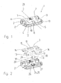
Fig. 1 ein Riegelteil mit einem Rollenauflauf, -
Fig. 2 ein Riegelteil nachFig. 1 in einer Explosionsdarstellung, -
Fig. 3 ein Riegelteil ohne Rollenauflauf, -
Fig. 4 ein Riegelteil nachFig. 3 in einer Explosionsdarstellung und -
Fig. 5 ein als Kippriegellager genutztes Riegelteil mit einer dieser zugeordneten Eckumlenkung. - Bei dem in der
Fig. 1 dargestellten Riegelteil 1 ist ein Grundkörper mit 2 und eine Riegelplatte mit 3 bezeichnet. Die Riegelplatte 3 weist zwei sich gegenüberliegende Riegelschlitze 4, 5 sowie zwei Bohrungen 6, 7 auf. Die Riegelschlitze 4, 5 dienen zum Eingriff von Riegelelementen, wie nachstehend noch dargestellt werden wird. Die Bohrungen 6, 7 dienen zum Durchtritt von Befestigungsschrauben, mit denen das Riegelteil 1 an einem Rahmenholm eines Fensters festgelegt werden kann. Die Bohrungen 6, 7 sind mit Senkungen zur Aufnahme des Schraubenkopfes versehen. Das Riegelteil 1 wird an dem Falz des Rahmens verschraubt, wobei der Grundkörper 2 unterseitig an eine Profilierung des Falzes angepasst ist. - Der Grundkörper 2 hat im Bereich der Riegelschlitze 4, 5 Freimachungen 8, 9, so dass ein in die Riegelschlitze 4, 5 eintretendes Riegelelement einen ausreichenden Freiraum hat. Nahe einer vorderen Kante 10 des Riegelteils 1 ist eine Rolle 11 angebracht. Die Rolle 11 ist so angeordnet, dass ihr Umfang über eine annähernd parallel zum Falz verlaufende Fläche 12 der Riegelplatte 3 vorsteht und auch einen Radius 13 überragt. Die Kante 10 des Riegelteils 1 liegt in Öffnungsrichtung des Flügels, so dass diese bei einer Annäherung an den Rahmen, beim Schließen des Flügels, dem Flügel zuerst zugeordnet ist.
- In Verbindung mit der
Fig. 2 wird deutlich, dass die Riegelplatte 3 als L-förmige Platte ausgebildet ist. Der Schenkel 14 beinhaltet die Bohrungen 6, 7 sowie eine Öffnung 15. An dem annähernd senkrecht zum Schenkel 14 senkrecht verlaufenden Schenkel 16 ist eine randoffene Öffnung 17 angebracht, die zum Durchtritt der Rolle 11 dient. Die Riegelplatte 3 lässt sich durch diese Ausgestaltung mittels Stanzbiegen aus einem dünnen Metallblech herstellen. - Die Öffnung 15 ist einer Rasteinrichtung 18 des Grundkörpers 2 zuordnenbar. Der Rand 19 der Öffnung 15 wird dabei von einer Rast 20 übergriffen, welche als Rastzahn ausgebildet ist und gegenüber einer Erhebung 21 elastisch verformbar ist. Gleichzeitig übergreift der Grundkörper 2 die Riegelplatte 3 entlang der vorderen Kante 10.
- Aus der
Fig. 2 wird ebenfalls deutlich, dass in dem Grundkörper 2 koaxial zu den Bohrungen 6, 7 verlaufende Bohrungen 22, 23 vorgesehen sind, durch die hindurch die Riegelplatte 3 zusammen mit dem Grundkörper 2 an dem Rahmen verschraubt werden kann. Die Rasteinrichtung 18 dient daher nur einer temporären Fixierung der Riegelplatte 3 an dem Grundkörper 2 und kann entsprechend schwach ausgebildet werden. - In dem Grundkörper 2 ist eine Aufnahme 24 für die Rolle 11 vorgesehen. Diese weist eine annähernd senkrecht zur Fläche 12 und damit auch senkrecht zu dem Falz des Rahmens ausgerichtete offene Tasche 25 auf, an die sich zwei Lagertaschen 26, 27 anschließen, die quer zu der Längsmittelachse 28 (
Fig. 1 ) verlaufen. Die Rolle 11 ist als Walze ausgeformt, die koaxiale identische Lagerzapfen 29, 30 beisitzt, die den Lagertaschen 26, 27 zuordnenbar sind. Während die Tasche 25 in ihrer Lage und Abmessung etwa der Öffnung 17 entspricht, werden die Lagertaschen 26, 27 durch die Riegelplatte 3 abgedeckt, so dass die Rolle 11 durch die Riegelplatte 3 an dem Grundkörper 2 festgelegt ist. Gleichzeitig bietet die Riegelplatte 3 mit der Öffnung 17 einen axiale Festlegung dadurch, dass die Öffnung 17 die Rolle 11 gabelförmig umgreift. Eine axiale Festlegung im Grundkörper ist damit entbehrlich. - Vorteilhaft bei alledem ist noch, dass der Grundkörper 2 bezogen auf seine Längsmittelachse 28 ein symmetrischer Formkörper ist, der kostengünstig aus Kunststoff hergestellt werden kann. Die Belastungen des auf die Rolle 11 wirkenden Flügels kann über die ausschließlich nach oben, in Richtung des Flügels, offenen muldenartige Lagertaschen 26, 27 formschlüssig aufgenommen werden.
- Um neben dem Grundkörper 2 auch die Riegelplatte 3 universell nutzen zu können ist vorgesehen, dass das Riegelteil 1 und damit die Riegelplatte 3 zwei, bezüglich der Längsmittelachse 28 symmetrisch angeordnete Riegelschlitze 4, 5, aufweist. Dadurch kann das Riegelteil 1 sowohl bei nach rechts wie auch nach links öffnenden Fensters verwendet werden.
- In der
Fig. 3 ist ein Riegelteil 1' sichtbar, welches ebenfalls aus einem Grundkörper 2 und einer Riegelplatte 3' zusammengesetzt ist. Hierbei ist die Riegelplatte 3' jedoch ohne die Öffnung 17 (Fig. 2 ) ausgeführt, so dass neben den Lagertaschen 26, 27 auch die Tasche 25 abgedeckt ist. Dadurch ist das Riegelteil 1' als Riegelteil ohne den Rollenauflauf ausgebildet. - Ein entsprechender Bauteilsatz für ein Riegelteil 1 mit Rollenauflauf und ein Riegelteil 1' ohne Rollenauflauf basiert daher immer auf einem einheitlichen Grundkörper 2, der vorteilhaft dabei noch bezogen auf seine Längsmittelachse 28 (
Fig. 1 ) symmetrisch gestaltet ist. Die Riegelplatten 3, 3' sind bezüglich der mit dem Grundkörper 2 zusammenwirkenden Kopplungsglieder 18, 19, 20 identisch ausgebildet sind und unterscheiden sich nur darin, dass die erste Riegelplatte 1 die Öffnung 17 zum Durchtritt der Rolle 11 besitzt, während eine zweite Riegelplatte 3' den Einbauraum der Rolle 11, also die Tasche 25, des Grundkörpers 2 abdeckt, wenn keine Rolle 11 angebracht ist. - Das so gestaltete Riegelteil 1 kann durch Verwendung einer anderen Riegelplatte 3' in ein gewöhnliches Riegelteil 1' gewandelt werden oder umgekehrt. Dies kann auch nachträglich erfolgen, ohne dass das Riegelteil 1 bzw. 1' an sich an dem Rahmen neu ausgerichtet werden muss. Es kann entsprechend der
Fig. 5 noch vorgesehen sein, dass zumindest die Riegelplatte 3 oder 3' zum Eingriff eines die Kippverriegelung des Fensters bewirkenden Riegelelementes 31 bestimmt ist. - Das Riegelelement 31 ist in dem Ausführungsbeispiel an einer Eckumlenkung 32 angebracht, die Teil eines Treibstangenbeschlages des Fensters ist. Die Kippverriegelung ist entsprechend der
EP 0 628 691 B2 beschaffen, auf die diesbezüglich vollinhaltlich Bezug genommen wird. Neben dem als Pilzbolzen ausgeführten Riegelelement 31 ist ein zweites Riegelelement 33 vorgesehen, welches ebenfalls als Pilzbolzen beschaffen ist. - Die Riegelelemente 31, 33 fahren ausgehend von der in der
Fig. 5 dargestellten Öffnungsstellung des Treibstangenbeschlages wechselseitig in die Riegelschlitze 4, 5 ein, wobei das Riegelelement 31 aufgrund des schlankeren Schaftes eine Neigung des Flügels gegenüber dem Rahmen zulässt. Aus derFig. 5 ist noch ersichtlich, dass an der Stulpschiene 34 der Eckumlenkung 32 ein Auflauf 35 angebracht ist, der mit der Rolle 11 zusammenwirkt. - Der Auflauf 35 wird dabei an der Eckumlenkung 32 bzw. dem Flügel über eine Befestigungsschraube befestigt, welche ohnehin angebracht werden muss. Die Montage stellt daher einen nur geringen Mehraufwand dar. Gleichzeitig kann mit der Ausgestaltung des Riegelteils 1 bzw. 1' ein Riegelteil, ein Riegelteil mit Rollenauflauf und ein Kippverriegelungsteil geschaffen werden. Dies ist im Besonderen im Hinblick auf eine zunehmende Automatisierung von Vorteil, das sich die Beuteilabmessungen nicht ändern und daher zum einen die automatischen Zuführungen der Riegelteile 1, 1' identisch ausgeführt werden können und zum anderen weniger Bauteile montiert werden müssen. Daneben können - wie bereits ausgeführt - auch bereits montierte Riegelteile 1' in Riegelteile 1 umgewandelt werden. Es kann auch vorgesehen werden, dass an der unteren horizontalen Rahmenkante mehrere Riegelteile 1 vorgesehen werden.
-
- 1, 1'
- Riegelteil
- 2
- Grundkörper
- 3, 3'
- Riegelplatte
- 4
- Riegelschlitz
- 5
- Riegelschlitz
- 6
- Bohrung
- 7
- Bohrung
- 8
- Freimachung
- 9
- Freimachung
- 10
- Kante
- 11
- Rolle
- 12
- Fläche
- 13
- Radius
- 14
- Schenkel
- 15
- Öffnung
- 16
- Schenkel
- 17
- Öffnung
- 18
- Rasteinrichtung
- 19
- Rand
- 20
- Rast
- 21
- Erhebung
- 22
- Bohrung
- 23
- Bohrung
- 24
- Aufnahme
- 25
- Tasche
- 26
- Lagertasche
- 27
- Lagertasche
- 28
- Längsmittelachse
- 29
- Lagerzapfen
- 30
- Lagerzapfen
- 31
- Riegelelement
- 32
- Eckumlenkung
- 33
- Riegelelement
- 34
- Stulpschiene
- 35
- Auflauf
Claims (9)
- Fenster oder Tür mit einem im Falz zwischen Flügel und Rahmen angeordneten Riegelteil (1,1'), insbesondere Kippriegelteil und einem an dem Flügel angebrachten Treibstangenbeschlag (32) und mindestens einem über den Treibstangenbeschlag (32) bewegbaren Riegelelement (31, 33), dem an dem ortsfesten Rahmen das Riegelteil (1, 1') zugeordnet ist, wobei über den Treibstangenbeschlag (32) der Flügel zumindest aus einer Verschlussstellung in zumindest eine Öffnungsstellung bringbar ist, in der der Flügel aus dem Rahmen schwenkbar ist, wobei das Riegelteil (1, 1') aus zumindest einem Grundkörper (2) und einer daran kuppelbaren Riegelplatte (3, 3') besteht,
dadurch gekennzeichnet,
dass der Grundkörper (2) eine Aufnahme (24) für zumindest eine Rolle (11) hat, und der Rolle (11) an dem Flügel ein Auflauf (35) zuordenbar ist. - Fenster oder Tür nach Anspruch 1,
dadurch gekennzeichnet,
dass der Rolle (11) eine Öffnung (17) in der Riegelplatte (3) zugeordnet ist, welche die Aufnahme (24) zumindest teilweise abdeckt. - Fenster oder Tür nach Anspruch 1 oder 2,
dadurch gekennzeichnet,
dass die Aufnahme (24) für die Rolle (11) aus einer Tasche (25) besteht, die annähernd senkrecht zu dem Falz offen ist. - Fenster oder Tür nach einem der Ansprüche 1 bis 3,
dadurch gekennzeichnet,
dass der Grundkörper (2) bezogen auf seine Längsmittelachse (28) ein symmetrischer Formkörper ist. - Fenster oder Tür nach einem der Ansprüche 1 bis 4,
dadurch gekennzeichnet,
dass die Rolle (11) eine Walze ist, die in Längsrichtung weisende identische Lagerzapfen (29, 30) besitzt. - Fenster oder Tür nach einem der Ansprüche 1 bis 5,
dadurch gekennzeichnet,
dass das Riegelteil (1, 1') zwei Riegelschlitze (4, 5) aufweist. - Bauteilsatz für Riegelteile (1, 1'), insbesondere für ein Fenster oder eine Tür nach dem Anspruch 1, mit einem verlagerbare Riegelelemente (31, 32) aufweisenden Treibstangenbeschlag, bestehend aus einem Grundkörper (2) und zumindest zwei daran wechselseitig kuppelbaren Riegelplatten (3, 3'), wobei der Grundkörper (2) zumindest eine Aufnahme (24) für zumindest eine Rolle (11) hat, der an dem Flügel ein Auflauf (35) zugeordnet, wobei die Riegelplatten (3, 3') zumindest bezüglich der mit dem Grundkörper (2) zusammenwirkenden Kopplungsglieder (18, 19, 20) identisch ausgebildet sind und eine erste Riegelplatte (3) eine Öffnung (17) zum Durchtritt der Rolle (11) besitzt, während eine zweite Riegelplatte (3') den Einbauraum der Rolle (11) im Grundkörpers (2) abdeckt, wenn keine Rolle (11) angebracht ist.
- Bauteilsatz nach Anspruch 7,
dadurch gekennzeichnet,
dass zumindest eine Riegelplatte (3, 3') zum Eingriff eines die Kippverriegelung bewirkenden Riegelelementes (31) bestimmt ist. - Bauteilsatz nach Anspruch 7 oder 8,
dadurch gekennzeichnet,
dass der Grundkörper (2) ein bezogen auf die Längsmittelachse (28) symmetrischer Formkörper ist.
Priority Applications (1)
| Application Number | Priority Date | Filing Date | Title |
|---|---|---|---|
| PL08104496T PL2025843T3 (pl) | 2007-08-14 | 2008-06-20 | Okno lub drzwi i zestaw części rygla dla okna lub drzwi |
Applications Claiming Priority (1)
| Application Number | Priority Date | Filing Date | Title |
|---|---|---|---|
| DE202007011394U DE202007011394U1 (de) | 2007-08-14 | 2007-08-14 | Fenster oder Tür und Bauteilsatz eines Riegelteils für ein Fenster oder eine Tür |
Publications (3)
| Publication Number | Publication Date |
|---|---|
| EP2025843A2 EP2025843A2 (de) | 2009-02-18 |
| EP2025843A3 EP2025843A3 (de) | 2010-08-04 |
| EP2025843B1 true EP2025843B1 (de) | 2011-11-30 |
Family
ID=39846576
Family Applications (1)
| Application Number | Title | Priority Date | Filing Date |
|---|---|---|---|
| EP08104496A Active EP2025843B1 (de) | 2007-08-14 | 2008-06-20 | Fenster der Tür und Bauteilsatz eines Riegelteils für ein Fenster oder eine Tür |
Country Status (4)
| Country | Link |
|---|---|
| EP (1) | EP2025843B1 (de) |
| AT (1) | ATE535670T1 (de) |
| DE (1) | DE202007011394U1 (de) |
| PL (1) | PL2025843T3 (de) |
Cited By (1)
| Publication number | Priority date | Publication date | Assignee | Title |
|---|---|---|---|---|
| DE202019106095U1 (de) | 2019-11-04 | 2019-11-15 | Siegenia-Aubi Kg | Bauteilsystem für einen Riegeleingriff |
Families Citing this family (1)
| Publication number | Priority date | Publication date | Assignee | Title |
|---|---|---|---|---|
| DE102015215458B3 (de) * | 2015-08-13 | 2016-12-22 | Roto Frank Ag | Beschlagteil mit schräg zur Schließrichtung eines Fensters oder einer Tür angeordneter Walze sowie ein Fenster oder eine Tür mit einem solchen Beschlagteil |
Family Cites Families (10)
| Publication number | Priority date | Publication date | Assignee | Title |
|---|---|---|---|---|
| DE336544C (de) | 1921-05-09 | Edouard Debant | Vorrichtung zum Heben von Tueren mittels Laufrolle und Auflaufbahn | |
| FR1012426A (fr) | 1949-08-26 | 1952-07-09 | Dispositif destiné à empêcher le coincement et le frottement des battants de fenêtres, ou autres, dans leurs encadrements | |
| DE1813011U (de) | 1960-03-28 | 1960-06-09 | Hartmann & Co W | Vorrichtung zum wahlweisen drehen und kippen von metallfenstern. |
| DE1978136U (de) | 1967-07-18 | 1968-02-01 | Eugen Notter O H G | Fenster mit stockrahmen und fluegelrahmen. |
| AT286820B (de) | 1967-11-30 | 1970-12-28 | Ver Baubeschlag Gretsch Co | Einstellbare Auflaufvorrichtung zum Anheben der sich beim Öffnen senkenden Flügel von Fenstern, Türen od.dgl. in eine vorbestimmte Schließstellung |
| DE1813011A1 (de) | 1968-12-06 | 1970-07-09 | Basf Ag | Photopolymerisierbare Stoffmischungen |
| DE9308472U1 (de) | 1993-06-07 | 1993-09-02 | Pax Schweikhard Gmbh | Dreh-Kipp-Beschlag für Fenster, Türen o.dgl. |
| DE29511379U1 (de) | 1995-07-14 | 1996-11-14 | Niemann Hans Dieter | Auflaufbock |
| DE29914072U1 (de) | 1999-08-16 | 1999-11-18 | Siegenia Frank Kg | Verriegelungsbeschlag |
| DE10009288A1 (de) | 2000-02-28 | 2001-08-30 | Siegenia Frank Kg | Auflaufbock |
-
2007
- 2007-08-14 DE DE202007011394U patent/DE202007011394U1/de not_active Expired - Lifetime
-
2008
- 2008-06-20 EP EP08104496A patent/EP2025843B1/de active Active
- 2008-06-20 PL PL08104496T patent/PL2025843T3/pl unknown
- 2008-06-20 AT AT08104496T patent/ATE535670T1/de active
Cited By (2)
| Publication number | Priority date | Publication date | Assignee | Title |
|---|---|---|---|---|
| DE202019106095U1 (de) | 2019-11-04 | 2019-11-15 | Siegenia-Aubi Kg | Bauteilsystem für einen Riegeleingriff |
| EP3816375A1 (de) | 2019-11-04 | 2021-05-05 | Siegenia-Aubi Kg | Bauteilsystem für einen riegeleingriff |
Also Published As
| Publication number | Publication date |
|---|---|
| EP2025843A2 (de) | 2009-02-18 |
| ATE535670T1 (de) | 2011-12-15 |
| DE202007011394U1 (de) | 2008-12-24 |
| EP2025843A3 (de) | 2010-08-04 |
| PL2025843T3 (pl) | 2012-04-30 |
Similar Documents
| Publication | Publication Date | Title |
|---|---|---|
| EP3102759B1 (de) | Beschlag eines zumindest hebbaren und verschiebbaren flügels von fenstern oder türen | |
| EP1568833B1 (de) | Schliessblech für ein Fenster oder eine Tür | |
| EP2085553B1 (de) | Eckband eines Ecklagers | |
| EP3060737B1 (de) | Fenster oder tür mit einem beschlag | |
| EP2251508B1 (de) | Schliessblech für Fenster oder Türen | |
| EP2025843B1 (de) | Fenster der Tür und Bauteilsatz eines Riegelteils für ein Fenster oder eine Tür | |
| DE3904210C2 (de) | ||
| DE3619682C2 (de) | ||
| EP1580374B1 (de) | Fenster oder Tür | |
| WO2017093268A1 (de) | Beschlaganordnung | |
| DE10056607C1 (de) | Fehlbedienungssperre für Treibstangenbeschläge | |
| DE19911893C2 (de) | Beschlaganordnung | |
| EP2122092B1 (de) | Beschlag | |
| EP3350394B1 (de) | Treibstangenbeschlag | |
| EP1498563B1 (de) | Spaltlüftungsvorrichtung | |
| EP0246431A2 (de) | Ausstellvorrichtung für Kippflügel, insbesondere Drehkipp- oder auch Schiebekippflügel, von Fenstern, Türen od. dgl. | |
| EP1425489B1 (de) | Drehkippbeschlag | |
| DE2729394A1 (de) | Verriegelungseinrichtung fuer fenster, tueren o.dgl. | |
| DE102017202727B4 (de) | Verdeckt angeordneter Beschlag für Fenster, Türen oder dergleichen | |
| WO2006131447A1 (de) | Beschlag | |
| EP1582672B1 (de) | Eckumlenkung für feststellbare Spalt-Lüftungsöffnungen und Öffnungsbegrenzung bei einem Zentralverschluss | |
| EP2090730B1 (de) | Verriegelungsvorrichtung | |
| DE202018000955U1 (de) | Beschlagteil für ein Fenster oder eine Tür | |
| DE7713995U1 (de) | Eckumlenkung fuer einen stellstangenbeschlag eines drehkippfensters o.dgl. | |
| EP2154318A1 (de) | Fenster oder Tür mit Öffnungsbegrenzer |
Legal Events
| Date | Code | Title | Description |
|---|---|---|---|
| PUAI | Public reference made under article 153(3) epc to a published international application that has entered the european phase |
Free format text: ORIGINAL CODE: 0009012 |
|
| AK | Designated contracting states |
Kind code of ref document: A2 Designated state(s): AT BE BG CH CY CZ DE DK EE ES FI FR GB GR HR HU IE IS IT LI LT LU LV MC MT NL NO PL PT RO SE SI SK TR |
|
| AX | Request for extension of the european patent |
Extension state: AL BA MK RS |
|
| PUAL | Search report despatched |
Free format text: ORIGINAL CODE: 0009013 |
|
| AK | Designated contracting states |
Kind code of ref document: A3 Designated state(s): AT BE BG CH CY CZ DE DK EE ES FI FR GB GR HR HU IE IS IT LI LT LU LV MC MT NL NO PL PT RO SE SI SK TR |
|
| AX | Request for extension of the european patent |
Extension state: AL BA MK RS |
|
| RIC1 | Information provided on ipc code assigned before grant |
Ipc: E05F 7/06 20060101ALI20100628BHEP Ipc: E05C 9/18 20060101AFI20100628BHEP |
|
| 17P | Request for examination filed |
Effective date: 20100818 |
|
| AKX | Designation fees paid |
Designated state(s): AT BE BG CH CY CZ DE DK EE ES FI FR GB GR HR HU IE IS IT LI LT LU LV MC MT NL NO PL PT RO SE SI SK TR |
|
| REG | Reference to a national code |
Ref country code: DE Ref legal event code: R079 Ref document number: 502008005727 Country of ref document: DE Free format text: PREVIOUS MAIN CLASS: E05C0009000000 Ipc: E05C0009180000 |
|
| GRAP | Despatch of communication of intention to grant a patent |
Free format text: ORIGINAL CODE: EPIDOSNIGR1 |
|
| RIC1 | Information provided on ipc code assigned before grant |
Ipc: E05F 7/06 20060101ALI20110714BHEP Ipc: E05C 9/18 20060101AFI20110714BHEP |
|
| GRAS | Grant fee paid |
Free format text: ORIGINAL CODE: EPIDOSNIGR3 |
|
| GRAA | (expected) grant |
Free format text: ORIGINAL CODE: 0009210 |
|
| AK | Designated contracting states |
Kind code of ref document: B1 Designated state(s): AT BE BG CH CY CZ DE DK EE ES FI FR GB GR HR HU IE IS IT LI LT LU LV MC MT NL NO PL PT RO SE SI SK TR |
|
| REG | Reference to a national code |
Ref country code: GB Ref legal event code: FG4D Free format text: NOT ENGLISH Ref country code: CH Ref legal event code: EP |
|
| REG | Reference to a national code |
Ref country code: IE Ref legal event code: FG4D Free format text: LANGUAGE OF EP DOCUMENT: GERMAN |
|
| REG | Reference to a national code |
Ref country code: DE Ref legal event code: R096 Ref document number: 502008005727 Country of ref document: DE Effective date: 20120216 |
|
| REG | Reference to a national code |
Ref country code: NL Ref legal event code: VDEP Effective date: 20111130 |
|
| LTIE | Lt: invalidation of european patent or patent extension |
Effective date: 20111130 |
|
| PG25 | Lapsed in a contracting state [announced via postgrant information from national office to epo] |
Ref country code: IS Free format text: LAPSE BECAUSE OF FAILURE TO SUBMIT A TRANSLATION OF THE DESCRIPTION OR TO PAY THE FEE WITHIN THE PRESCRIBED TIME-LIMIT Effective date: 20120330 Ref country code: LT Free format text: LAPSE BECAUSE OF FAILURE TO SUBMIT A TRANSLATION OF THE DESCRIPTION OR TO PAY THE FEE WITHIN THE PRESCRIBED TIME-LIMIT Effective date: 20111130 Ref country code: NO Free format text: LAPSE BECAUSE OF FAILURE TO SUBMIT A TRANSLATION OF THE DESCRIPTION OR TO PAY THE FEE WITHIN THE PRESCRIBED TIME-LIMIT Effective date: 20120229 |
|
| REG | Reference to a national code |
Ref country code: PL Ref legal event code: T3 |
|
| PG25 | Lapsed in a contracting state [announced via postgrant information from national office to epo] |
Ref country code: HR Free format text: LAPSE BECAUSE OF FAILURE TO SUBMIT A TRANSLATION OF THE DESCRIPTION OR TO PAY THE FEE WITHIN THE PRESCRIBED TIME-LIMIT Effective date: 20111130 Ref country code: NL Free format text: LAPSE BECAUSE OF FAILURE TO SUBMIT A TRANSLATION OF THE DESCRIPTION OR TO PAY THE FEE WITHIN THE PRESCRIBED TIME-LIMIT Effective date: 20111130 Ref country code: LV Free format text: LAPSE BECAUSE OF FAILURE TO SUBMIT A TRANSLATION OF THE DESCRIPTION OR TO PAY THE FEE WITHIN THE PRESCRIBED TIME-LIMIT Effective date: 20111130 Ref country code: SI Free format text: LAPSE BECAUSE OF FAILURE TO SUBMIT A TRANSLATION OF THE DESCRIPTION OR TO PAY THE FEE WITHIN THE PRESCRIBED TIME-LIMIT Effective date: 20111130 Ref country code: SE Free format text: LAPSE BECAUSE OF FAILURE TO SUBMIT A TRANSLATION OF THE DESCRIPTION OR TO PAY THE FEE WITHIN THE PRESCRIBED TIME-LIMIT Effective date: 20111130 Ref country code: PT Free format text: LAPSE BECAUSE OF FAILURE TO SUBMIT A TRANSLATION OF THE DESCRIPTION OR TO PAY THE FEE WITHIN THE PRESCRIBED TIME-LIMIT Effective date: 20120330 |
|
| REG | Reference to a national code |
Ref country code: IE Ref legal event code: FD4D |
|
| PG25 | Lapsed in a contracting state [announced via postgrant information from national office to epo] |
Ref country code: CY Free format text: LAPSE BECAUSE OF FAILURE TO SUBMIT A TRANSLATION OF THE DESCRIPTION OR TO PAY THE FEE WITHIN THE PRESCRIBED TIME-LIMIT Effective date: 20111130 |
|
| PG25 | Lapsed in a contracting state [announced via postgrant information from national office to epo] |
Ref country code: BG Free format text: LAPSE BECAUSE OF FAILURE TO SUBMIT A TRANSLATION OF THE DESCRIPTION OR TO PAY THE FEE WITHIN THE PRESCRIBED TIME-LIMIT Effective date: 20120229 Ref country code: DK Free format text: LAPSE BECAUSE OF FAILURE TO SUBMIT A TRANSLATION OF THE DESCRIPTION OR TO PAY THE FEE WITHIN THE PRESCRIBED TIME-LIMIT Effective date: 20111130 Ref country code: EE Free format text: LAPSE BECAUSE OF FAILURE TO SUBMIT A TRANSLATION OF THE DESCRIPTION OR TO PAY THE FEE WITHIN THE PRESCRIBED TIME-LIMIT Effective date: 20111130 Ref country code: IE Free format text: LAPSE BECAUSE OF FAILURE TO SUBMIT A TRANSLATION OF THE DESCRIPTION OR TO PAY THE FEE WITHIN THE PRESCRIBED TIME-LIMIT Effective date: 20111130 Ref country code: CZ Free format text: LAPSE BECAUSE OF FAILURE TO SUBMIT A TRANSLATION OF THE DESCRIPTION OR TO PAY THE FEE WITHIN THE PRESCRIBED TIME-LIMIT Effective date: 20111130 Ref country code: SK Free format text: LAPSE BECAUSE OF FAILURE TO SUBMIT A TRANSLATION OF THE DESCRIPTION OR TO PAY THE FEE WITHIN THE PRESCRIBED TIME-LIMIT Effective date: 20111130 |
|
| PG25 | Lapsed in a contracting state [announced via postgrant information from national office to epo] |
Ref country code: RO Free format text: LAPSE BECAUSE OF FAILURE TO SUBMIT A TRANSLATION OF THE DESCRIPTION OR TO PAY THE FEE WITHIN THE PRESCRIBED TIME-LIMIT Effective date: 20111130 |
|
| PLBE | No opposition filed within time limit |
Free format text: ORIGINAL CODE: 0009261 |
|
| STAA | Information on the status of an ep patent application or granted ep patent |
Free format text: STATUS: NO OPPOSITION FILED WITHIN TIME LIMIT |
|
| 26N | No opposition filed |
Effective date: 20120831 |
|
| REG | Reference to a national code |
Ref country code: DE Ref legal event code: R097 Ref document number: 502008005727 Country of ref document: DE Effective date: 20120831 |
|
| BERE | Be: lapsed |
Owner name: SIEGENIA-AUBI K.G. Effective date: 20120630 |
|
| PG25 | Lapsed in a contracting state [announced via postgrant information from national office to epo] |
Ref country code: MC Free format text: LAPSE BECAUSE OF NON-PAYMENT OF DUE FEES Effective date: 20120630 |
|
| REG | Reference to a national code |
Ref country code: CH Ref legal event code: PL |
|
| REG | Reference to a national code |
Ref country code: CH Ref legal event code: PL |
|
| GBPC | Gb: european patent ceased through non-payment of renewal fee |
Effective date: 20120620 |
|
| REG | Reference to a national code |
Ref country code: HU Ref legal event code: AG4A Ref document number: E015003 Country of ref document: HU |
|
| PG25 | Lapsed in a contracting state [announced via postgrant information from national office to epo] |
Ref country code: CH Free format text: LAPSE BECAUSE OF NON-PAYMENT OF DUE FEES Effective date: 20120630 Ref country code: GB Free format text: LAPSE BECAUSE OF NON-PAYMENT OF DUE FEES Effective date: 20120620 Ref country code: BE Free format text: LAPSE BECAUSE OF NON-PAYMENT OF DUE FEES Effective date: 20120630 Ref country code: LI Free format text: LAPSE BECAUSE OF NON-PAYMENT OF DUE FEES Effective date: 20120630 |
|
| PG25 | Lapsed in a contracting state [announced via postgrant information from national office to epo] |
Ref country code: FI Free format text: LAPSE BECAUSE OF FAILURE TO SUBMIT A TRANSLATION OF THE DESCRIPTION OR TO PAY THE FEE WITHIN THE PRESCRIBED TIME-LIMIT Effective date: 20111130 |
|
| PG25 | Lapsed in a contracting state [announced via postgrant information from national office to epo] |
Ref country code: MT Free format text: LAPSE BECAUSE OF FAILURE TO SUBMIT A TRANSLATION OF THE DESCRIPTION OR TO PAY THE FEE WITHIN THE PRESCRIBED TIME-LIMIT Effective date: 20111130 |
|
| PG25 | Lapsed in a contracting state [announced via postgrant information from national office to epo] |
Ref country code: ES Free format text: LAPSE BECAUSE OF FAILURE TO SUBMIT A TRANSLATION OF THE DESCRIPTION OR TO PAY THE FEE WITHIN THE PRESCRIBED TIME-LIMIT Effective date: 20120311 |
|
| PG25 | Lapsed in a contracting state [announced via postgrant information from national office to epo] |
Ref country code: TR Free format text: LAPSE BECAUSE OF FAILURE TO SUBMIT A TRANSLATION OF THE DESCRIPTION OR TO PAY THE FEE WITHIN THE PRESCRIBED TIME-LIMIT Effective date: 20111130 |
|
| PG25 | Lapsed in a contracting state [announced via postgrant information from national office to epo] |
Ref country code: LU Free format text: LAPSE BECAUSE OF NON-PAYMENT OF DUE FEES Effective date: 20120620 |
|
| PG25 | Lapsed in a contracting state [announced via postgrant information from national office to epo] |
Ref country code: GR Free format text: LAPSE BECAUSE OF FAILURE TO SUBMIT A TRANSLATION OF THE DESCRIPTION OR TO PAY THE FEE WITHIN THE PRESCRIBED TIME-LIMIT Effective date: 20111130 |
|
| REG | Reference to a national code |
Ref country code: FR Ref legal event code: PLFP Year of fee payment: 9 |
|
| REG | Reference to a national code |
Ref country code: FR Ref legal event code: PLFP Year of fee payment: 10 |
|
| REG | Reference to a national code |
Ref country code: FR Ref legal event code: PLFP Year of fee payment: 11 |
|
| PGFP | Annual fee paid to national office [announced via postgrant information from national office to epo] |
Ref country code: FR Payment date: 20230623 Year of fee payment: 16 Ref country code: DE Payment date: 20230627 Year of fee payment: 16 |
|
| PGFP | Annual fee paid to national office [announced via postgrant information from national office to epo] |
Ref country code: PL Payment date: 20230525 Year of fee payment: 16 Ref country code: HU Payment date: 20230615 Year of fee payment: 16 Ref country code: AT Payment date: 20230622 Year of fee payment: 16 |
|
| PGFP | Annual fee paid to national office [announced via postgrant information from national office to epo] |
Ref country code: IT Payment date: 20230629 Year of fee payment: 16 |