EP1521258B1 - Wiedergabegerät, Betriebsvorrichtung für Wiedergabe und Wiedergabemethode dafür - Google Patents
Wiedergabegerät, Betriebsvorrichtung für Wiedergabe und Wiedergabemethode dafür Download PDFInfo
- Publication number
- EP1521258B1 EP1521258B1 EP04251505A EP04251505A EP1521258B1 EP 1521258 B1 EP1521258 B1 EP 1521258B1 EP 04251505 A EP04251505 A EP 04251505A EP 04251505 A EP04251505 A EP 04251505A EP 1521258 B1 EP1521258 B1 EP 1521258B1
- Authority
- EP
- European Patent Office
- Prior art keywords
- section
- discal unit
- rotational speed
- rotational direction
- reproducing
- Prior art date
- Legal status (The legal status is an assumption and is not a legal conclusion. Google has not performed a legal analysis and makes no representation as to the accuracy of the status listed.)
- Expired - Lifetime
Links
- 238000000034 method Methods 0.000 title claims description 10
- 230000003287 optical effect Effects 0.000 description 66
- 238000010586 diagram Methods 0.000 description 7
- 230000001965 increasing effect Effects 0.000 description 5
- 238000010276 construction Methods 0.000 description 3
- 239000000463 material Substances 0.000 description 3
- 230000005236 sound signal Effects 0.000 description 3
- 230000001174 ascending effect Effects 0.000 description 2
- 230000003247 decreasing effect Effects 0.000 description 2
- 238000012986 modification Methods 0.000 description 2
- 230000004048 modification Effects 0.000 description 2
- 229920000915 polyvinyl chloride Polymers 0.000 description 2
- 239000004800 polyvinyl chloride Substances 0.000 description 2
- 229920005989 resin Polymers 0.000 description 2
- 239000011347 resin Substances 0.000 description 2
- 230000001133 acceleration Effects 0.000 description 1
- 230000006978 adaptation Effects 0.000 description 1
- XAGFODPZIPBFFR-UHFFFAOYSA-N aluminium Chemical compound [Al] XAGFODPZIPBFFR-UHFFFAOYSA-N 0.000 description 1
- 229910052782 aluminium Inorganic materials 0.000 description 1
- 230000000694 effects Effects 0.000 description 1
- 230000005611 electricity Effects 0.000 description 1
- 230000002708 enhancing effect Effects 0.000 description 1
- 239000004973 liquid crystal related substance Substances 0.000 description 1
- 229920001225 polyester resin Polymers 0.000 description 1
- 239000004645 polyester resin Substances 0.000 description 1
- 230000004044 response Effects 0.000 description 1
- 238000007493 shaping process Methods 0.000 description 1
- 230000003068 static effect Effects 0.000 description 1
- 230000001360 synchronised effect Effects 0.000 description 1
Images


Classifications
-
- G—PHYSICS
- G11—INFORMATION STORAGE
- G11B—INFORMATION STORAGE BASED ON RELATIVE MOVEMENT BETWEEN RECORD CARRIER AND TRANSDUCER
- G11B19/00—Driving, starting, stopping record carriers not specifically of filamentary or web form, or of supports therefor; Control thereof; Control of operating function ; Driving both disc and head
-
- G—PHYSICS
- G10—MUSICAL INSTRUMENTS; ACOUSTICS
- G10H—ELECTROPHONIC MUSICAL INSTRUMENTS; INSTRUMENTS IN WHICH THE TONES ARE GENERATED BY ELECTROMECHANICAL MEANS OR ELECTRONIC GENERATORS, OR IN WHICH THE TONES ARE SYNTHESISED FROM A DATA STORE
- G10H2210/00—Aspects or methods of musical processing having intrinsic musical character, i.e. involving musical theory or musical parameters or relying on musical knowledge, as applied in electrophonic musical tools or instruments
- G10H2210/155—Musical effects
- G10H2210/195—Modulation effects, i.e. smooth non-discontinuous variations over a time interval, e.g. within a note, melody or musical transition, of any sound parameter, e.g. amplitude, pitch, spectral response or playback speed
- G10H2210/241—Scratch effects, i.e. emulating playback velocity or pitch manipulation effects normally obtained by a disc-jockey manually rotating a LP record forward and backward
Definitions
- the present invention relates to a reproducing apparatus, an operating apparatus for reproducing, and a reproducing method therefor, which are capable of reproducing data recorded in a recording medium as desired by a user.
- a user for example a "Disc Jockey”, referred to as “DJ” hereinafter, who manipulates an audio reproducing apparatus and reproduces analogue audio data, often performs a special reproduction, so-called “scratch reproduction", in the process of replaying an analogue record.
- the scratch reproduction is a specialized reproducing technique which generates an effective sound like a scratch sound.
- this kind of scratch sound is generated by turning the analogue record rapidly in forward direction and in reverse direction.
- CD player which is capable of performing a special reproduction as to the digital audio data recorded on CD (Compact Disc), similar to the scratch reproduction by use of the analogue record player.
- CD Compact Disc
- This type of CD player includes a jog dial and a memory, the audio data read from a CD is stored in the memory, and then the stored audio data is reproduced. The user turns the jog dial in forward direction and in reverse direction, similar to the case of analogue record, thereby changing the speed and sequence for reading the audio data stored in the memory.
- the user can perform a special reproduction such as scratch reproduction, even on a CD, which is similar to the scratch reproduction performed by use of an analogue record (for example, see the Unexamined Japanese Patent Laid-open KOKAI Publication No. H06-089501 ).
- this type of CD player reads the audio data stored in the memory at a normal speed and in a normal sequence (hereinafter, referred to as "normal reproduction"), in a state that the jog dial is not manipulated.
- normal reproduction a normal sequence
- the CD player reads the audio data stored in the memory with changing the reading speed and the reading sequence in accordance with the rotational speed and rotational direction of the jog dial (hereinafter, referred to as "special reproduction").
- Fig. 5 shows a configuration of the optical disc reproducing apparatus 140' which is described in the specification of the above patent application.
- an operation discal unit 28' is mounted on the discal unit 25' via a sheet section 27' having a low friction property.
- the rotational speed and the rotational direction of the discal unit 25' are determined based on an output from the second optical sensor section 32'.
- the rotational speed and the rotational direction of the operation discal unit 28' are determined based on an output from the first optical sensor section 31'.
- the discal unit 25' is rotated in a reference rotational direction (for example in clockwise direction) at a reference rotational speed (for example, at a rotational speed of an analogue record).
- the operation discal unit 28' is rotated at the same speed and in the same direction as those for the discal unit 25'.
- the control section of the optical disc reproducing apparatus determines the rotational direction and the rotational speed of the operation discal unit 28' based on the output from the first optical sensor section 31', and controls the sequence and the speed for reading the audio data stored in the memory, in accordance with thus determined rotational direction and the rotational speed.
- the operation discal unit 28' which the user's hand has been moved off, starts to follow the rotation of the discal unit 25', and after a while, it rotates at the reference rotational speed and in the reference rotational direction in sync with the discal unit 25'.
- the control section determines that the operation discal unit 28' is rotating at the reference rotational speed and in the reference rotational direction, which are same as those for the discal unit 25', and then, the normal reproduction is restarted. In this manner, this optical disc reproducing apparatus provides a data reproduction (normal reproduction and special reproduction) desired by the user.
- the optical disc reproducing apparatus repeats the normal operation and the special operation, in accordance with the manipulation by the user.
- this conventional optical disc reproducing apparatus there may be cases where a time required for returning to the normal reproduction from the special reproduction is relatively long.
- Fig. 6 shows the first pulse signals outputted from the first optical sensor section 31' and the second pulse signals outputted from the second optical sensor section 32', from the time when the special reproduction is completed until the time when the normal reproduction is restarted.
- the operation discal unit 28' pauses for a while until the user's hand actually moves off the operation discal unit 28' , subsequently, the operation discal unit 28' slides on the sheet section 27' and starts following the rotation of the discal unit 25' by gradually increasing the rotational speed. Then, the first optical sensor 31' outputs the first pulse signals gradually at shorter intervals in accordance with the increase of the rotational speed of the operation discal unit 28', as shown in Fig. 6.
- the first optical sensor section 31' When the rotation of the operation discal unit 28' agrees with that of the discal unit 25', the first optical sensor section 31' outputs the first pulse signal which has the same width as that of the second pulse signal, which indicates the reference rotational speed and the reference rotational direction.
- the control section gives a control to perform the normal reproduction. Therefore, as shown in Fig. 6, the time ⁇ t 0 is required between the timing (A) when the special reproduction is completed to the timing (B) when the normal reproduction is restarted.
- the present invention helps to provide a reproducing apparatus, an operating apparatus for reproducing and a reproducing method therefor which are capable of giving a full satisfaction to the user.
- the present invention further helps to provide a reproducing apparatus, an operating apparatus for reproducing and a reproducing method therefor, in which a time from the end of special reproduction of data until restarting the normal reproduction is shortened effectively.
- the reproducing apparatus relating to the first viewpoint of the present invention includes, a reading section (4) which reads data recorded on a recording medium, a storing section which stores the data read by the reading section (4), a reproducing section which reads out and reproduces the data stored in the storing section, a discal unit which is rotated by a driving section at a reference rotational speed and in a reference rotational direction, which are predefined, an operation discal unit which is mounted on the discal unit, being rotatable with the discal unit, and is configured in such a manner as rotatable in a rotational direction and at a rotational speed as desired by a user, so that the reproducing section performs a desired data reproduction, a sensor section which outputs a pulse signal according to the rotational direction and the rotational speed of the operation discal unit, and a control section which determines the rotational direction and rotational speed of the operation discal unit according to the pulse signal from the sensor section, and when it is determined that the operation discal
- an operating apparatus for reproducing comprises, a discal unit which is rotated by a driving section at a reference rotational speed and in a reference rotational direction, which are predefined, an operation discal unit which is mounted on the discal unit, rotatable with the discal unit, and is configured in such a manner as rotatable in a rotational direction and at a rotational speed as desired by a user, so that a data reproducing apparatus connected externally performs a desired data reproduction, a sensor section which outputs a pulse signal in accordance with the rotational direction and the rotational speed of the operation discal unit, and a control section which determines the rotational direction and the rotational speed of the operation discal unit based on the pulse signal from the sensor section, and controls the driving section so that the discal unit is rotated at a speed higher than the reference rotational speed for a predetermined period of time, when it is determined that the operation discal unit is rotated in the reference rotational direction after pa
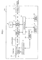
- Fig. 1 is a block diagram showing a configuration of the optical disc reproducing apparatus according to one embodiment of the present invention.
- the optical disc reproducing apparatus 100 as shown in Fig. 1 includes, a turntable 1, a spindle motor 2, a servo control section 3, an optical pickup 4, an amplifier 5, a signal processing section 6, a memory control section 7, RAM (Random Access Memory) 8, DAC (Digital to Analog Converter) 9, an output amplifier 10, an output terminal 11, a control section 12, a display section 13, an operating section 14, and a power applying section 15.
- a CD reproducing portion and a jog dial portion as described below are integrally accommodated in one housing (not illustrated).
- the servo control section 3 drives the spindle motor 2 to rotate at a predetermined linear velocity. Further, the servo control section 3 controls a focus servo circuit and a tracking servo circuit (not illustrated) to allow a laser beam from the optical pickup 4 as described below, to accurately trace pit lines on the CD.
- the optical pickup 4 reads the digital audio data from the CD in a state of rotating.
- the digital audio data read by the optical pickup is subjected to waveform shaping and amplified by the amplifier 5, and then, it is inputted to the signal processing section 6.
- the signal processing section 6 performs a processing such as demodulating the digital audio data, extracting an error signal such as a focus error signal and a tracking error signal, and a synchronized signal, and the like. Then, the digital audio data is outputted to the memory control section 7.
- the memory control section 7 stores thus outputted digital audio data in the RAM 8. Further, the memory control section 7 reads the digital audio data stored in the RAM 8, according to an instruction from the control section 12, and outputs the data to the DAC 9. A control according to the control section 12 over the reading speed and reading sequence (reading the audio data in ascending order address or in descending order address) as to the digital audio data stored in the RAM 8 will be described below.
- the DAC 9 converts the digital audio data into an analog audio signal, and outputs the converted signal to the output amplifier 10.
- the analogue audio signal inputted from the DAC 9 is amplified by the output amplifier 10, and is outputted from a speaker and the like connected to the output terminal 11.
- the display section 13 includes a liquid crystal display and the like.
- the display section 13 displays a reproducing time (minute, second, frame) regarding the track currently under reproduction, and also displays attribute information such as a track number. This attribute information is also read as digital data from the CD.
- the operating section 14 provides an interface for a user to perform a desired operational input to the optical disc reproducing apparatus 100.
- the operating section 14 includes, for example, in addition to the jog dial portion as described in detail in the following, a reproducing start button, a reproducing stop button, a setting button for setting a rise time and a pausing time as described below, a designation button for designating a reproducing start time, an eject button and the like.
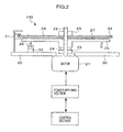
- Fig. 2 is a cross sectional view showing the jog dial portion 140 according to an embodiment of the invention.
- the jog dial portion 140 as shown in Fig. 2 includes, a motor 21, a rotating shaft 22, a fixed holding section 23, a holding section 24, a discal unit 25, a slit section 26, a sheet section 27, an operation discal unit 28, a stopper section 29, a panel 30, a first optical sensor section 31, a second optical sensor section 32, and a slit section 33.
- the jog dial portion 140 is provided in such a manner as exposed on the top surface of the panel 30, which constitutes the housing of the optical disc reproducing apparatus 100 according to the present embodiment.
- the panel 30 which constitutes the housing of the optical disc reproducing apparatus 100 according to the present embodiment.
- other elements such as aforementioned turntable 1 and the like are arranged (not illustrated).
- a user can implement a desired data reproduction by manipulating the jog dial portion 140 in rotating manner, which is exposed on the surface of the housing.
- the motor 21 is fixed on the lower portion of the panel 30.
- the rotating shaft of the motor 21 is connected to the rotating shaft 22.
- the discal unit 25 is configured by a member made of aluminum (Al), for example.
- the fixed holding section 23 is fixed on the rotating shaft 22.
- the holding section 24 is mounted on the top surface of the fixed holding section 23.
- the holding section 24 is a member having a large frictional coefficient, and for example, being an elastic body such as rubber.
- the motor 21 rotates the discal unit 25 at a reference rotational direction (for example, in clockwise direction) and in a reference rotational speed (for example, angular velocity of the turntable in reproducing by an analogue record player).
- the reference rotational speed of the discal unit 25 is set to 54 rpm, for example.
- the discal unit 25 is provided on the holding section 24.
- the slit section 26 is provided on the under surface of the discal unit 25, on the under surface of the discal unit 25, the slit section 26 is provided.
- the slit section 26 is made of, for example, same material as that of the discal unit 25, and is configured by a ring-like plate portion provided nearly perpendicular to the discal unit 25, close to the rim thereof.
- the slit portion 26 includes, for example, rectangle-shaped openings of even size at even intervals.
- the sheet section 27 is provided on the discal unit 25, in such a manner as covering the entire surface thereof. It is preferable that the sheet section 27 is made of a resin material and the like, having a small frictional coefficient and hardly building up static electricity.
- the sheet section 27 is made of a polyester resin member having a diameter of 164 mm, and a weight of approximately 19g.
- the operation discal unit 28 is mounted on the discal unit 25 via the sheet section 27.
- the operation discal unit 28 is made of a member of polyvinylchloride resin (PVC), approximately 43g of weight.
- PVC polyvinylchloride resin
- the operation discal unit 28 has a diameter larger than that of the discal unit 25, so that the periphery of the operation discal unit 28 is arranged to be in outer side of the edge of the discal unit 25.
- the slit sections 33 are provided, each having a rectangle-like shape, and being even size at even intervals. As described below, the user manipulates the operation discal unit 28 in rotating manner to perform a desired operational input.
- the stopper section 29 fixes the holding section 24, the discal unit 25, the sheet section 27, and the operation discal unit 28 to the rotating shaft 22.
- the operation discal unit 28 is rotatable with the discal unit 25, while at the time of user's rotational manipulation, it is constructed to be rotatable independently in sliding manner on the sheet section 27. That is, the operation discal unit 28 is rotatable integrally with the discal unit 25 according to appropriate resistance generated on the sheet section 27, whereas the operation discal unit 28 is capable of being operated freely in rotating manner by sliding on the sheet section 27 at the time of the user's manipulation.
- the first optical sensor section 31 includes two optical sensors, not illustrated, and is fixed on the panel 30 at a position where the slit section 33 can be detected.
- the optical sensors of the first optical sensor section 31 detect the slit section 33 of the operation discal unit 28, and generate a first pulse signal in accordance with the rotating status (rotational speed and rotational direction) of the operation discal unit 28. Then, the optical sensors output the first pulse signals to the control section 12.
- the optical sensors generate the first pulse signals at a frequency corresponding to the frequency at which the slit 33 is detected, and the control section 12 determines the rotational speed of the operation discal unit 28 based on the frequency, for example, the number of pulses received within a predetermined period of time.
- the control section 12 determines the rotational direction of the operation discal unit 28 based on the phase difference of the two first pulse signals.
- the control section 12 controls the memory control section 7, so that the digital audio data stored in the RAM 8 is read at a speed and in a sequence according to the signals, in response to the rotational status thus determined as to the operation discal unit 28.
- the second optical sensor section 32 includes two optical sensors, which are not illustrated, and are fixed on the panel 30 at a position where a slit of the slit section 26 can be detected.
- the optical sensors of the second optical section 32 detect the slit of the slit section 26 of the discal unit 25, and generate a second pulse signal corresponding to the rotational status of the discal unit 25. Then, the optical sensors output the second pulse signal to the control section 12.
- the control section 12 determines the rotational status of the discal unit 25 based on the second pulse signal, in similar manner as the case of the above first pulse signal, and controls the motor 21 so that the rotational speed of the discal unit 25 is maintained at a predetermined rotational speed.
- the power applying section 15 applies a predetermined value of voltage to the motor 21 for a predetermined period of time.
- the control section 12 determines that the operation discal unit 28 restarts rotating in the reference rotational direction after a pause for at least a predetermined period of time, the control section 12 controls the power applying section 15 to apply a predetermined voltage to the motor 21.
- the control section 12 monitors the intervals between the inputs of the first pulse signals and determines based on the intervals that the operation discal unit 28 has paused for at least the predetermined period of time.
- the control section 12 has a timer such as a software timer, and monitors the intervals between the inputs of the first pulse signals. If a status where the intervals are at least a predetermined period of time continues for the predetermined period of time or more, the control section 12 determines that the operation discal unit 28 has paused for at least the predetermined period of time.
- first pulse signals have not been inputted from the first optical sensor section 31 for at least a constant period of time (e.g., 0.4 msec), continues for at least a constant period of time (e.g., 20 msec).
- the control section 12 receives a first signal pulse signal indicating a rotation of the operation discal unit 28 in the reference rotational direction, the control section 12 determines that the operation discal unit 28 restarts rotating, and the control section 12 outputs an application instructing signal to the power applying section 15.
- the power applying section 15 Upon receipt of the application instruction signal from the control section 12, the power applying section 15 applies a predetermined value of voltage (e.g., 8V) to the motor 21, for a predetermined period of time (e.g., 0.2 msec, 20 msec), in addition to the voltage value currently applied. At this moment, the rotational speed of the discal unit 25 is increased, and it rotates at a speed higher than the reference rotational speed temporarily. Accordingly, as described below, the time required for the operation discal unit 28 to reach the reference rotational speed from the pausing status is shortened effectively.
- a predetermined value of voltage e.g. 8V
- a predetermined period of time e.g., 0.2 msec, 20 msec
- a speed for reading the digital audio data from the RAM 8 when the operation discal unit 28 rotates at the reference rotational speed is referred to as a reference reading speed (a reading speed at the time of normal reproduction).
- a sequence for reading the digital audio data from the RAM 8 when the operation discal unit 28 rotates in the reference rotational direction is referred to as a reference reading sequence (a reading sequence at the time of normal reproduction).
- the control section 12 determines the rotational speed of the operation discal unit 28 based on the number of pulses of the first pulse signal, which have been received from the first optical sensor 31 during a constant period of time.
- the control section 12 controls the memory control section 7 so as to make the speed for reading the digital audio data from the RAM 8 slower in accordance with the rotational speed thus determined.
- the first optical sensor section 31 When the rotation of the operation discal unit 28 is stopped, the first optical sensor section 31 does not output the first pulse signal to the control section 12. When received no input of the first pulse signal from the first optical sensor section 31, the control section 12 controls the memory control section 7 to stop reading the digital audio data from the RAM 8.
- the control section 12 determines the rotational speed of the operation discal unit 28 based on the number of pulses of the first pulse signal, which have been inputted from the first optical sensor 31 for a constant period of time. Further, the control section 12 determines a rotational direction of the operation discal unit 28 based on a phase difference between two of the first pulse signals as described above.
- the control section 12 controls via the memory control section 7, the speed and the sequence for reading the audio data from the RAM 8, according to the rotational speed and the rotational direction thus determined.
- the control section 12 determines the rotational speed, and controls the memory control section 7 so as to read the audio data from the RAM 8 at a speed in accordance with the rotational speed thus determined.
- the control section 12 determines the rotational speed and the rotational direction of the operation discal unit 28, and controls the memory control section 7 in accordance with the rotational speed and the rotational direction thus determined.
- the control section 12 controls via the memory control section 7, the reading speed and the reading sequence (reading the audio data in ascending order address or in descending order address) as to the digital audio data stored in the RAM 8.
- the digital audio data read out from the RAM 8 is converted to the analogue audio signal by the DAC 9, amplified by the output amplifier 10, and outputted from a speaker connected to the output terminal 11, as an effective sound like a scratch sound.
- the user can perform the normal reproduction and the special reproduction such as scratch reproduction, as desired.
- the time required for changing from the special reproduction status to the normal reproduction status is shortened effectively.
- the operation discal unit 28 starts to follow the rotation of the discal unit 25, while sliding on the surface of the sheet section 27 and increasing the rotational speed gradually from the pausing status. Therefore, a certain period of time is required for the operation discal unit 28 to reach the reference rotational speed from the pausing status.
- the optical disc reproducing apparatus conducts a reading control at a low speed, in accordance with the rotational speed of the operation discal unit 28. Since such a low speed reading during this period of time is not intended by the user, and there may be a case that the tempo of music goes out of tune. Therefore, it is preferable to make this period of time as short as possible.
- the discal unit 25 is rotated at a speed higher than the reference rotational speed, during a predetermined period of time after the operation discal unit 28 is rotated in reverse direction until the rotational speed reaches the reference rotational speed. Accordingly, the time required for the rotation of the operational discal unit 28 to reach the reference speed can be shortened effectively, since the operation discal unit 28 is given a turning force by the discal unit 25.
- the control section 12 detects timing when the operation discal unit 28 restarts the rotation after a pausing status is ended.
- the pausing status indicates such a status in that after the user completes the rotational manipulation in reverse direction, actually moves his or her hand off the operation discal unit 28, the operation discal unit 28 pauses for a while until it restarts the rotation.
- the control section 12 controls to increase the rotational speed of the discal unit 25.
- control section 12 when the control section 12 receives a first pulse signal indicating a rotation of the operation discal unit 28 in the reference rotational direction, after a state where the first pulse signal has not been inputted from the first optical sensor section 31 (i.e., there has been no rotational operation by the user) for 40 msec or more, for example, the control section 12 outputs an application instructing signal to the power applying section 15.
- the power applying section 15 Upon receipt of the application instructing signal from the control section 12, the power applying section 15 applies to the motor 21, a predetermined voltage value, for example 8V, for a time period, for example 20 msec.
- the motor 21 temporarily accelerates the rotation, by the power thus applied from the power applying section 15, and when the power application is completed, it is rotated at the reference rotational speed.
- control section 12 determines that the operation discal unit 28 rotates at the reference speed and in the reference direction, based on the first pulse signal received from the first optical sensor section 31. At this moment, the control section 12 controls the memory control section 7 to read the digital audio data from the RAM 8, at the reference reading speed and in the reference reading sequence as in the case of normal reproduction.
- Fig. 3 is a diagram showing the first pulse signal outputted from the first optical sensor section 31, the second pulse signal outputted from the second optical sensor section 32, and the power pulse signal outputted to the motor 21 from the power applying section 15. It is to be noted that two signals are included in the first pulse signal and the second pulse signal respectively, but one of the two signals is shown in Fig. 3.
- the operation discal unit 28 is in pausing status, from the time when the user completes the scratch reproduction (A) and then the user's hand is actually moved off the operation discal unit 28, until the time when it starts rotating following the rotation of the discal unit 25.
- the first optical sensor 31 does not generate the first pulse signal.
- the operation discal unit 28 having been in pausing status starts to rotate in the reference rotational direction, while sliding on the surface of the sheet section 27.
- control section 12 When the control section 12 receives the first pulse signal indicating the rotation of the operation discal unit 28 in the reference rotational direction, after a state where the first pulse signal from the first optical sensor section 31 has not been received, for example, for 40 msec, the control section 12 outputs the application instructing signal to the power applying section 15.
- the power applying section 15 applies to the motor 21 the power of voltage value 4V, for example, for a period of 20 msec.
- the rotation of the motor 21 is temporarily accelerated by the power additionally applied from the power applying section 15, and accordingly the rotation of the discal unit 25 is also temporarily accelerated.
- the rotation of the discal unit 25 is temporarily accelerated in a state that the operation discal unit 28 starts rotating while accelerating by sliding on the surface of the sheet section 27, the rotational speed of the operation discal unit 28 is increased significantly. Accordingly, the operation discal unit 28 is capable of reaching the reference rotational speed, within a short period of time in effect, comparing the case where the discal unit 25 is not temporarily accelerated.
- the first optical sensor section 31 When the rotational speed of the operation discal unit 28 reaches the reference rotational speed, the first optical sensor section 31 outputs the first pulse signal at intervals indicating the reference rotational speed and reference rotational direction, which are same as those of the second pulse signal outputted from the second optical sensor section 32. Based on the first signal, the control section 12 determines that the operation discal unit 28 is rotating at the reference rotational speed and in the reference rotational direction. For example, the control section 21 compares the first pulse signals and the second pulse signals, and when the first pulse signals are inputted at the intervals identical to those of the second pulse signals, it determines that the operation discal unit 28 is rotating at the reference rotational speed and in the reference rotational direction.
- the control section 12 controls the memory control section 7 so as to perform the normal reproduction at the point of B as shown in Fig. 3.
- the time period ⁇ t from the point A where the user ends the special reproduction up to the point B where the normal reproduction is restarted is made to be shorter effectively than the time period ⁇ t 0 in the case where the rotation of the discal unit 25 is not accelerated as shown in Fig. 6.
- the time period from the end of the special reproduction to the restart of the normal reproduction is approximately 170 msec, if the power applying section 15 does not apply a voltage when the operation discal unit 28 restarts rotating in the reference rotational direction.
- the power applying section 15 applies voltage of 8V to the motor 21 for a time period of 20 msec, the time period from the end of the special reproduction to the restart of the normal reproduction is approximately 80 msec. Therefore, it is understood that according to the voltage application, the time can be shortened by approximately 90 msec.
- the rotation of the discal unit 25 is temporarily accelerated and then it is rotated at a high speed, thereby significantly increasing the acceleration of the rotation of the operation discal unit 28. Then, the time period required from the end of the special reproduction by the user up to the restart of the normal reproduction is shortened effectively.
- the optical disc reproducing apparatus of the present embodiment when a user completes the special reproduction and restarts the normal reproduction, it is made easier for the user to restart the normal reproduction, with keeping pace with the tempo of music, thereby enhancing the degree of satisfaction of the user.
- the first pulse signal is not generated for 40 msec or more, for example, and then a forward rotation of the operation discal unit 28 is detected, the voltage, for example 8V, is applied to the motor 21, for the time period of 20 msec, for example.
- the time period and the voltage are not limited to the above example, and they can be appropriately selected in accordance with the reference rotational speed, the material, weight, and so on of the discal unit 25 and the like.
- the voltage applying section 15 applies a pulse voltage once to the motor 21.
- the present invention is not limited to this, and two or more pulses may be applied intermittently. In this case, for example, a plurality of pulse voltages may be applied so that the voltage value and/or the pulse width are decreased gradually.
- the timing when the control section 12 instructs the voltage applying section 15 to apply voltage is not limited to the above example.
- the control section 12 stores a standard output pattern or a phase change pattern of the first pulse signal, which indicates the rotational status of the operation discal unit 28, from the special reproduction to the normal reproduction. Then, it is possible to apply voltage when a pattern of the first pulse signal received from the first optical sensor 31 coincides with the pattern thus stored.
- control section 12 applies voltage to the motor 21 via the voltage applying section 15.
- control section 12 may directly control the motor 21, so that the rotational speed of the motor is adjusted to be rotated at a high speed temporarily.
- the present invention is not limited to this, and the operating section and the reading section may be configured separately.
- a reproducing apparatus 410 normal operation and special operation
- the control section 401 of the operating apparatus 400 detects an operational input from a user
- the control section 401 sends to the reproducing apparatus 410 a control signal for the special reproducing operation as described above. Accordingly, it is possible for the user to allow the reproducing apparatus 410 to perform a desired data reproduction, via the operating apparatus 400.
- a CD player for reproducing audio data recorded on a CD has been explained as an example.
- the present invention can be applied to any type of apparatus which performs a reproduction of data recorded on an optical disc.
- it can be applied to an apparatus which reproduces image data recorded on a DVD (Digital Versatile Disc).
- the image data normally reproduced or specially reproduced may be outputted to a display, a projector for home theater use and the like.
- the operating section 400 may be connected to a reproducing apparatus for other magnetic and/or optical recording medium such as a magnetic disc. Accordingly, it is possible to construct such that reproducing is made from the recording medium and a user manipulates reading and outputting of data stored in the memory.
Landscapes
- Signal Processing For Digital Recording And Reproducing (AREA)
- Rotational Drive Of Disk (AREA)
Claims (6)
- Wiedergabevorrichtung, welche umfasst:einen Leseabschnitt (4), welcher auf einem Aufzeichnungsmedium aufgezeichnete Daten liest;einen Speicherabschnitt (8), welcher die durch den Leseabschnitt (4) gelesenen Daten speichert;einen Wiedergabeabschnitt (7), welcher die in dem Speicherabschnitt (8) gespeicherten Daten ausliest und wiedergibt;eine Diskeinheit (25), welche von einem Antriebsabschnitt (21) bei einer Referenzrotationsgeschwindigkeit und in eine Referenzrotationsrichtung rotiert wird;eine Betriebsdiskeinheit (28), welche auf der Diskeinheit (25) aufgebracht ist, um gleitend Änderungen der Rotation der Diskeinheit (25) zu folgen, und einen Befehl empfängt bezüglich einer Wiedergabereihenfolgerichtung und einer Wiedergabegeschwindigkeit der in dem Aufzeichnungsmedium aufgezeichneten Daten, entsprechend einer Rotationsrichtung und einer Rotationsgeschwindigkeit, welche von einem Benutzer vorgegeben sind;einen Sensorabschnitt (31), welcher ein Impulssignal entsprechend der Rotationsrichtung und der Rotationsgeschwindigkeit an die Betriebsdiskeinheit (28) ausgibt; undeinen Steuerabschnitt (12), welcher die Rotationsrichtung und die Rotationsgeschwindigkeit der Betriebsdiskeinheit (28) bestimmt entsprechend dem Impulssignal aus dem Sensorabschnitt (31), und den Wiedergabeabschnitt (7) steuert, um Daten aus dem Speicherabschnitt (8) auszulesen und um die Daten entsprechend der so bestimmten Rotationsrichtung und Rotationsgeschwindigkeit wiederzugeben,dadurch gekennzeichnet, dasswenn der Steuerabschnitt (12) bestimmt, dass die Betriebsdiskeinheit (28) in die Referenzrotationsrichtung zu rotieren beginnt, nach dem Anhalten für wenigstens einen vorbestimmten Zeitraum, nach Bestimmen der Rotationsrichtung und der Rotationsgeschwindigkeit der Betriebsdiskeinheit (28), basierend auf dem Impulssignal des Sensorabschnitts (31), steuert der Steuerabschnitt (12) den Antriebsabschnitt (21), um die Diskeinheit (25) bei einer Geschwindigkeit höher als der Referenzrotationsgeschwindigkeit für einen vorbestimmten Zeitraum zu rotieren.
- Wiedergabevorrichtung nach Anspruch 1, bei welcher
der Steuerabschnitt (12) eine Steuerung bereitstellt, um eine Impulsspannung eines vorbestimmten Spannungswertes auf den Antriebsabschnitt (21) anzuwenden, so dass die Diskeinheit (25) bei einer höheren Geschwindigkeit rotiert wird. - Betriebsvorrichtung zur Wiedergabe, welche umfasst:eine Diskeinheit (25), welche von einem Antriebsabschnitt (21) bei einer Referenzrotationsgeschwindigkeit und in einer Referenzrotationsrichtung rotiert wird;eine Betriebsdiskeinheit (28), welche auf der Diskeinheit (25) aufgebracht ist, um gleitend Änderungen der Rotation der Diskeinheit (25) zu folgen, und auf eine solche Weise konfiguriert ist, um in eine Rotationsrichtung und bei einer Rotationsgeschwindigkeit, wie von einem Benutzer gewünscht, rotiert zu werden, so dass eine extern verbundene Datenwiedergabevorrichtung eine gewünschte Datenwiedergabe ausführt;einen Sensorabschnitt (31), welcher ein Impulssignal entsprechend der Rotationsrichtung und der Rotationsgeschwindigkeit der Betriebsdiskeinheit (28) ausgibt; undeinen Steuerabschnitt (12), welcher die Rotationsrichtung und die Rotationsgeschwindigkeit der Betriebsdiskeinheit (28) basierend auf dem Impulssignal des Sensorabschnitts bestimmt,dadurch gekennzeichnet, dass, wenn der Steuerabschnitt (12) bestimmt, dass die Betriebsdiskeinheit (28) in die Referenzrotationsrichtung zu rotieren beginnt, nach dem Anhalten für wenigstens einen vorbestimmten Zeitraum, der Steuerabschnitt (12) den Antriebsabschnitt (21) steuert, um die Diskeinheit (25) bei einer höheren Geschwindigkeit als der Referenzrotationsgeschwindigkeit für einen vorbestimmten Zeitraum zu rotieren.
- Betriebsvorrichtung zur Wiedergabe nach Anspruch 3, bei welcher
der Steuerabschnitt (12) eine Steuerung bereitstellt, um eine Impulsspannung eines vorbestimmten Spannungswertes auf den Antriebsabschnitt (21) anzuwenden, so dass die Diskeinheit (25) bei einer höheren Geschwindigkeit rotiert wird. - Wiedergabeverfahren in einer Wiedergabevorrichtung mit einem Leseabschnitt (4), welcher auf einem Aufzeichnungsmedium aufgezeichnete Daten liest, einem Speicherabschnitt (8), welcher die durch den Leseabschnitt (4) gelesenen Daten speichert, einen Wiedergabeabschnitt (7), welcher die in dem Speicherabschnitt (8) gespeicherten Daten ausliest und wiedergibt, und eine Diskeinheit (25), welche von einem Antriebsabschnitt (21) bei einer Referenzrotationsgeschwindigkeit und in eine Referenzrotationsrichtung rotiert wird, wobei das Verfahren umfasst:Empfangen eines Befehls von einem Benutzer bezüglich einer Wiedergabereihenfolgerichtung und einer Wiedergabegeschwindigkeit der Daten, über eine Betriebsdiskeinheit (28), welche auf der Diskeinheit (25) aufgebracht ist, um gleitend Änderungen der Rotation der Diskeinheit (25) zu folgen, und auf einer solche Weise konfiguriert ist, um in eine Rotationsrichtung bei einer Rotationsgeschwindigkeit, wie von dem Benutzer gewünscht, rotiert zu werden;Empfangen eines Impulssignals, welches ausgegeben wird entsprechend der Rotationsrichtung und der Rotationsgeschwindigkeit der Betriebsdiskeinheit (28), welche entsprechend des empfangenen Befehls rotiert;Bestimmen der Rotationsrichtung und Rotationsgeschwindigkeit der Betriebsdiskeinheit (28) entsprechend dem empfangenen Impulssignal; undSteuern einer Wiedergabe in dem Wiedergabeabschnitt (7) entsprechend der so bestimmten Rotationsrichtung und Rotationsgeschwindigkeit,dadurch gekennzeichnet, dass, wenn bestimmt wird, dass die Betriebsdiskeinheit (28) in die Referenzrichtung zu rotieren beginnt, nach dem Anhalten für wenigstens einen vorbestimmten Zeitraum, der Antriebsabschnitt (21) gesteuert wird, um die Diskeinheit (25) bei einer Geschwindigkeit höher als die Referenzrotationsgeschwindigkeit für einen vorbestimmten Zeitraum zu rotieren.
- Wiedergabeverfahren nach Anspruch 5, bei welchem
wenn bestimmt wurde, dass die Betriebsdiskeinheit (28) in die Referenzrotationsrichtung zu rotieren beginnt, nach dem Anhalten für wenigstens einen vorbestimmten Zeitraum, das Steuern Anwenden einer Impulsspannung eines vorbestimmten Spannungswerts auf den Antriebsabschnitt (21) beinhaltet, so dass die Diskeinheit (25) bei einer höheren Geschwindigkeit rotiert wird.
Applications Claiming Priority (6)
| Application Number | Priority Date | Filing Date | Title |
|---|---|---|---|
| JP2003341221 | 2003-09-30 | ||
| JP2003341221 | 2003-09-30 | ||
| JP2003387843 | 2003-11-18 | ||
| JP2003387843 | 2003-11-18 | ||
| JP2004020169A JP4295633B2 (ja) | 2003-09-30 | 2004-01-28 | 再生装置および再生用操作装置ならびに再生方法 |
| JP2004020169 | 2004-01-28 |
Publications (3)
| Publication Number | Publication Date |
|---|---|
| EP1521258A2 EP1521258A2 (de) | 2005-04-06 |
| EP1521258A3 EP1521258A3 (de) | 2006-05-10 |
| EP1521258B1 true EP1521258B1 (de) | 2007-11-07 |
Family
ID=34317247
Family Applications (1)
| Application Number | Title | Priority Date | Filing Date |
|---|---|---|---|
| EP04251505A Expired - Lifetime EP1521258B1 (de) | 2003-09-30 | 2004-03-17 | Wiedergabegerät, Betriebsvorrichtung für Wiedergabe und Wiedergabemethode dafür |
Country Status (4)
| Country | Link |
|---|---|
| US (1) | US7218578B2 (de) |
| EP (1) | EP1521258B1 (de) |
| JP (1) | JP4295633B2 (de) |
| DE (1) | DE602004009877T2 (de) |
Families Citing this family (11)
| Publication number | Priority date | Publication date | Assignee | Title |
|---|---|---|---|---|
| NL1014526C2 (nl) * | 2000-02-29 | 2001-08-30 | N2It Dev B V I O | Schijf te gebruiken in een inrichting voor signaalbewerking, alsmede een dergelijke inrichting. |
| US7010371B2 (en) * | 2002-05-01 | 2006-03-07 | Hanpin Electron Co., Ltd. | Digital audio signal player having a simulated analogue record |
| TW200518045A (en) * | 2003-11-21 | 2005-06-01 | Denon Ltd | Optical disc reproducing apparatus and method |
| JP4300162B2 (ja) * | 2004-07-29 | 2009-07-22 | 株式会社ディーアンドエムホールディングス | 光ディスク再生装置 |
| US7928313B2 (en) * | 2006-10-26 | 2011-04-19 | Stanton Magnetics, Inc. | Variable slippage control for a disc jockey control surface |
| US8110734B2 (en) * | 2008-07-15 | 2012-02-07 | Gibson Guitar Corp. | Position sensitive rotatable DJ control device |
| CN102308335A (zh) * | 2008-12-03 | 2012-01-04 | Gvbb控股股份有限公司 | 回放速度控制装置和回放速度控制方法 |
| US8362349B2 (en) * | 2009-09-11 | 2013-01-29 | Gibson Guitar Corp. | Touch pad disc jockey controller |
| US8169862B1 (en) * | 2010-12-20 | 2012-05-01 | Chin Chen Ho | Turntable having multiple-point touch function for a digital sound-signal device |
| US8729375B1 (en) * | 2013-06-24 | 2014-05-20 | Synth Table Partners | Platter based electronic musical instrument |
| US10593313B1 (en) | 2019-02-14 | 2020-03-17 | Peter Bacigalupo | Platter based electronic musical instrument |
Family Cites Families (6)
| Publication number | Priority date | Publication date | Assignee | Title |
|---|---|---|---|---|
| JP2508972B2 (ja) | 1993-06-28 | 1996-06-19 | カシオ計算機株式会社 | 音響信号処理装置 |
| WO1997001168A1 (en) | 1995-06-20 | 1997-01-09 | Rickli Andre | Digital processing device for audio signal |
| JP3867949B2 (ja) | 1999-11-09 | 2007-01-17 | 株式会社ディーアンドエムホールディングス | ディスク再生装置 |
| JP2003257171A (ja) * | 2002-03-04 | 2003-09-12 | Teac Corp | 再生装置 |
| JP3830873B2 (ja) | 2002-08-21 | 2006-10-11 | 株式会社ディーアンドエムホールディングス | 光ディスク再生装置 |
| US20050052981A1 (en) * | 2003-09-09 | 2005-03-10 | Brian Shim | Record controlled sound playback device |
-
2004
- 2004-01-28 JP JP2004020169A patent/JP4295633B2/ja not_active Expired - Lifetime
- 2004-03-15 US US10/799,637 patent/US7218578B2/en not_active Expired - Lifetime
- 2004-03-17 DE DE602004009877T patent/DE602004009877T2/de not_active Expired - Lifetime
- 2004-03-17 EP EP04251505A patent/EP1521258B1/de not_active Expired - Lifetime
Also Published As
| Publication number | Publication date |
|---|---|
| US7218578B2 (en) | 2007-05-15 |
| JP4295633B2 (ja) | 2009-07-15 |
| DE602004009877D1 (de) | 2007-12-20 |
| JP2005174524A (ja) | 2005-06-30 |
| US20050068867A1 (en) | 2005-03-31 |
| DE602004009877T2 (de) | 2008-08-28 |
| EP1521258A3 (de) | 2006-05-10 |
| EP1521258A2 (de) | 2005-04-06 |
Similar Documents
| Publication | Publication Date | Title |
|---|---|---|
| EP1521258B1 (de) | Wiedergabegerät, Betriebsvorrichtung für Wiedergabe und Wiedergabemethode dafür | |
| US6985418B2 (en) | Optical disk reproducing apparatus | |
| JP4300162B2 (ja) | 光ディスク再生装置 | |
| JP2515662B2 (ja) | 記録媒体再生装置の時間表示方式 | |
| JP4257856B2 (ja) | ディスク再生装置 | |
| JP3830873B2 (ja) | 光ディスク再生装置 | |
| KR100226970B1 (ko) | 디지탈 비디오 디스크 플레이어의 구간 반복 재생 방법 | |
| JP4250566B2 (ja) | 光ディスク再生装置 | |
| JP2005158099A (ja) | 光ディスク再生装置 | |
| JP2005293666A (ja) | 光ディスク再生装置 | |
| JP2006099819A (ja) | 光ディスク再生装置 | |
| JP2005190633A (ja) | 光ディスク再生装置 | |
| JP2000011518A (ja) | 再生装置 | |
| KR0174469B1 (ko) | 씬 인트로기능을 갖는 비디오 컴팩트 디스크 장치의 제어방법 | |
| JP2005276281A (ja) | 光ディスク再生装置 | |
| JP2005174501A (ja) | ディジタル信号再生システム | |
| WO2007080955A1 (ja) | 操作装置及び再生装置 | |
| JPH0366748B2 (de) | ||
| JP2005011421A (ja) | 光ディスク再生装置 | |
| JP2005174439A (ja) | ディジタルオーディオ再生システム | |
| JP2005259275A (ja) | 光ディスク再生装置 | |
| JP2007280436A (ja) | 光ディスク再生装置 | |
| JPH1166729A (ja) | 記録装置 | |
| JPS59107457A (ja) | ディスク再生装置の一時停止装置 | |
| JP2005108289A (ja) | 光ディスク再生装置 |
Legal Events
| Date | Code | Title | Description |
|---|---|---|---|
| PUAI | Public reference made under article 153(3) epc to a published international application that has entered the european phase |
Free format text: ORIGINAL CODE: 0009012 |
|
| AK | Designated contracting states |
Kind code of ref document: A2 Designated state(s): AT BE BG CH CY CZ DE DK EE ES FI FR GB GR HU IE IT LI LU MC NL PL PT RO SE SI SK TR |
|
| AX | Request for extension of the european patent |
Extension state: AL HR LT LV MK |
|
| RAP1 | Party data changed (applicant data changed or rights of an application transferred) |
Owner name: D&M HOLDINGS, INC. |
|
| PUAL | Search report despatched |
Free format text: ORIGINAL CODE: 0009013 |
|
| AK | Designated contracting states |
Kind code of ref document: A3 Designated state(s): AT BE BG CH CY CZ DE DK EE ES FI FR GB GR HU IE IT LI LU MC NL PL PT RO SE SI SK TR |
|
| AX | Request for extension of the european patent |
Extension state: AL LT LV MK |
|
| 17P | Request for examination filed |
Effective date: 20060724 |
|
| 17Q | First examination report despatched |
Effective date: 20060825 |
|
| AKX | Designation fees paid |
Designated state(s): DE FR GB |
|
| GRAP | Despatch of communication of intention to grant a patent |
Free format text: ORIGINAL CODE: EPIDOSNIGR1 |
|
| GRAS | Grant fee paid |
Free format text: ORIGINAL CODE: EPIDOSNIGR3 |
|
| GRAA | (expected) grant |
Free format text: ORIGINAL CODE: 0009210 |
|
| AK | Designated contracting states |
Kind code of ref document: B1 Designated state(s): DE FR GB |
|
| REG | Reference to a national code |
Ref country code: GB Ref legal event code: FG4D |
|
| REF | Corresponds to: |
Ref document number: 602004009877 Country of ref document: DE Date of ref document: 20071220 Kind code of ref document: P |
|
| ET | Fr: translation filed | ||
| PLBE | No opposition filed within time limit |
Free format text: ORIGINAL CODE: 0009261 |
|
| STAA | Information on the status of an ep patent application or granted ep patent |
Free format text: STATUS: NO OPPOSITION FILED WITHIN TIME LIMIT |
|
| 26N | No opposition filed |
Effective date: 20080808 |
|
| REG | Reference to a national code |
Ref country code: GB Ref legal event code: 732E Free format text: REGISTERED BETWEEN 20090402 AND 20090408 |
|
| REG | Reference to a national code |
Ref country code: FR Ref legal event code: TP Owner name: INMUSIC BRANDS, INC., US Effective date: 20140520 |
|
| REG | Reference to a national code |
Ref country code: GB Ref legal event code: 732E Free format text: REGISTERED BETWEEN 20141016 AND 20141022 |
|
| REG | Reference to a national code |
Ref country code: DE Ref legal event code: R082 Ref document number: 602004009877 Country of ref document: DE Representative=s name: RAFFAY & FLECK PATENTANWAELTE, DE |
|
| REG | Reference to a national code |
Ref country code: DE Ref legal event code: R082 Ref document number: 602004009877 Country of ref document: DE Representative=s name: RAFFAY & FLECK PATENTANWAELTE, DE Effective date: 20150317 Ref country code: DE Ref legal event code: R081 Ref document number: 602004009877 Country of ref document: DE Owner name: INMUSIC BRANDS INC., CUMBERLAND, US Free format text: FORMER OWNER: D&M HOLDINGS, INC., SAGAMIHARA, KANAGAWA, JP Effective date: 20150317 |
|
| REG | Reference to a national code |
Ref country code: DE Ref legal event code: R082 Ref document number: 602004009877 Country of ref document: DE |
|
| REG | Reference to a national code |
Ref country code: FR Ref legal event code: PLFP Year of fee payment: 13 |
|
| REG | Reference to a national code |
Ref country code: FR Ref legal event code: PLFP Year of fee payment: 14 |
|
| REG | Reference to a national code |
Ref country code: FR Ref legal event code: PLFP Year of fee payment: 15 |
|
| PGFP | Annual fee paid to national office [announced via postgrant information from national office to epo] |
Ref country code: DE Payment date: 20180306 Year of fee payment: 15 Ref country code: GB Payment date: 20180314 Year of fee payment: 15 |
|
| PGFP | Annual fee paid to national office [announced via postgrant information from national office to epo] |
Ref country code: FR Payment date: 20180222 Year of fee payment: 15 |
|
| REG | Reference to a national code |
Ref country code: DE Ref legal event code: R119 Ref document number: 602004009877 Country of ref document: DE |
|
| GBPC | Gb: european patent ceased through non-payment of renewal fee |
Effective date: 20190317 |
|
| PG25 | Lapsed in a contracting state [announced via postgrant information from national office to epo] |
Ref country code: GB Free format text: LAPSE BECAUSE OF NON-PAYMENT OF DUE FEES Effective date: 20190317 Ref country code: DE Free format text: LAPSE BECAUSE OF NON-PAYMENT OF DUE FEES Effective date: 20191001 |
|
| PG25 | Lapsed in a contracting state [announced via postgrant information from national office to epo] |
Ref country code: FR Free format text: LAPSE BECAUSE OF NON-PAYMENT OF DUE FEES Effective date: 20190331 |