EP1518705A2 - Matériau d'enregistrement par transfert thermique - Google Patents
Matériau d'enregistrement par transfert thermique Download PDFInfo
- Publication number
- EP1518705A2 EP1518705A2 EP04255650A EP04255650A EP1518705A2 EP 1518705 A2 EP1518705 A2 EP 1518705A2 EP 04255650 A EP04255650 A EP 04255650A EP 04255650 A EP04255650 A EP 04255650A EP 1518705 A2 EP1518705 A2 EP 1518705A2
- Authority
- EP
- European Patent Office
- Prior art keywords
- group
- thermal transfer
- dye
- layer
- resins
- Prior art date
- Legal status (The legal status is an assumption and is not a legal conclusion. Google has not performed a legal analysis and makes no representation as to the accuracy of the status listed.)
- Withdrawn
Links
- 238000012546 transfer Methods 0.000 title claims abstract description 148
- 239000000463 material Substances 0.000 title claims abstract description 47
- 229920005989 resin Polymers 0.000 claims abstract description 133
- 239000011347 resin Substances 0.000 claims abstract description 133
- 239000011230 binding agent Substances 0.000 claims abstract description 61
- 238000002844 melting Methods 0.000 claims abstract description 35
- 230000008018 melting Effects 0.000 claims abstract description 35
- 150000001875 compounds Chemical class 0.000 claims description 33
- 230000009477 glass transition Effects 0.000 claims description 16
- 229910021645 metal ion Inorganic materials 0.000 claims description 14
- 229910052751 metal Inorganic materials 0.000 claims description 11
- 239000002184 metal Substances 0.000 claims description 11
- 238000010438 heat treatment Methods 0.000 claims description 9
- 230000004927 fusion Effects 0.000 claims description 8
- 239000010410 layer Substances 0.000 description 147
- 239000000975 dye Substances 0.000 description 129
- -1 silver halide Chemical class 0.000 description 109
- 239000011241 protective layer Substances 0.000 description 37
- 239000000758 substrate Substances 0.000 description 37
- 238000007639 printing Methods 0.000 description 31
- 239000000123 paper Substances 0.000 description 30
- 239000003795 chemical substances by application Substances 0.000 description 27
- 238000000034 method Methods 0.000 description 24
- 125000000217 alkyl group Chemical group 0.000 description 23
- 239000006096 absorbing agent Substances 0.000 description 20
- 125000001424 substituent group Chemical group 0.000 description 20
- 239000007788 liquid Substances 0.000 description 18
- 229920001296 polysiloxane Polymers 0.000 description 18
- 239000008199 coating composition Substances 0.000 description 17
- 230000000052 comparative effect Effects 0.000 description 16
- 229920001577 copolymer Polymers 0.000 description 15
- 239000011229 interlayer Substances 0.000 description 15
- 239000011859 microparticle Substances 0.000 description 15
- GWEVSGVZZGPLCZ-UHFFFAOYSA-N Titan oxide Chemical compound O=[Ti]=O GWEVSGVZZGPLCZ-UHFFFAOYSA-N 0.000 description 14
- 239000013522 chelant Substances 0.000 description 14
- ZWEHNKRNPOVVGH-UHFFFAOYSA-N 2-Butanone Chemical compound CCC(C)=O ZWEHNKRNPOVVGH-UHFFFAOYSA-N 0.000 description 12
- RAXXELZNTBOGNW-UHFFFAOYSA-N imidazole Natural products C1=CNC=N1 RAXXELZNTBOGNW-UHFFFAOYSA-N 0.000 description 12
- 229920002554 vinyl polymer Polymers 0.000 description 12
- 125000003118 aryl group Chemical group 0.000 description 11
- 125000000623 heterocyclic group Chemical group 0.000 description 11
- 239000002904 solvent Substances 0.000 description 11
- 125000004429 atom Chemical group 0.000 description 10
- 125000001449 isopropyl group Chemical group [H]C([H])([H])C([H])(*)C([H])([H])[H] 0.000 description 10
- 230000003287 optical effect Effects 0.000 description 10
- 239000002985 plastic film Substances 0.000 description 10
- 229920006255 plastic film Polymers 0.000 description 10
- OGIDPMRJRNCKJF-UHFFFAOYSA-N titanium oxide Inorganic materials [Ti]=O OGIDPMRJRNCKJF-UHFFFAOYSA-N 0.000 description 10
- UHOVQNZJYSORNB-UHFFFAOYSA-N Benzene Chemical compound C1=CC=CC=C1 UHOVQNZJYSORNB-UHFFFAOYSA-N 0.000 description 9
- 239000004793 Polystyrene Substances 0.000 description 9
- JUJWROOIHBZHMG-UHFFFAOYSA-N Pyridine Chemical compound C1=CC=NC=C1 JUJWROOIHBZHMG-UHFFFAOYSA-N 0.000 description 9
- YXFVVABEGXRONW-UHFFFAOYSA-N Toluene Chemical compound CC1=CC=CC=C1 YXFVVABEGXRONW-UHFFFAOYSA-N 0.000 description 9
- 229920002678 cellulose Polymers 0.000 description 9
- 239000001913 cellulose Substances 0.000 description 9
- 229920002223 polystyrene Polymers 0.000 description 9
- 125000000999 tert-butyl group Chemical group [H]C([H])([H])C(*)(C([H])([H])[H])C([H])([H])[H] 0.000 description 9
- PXHVJJICTQNCMI-UHFFFAOYSA-N Nickel Chemical compound [Ni] PXHVJJICTQNCMI-UHFFFAOYSA-N 0.000 description 8
- 239000004743 Polypropylene Substances 0.000 description 8
- 238000005282 brightening Methods 0.000 description 8
- 238000000576 coating method Methods 0.000 description 8
- 230000005865 ionizing radiation Effects 0.000 description 8
- 239000000203 mixture Substances 0.000 description 8
- 229920001225 polyester resin Polymers 0.000 description 8
- 229920001155 polypropylene Polymers 0.000 description 8
- 239000004094 surface-active agent Substances 0.000 description 8
- 125000000391 vinyl group Chemical group [H]C([*])=C([H])[H] 0.000 description 8
- LFQSCWFLJHTTHZ-UHFFFAOYSA-N Ethanol Chemical compound CCO LFQSCWFLJHTTHZ-UHFFFAOYSA-N 0.000 description 7
- 239000004372 Polyvinyl alcohol Substances 0.000 description 7
- 239000000654 additive Substances 0.000 description 7
- 239000011248 coating agent Substances 0.000 description 7
- 125000002887 hydroxy group Chemical group [H]O* 0.000 description 7
- 229920002037 poly(vinyl butyral) polymer Polymers 0.000 description 7
- 239000004417 polycarbonate Substances 0.000 description 7
- 229920000515 polycarbonate Polymers 0.000 description 7
- 229920002451 polyvinyl alcohol Polymers 0.000 description 7
- 238000003847 radiation curing Methods 0.000 description 7
- 239000007787 solid Substances 0.000 description 7
- OKKJLVBELUTLKV-UHFFFAOYSA-N Methanol Chemical compound OC OKKJLVBELUTLKV-UHFFFAOYSA-N 0.000 description 6
- 125000002777 acetyl group Chemical group [H]C([H])([H])C(*)=O 0.000 description 6
- 230000015572 biosynthetic process Effects 0.000 description 6
- 125000004432 carbon atom Chemical group C* 0.000 description 6
- 230000000694 effects Effects 0.000 description 6
- 238000003475 lamination Methods 0.000 description 6
- 125000002496 methyl group Chemical group [H]C([H])([H])* 0.000 description 6
- 229920000728 polyester Polymers 0.000 description 6
- 239000004645 polyester resin Substances 0.000 description 6
- 239000005020 polyethylene terephthalate Substances 0.000 description 6
- 229920000139 polyethylene terephthalate Polymers 0.000 description 6
- 238000007669 thermal treatment Methods 0.000 description 6
- XLYOFNOQVPJJNP-UHFFFAOYSA-N water Substances O XLYOFNOQVPJJNP-UHFFFAOYSA-N 0.000 description 6
- KFZMGEQAYNKOFK-UHFFFAOYSA-N Isopropanol Chemical compound CC(C)O KFZMGEQAYNKOFK-UHFFFAOYSA-N 0.000 description 5
- VYPSYNLAJGMNEJ-UHFFFAOYSA-N Silicium dioxide Chemical compound O=[Si]=O VYPSYNLAJGMNEJ-UHFFFAOYSA-N 0.000 description 5
- XTXRWKRVRITETP-UHFFFAOYSA-N Vinyl acetate Chemical compound CC(=O)OC=C XTXRWKRVRITETP-UHFFFAOYSA-N 0.000 description 5
- BZHJMEDXRYGGRV-UHFFFAOYSA-N Vinyl chloride Chemical compound ClC=C BZHJMEDXRYGGRV-UHFFFAOYSA-N 0.000 description 5
- DHKHKXVYLBGOIT-UHFFFAOYSA-N acetaldehyde Diethyl Acetal Natural products CCOC(C)OCC DHKHKXVYLBGOIT-UHFFFAOYSA-N 0.000 description 5
- 125000004442 acylamino group Chemical group 0.000 description 5
- 125000003545 alkoxy group Chemical group 0.000 description 5
- 125000003277 amino group Chemical group 0.000 description 5
- 125000004093 cyano group Chemical group *C#N 0.000 description 5
- 125000001495 ethyl group Chemical group [H]C([H])([H])C([H])([H])* 0.000 description 5
- 238000011156 evaluation Methods 0.000 description 5
- 125000004435 hydrogen atom Chemical group [H]* 0.000 description 5
- 229920000554 ionomer Polymers 0.000 description 5
- 238000002156 mixing Methods 0.000 description 5
- 229910052759 nickel Inorganic materials 0.000 description 5
- 229920005668 polycarbonate resin Polymers 0.000 description 5
- 239000004431 polycarbonate resin Substances 0.000 description 5
- 229920000642 polymer Polymers 0.000 description 5
- 239000004800 polyvinyl chloride Substances 0.000 description 5
- 229920005604 random copolymer Polymers 0.000 description 5
- 238000012216 screening Methods 0.000 description 5
- 229920003002 synthetic resin Polymers 0.000 description 5
- 239000000057 synthetic resin Substances 0.000 description 5
- 239000004698 Polyethylene Substances 0.000 description 4
- 229920001328 Polyvinylidene chloride Polymers 0.000 description 4
- 229920002433 Vinyl chloride-vinyl acetate copolymer Polymers 0.000 description 4
- 125000002252 acyl group Chemical group 0.000 description 4
- 125000003342 alkenyl group Chemical group 0.000 description 4
- 125000004453 alkoxycarbonyl group Chemical group 0.000 description 4
- 150000001412 amines Chemical class 0.000 description 4
- 239000003963 antioxidant agent Substances 0.000 description 4
- 230000005540 biological transmission Effects 0.000 description 4
- 238000006243 chemical reaction Methods 0.000 description 4
- 125000000753 cycloalkyl group Chemical group 0.000 description 4
- 229910052731 fluorine Inorganic materials 0.000 description 4
- 125000005843 halogen group Chemical group 0.000 description 4
- 238000004519 manufacturing process Methods 0.000 description 4
- 239000000178 monomer Substances 0.000 description 4
- 125000004123 n-propyl group Chemical group [H]C([H])([H])C([H])([H])C([H])([H])* 0.000 description 4
- 229920003229 poly(methyl methacrylate) Polymers 0.000 description 4
- 229920000573 polyethylene Polymers 0.000 description 4
- 239000004926 polymethyl methacrylate Substances 0.000 description 4
- 239000011118 polyvinyl acetate Substances 0.000 description 4
- 229920002689 polyvinyl acetate Polymers 0.000 description 4
- 229920000915 polyvinyl chloride Polymers 0.000 description 4
- 239000005033 polyvinylidene chloride Substances 0.000 description 4
- UMJSCPRVCHMLSP-UHFFFAOYSA-N pyridine Natural products COC1=CC=CN=C1 UMJSCPRVCHMLSP-UHFFFAOYSA-N 0.000 description 4
- YGSDEFSMJLZEOE-UHFFFAOYSA-N salicylic acid Chemical compound OC(=O)C1=CC=CC=C1O YGSDEFSMJLZEOE-UHFFFAOYSA-N 0.000 description 4
- 238000010023 transfer printing Methods 0.000 description 4
- 238000011282 treatment Methods 0.000 description 4
- QTBSBXVTEAMEQO-UHFFFAOYSA-N Acetic acid Chemical compound CC(O)=O QTBSBXVTEAMEQO-UHFFFAOYSA-N 0.000 description 3
- XEKOWRVHYACXOJ-UHFFFAOYSA-N Ethyl acetate Chemical compound CCOC(C)=O XEKOWRVHYACXOJ-UHFFFAOYSA-N 0.000 description 3
- LYCAIKOWRPUZTN-UHFFFAOYSA-N Ethylene glycol Chemical compound OCCO LYCAIKOWRPUZTN-UHFFFAOYSA-N 0.000 description 3
- FZWLAAWBMGSTSO-UHFFFAOYSA-N Thiazole Chemical compound C1=CSC=N1 FZWLAAWBMGSTSO-UHFFFAOYSA-N 0.000 description 3
- 239000002253 acid Substances 0.000 description 3
- 239000000853 adhesive Substances 0.000 description 3
- 230000001070 adhesive effect Effects 0.000 description 3
- 239000012790 adhesive layer Substances 0.000 description 3
- 125000000304 alkynyl group Chemical group 0.000 description 3
- 125000005110 aryl thio group Chemical group 0.000 description 3
- 125000004104 aryloxy group Chemical group 0.000 description 3
- RWCCWEUUXYIKHB-UHFFFAOYSA-N benzophenone Chemical compound C=1C=CC=CC=1C(=O)C1=CC=CC=C1 RWCCWEUUXYIKHB-UHFFFAOYSA-N 0.000 description 3
- 239000012965 benzophenone Substances 0.000 description 3
- QRUDEWIWKLJBPS-UHFFFAOYSA-N benzotriazole Chemical compound C1=CC=C2N[N][N]C2=C1 QRUDEWIWKLJBPS-UHFFFAOYSA-N 0.000 description 3
- 239000012964 benzotriazole Substances 0.000 description 3
- 125000003917 carbamoyl group Chemical group [H]N([H])C(*)=O 0.000 description 3
- 125000003178 carboxy group Chemical group [H]OC(*)=O 0.000 description 3
- 229920002301 cellulose acetate Polymers 0.000 description 3
- 238000001723 curing Methods 0.000 description 3
- 238000009820 dry lamination Methods 0.000 description 3
- 150000002148 esters Chemical class 0.000 description 3
- 238000007756 gravure coating Methods 0.000 description 3
- VLKZOEOYAKHREP-UHFFFAOYSA-N n-Hexane Chemical compound CCCCCC VLKZOEOYAKHREP-UHFFFAOYSA-N 0.000 description 3
- 125000004108 n-butyl group Chemical group [H]C([H])([H])C([H])([H])C([H])([H])C([H])([H])* 0.000 description 3
- 125000000449 nitro group Chemical group [O-][N+](*)=O 0.000 description 3
- 150000003014 phosphoric acid esters Chemical class 0.000 description 3
- 229920002647 polyamide Polymers 0.000 description 3
- 229920006122 polyamide resin Polymers 0.000 description 3
- 229920001721 polyimide Polymers 0.000 description 3
- 238000006116 polymerization reaction Methods 0.000 description 3
- 229920000098 polyolefin Polymers 0.000 description 3
- 229920002635 polyurethane Polymers 0.000 description 3
- 239000004814 polyurethane Substances 0.000 description 3
- 229920000036 polyvinylpyrrolidone Polymers 0.000 description 3
- 239000001267 polyvinylpyrrolidone Substances 0.000 description 3
- 235000013855 polyvinylpyrrolidone Nutrition 0.000 description 3
- 238000002360 preparation method Methods 0.000 description 3
- 230000004044 response Effects 0.000 description 3
- 150000003839 salts Chemical class 0.000 description 3
- 125000002914 sec-butyl group Chemical group [H]C([H])([H])C([H])([H])C([H])(*)C([H])([H])[H] 0.000 description 3
- 229920002545 silicone oil Polymers 0.000 description 3
- 238000000859 sublimation Methods 0.000 description 3
- 230000008022 sublimation Effects 0.000 description 3
- 239000000126 substance Substances 0.000 description 3
- 229910052623 talc Inorganic materials 0.000 description 3
- BFKJFAAPBSQJPD-UHFFFAOYSA-N tetrafluoroethene Chemical group FC(F)=C(F)F BFKJFAAPBSQJPD-UHFFFAOYSA-N 0.000 description 3
- 229920002803 thermoplastic polyurethane Polymers 0.000 description 3
- 239000011800 void material Substances 0.000 description 3
- 229910052725 zinc Inorganic materials 0.000 description 3
- 239000011701 zinc Substances 0.000 description 3
- RTTZISZSHSCFRH-UHFFFAOYSA-N 1,3-bis(isocyanatomethyl)benzene Chemical compound O=C=NCC1=CC=CC(CN=C=O)=C1 RTTZISZSHSCFRH-UHFFFAOYSA-N 0.000 description 2
- XNMQEEKYCVKGBD-UHFFFAOYSA-N 2-butyne Chemical compound CC#CC XNMQEEKYCVKGBD-UHFFFAOYSA-N 0.000 description 2
- CSCPPACGZOOCGX-UHFFFAOYSA-N Acetone Chemical compound CC(C)=O CSCPPACGZOOCGX-UHFFFAOYSA-N 0.000 description 2
- OKTJSMMVPCPJKN-UHFFFAOYSA-N Carbon Chemical group [C] OKTJSMMVPCPJKN-UHFFFAOYSA-N 0.000 description 2
- 229920002134 Carboxymethyl cellulose Polymers 0.000 description 2
- 229920003043 Cellulose fiber Polymers 0.000 description 2
- VGGSQFUCUMXWEO-UHFFFAOYSA-N Ethene Chemical compound C=C VGGSQFUCUMXWEO-UHFFFAOYSA-N 0.000 description 2
- 239000001856 Ethyl cellulose Substances 0.000 description 2
- ZZSNKZQZMQGXPY-UHFFFAOYSA-N Ethyl cellulose Chemical compound CCOCC1OC(OC)C(OCC)C(OCC)C1OC1C(O)C(O)C(OC)C(CO)O1 ZZSNKZQZMQGXPY-UHFFFAOYSA-N 0.000 description 2
- 239000005977 Ethylene Substances 0.000 description 2
- YCKRFDGAMUMZLT-UHFFFAOYSA-N Fluorine atom Chemical compound [F] YCKRFDGAMUMZLT-UHFFFAOYSA-N 0.000 description 2
- YLQBMQCUIZJEEH-UHFFFAOYSA-N Furan Chemical compound C=1C=COC=1 YLQBMQCUIZJEEH-UHFFFAOYSA-N 0.000 description 2
- YNAVUWVOSKDBBP-UHFFFAOYSA-N Morpholine Chemical group C1COCCN1 YNAVUWVOSKDBBP-UHFFFAOYSA-N 0.000 description 2
- LRHPLDYGYMQRHN-UHFFFAOYSA-N N-Butanol Chemical compound CCCCO LRHPLDYGYMQRHN-UHFFFAOYSA-N 0.000 description 2
- 239000000020 Nitrocellulose Substances 0.000 description 2
- ISWSIDIOOBJBQZ-UHFFFAOYSA-N Phenol Chemical compound OC1=CC=CC=C1 ISWSIDIOOBJBQZ-UHFFFAOYSA-N 0.000 description 2
- 239000004695 Polyether sulfone Substances 0.000 description 2
- 239000004642 Polyimide Substances 0.000 description 2
- KYQCOXFCLRTKLS-UHFFFAOYSA-N Pyrazine Chemical compound C1=CN=CC=N1 KYQCOXFCLRTKLS-UHFFFAOYSA-N 0.000 description 2
- WTKZEGDFNFYCGP-UHFFFAOYSA-N Pyrazole Chemical compound C=1C=NNC=1 WTKZEGDFNFYCGP-UHFFFAOYSA-N 0.000 description 2
- CZPWVGJYEJSRLH-UHFFFAOYSA-N Pyrimidine Chemical compound C1=CN=CN=C1 CZPWVGJYEJSRLH-UHFFFAOYSA-N 0.000 description 2
- KAESVJOAVNADME-UHFFFAOYSA-N Pyrrole Chemical compound C=1C=CNC=1 KAESVJOAVNADME-UHFFFAOYSA-N 0.000 description 2
- 229920002125 Sokalan® Polymers 0.000 description 2
- PPBRXRYQALVLMV-UHFFFAOYSA-N Styrene Chemical compound C=CC1=CC=CC=C1 PPBRXRYQALVLMV-UHFFFAOYSA-N 0.000 description 2
- YTPLMLYBLZKORZ-UHFFFAOYSA-N Thiophene Chemical compound C=1C=CSC=1 YTPLMLYBLZKORZ-UHFFFAOYSA-N 0.000 description 2
- XLOMVQKBTHCTTD-UHFFFAOYSA-N Zinc monoxide Chemical compound [Zn]=O XLOMVQKBTHCTTD-UHFFFAOYSA-N 0.000 description 2
- FJWGYAHXMCUOOM-QHOUIDNNSA-N [(2s,3r,4s,5r,6r)-2-[(2r,3r,4s,5r,6s)-4,5-dinitrooxy-2-(nitrooxymethyl)-6-[(2r,3r,4s,5r,6s)-4,5,6-trinitrooxy-2-(nitrooxymethyl)oxan-3-yl]oxyoxan-3-yl]oxy-3,5-dinitrooxy-6-(nitrooxymethyl)oxan-4-yl] nitrate Chemical compound O([C@@H]1O[C@@H]([C@H]([C@H](O[N+]([O-])=O)[C@H]1O[N+]([O-])=O)O[C@H]1[C@@H]([C@@H](O[N+]([O-])=O)[C@H](O[N+]([O-])=O)[C@@H](CO[N+]([O-])=O)O1)O[N+]([O-])=O)CO[N+](=O)[O-])[C@@H]1[C@@H](CO[N+]([O-])=O)O[C@@H](O[N+]([O-])=O)[C@H](O[N+]([O-])=O)[C@H]1O[N+]([O-])=O FJWGYAHXMCUOOM-QHOUIDNNSA-N 0.000 description 2
- 150000008360 acrylonitriles Chemical class 0.000 description 2
- 125000003647 acryloyl group Chemical group O=C([*])C([H])=C([H])[H] 0.000 description 2
- 125000001931 aliphatic group Chemical group 0.000 description 2
- 125000004414 alkyl thio group Chemical group 0.000 description 2
- 125000004397 aminosulfonyl group Chemical group NS(=O)(=O)* 0.000 description 2
- 125000002490 anilino group Chemical group [H]N(*)C1=C([H])C([H])=C([H])C([H])=C1[H] 0.000 description 2
- 150000001450 anions Chemical class 0.000 description 2
- 150000004945 aromatic hydrocarbons Chemical group 0.000 description 2
- 230000004888 barrier function Effects 0.000 description 2
- WPYMKLBDIGXBTP-UHFFFAOYSA-N benzoic acid Chemical compound OC(=O)C1=CC=CC=C1 WPYMKLBDIGXBTP-UHFFFAOYSA-N 0.000 description 2
- 125000001951 carbamoylamino group Chemical group C(N)(=O)N* 0.000 description 2
- 125000002915 carbonyl group Chemical group [*:2]C([*:1])=O 0.000 description 2
- 239000001768 carboxy methyl cellulose Substances 0.000 description 2
- 235000010948 carboxy methyl cellulose Nutrition 0.000 description 2
- 239000008112 carboxymethyl-cellulose Substances 0.000 description 2
- 230000009920 chelation Effects 0.000 description 2
- 229910052801 chlorine Inorganic materials 0.000 description 2
- 125000001309 chloro group Chemical group Cl* 0.000 description 2
- 229910052804 chromium Inorganic materials 0.000 description 2
- 239000003086 colorant Substances 0.000 description 2
- 229910052802 copper Inorganic materials 0.000 description 2
- 239000010949 copper Substances 0.000 description 2
- 238000003851 corona treatment Methods 0.000 description 2
- ZYGHJZDHTFUPRJ-UHFFFAOYSA-N coumarin Chemical compound C1=CC=C2OC(=O)C=CC2=C1 ZYGHJZDHTFUPRJ-UHFFFAOYSA-N 0.000 description 2
- 238000004132 cross linking Methods 0.000 description 2
- 125000000113 cyclohexyl group Chemical group [H]C1([H])C([H])([H])C([H])([H])C([H])(*)C([H])([H])C1([H])[H] 0.000 description 2
- 239000006185 dispersion Substances 0.000 description 2
- 238000009826 distribution Methods 0.000 description 2
- 239000000839 emulsion Substances 0.000 description 2
- 238000005516 engineering process Methods 0.000 description 2
- 230000002708 enhancing effect Effects 0.000 description 2
- 125000003700 epoxy group Chemical group 0.000 description 2
- 229920001249 ethyl cellulose Polymers 0.000 description 2
- 235000019325 ethyl cellulose Nutrition 0.000 description 2
- 239000000945 filler Substances 0.000 description 2
- 239000011737 fluorine Substances 0.000 description 2
- 125000001153 fluoro group Chemical group F* 0.000 description 2
- 239000011086 glassine Substances 0.000 description 2
- ZXEKIIBDNHEJCQ-UHFFFAOYSA-N isobutanol Chemical compound CC(C)CO ZXEKIIBDNHEJCQ-UHFFFAOYSA-N 0.000 description 2
- IQPQWNKOIGAROB-UHFFFAOYSA-N isocyanate group Chemical group [N-]=C=O IQPQWNKOIGAROB-UHFFFAOYSA-N 0.000 description 2
- 239000003446 ligand Substances 0.000 description 2
- 239000004611 light stabiliser Substances 0.000 description 2
- 150000002739 metals Chemical class 0.000 description 2
- 125000002816 methylsulfanyl group Chemical group [H]C([H])([H])S[*] 0.000 description 2
- 125000003136 n-heptyl group Chemical group [H]C([H])([H])C([H])([H])C([H])([H])C([H])([H])C([H])([H])C([H])([H])C([H])([H])* 0.000 description 2
- 125000001280 n-hexyl group Chemical group C(CCCCC)* 0.000 description 2
- 125000000740 n-pentyl group Chemical group [H]C([H])([H])C([H])([H])C([H])([H])C([H])([H])C([H])([H])* 0.000 description 2
- 229920001220 nitrocellulos Polymers 0.000 description 2
- 229910052757 nitrogen Inorganic materials 0.000 description 2
- 125000004433 nitrogen atom Chemical group N* 0.000 description 2
- QUAMTGJKVDWJEQ-UHFFFAOYSA-N octabenzone Chemical compound OC1=CC(OCCCCCCCC)=CC=C1C(=O)C1=CC=CC=C1 QUAMTGJKVDWJEQ-UHFFFAOYSA-N 0.000 description 2
- 125000001820 oxy group Chemical group [*:1]O[*:2] 0.000 description 2
- FJKROLUGYXJWQN-UHFFFAOYSA-N papa-hydroxy-benzoic acid Natural products OC(=O)C1=CC=C(O)C=C1 FJKROLUGYXJWQN-UHFFFAOYSA-N 0.000 description 2
- 239000012188 paraffin wax Substances 0.000 description 2
- 239000002245 particle Substances 0.000 description 2
- 125000001997 phenyl group Chemical group [H]C1=C([H])C([H])=C(*)C([H])=C1[H] 0.000 description 2
- 239000000049 pigment Substances 0.000 description 2
- 229920003023 plastic Polymers 0.000 description 2
- 239000004033 plastic Substances 0.000 description 2
- 239000004014 plasticizer Substances 0.000 description 2
- 229920001643 poly(ether ketone) Polymers 0.000 description 2
- 229920002492 poly(sulfone) Polymers 0.000 description 2
- 239000004584 polyacrylic acid Substances 0.000 description 2
- 229920001707 polybutylene terephthalate Polymers 0.000 description 2
- 229920006393 polyether sulfone Polymers 0.000 description 2
- 229920001228 polyisocyanate Polymers 0.000 description 2
- 239000005056 polyisocyanate Substances 0.000 description 2
- 229920000193 polymethacrylate Polymers 0.000 description 2
- 229920005672 polyolefin resin Polymers 0.000 description 2
- 229920005990 polystyrene resin Polymers 0.000 description 2
- 229920005749 polyurethane resin Polymers 0.000 description 2
- 230000001681 protective effect Effects 0.000 description 2
- 230000005855 radiation Effects 0.000 description 2
- YGSDEFSMJLZEOE-UHFFFAOYSA-M salicylate Chemical compound OC1=CC=CC=C1C([O-])=O YGSDEFSMJLZEOE-UHFFFAOYSA-M 0.000 description 2
- 229960001860 salicylate Drugs 0.000 description 2
- 229960004889 salicylic acid Drugs 0.000 description 2
- 239000000377 silicon dioxide Substances 0.000 description 2
- 229920002050 silicone resin Polymers 0.000 description 2
- 239000002356 single layer Substances 0.000 description 2
- 125000000472 sulfonyl group Chemical group *S(*)(=O)=O 0.000 description 2
- 229910052717 sulfur Inorganic materials 0.000 description 2
- 238000004381 surface treatment Methods 0.000 description 2
- 239000000454 talc Substances 0.000 description 2
- 229920005992 thermoplastic resin Polymers 0.000 description 2
- 125000004149 thio group Chemical group *S* 0.000 description 2
- 150000003673 urethanes Chemical class 0.000 description 2
- 239000001993 wax Substances 0.000 description 2
- 239000001043 yellow dye Substances 0.000 description 2
- SJHPCNCNNSSLPL-CSKARUKUSA-N (4e)-4-(ethoxymethylidene)-2-phenyl-1,3-oxazol-5-one Chemical compound O1C(=O)C(=C/OCC)\N=C1C1=CC=CC=C1 SJHPCNCNNSSLPL-CSKARUKUSA-N 0.000 description 1
- DNIAPMSPPWPWGF-GSVOUGTGSA-N (R)-(-)-Propylene glycol Chemical compound C[C@@H](O)CO DNIAPMSPPWPWGF-GSVOUGTGSA-N 0.000 description 1
- JYEUMXHLPRZUAT-UHFFFAOYSA-N 1,2,3-triazine Chemical compound C1=CN=NN=C1 JYEUMXHLPRZUAT-UHFFFAOYSA-N 0.000 description 1
- FUOSTELFLYZQCW-UHFFFAOYSA-N 1,2-oxazol-3-one Chemical compound OC=1C=CON=1 FUOSTELFLYZQCW-UHFFFAOYSA-N 0.000 description 1
- BCMCBBGGLRIHSE-UHFFFAOYSA-N 1,3-benzoxazole Chemical compound C1=CC=C2OC=NC2=C1 BCMCBBGGLRIHSE-UHFFFAOYSA-N 0.000 description 1
- 125000000355 1,3-benzoxazolyl group Chemical group O1C(=NC2=C1C=CC=C2)* 0.000 description 1
- KUQWREAQBSMQRD-UHFFFAOYSA-N 1,3-oxazole;pyrene Chemical compound C1=COC=N1.C1=CC=C2C=CC3=CC=CC4=CC=C1C2=C43 KUQWREAQBSMQRD-UHFFFAOYSA-N 0.000 description 1
- ZRHUHDUEXWHZMA-UHFFFAOYSA-N 1,4-dihydropyrazol-5-one Chemical compound O=C1CC=NN1 ZRHUHDUEXWHZMA-UHFFFAOYSA-N 0.000 description 1
- ZMLPKJYZRQZLDA-UHFFFAOYSA-N 1-(2-phenylethenyl)-4-[4-(2-phenylethenyl)phenyl]benzene Chemical group C=1C=CC=CC=1C=CC(C=C1)=CC=C1C(C=C1)=CC=C1C=CC1=CC=CC=C1 ZMLPKJYZRQZLDA-UHFFFAOYSA-N 0.000 description 1
- KPAPHODVWOVUJL-UHFFFAOYSA-N 1-benzofuran;1h-indene Chemical compound C1=CC=C2CC=CC2=C1.C1=CC=C2OC=CC2=C1 KPAPHODVWOVUJL-UHFFFAOYSA-N 0.000 description 1
- CGHIBGNXEGJPQZ-UHFFFAOYSA-N 1-hexyne Chemical compound CCCCC#C CGHIBGNXEGJPQZ-UHFFFAOYSA-N 0.000 description 1
- 125000001637 1-naphthyl group Chemical group [H]C1=C([H])C([H])=C2C(*)=C([H])C([H])=C([H])C2=C1[H] 0.000 description 1
- HYZJCKYKOHLVJF-UHFFFAOYSA-N 1H-benzimidazole Chemical compound C1=CC=C2NC=NC2=C1 HYZJCKYKOHLVJF-UHFFFAOYSA-N 0.000 description 1
- YQTCQNIPQMJNTI-UHFFFAOYSA-N 2,2-dimethylpropan-1-one Chemical group CC(C)(C)[C]=O YQTCQNIPQMJNTI-UHFFFAOYSA-N 0.000 description 1
- FPZWZCWUIYYYBU-UHFFFAOYSA-N 2-(2-ethoxyethoxy)ethyl acetate Chemical group CCOCCOCCOC(C)=O FPZWZCWUIYYYBU-UHFFFAOYSA-N 0.000 description 1
- OLFNXLXEGXRUOI-UHFFFAOYSA-N 2-(benzotriazol-2-yl)-4,6-bis(2-phenylpropan-2-yl)phenol Chemical compound C=1C(N2N=C3C=CC=CC3=N2)=C(O)C(C(C)(C)C=2C=CC=CC=2)=CC=1C(C)(C)C1=CC=CC=C1 OLFNXLXEGXRUOI-UHFFFAOYSA-N 0.000 description 1
- IYAZLDLPUNDVAG-UHFFFAOYSA-N 2-(benzotriazol-2-yl)-4-(2,4,4-trimethylpentan-2-yl)phenol Chemical compound CC(C)(C)CC(C)(C)C1=CC=C(O)C(N2N=C3C=CC=CC3=N2)=C1 IYAZLDLPUNDVAG-UHFFFAOYSA-N 0.000 description 1
- YCPDXJAYLHNNEA-VOTSOKGWSA-N 2-[(e)-2-phenylethenyl]-1,3-oxazole Chemical compound N=1C=COC=1/C=C/C1=CC=CC=C1 YCPDXJAYLHNNEA-VOTSOKGWSA-N 0.000 description 1
- 125000004204 2-methoxyphenyl group Chemical group [H]C1=C([H])C(*)=C(OC([H])([H])[H])C([H])=C1[H] 0.000 description 1
- 125000004105 2-pyridyl group Chemical group N1=C([*])C([H])=C([H])C([H])=C1[H] 0.000 description 1
- UGWULZWUXSCWPX-UHFFFAOYSA-N 2-sulfanylideneimidazolidin-4-one Chemical compound O=C1CNC(=S)N1 UGWULZWUXSCWPX-UHFFFAOYSA-N 0.000 description 1
- RVBUGGBMJDPOST-UHFFFAOYSA-N 2-thiobarbituric acid Chemical compound O=C1CC(=O)NC(=S)N1 RVBUGGBMJDPOST-UHFFFAOYSA-N 0.000 description 1
- QWZHDKGQKYEBKK-UHFFFAOYSA-N 3-aminochromen-2-one Chemical compound C1=CC=C2OC(=O)C(N)=CC2=C1 QWZHDKGQKYEBKK-UHFFFAOYSA-N 0.000 description 1
- VXIKDBJPBRMXBP-UHFFFAOYSA-N 3H-pyrrole Chemical group C1C=CN=C1 VXIKDBJPBRMXBP-UHFFFAOYSA-N 0.000 description 1
- HHONATOJHSQDPZ-UHFFFAOYSA-N 3H-pyrrolizine Chemical group C1=CN2CC=CC2=C1 HHONATOJHSQDPZ-UHFFFAOYSA-N 0.000 description 1
- WFFZGYRTVIPBFN-UHFFFAOYSA-N 3h-indene-1,2-dione Chemical compound C1=CC=C2C(=O)C(=O)CC2=C1 WFFZGYRTVIPBFN-UHFFFAOYSA-N 0.000 description 1
- UWSMKYBKUPAEJQ-UHFFFAOYSA-N 5-Chloro-2-(3,5-di-tert-butyl-2-hydroxyphenyl)-2H-benzotriazole Chemical compound CC(C)(C)C1=CC(C(C)(C)C)=CC(N2N=C3C=C(Cl)C=CC3=N2)=C1O UWSMKYBKUPAEJQ-UHFFFAOYSA-N 0.000 description 1
- GZVHEAJQGPRDLQ-UHFFFAOYSA-N 6-phenyl-1,3,5-triazine-2,4-diamine Chemical compound NC1=NC(N)=NC(C=2C=CC=CC=2)=N1 GZVHEAJQGPRDLQ-UHFFFAOYSA-N 0.000 description 1
- 229920001817 Agar Polymers 0.000 description 1
- 239000005711 Benzoic acid Substances 0.000 description 1
- 229930185605 Bisphenol Natural products 0.000 description 1
- WKBOTKDWSSQWDR-UHFFFAOYSA-N Bromine atom Chemical group [Br] WKBOTKDWSSQWDR-UHFFFAOYSA-N 0.000 description 1
- DKPFZGUDAPQIHT-UHFFFAOYSA-N Butyl acetate Natural products CCCCOC(C)=O DKPFZGUDAPQIHT-UHFFFAOYSA-N 0.000 description 1
- 102000011632 Caseins Human genes 0.000 description 1
- 108010076119 Caseins Proteins 0.000 description 1
- 229920001651 Cyanoacrylate Polymers 0.000 description 1
- XDTMQSROBMDMFD-UHFFFAOYSA-N Cyclohexane Chemical compound C1CCCCC1 XDTMQSROBMDMFD-UHFFFAOYSA-N 0.000 description 1
- 241000156978 Erebia Species 0.000 description 1
- 108010010803 Gelatin Proteins 0.000 description 1
- UFHFLCQGNIYNRP-UHFFFAOYSA-N Hydrogen Chemical compound [H][H] UFHFLCQGNIYNRP-UHFFFAOYSA-N 0.000 description 1
- 229920002153 Hydroxypropyl cellulose Polymers 0.000 description 1
- WRYCSMQKUKOKBP-UHFFFAOYSA-N Imidazolidine Chemical group C1CNCN1 WRYCSMQKUKOKBP-UHFFFAOYSA-N 0.000 description 1
- 229920000877 Melamine resin Polymers 0.000 description 1
- MWCLLHOVUTZFKS-UHFFFAOYSA-N Methyl cyanoacrylate Chemical compound COC(=O)C(=C)C#N MWCLLHOVUTZFKS-UHFFFAOYSA-N 0.000 description 1
- 239000004677 Nylon Substances 0.000 description 1
- CTQNGGLPUBDAKN-UHFFFAOYSA-N O-Xylene Chemical compound CC1=CC=CC=C1C CTQNGGLPUBDAKN-UHFFFAOYSA-N 0.000 description 1
- ZCQWOFVYLHDMMC-UHFFFAOYSA-N Oxazole Chemical compound C1=COC=N1 ZCQWOFVYLHDMMC-UHFFFAOYSA-N 0.000 description 1
- 239000002033 PVDF binder Substances 0.000 description 1
- PCNDJXKNXGMECE-UHFFFAOYSA-N Phenazine Natural products C1=CC=CC2=NC3=CC=CC=C3N=C21 PCNDJXKNXGMECE-UHFFFAOYSA-N 0.000 description 1
- OAICVXFJPJFONN-UHFFFAOYSA-N Phosphorus Chemical compound [P] OAICVXFJPJFONN-UHFFFAOYSA-N 0.000 description 1
- 239000004952 Polyamide Substances 0.000 description 1
- 239000004697 Polyetherimide Substances 0.000 description 1
- 239000004734 Polyphenylene sulfide Substances 0.000 description 1
- 229920001756 Polyvinyl chloride acetate Polymers 0.000 description 1
- RWRDLPDLKQPQOW-UHFFFAOYSA-N Pyrrolidine Chemical group C1CCNC1 RWRDLPDLKQPQOW-UHFFFAOYSA-N 0.000 description 1
- 241000519995 Stachys sylvatica Species 0.000 description 1
- 229920002472 Starch Polymers 0.000 description 1
- 235000021355 Stearic acid Nutrition 0.000 description 1
- PJANXHGTPQOBST-VAWYXSNFSA-N Stilbene Natural products C=1C=CC=CC=1/C=C/C1=CC=CC=C1 PJANXHGTPQOBST-VAWYXSNFSA-N 0.000 description 1
- NINIDFKCEFEMDL-UHFFFAOYSA-N Sulfur Chemical compound [S] NINIDFKCEFEMDL-UHFFFAOYSA-N 0.000 description 1
- LSNNMFCWUKXFEE-UHFFFAOYSA-N Sulfurous acid Chemical compound OS(O)=O LSNNMFCWUKXFEE-UHFFFAOYSA-N 0.000 description 1
- 229920003182 Surlyn® Polymers 0.000 description 1
- 229920001807 Urea-formaldehyde Polymers 0.000 description 1
- HCHKCACWOHOZIP-UHFFFAOYSA-N Zinc Chemical compound [Zn] HCHKCACWOHOZIP-UHFFFAOYSA-N 0.000 description 1
- 238000005299 abrasion Methods 0.000 description 1
- 238000010521 absorption reaction Methods 0.000 description 1
- 239000011354 acetal resin Substances 0.000 description 1
- 125000000738 acetamido group Chemical group [H]C([H])([H])C(=O)N([H])[*] 0.000 description 1
- 125000003668 acetyloxy group Chemical group [H]C([H])([H])C(=O)O[*] 0.000 description 1
- 229920001893 acrylonitrile styrene Polymers 0.000 description 1
- 125000004423 acyloxy group Chemical group 0.000 description 1
- 239000008272 agar Substances 0.000 description 1
- 235000010419 agar Nutrition 0.000 description 1
- 230000001476 alcoholic effect Effects 0.000 description 1
- 150000001298 alcohols Chemical class 0.000 description 1
- 150000001334 alicyclic compounds Chemical class 0.000 description 1
- 125000002723 alicyclic group Chemical group 0.000 description 1
- 150000007824 aliphatic compounds Chemical class 0.000 description 1
- 150000001336 alkenes Chemical class 0.000 description 1
- 125000004466 alkoxycarbonylamino group Chemical group 0.000 description 1
- 125000003282 alkyl amino group Chemical group 0.000 description 1
- 125000005115 alkyl carbamoyl group Chemical group 0.000 description 1
- 125000003806 alkyl carbonyl amino group Chemical group 0.000 description 1
- 125000004448 alkyl carbonyl group Chemical group 0.000 description 1
- 125000005196 alkyl carbonyloxy group Chemical group 0.000 description 1
- 229920013820 alkyl cellulose Polymers 0.000 description 1
- 125000005153 alkyl sulfamoyl group Chemical group 0.000 description 1
- 125000004390 alkyl sulfonyl group Chemical group 0.000 description 1
- 125000004656 alkyl sulfonylamino group Chemical group 0.000 description 1
- 125000005278 alkyl sulfonyloxy group Chemical group 0.000 description 1
- 125000005281 alkyl ureido group Chemical group 0.000 description 1
- 125000000129 anionic group Chemical group 0.000 description 1
- 238000010420 art technique Methods 0.000 description 1
- 125000001769 aryl amino group Chemical group 0.000 description 1
- 125000005116 aryl carbamoyl group Chemical group 0.000 description 1
- 125000004658 aryl carbonyl amino group Chemical group 0.000 description 1
- 125000005129 aryl carbonyl group Chemical group 0.000 description 1
- 125000005162 aryl oxy carbonyl amino group Chemical group 0.000 description 1
- 125000004657 aryl sulfonyl amino group Chemical group 0.000 description 1
- 125000004391 aryl sulfonyl group Chemical group 0.000 description 1
- 238000007611 bar coating method Methods 0.000 description 1
- HNYOPLTXPVRDBG-UHFFFAOYSA-N barbituric acid Chemical compound O=C1CC(=O)NC(=O)N1 HNYOPLTXPVRDBG-UHFFFAOYSA-N 0.000 description 1
- 125000000043 benzamido group Chemical group [H]N([*])C(=O)C1=C([H])C([H])=C([H])C([H])=C1[H] 0.000 description 1
- 125000003785 benzimidazolyl group Chemical group N1=C(NC2=C1C=CC=C2)* 0.000 description 1
- 235000010233 benzoic acid Nutrition 0.000 description 1
- IOJUPLGTWVMSFF-UHFFFAOYSA-N benzothiazole Chemical group C1=CC=C2SC=NC2=C1 IOJUPLGTWVMSFF-UHFFFAOYSA-N 0.000 description 1
- 125000003236 benzoyl group Chemical group [H]C1=C([H])C([H])=C(C([H])=C1[H])C(*)=O 0.000 description 1
- 125000001231 benzoyloxy group Chemical group C(C1=CC=CC=C1)(=O)O* 0.000 description 1
- IISBACLAFKSPIT-UHFFFAOYSA-N bisphenol A Chemical compound C=1C=C(O)C=CC=1C(C)(C)C1=CC=C(O)C=C1 IISBACLAFKSPIT-UHFFFAOYSA-N 0.000 description 1
- 239000007844 bleaching agent Substances 0.000 description 1
- 238000009835 boiling Methods 0.000 description 1
- OCWYEMOEOGEQAN-UHFFFAOYSA-N bumetrizole Chemical compound CC(C)(C)C1=CC(C)=CC(N2N=C3C=C(Cl)C=CC3=N2)=C1O OCWYEMOEOGEQAN-UHFFFAOYSA-N 0.000 description 1
- 125000005708 carbonyloxy group Chemical group [*:2]OC([*:1])=O 0.000 description 1
- 150000001735 carboxylic acids Chemical class 0.000 description 1
- 239000005018 casein Substances 0.000 description 1
- BECPQYXYKAMYBN-UHFFFAOYSA-N casein, tech. Chemical compound NCCCCC(C(O)=O)N=C(O)C(CC(O)=O)N=C(O)C(CCC(O)=N)N=C(O)C(CC(C)C)N=C(O)C(CCC(O)=O)N=C(O)C(CC(O)=O)N=C(O)C(CCC(O)=O)N=C(O)C(C(C)O)N=C(O)C(CCC(O)=N)N=C(O)C(CCC(O)=N)N=C(O)C(CCC(O)=N)N=C(O)C(CCC(O)=O)N=C(O)C(CCC(O)=O)N=C(O)C(COP(O)(O)=O)N=C(O)C(CCC(O)=N)N=C(O)C(N)CC1=CC=CC=C1 BECPQYXYKAMYBN-UHFFFAOYSA-N 0.000 description 1
- 235000021240 caseins Nutrition 0.000 description 1
- 125000002091 cationic group Chemical group 0.000 description 1
- 229920006217 cellulose acetate butyrate Polymers 0.000 description 1
- KPMVHELZNRNSMN-UHFFFAOYSA-N chembl1985849 Chemical compound N1=CC=C2NCCN21 KPMVHELZNRNSMN-UHFFFAOYSA-N 0.000 description 1
- 239000013043 chemical agent Substances 0.000 description 1
- 239000011651 chromium Substances 0.000 description 1
- 229920006026 co-polymeric resin Polymers 0.000 description 1
- 238000001246 colloidal dispersion Methods 0.000 description 1
- 239000008119 colloidal silica Substances 0.000 description 1
- 239000000084 colloidal system Substances 0.000 description 1
- 239000004020 conductor Substances 0.000 description 1
- 238000007796 conventional method Methods 0.000 description 1
- 229960000956 coumarin Drugs 0.000 description 1
- 235000001671 coumarin Nutrition 0.000 description 1
- 239000003431 cross linking reagent Substances 0.000 description 1
- 125000001559 cyclopropyl group Chemical group [H]C1([H])C([H])([H])C1([H])* 0.000 description 1
- 238000000354 decomposition reaction Methods 0.000 description 1
- 230000032798 delamination Effects 0.000 description 1
- 238000001514 detection method Methods 0.000 description 1
- RGLYKWWBQGJZGM-ISLYRVAYSA-N diethylstilbestrol Chemical compound C=1C=C(O)C=CC=1C(/CC)=C(\CC)C1=CC=C(O)C=C1 RGLYKWWBQGJZGM-ISLYRVAYSA-N 0.000 description 1
- 229960000452 diethylstilbestrol Drugs 0.000 description 1
- 238000009792 diffusion process Methods 0.000 description 1
- 125000002147 dimethylamino group Chemical group [H]C([H])([H])N(*)C([H])([H])[H] 0.000 description 1
- 150000002009 diols Chemical class 0.000 description 1
- 239000002270 dispersing agent Substances 0.000 description 1
- MCPKSFINULVDNX-UHFFFAOYSA-N drometrizole Chemical compound CC1=CC=C(O)C(N2N=C3C=CC=CC3=N2)=C1 MCPKSFINULVDNX-UHFFFAOYSA-N 0.000 description 1
- 238000001035 drying Methods 0.000 description 1
- 238000010894 electron beam technology Methods 0.000 description 1
- SUDHEDJJFGYYPL-UHFFFAOYSA-N ethyl n,n-dimethylcarbamate Chemical compound CCOC(=O)N(C)C SUDHEDJJFGYYPL-UHFFFAOYSA-N 0.000 description 1
- YEDMWSJQDMJDCG-UHFFFAOYSA-N ethyl n-(4-cyanophenyl)carbamate Chemical group CCOC(=O)NC1=CC=C(C#N)C=C1 YEDMWSJQDMJDCG-UHFFFAOYSA-N 0.000 description 1
- LBKPGNUOUPTQKA-UHFFFAOYSA-N ethyl n-phenylcarbamate Chemical group CCOC(=O)NC1=CC=CC=C1 LBKPGNUOUPTQKA-UHFFFAOYSA-N 0.000 description 1
- IPZIVCLZBFDXTA-UHFFFAOYSA-N ethyl n-prop-2-enoylcarbamate Chemical compound CCOC(=O)NC(=O)C=C IPZIVCLZBFDXTA-UHFFFAOYSA-N 0.000 description 1
- 229920000159 gelatin Polymers 0.000 description 1
- 239000008273 gelatin Substances 0.000 description 1
- 235000019322 gelatine Nutrition 0.000 description 1
- 235000011852 gelatine desserts Nutrition 0.000 description 1
- 230000004313 glare Effects 0.000 description 1
- 150000004676 glycans Chemical class 0.000 description 1
- 229910052736 halogen Inorganic materials 0.000 description 1
- 150000002367 halogens Chemical class 0.000 description 1
- HCDGVLDPFQMKDK-UHFFFAOYSA-N hexafluoropropylene Chemical group FC(F)=C(F)C(F)(F)F HCDGVLDPFQMKDK-UHFFFAOYSA-N 0.000 description 1
- FUZZWVXGSFPDMH-UHFFFAOYSA-M hexanoate Chemical compound CCCCCC([O-])=O FUZZWVXGSFPDMH-UHFFFAOYSA-M 0.000 description 1
- 239000012943 hotmelt Substances 0.000 description 1
- WJRBRSLFGCUECM-UHFFFAOYSA-N hydantoin Chemical compound O=C1CNC(=O)N1 WJRBRSLFGCUECM-UHFFFAOYSA-N 0.000 description 1
- 229940091173 hydantoin Drugs 0.000 description 1
- 229910052739 hydrogen Inorganic materials 0.000 description 1
- 239000001257 hydrogen Substances 0.000 description 1
- 230000005660 hydrophilic surface Effects 0.000 description 1
- 229920013821 hydroxy alkyl cellulose Polymers 0.000 description 1
- 239000001863 hydroxypropyl cellulose Substances 0.000 description 1
- 235000010977 hydroxypropyl cellulose Nutrition 0.000 description 1
- 125000002883 imidazolyl group Chemical group 0.000 description 1
- 125000005462 imide group Chemical group 0.000 description 1
- 238000010348 incorporation Methods 0.000 description 1
- RKJUIXBNRJVNHR-UHFFFAOYSA-N indolenine group Chemical group N1=CCC2=CC=CC=C12 RKJUIXBNRJVNHR-UHFFFAOYSA-N 0.000 description 1
- 239000003999 initiator Substances 0.000 description 1
- 230000000977 initiatory effect Effects 0.000 description 1
- 239000011256 inorganic filler Substances 0.000 description 1
- 229910003475 inorganic filler Inorganic materials 0.000 description 1
- 239000010954 inorganic particle Substances 0.000 description 1
- 239000001023 inorganic pigment Substances 0.000 description 1
- 238000007689 inspection Methods 0.000 description 1
- 238000011835 investigation Methods 0.000 description 1
- 229910052742 iron Inorganic materials 0.000 description 1
- 239000012948 isocyanate Substances 0.000 description 1
- 238000010030 laminating Methods 0.000 description 1
- 229920000126 latex Polymers 0.000 description 1
- 239000004816 latex Substances 0.000 description 1
- 239000000314 lubricant Substances 0.000 description 1
- 229910052749 magnesium Inorganic materials 0.000 description 1
- FPYJFEHAWHCUMM-UHFFFAOYSA-N maleic anhydride Chemical compound O=C1OC(=O)C=C1 FPYJFEHAWHCUMM-UHFFFAOYSA-N 0.000 description 1
- 229910052748 manganese Inorganic materials 0.000 description 1
- 238000005259 measurement Methods 0.000 description 1
- 229910044991 metal oxide Inorganic materials 0.000 description 1
- 150000004706 metal oxides Chemical class 0.000 description 1
- 125000005641 methacryl group Chemical group 0.000 description 1
- 125000005948 methanesulfonyloxy group Chemical group 0.000 description 1
- 125000000956 methoxy group Chemical group [H]C([H])([H])O* 0.000 description 1
- 125000001160 methoxycarbonyl group Chemical group [H]C([H])([H])OC(*)=O 0.000 description 1
- 125000004184 methoxymethyl group Chemical group [H]C([H])([H])OC([H])([H])* 0.000 description 1
- 229920000609 methyl cellulose Polymers 0.000 description 1
- 239000001923 methylcellulose Substances 0.000 description 1
- 125000004170 methylsulfonyl group Chemical group [H]C([H])([H])S(*)(=O)=O 0.000 description 1
- 238000013508 migration Methods 0.000 description 1
- 230000005012 migration Effects 0.000 description 1
- 238000012986 modification Methods 0.000 description 1
- 230000004048 modification Effects 0.000 description 1
- 229910052750 molybdenum Inorganic materials 0.000 description 1
- YIMHRDBSVCPJOV-UHFFFAOYSA-N n'-(2-ethoxyphenyl)-n-(2-ethylphenyl)oxamide Chemical compound CCOC1=CC=CC=C1NC(=O)C(=O)NC1=CC=CC=C1CC YIMHRDBSVCPJOV-UHFFFAOYSA-N 0.000 description 1
- HMYBQGXAGRYFPW-UHFFFAOYSA-N n'-(5-tert-butyl-2-ethoxyphenyl)-n-(4-tert-butyl-2-ethylphenyl)oxamide Chemical compound CCOC1=CC=C(C(C)(C)C)C=C1NC(=O)C(=O)NC1=CC=C(C(C)(C)C)C=C1CC HMYBQGXAGRYFPW-UHFFFAOYSA-N 0.000 description 1
- 239000000025 natural resin Substances 0.000 description 1
- 230000007935 neutral effect Effects 0.000 description 1
- 125000006574 non-aromatic ring group Chemical group 0.000 description 1
- 229920001778 nylon Polymers 0.000 description 1
- 125000003261 o-tolyl group Chemical group [H]C1=C([H])C(*)=C(C([H])=C1[H])C([H])([H])[H] 0.000 description 1
- QIQXTHQIDYTFRH-UHFFFAOYSA-N octadecanoic acid Chemical compound CCCCCCCCCCCCCCCCCC(O)=O QIQXTHQIDYTFRH-UHFFFAOYSA-N 0.000 description 1
- OQCDKBAXFALNLD-UHFFFAOYSA-N octadecanoic acid Natural products CCCCCCCC(C)CCCCCCCCC(O)=O OQCDKBAXFALNLD-UHFFFAOYSA-N 0.000 description 1
- JRZJOMJEPLMPRA-UHFFFAOYSA-N olefin Natural products CCCCCCCC=C JRZJOMJEPLMPRA-UHFFFAOYSA-N 0.000 description 1
- 125000001117 oleyl group Chemical group [H]C([*])([H])C([H])([H])C([H])([H])C([H])([H])C([H])([H])C([H])([H])C([H])([H])C([H])([H])/C([H])=C([H])\C([H])([H])C([H])([H])C([H])([H])C([H])([H])C([H])([H])C([H])([H])C([H])([H])C([H])([H])[H] 0.000 description 1
- 150000002891 organic anions Chemical group 0.000 description 1
- 239000011368 organic material Substances 0.000 description 1
- 239000003960 organic solvent Substances 0.000 description 1
- COWNFYYYZFRNOY-UHFFFAOYSA-N oxazolidinedione Chemical compound O=C1COC(=O)N1 COWNFYYYZFRNOY-UHFFFAOYSA-N 0.000 description 1
- 125000000160 oxazolidinyl group Chemical group 0.000 description 1
- 125000002971 oxazolyl group Chemical group 0.000 description 1
- 230000003647 oxidation Effects 0.000 description 1
- 238000007254 oxidation reaction Methods 0.000 description 1
- 125000005740 oxycarbonyl group Chemical group [*:1]OC([*:2])=O 0.000 description 1
- 125000004430 oxygen atom Chemical group O* 0.000 description 1
- 239000011087 paperboard Substances 0.000 description 1
- 239000011088 parchment paper Substances 0.000 description 1
- 230000000737 periodic effect Effects 0.000 description 1
- 125000000951 phenoxy group Chemical group [H]C1=C([H])C([H])=C(O*)C([H])=C1[H] 0.000 description 1
- 239000013034 phenoxy resin Substances 0.000 description 1
- 229920006287 phenoxy resin Polymers 0.000 description 1
- 125000006678 phenoxycarbonyl group Chemical group 0.000 description 1
- 125000003356 phenylsulfanyl group Chemical group [*]SC1=C([H])C([H])=C([H])C([H])=C1[H] 0.000 description 1
- 125000005499 phosphonyl group Chemical group 0.000 description 1
- 229910052698 phosphorus Inorganic materials 0.000 description 1
- 239000011574 phosphorus Substances 0.000 description 1
- 150000003022 phthalic acids Chemical class 0.000 description 1
- 125000003386 piperidinyl group Chemical group 0.000 description 1
- 229920003207 poly(ethylene-2,6-naphthalate) Polymers 0.000 description 1
- 229920001200 poly(ethylene-vinyl acetate) Polymers 0.000 description 1
- 229920002401 polyacrylamide Polymers 0.000 description 1
- 229920000058 polyacrylate Polymers 0.000 description 1
- 229920001601 polyetherimide Polymers 0.000 description 1
- 239000011112 polyethylene naphthalate Substances 0.000 description 1
- 239000009719 polyimide resin Substances 0.000 description 1
- 229920006324 polyoxymethylene Polymers 0.000 description 1
- 229920006389 polyphenyl polymer Polymers 0.000 description 1
- 229920000069 polyphenylene sulfide Polymers 0.000 description 1
- 229920001282 polysaccharide Polymers 0.000 description 1
- 239000005017 polysaccharide Substances 0.000 description 1
- 229920002620 polyvinyl fluoride Polymers 0.000 description 1
- 229920002102 polyvinyl toluene Polymers 0.000 description 1
- 229920002981 polyvinylidene fluoride Polymers 0.000 description 1
- 230000008569 process Effects 0.000 description 1
- 238000012545 processing Methods 0.000 description 1
- SCUZVMOVTVSBLE-UHFFFAOYSA-N prop-2-enenitrile;styrene Chemical compound C=CC#N.C=CC1=CC=CC=C1 SCUZVMOVTVSBLE-UHFFFAOYSA-N 0.000 description 1
- BDERNNFJNOPAEC-UHFFFAOYSA-N propan-1-ol Chemical compound CCCO BDERNNFJNOPAEC-UHFFFAOYSA-N 0.000 description 1
- 125000001436 propyl group Chemical group [H]C([*])([H])C([H])([H])C([H])([H])[H] 0.000 description 1
- QQONPFPTGQHPMA-UHFFFAOYSA-N propylene Natural products CC=C QQONPFPTGQHPMA-UHFFFAOYSA-N 0.000 description 1
- 125000004805 propylene group Chemical group [H]C([H])([H])C([H])([*:1])C([H])([H])[*:2] 0.000 description 1
- MWWATHDPGQKSAR-UHFFFAOYSA-N propyne Chemical compound CC#C MWWATHDPGQKSAR-UHFFFAOYSA-N 0.000 description 1
- 235000018102 proteins Nutrition 0.000 description 1
- 102000004169 proteins and genes Human genes 0.000 description 1
- 108090000623 proteins and genes Proteins 0.000 description 1
- JEXVQSWXXUJEMA-UHFFFAOYSA-N pyrazol-3-one Chemical compound O=C1C=CN=N1 JEXVQSWXXUJEMA-UHFFFAOYSA-N 0.000 description 1
- CYMJPJKHCSDSRG-UHFFFAOYSA-N pyrazolidine-3,4-dione Chemical compound O=C1CNNC1=O CYMJPJKHCSDSRG-UHFFFAOYSA-N 0.000 description 1
- MCSKRVKAXABJLX-UHFFFAOYSA-N pyrazolo[3,4-d]triazole Chemical compound N1=NN=C2N=NC=C21 MCSKRVKAXABJLX-UHFFFAOYSA-N 0.000 description 1
- TUPZMLLDXCWVKH-UHFFFAOYSA-N pyrazolo[4,3-b]pyridin-3-one Chemical compound C1=CN=C2C(=O)N=NC2=C1 TUPZMLLDXCWVKH-UHFFFAOYSA-N 0.000 description 1
- VNAUDIIOSMNXBA-UHFFFAOYSA-N pyrazolo[4,3-c]pyrazole Chemical compound N1=NC=C2N=NC=C21 VNAUDIIOSMNXBA-UHFFFAOYSA-N 0.000 description 1
- PBMFSQRYOILNGV-UHFFFAOYSA-N pyridazine Chemical compound C1=CC=NN=C1 PBMFSQRYOILNGV-UHFFFAOYSA-N 0.000 description 1
- GGOZGYRTNQBSSA-UHFFFAOYSA-N pyridine-2,3-diol Chemical compound OC1=CC=CN=C1O GGOZGYRTNQBSSA-UHFFFAOYSA-N 0.000 description 1
- 125000005554 pyridyloxy group Chemical group 0.000 description 1
- GZTPJDLYPMPRDF-UHFFFAOYSA-N pyrrolo[3,2-c]pyrazole Chemical compound N1=NC2=CC=NC2=C1 GZTPJDLYPMPRDF-UHFFFAOYSA-N 0.000 description 1
- 125000002943 quinolinyl group Chemical group N1=C(C=CC2=CC=CC=C12)* 0.000 description 1
- 239000000985 reactive dye Substances 0.000 description 1
- 239000011369 resultant mixture Substances 0.000 description 1
- KIWUVOGUEXMXSV-UHFFFAOYSA-N rhodanine Chemical compound O=C1CSC(=S)N1 KIWUVOGUEXMXSV-UHFFFAOYSA-N 0.000 description 1
- 238000007127 saponification reaction Methods 0.000 description 1
- 125000004469 siloxy group Chemical group [SiH3]O* 0.000 description 1
- 229910052709 silver Inorganic materials 0.000 description 1
- 239000004332 silver Substances 0.000 description 1
- 238000004513 sizing Methods 0.000 description 1
- 239000002002 slurry Substances 0.000 description 1
- 239000000344 soap Substances 0.000 description 1
- 239000008107 starch Substances 0.000 description 1
- 235000019698 starch Nutrition 0.000 description 1
- 239000008117 stearic acid Substances 0.000 description 1
- PJANXHGTPQOBST-UHFFFAOYSA-N stilbene Chemical compound C=1C=CC=CC=1C=CC1=CC=CC=C1 PJANXHGTPQOBST-UHFFFAOYSA-N 0.000 description 1
- 235000021286 stilbenes Nutrition 0.000 description 1
- 150000003440 styrenes Chemical class 0.000 description 1
- 125000000565 sulfonamide group Chemical group 0.000 description 1
- 150000003457 sulfones Chemical class 0.000 description 1
- 125000006296 sulfonyl amino group Chemical group [H]N(*)S(*)(=O)=O 0.000 description 1
- 239000011593 sulfur Substances 0.000 description 1
- 125000004434 sulfur atom Chemical group 0.000 description 1
- 229920006174 synthetic rubber latex Polymers 0.000 description 1
- 238000001029 thermal curing Methods 0.000 description 1
- 238000007651 thermal printing Methods 0.000 description 1
- 125000001984 thiazolidinyl group Chemical group 0.000 description 1
- 229930192474 thiophene Natural products 0.000 description 1
- 229910052718 tin Inorganic materials 0.000 description 1
- 239000011135 tin Substances 0.000 description 1
- XOLBLPGZBRYERU-UHFFFAOYSA-N tin dioxide Chemical compound O=[Sn]=O XOLBLPGZBRYERU-UHFFFAOYSA-N 0.000 description 1
- 229910001887 tin oxide Inorganic materials 0.000 description 1
- 239000010936 titanium Substances 0.000 description 1
- 229910052719 titanium Inorganic materials 0.000 description 1
- 229910001428 transition metal ion Inorganic materials 0.000 description 1
- 150000003852 triazoles Chemical class 0.000 description 1
- 125000004044 trifluoroacetyl group Chemical group FC(C(=O)*)(F)F 0.000 description 1
- 125000005951 trifluoromethanesulfonyloxy group Chemical group 0.000 description 1
- 125000002023 trifluoromethyl group Chemical group FC(F)(F)* 0.000 description 1
- 125000001889 triflyl group Chemical group FC(F)(F)S(*)(=O)=O 0.000 description 1
- SOLUNJPVPZJLOM-UHFFFAOYSA-N trizinc;distiborate Chemical compound [Zn+2].[Zn+2].[Zn+2].[O-][Sb]([O-])([O-])=O.[O-][Sb]([O-])([O-])=O SOLUNJPVPZJLOM-UHFFFAOYSA-N 0.000 description 1
- JOYRKODLDBILNP-UHFFFAOYSA-N urethane group Chemical group NC(=O)OCC JOYRKODLDBILNP-UHFFFAOYSA-N 0.000 description 1
- 229920003169 water-soluble polymer Polymers 0.000 description 1
- 239000008096 xylene Substances 0.000 description 1
- 239000011787 zinc oxide Substances 0.000 description 1
Images
Classifications
-
- B—PERFORMING OPERATIONS; TRANSPORTING
- B41—PRINTING; LINING MACHINES; TYPEWRITERS; STAMPS
- B41M—PRINTING, DUPLICATING, MARKING, OR COPYING PROCESSES; COLOUR PRINTING
- B41M5/00—Duplicating or marking methods; Sheet materials for use therein
- B41M5/26—Thermography ; Marking by high energetic means, e.g. laser otherwise than by burning, and characterised by the material used
- B41M5/382—Contact thermal transfer or sublimation processes
- B41M5/385—Contact thermal transfer or sublimation processes characterised by the transferable dyes or pigments
-
- B—PERFORMING OPERATIONS; TRANSPORTING
- B41—PRINTING; LINING MACHINES; TYPEWRITERS; STAMPS
- B41M—PRINTING, DUPLICATING, MARKING, OR COPYING PROCESSES; COLOUR PRINTING
- B41M5/00—Duplicating or marking methods; Sheet materials for use therein
- B41M5/025—Duplicating or marking methods; Sheet materials for use therein by transferring ink from the master sheet
- B41M5/035—Duplicating or marking methods; Sheet materials for use therein by transferring ink from the master sheet by sublimation or volatilisation of pre-printed design, e.g. sublistatic
- B41M5/0356—Duplicating or marking methods; Sheet materials for use therein by transferring ink from the master sheet by sublimation or volatilisation of pre-printed design, e.g. sublistatic characterised by the inks used for printing the pattern on the temporary support or additives therefor, e.g. dyes, transferable compounds, binders or transfer promoting additives
Definitions
- the present invention relates to a novel thermal transfer recording material, and in more detail to a thermal transfer recording material comprised of a thermal transfer sheet and a thermal transfer image receptive sheet according to the heat-sensitive sublimation transfer systems.
- post-chelate technology which employ thermally diffusible chelate forming dyes (hereinafter referred to as post-chelate dyes) are proposed, for example, in Japanese Patent Publication Open to Public Inspection (hereinafter referred to as JP-A) Nos. 59-78893, 59-109349, and 60-2398.
- thermal transfer recording materials do not result in sufficient printing density or do not result in desired transferability.
- thermal transfer sheets when used once, are disposed, resulting in big disadvantage due to an increase in running cost and hindrance of their spread.
- metal ion containing compounds which are not used in common thermal dye transfer recording systems, are incorporated in the image receptive layer.
- an increase in the recording rate means are occasionally required such as an increase in applied energy or an increase in the added amount of metal ion containing compounds to complete a chelating reaction of the post-chelate dyes with the metal ion containing compounds.
- an increase in the amount of the metal ion containing compounds has resulted in problems in terms of material cost.
- Patent Document 1 For overcoming drawbacks of printing density, a method is disclosed (refer, for example, to Patent Document 1) in which printing density is enhanced by improving the state of dyes in the thermal transfer sheet.
- Patent Document 1 a method is disclosed (refer, for example, to Patent Document 1) in which printing density is enhanced by improving the state of dyes in the thermal transfer sheet.
- this method no description is made regarding problems caused by residual dyes.
- Patent Document 2 discloses a method to enhance transferability by the presence of a certain type of phthalic acid esters in the dye receptive layer of the thermal transfer image receptive sheet.
- a method to enhance transferability by the presence of a certain type of phthalic acid esters in the dye receptive layer of the thermal transfer image receptive sheet.
- An object of the present invention is to provide a thermal transfer recording material which results in sufficient printing density, high degree of effective use (transferability) of dyes, and enables production of high quality printed matter, corresponding to an increase in the thermal transfer printing rate and enhancement of required characteristics for media.
- An embodiment of the present invention includes a thermal transfer recording material containing:
- thermo transfer recording materials which result in sufficient printing density, high degree of effective use (transferability) of dyes, and enables production of high quality printed matter, corresponding to an increase in the thermal transfer printing rate and enhancement of required characteristics for media.
- the inventors of the present invention performed diligent investigation to solve the above-mentioned problems. As a result, it was discovered that by employing a thermal transfer sheet having a dye layer in which the aforesaid dye layer incorporated dyes and binder resins and the melting point (MP 1 ) of at least one of the aforesaid dyes is at most 130 °C and the difference (Tg 1 - MP 1 ) between the glass transition temperature (Tg 1 ) and the melting point (MP 1 ) of the aforesaid dye is at least 0 °C and a thermal transfer recording material having a dye receptive layer, it was possible to realize thermal transfer recording materials which resulted in sufficient printing density, high degree of effective use (transferability) of dyes, and enabled production of high quality printed matter, in response to an increase in the thermal transfer printing rate and enhancement of required characteristics for media, thereby the present invention was achieved.
- the thermal transfer recording material of the present invention is comprised of a thermal transfer sheet having a dye layer on at least one side of the substrate sheet and a thermal transfer image receptive sheet having a dye receptive layer on at least one side of the substrate sheet.
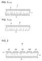
- Fig. 1 is a sectional view showing one example of the constitution of a thermal transfer sheet, as well as a thermal transfer image receptive sheet constituting the thermal transfer recording material of the present invention.
- Fig. 1 (a) is a sectional view showing the representative constitution of the thermal transfer sheet according to the present invention.
- Thermal transfer sheet 1 comprises dye layer 3 on one side of substrate sheet 2 and a heat resistant slipping layer 4 on the other side of substrate sheet 2.
- Fig. 1 (b) is a sectional view showing the representative constitution of a thermal transfer image receptive layer according to the present invention, and thermal transfer image receptive sheet 11 comprises dye receptive layer 13 on one side of substrate sheet 12.
- thermal transfer sheet according to the present invention will be described.
- substrate sheets employed in the thermal transfer sheet according to the present invention may be any of those known in the art.
- Listed as specific examples of preferred substrate sheets are thin paper such as glassine paper, condenser paper, or paraffin paper, oriented or non-oriented film composed of plastics such as high heat resistant polyester esters such as polyethylene terephthalate, polyethylene naphthalate, polybutylene terephthalate, polyphenylene sulfide, polyether ketone, or polyether sulfone, polypropylene, fluororesins, polycarbonate, cellulose acetate, polyethylene derivatives, polyvinyl chloride, polyvinylidene chloride, polystyrene, polyamide, polyimide, polymethylpentane, or ionomers, and those prepared by laminating these materials.
- the thickness of substrate sheets may be determined depending on materials to result in desired strength and heat resistance, but those of a thickness of about 1 - 100 ⁇ m are preferably employed.
- the dye layer constituting the thermal transfer sheet according to the present invention is a thermally sublimable colorant layer containing at least a dye and a binder resin.
- employed as dyes used in the thermally sublimable colorant layer may be those of a melting point of a maximum of 130 °C and preferably at most 70 °C. Further, the heat of fusion of at least one of the dyes is preferably at a maximum of 110 J/g.
- Dyes employable in the dye layer according to the present invention, may be used individually or in combinations of a plurality of dyes.
- employed in the dye layer is to be at least one dye which satisfies the aforesaid conditions of the present invention.
- thermal transfer recording materials may be employed without any limitation as long as the melting point of dyes is at most 130 °C. Of these, preferred are thermally diffusible dyes capable of forming chelates.
- Thermal diffusible dyes capable of forming chelates are not particularly limited as long as thermal transfer is possible.
- Various suitable types of prior art compounds may be selected and subsequently employed.
- chelate cyan dyes may be, for example, the compounds represented by General Formula (1) below.
- R 11 and R 12 each represent a substituted or unsubstituted aliphatic group and R 11 and R 12 may be the same or different.
- aliphatic groups are, for example, an alkyl group, a cycloalkyl group, an alkenyl group, and an alkynyl group.
- alkyl groups may, for example, be a methyl group, an ethyl group, a propyl group, and an i-propyl group.
- groups capable of being substituted to these alkyl groups are a straight or branched alkyl group (e.g., a methyl group, an ethyl group, an i-propyl group, a t-butyl group, an n-dodecyl group, and a 1-hexylnonyl group); a cycloalkyl group (e.g., a cyclopropyl group, a cyclohexyl group, and a bicyclo[2.2.1]heptyl group, and an adamantly group), and an alkenyl group (e.g., a 2-propylene group, and a oleyl group); an aryl group (e.g., a phenyl group, an ortho-tolyl group, an ortho-anisyl group, a 1-naphthyl group, and a 9-anthranyl group); a heterocyclic group (e.g., a
- Examples of the cycloalkyl group and the alkenyl group include those which are the same as the aforesaid substituents. Further, listed as examples of the alkynyl group are 1-propyne, 2-butyne, and 1-hexyne.
- R 11 and R 12 are groups which form a nonaromatic ring structure (for example, a pyrrolidine ring, a piperidine ring and a morpholine ring).
- R 13 is preferably an alkyl group, a cycloalkyl group, an alkoxy group, or an acylamino group, while n represents an integer of 0 - 4. When n is at least 2, a plurality of R 13 may be the same or different.
- R 14 is an alkyl group, examples of which include a methyl group, an ethyl group, an i-propyl group, a t-butyl group, an n-dodecyl group, and a 1-hexylnonyl group.
- R 14 is preferably a secondary or tertiary alkyl group and examples of preferred secondary or tertiary groups include an isopropyl group, a sec-butyl group, a tert-butyl group, and a 3-heptyl group.
- the most preferred substituents as R 14 include an isopropyl group as well as a tert-butyl group.
- the alkyl group of R 14 may be substituted. However, all R 14 are substituted with a substituent consisting of carbon atoms and hydrogen atoms are not substituted with a substituent containing other atoms.
- R 15 is an alkyl group, examples of which include an n-propyl group, an i-propyl group, a t-butyl group, an n-dodecyl group, and a 1-hexylnonyl group.
- R 15 is preferably a secondary or tertary alkyl group, and examples of preferred secondary or tertiary groups include an isopropyl group, a sec-butyl group, a tert-butyl group, and a 3-heptyl group.
- the most preferred substituents as R 15 are an isopropyl group and a tert-butyl group.
- the alkyl group of R 15 may be substituted. However, the aforesaid alkyl group is substituted with a substituent consisting only of carbon atoms and hydrogen atoms, and is not substituted with a substituent containing other atoms.
- R 16 represents an alkyl group, examples of which include an n-propyl group, an n-butyl group, an n-pentyl group, an n-hexyl group, an n-heptyl group, an isopropyl group, a sec-butyl group, a tert-butyl group, and a 3-heptyl group.
- Particularly preferred substituents as R 16 are straight chain alkyl groups having at least 3 carbon atoms, examples of which include an n-propyl group, an n-butyl group, an n-pentyl group, an n-hexyl group, and an n-heptyl group.
- the most preferred groups are an n-propyl group and an n-butyl group.
- the alkyl group represented by R 16 may be substituted.
- the aforesaid alkyl group is substituted with a substituent consisting only of carbon atoms and hydrogen atoms, and is never substituted with a substituent containing other atoms.
- chelate yellow dyes may be the compounds represented by General Formula (2) below.
- each of the substituents represented by R 1 and R 2 is, for example, a halogen atom, an alkyl group (an alkyl group having 1 - 12 carbon atoms which may be substituted with a substituent via an oxygen atom, a nitrogen atom, a sulfur atom or a carbonyl group, or may be substituted with an aryl group, an alkenyl group, an alkynyl group, a hydroxyl group, an amino group a nitro group, a carboxyl group, a cyano group, or a halogen atom, such as a methyl, isopropyl, t-butyl, trifluoromethyl, methoxymethyl, 2-methanesulfonylethyl, 2-methanesulfonamidoethyl, or cyclohexyl group), an aryl group (e.g., a phenyl, 4-t-butylphenyl, 3-
- alkyl groups and aryl groups represented by R 3 may be those which are the same as the alkyl groups and aryl groups represented by R 1 and R 2 .
- 5- to 6-membered aromatic rings which are constituted together with two carbon atoms represented by Z 1 may be rings such as be benzene, pyridine, pyrimidine, triazine, pyrazine, pyridazine, pyrrole, furan, thiophene, pyrazole, imidazole, triazole, oxazole, or thiazole. These rings may form condensed rings together with other aromatic rings. Further, substituents may be positioned on these rings and listed as the above substituents may be those which are the same as ones represented by R 1 and R 2 .
- chelate magenta dyes may be the compounds represented by General Formula (3) below.
- X represents a group or a group of atoms capable of forming a bidentate chelate
- Y represents a 5- or 6-membered aromatic hydrocarbon ring or a group of atoms forming a heterocyclic ring
- R 1 and R 2 each represent a hydrogen atom or a univalent substituent.
- n represents 0, 1, or 2.
- Z 2 represents a group of atoms which is necessary for forming an aromatic nitrogen-containing heterocyclic ring substituted with a group containing at least one nitrogen atom capable of being subjected to chelation.
- rings such as pyridine, pyrimidine, thiazole, or imidazole. These rings may further form a condensed ring with another carbon ring (such as a benzene ring) or a heterocyclic ring (such as a pyridine ring).
- Y represents a group of atoms which forms a 5- or 6-membered aromatic hydrocarbon ring or a heterocyclic ring, and may further have a substituent on the aforesaid ring or a condensed ring.
- aforesaid rings are a 3H-pyrrole ring, an oxazole ring, an imidazole ring, a thiazole ring, a 3H-pyrrolizine ring, an oxazolidine ring, an imidazolidine ring, a thiazolidine ring, a 3H-indole ring, a benzoxazole ring, a benzimidazole ring, a benzothiazole ring, a quinoline ring, and a pyridine ring.
- These rings may further form a condensed ring with another carbon ring (e.g., a benzene ring) and a heterocyclic ring (e.g., a pyridine ring).
- a condensed ring with another carbon ring e.g., a benzene ring
- a heterocyclic ring e.g., a pyridine ring
- Substituents on the ring include an alkyl group, an aryl group, a heterocyclic group, an acyl group, an amino group, a nitro group, a cyano group, an acylamino group, an alkoxy group, a hydroxy group, an alkoxycarbonyl group, and a halogen, and these groups may further be substituted.
- R 1 and R 2 each represent a hydrogen atom, a halogen atom, (e.g., a fluorine atom, and a chlorine atom), or a univalent substituent.
- a halogen atom e.g., a fluorine atom, and a chlorine atom
- a univalent substituent are, for example, an alkyl group, an alkoxy group, a cyano group, an alkoxycarbonyl group, an aryl group, a heterocyclic group, a carbamoyl group, a hydroxy group, an acyl group, and an acylamino group.
- X represents a group or a group of atoms capable of forming at least a bidentate chelate. Any X may be used as long as it is possible to form dyes as General Formula (3).
- X may be used as long as it is possible to form dyes as General Formula (3).
- 5-pyrazolone imidazole, pyrazole, pyrazolopyrrole, pyrazolopyrazole, pyrazoloimidazole, pyrazolotriazole, pyrazolotetrazole, barbituric acid, thiobarbituric acid, rhodanine, hydantoin, thiohydantoin, oxazolone, isooxazolone, indandione, pyrazolidinedione, oxazolidinedione, hydroxypyridone, or pyrazolopyridone.
- the dye layer according to the present invention incorporates binder resins with the above dyes.
- binders used in the dye layer are those which are employed in thermal transfer sheets for conventional heat-sensitive sublimation transfer system.
- binders may, for example, be cellulose based, polyacrylic acid based, polyvinyl alcohol based, and polyvinylpyrrolidone based water-soluble polymers, as well as organic solvent-soluble polymers such as acryl resins, methacryl resins, polystyrene, polycarbonate, polysulfone, polyester sulfone, polyvinyl butyral, polyvinyl acetal, ethylcellulose, and nitrocellulose. Of these, preferred are polyvinyl butyral, polyvinyl acetal, or cellulose based resins.
- the content of dyes and binder resins in the dye layer is not particularly limited. It is preferable that in view of performance, the above content is suitably determined.
- one of the features is that a binder is used which has a glass transition temperature (Tg 1 ) which differs in at least 0 °C from the melting point (MP 1 ) of the above dye.
- difference (Tg 1 - MP 1 ) between the glass transition temperature (Tg1) of the major binder constituting binder resins, and the melting point (MP 1 ) of the dye is at least 0 °C.
- the above difference is preferably at least 15 °C, is more preferably at least 30 °C, and is still more preferably 30 - 200 °C.
- incorporated in the dye layer according to the present invention may be various prior art additives other than the dyes and binder resins described above. It is possible to form a dye layer in such a manner that a liquid ink coating composition, prepared by dissolving or dispersing the above dyes and binder resins, and other additives in suitable solvents, is applied onto a substrate sheet employing a prior art means, such as a gravure coating method, and subsequently dried. It is possible to set the thickness of the dye layer according to the present invention commonly at about 0.1 - about 3.0 ⁇ m and preferably at 0.3 - 1.5 ⁇ m.
- thermally transferable protective layer is provided.
- the above thermally transferable protective layer is composed of a transparent resinous layer which is converted to a protective layer covering, via thermal transfer, the surface of images which are formed on an image receptive layer.
- Exemplified as protective layer forming resins may be polyester resins, polystyrene resins, acryl resins, polyurethane resins, acryl urethane resins, polycarbonate resins, epoxy-modified resins of each of these resins, silicone-modified resins of each of these resins, and mixtures thereof, as well as ionizing radiation curing resins and ultraviolet screening resins.
- Listed as preferred resins are polyester resins, polycarbonate resins, epoxy-modified resins, and ionizing radiation curing resins.
- polyester resins are alicyclic polyester resins comprised of alicyclic compounds comprising at least a diol component and an acid component.
- Preferred as polycarbonate resins are aromatic polycarbonate resins. Of these, aromatic polycarbonate resins described in JP-A No. 11-151867 are particularly preferred.
- epoxy-modified modified resins employed in the present inventions are epoxy-modified urethane, epoxy-modified polyethylene, epoxy-modified polyethylene terephthalate, epoxy-modified polyphenyl sulfite, epoxy-modified cellulose, epoxy-modified polypropylene, epoxy-modified polyvinyl chloride, epoxy-modified polycarbonate, epoxy-modified acryl, epoxy-modified styrene, epoxy-modified polymethyl methacrylate, epoxy-modified silicone, copolymers of epoxy-modified polystyrene and epoxy-modified polymethyl methacrylate, copolymers of epoxy-modified acryl and epoxy-modified polystyrene, as well as copolymers of epoxy-modified acryl and epoxy-modified silicone.
- epoxy-modified acryl epoxy-modified polystyrene, epoxy-modified polymethyl methacrylate, and epoxy-modified silicone
- copolymers of epoxy-modified polystyrene and epoxy-modified polymethyl methacrylate copolymers of epoxy-modified acryl and epoxy-modified polystyrene
- copolymers of epoxy-modified acryl and epoxy-modified silicone copolymers of epoxy-modified acryl and epoxy-modified silicone.
- ionizing radiation curing resins as a thermal transferable protective layer. Their incorporation in the thermal transferable protective layer results in excellent plasticizer resistance and abrasion resistance.
- ionizing radiation curing resins may be any of those known in the art.
- employed may be those prepared in such a manner that radically polymerizable polymers or oligomers are subjected to crosslinking and curing by exposure to ionizing radiation and if desired, are subjected to polymerization crosslinking employing electron beams and ultraviolet radiation in the presence of photopolymerization initiators.
- the main purpose of the protective layer containing ultraviolet screening resins is to provide printed matter with lightfastness.
- ultraviolet screening resins it is possible to use, for example, resins which are prepared in such a manner that reactive ultraviolet absorbing agents are allowed to react with, and bond to, thermoplastic resins or the above ionizing radiation curing resins.
- a reactive group such as ones having an addition-polymerizable double bond (for example, a vinyl group, an acryloyl group, and a metha-acryloyl group) or an alcoholic hydroxyl group, an amino group, a carboxyl group, an epoxy group, or isocyanate group
- an unreactive organic ultraviolet absorbing agents such as salicylate based, benzophenone based, benzotriazole based, substituted acrylonitrile based, nickel chelate based, hindered amine based ones which are conventionally known in the art.
- the main protective layer arranged in the thermal transferable protective layer, in a singly layer or multilayer structure, as described above, is formed to result in a thickness of commonly about 0.5 - about 10 ⁇ m, even though it may vary depending on the types of protective layer forming resins.
- the thermal transferable protective layer of the present invention is provided on a substrate sheet via a non-transferable releasing layer.
- the non-transferable releasing layer achieves an adhesion force between the substrate sheet and the non-transferable releasing layer which is higher than the adhesion force between the non-transferable releasing layer and the thermally transferable protective lawyer, and also achieves a higher adhesion force between the non-transferable releasing layer and the thermally transferable protective layer after applying heat than that prior to applying heat
- minute inorganic particles of an average diameter of at most 40 nm are incorporated in an amount of 30 - 80 percent by weight together with resinous binders;
- alkyl vinyl ether-maleic anhydride copolymers or derivatives thereof are incorporated in a total amount of at least 20 percent by weight; or (3) ionomers are incorporated in an amount of at least 20 percent by weight.
- other additives may be incorporated in the non-transferable releasing layer.
- inorganic micro-particles may, for example, be silica micro-particles such as colloidal silica, as well as particles of metal oxides such as tin oxide, zinc oxide, or zinc antimonate. It is preferable that the diameter of the inorganic micro-particles is condoled to be at most 40 nm. When the diameter exceeds 40 nm, surface unevenness of the thermally transferable protective layer increases due to the surface unevenness of the releasing layer. As a result, the transparency of the protective layer is unacceptably degraded.
- Resinous binders which are blended with inorganic micro-particles are not particularly limited, and it is possible to use any resins which are mixable. Examples include polyvinyl alcohol resins (PVA) of various degrees of saponification, polyvinyl acetal resins, polyvinyl butyral resins, acryl based resins, polyamide based resins, cellulose acetate, alkylcellulose, carboxymethylcellulose, and hydroxyalkylcellulose based resins, as well as polyvinylpyrrolidone resins.
- PVA polyvinyl alcohol resins
- the blending ratio (inorganic micro-particles/other blending components) of the inorganic micro-particles to the other blending components, comprising resinous binders as a main component is controlled to be in the range of 30/70 - 80/20 as a weight ratio.
- the blending ratio is less than 30/70, desired effects of the inorganic micro-particles become insufficient.
- the ratio exceeds 80/20, the resultant releasing layer results in an incomplete layer, whereby portions are formed wherein the substrate sheet and the protective layer are brought into direct contact.
- alkyl vinyl ether-maleic anhydride copolymers or derivatives thereof may, for example, be those in which an alkyl group in the alkyl vinyl ether portion is either a methyl group or an ethyl group, and in which the maleic anhydride portion results in a half ester, partially or completely, with alcohol (e.g., methanol, ethanol, propanol, isopropanol, butanol, and isobutanol).
- alcohol e.g., methanol, ethanol, propanol, isopropanol, butanol, and isobutanol.
- the releasing layer may be formed by employing only alkyl vinyl ether-maleic anhydride copolymers and derivatives thereof or mixtures thereof.
- other resins or micro-particles may be further added.
- alkyl vinyl ether-maleic anhydride copolymers and derivatives thereof, as well as mixtures thereof may be incorporated in an amount of at least 20 percent by weight. When the content is less than 20 percent by weight, it is not possible to result in sufficient desired effects of the alkyl vinyl ether-maleic anhydride copolymers and derivatives thereof.
- Resins or micro-particles which are blended with the alkyl vinyl ether-maleic anhydride copolymers or derivatives thereof are not particularly limited, and any of them may be employed as long as they are mixable and result in desired layer transparency during layer formation.
- resinous binders which are mixable with the aforesaid inorganic micro-particles, and resinous binders which are mixable with inorganic micro-particles.
- ionomers may, for example, be Surlyn A (manufactured by DuPont Co.) and the Chemipearl Series (manufactured by Mitusi Petrochemicals Co., Ltd.). Further, added to ionomers are, for example, the aforesaid inorganic micro-particles, resinous binders mixable with inorganic micro-particles, or other resins and micro-particles.
- the non-transferable releasing layer is formed in such a manner that a liquid coating composition containing any of the aforesaid components (1), (2), and (3) at the specified blending ratio is prepared; the resultant liquid coating composition is applied onto a substrate sheet employing a prior art technique such as a gravure coating method or a gravure reverse coating method; and the resultant coating is dried.
- the thickness of the non-transferable releasing layer after drying is commonly set at about 0.1 - about 2 ⁇ m.
- a thermally transferable protective layer applied onto a substrate sheet, via or not via the non-transferable releasing layer may be in a multilayer or a single layer structure.
- the multilayer structure other than the main protective layer which provides various types of durability to images, provided may be an adhesion layer arranged on the outermost surface of the thermally transferable protective layer to enhance adhesion between the thermally transferable protective layer and the image surface of printed matter, an auxiliary protective layer, and a layer (for example, an anti-counterfeiting layer and a hologram layer) which is used to add functions other than original one of the protective layer.
- the sequence of the main protective layer and other layers are somewhat optional. However, other layers are commonly arranged between the adhesion layer and the main protective layer so that, after the transfer, the main protective layer becomes the outermost surface of the image receiving surface.
- An adhesion layer may be formed on the outermost surface of the thermally transferable protective layer. It is possible to form the adhesion layer employing resins such as acryl resins, vinyl chloride based resins, vinyl acetate based resins, vinyl chloride/vinyl acetate copolymer resins, polyester resins, or polyamide resins, which exhibit desired adhesion during an adhesion under heating. Further in addition to the above resins, if desired, ionizing radiation curing resins and ultraviolet screening resins, described above, may be blended. The thickness of the adhesion layer is commonly set at 0.5 - 5 ⁇ m.
- the thermally transferable protective layer is formed on a non-transferable releasing layer or a substrate sheet in such a manner that, for example, a liquid protective layer coating composition containing protective layer forming resins, an adhesion layer liquid coating composition containing thermally fusible resins, and if desired, liquid coating compositions, to form additional layers, are previously prepared and those liquid coating compositions are then applied onto the non-transferable releasing layer or the substrate sheet in a predetermined order and subsequently dried.
- a liquid protective layer coating composition containing protective layer forming resins an adhesion layer liquid coating composition containing thermally fusible resins, and if desired, liquid coating compositions, to form additional layers
- a primer layer may be arranged between each of the layers.
- UV absorbers are incorporated in at least one of the thermally transferable protective layers.
- the resulting transparent ruinous layer is positioned as the surface of printed matter after transferring the protective layer.
- effects of UV absorbers decrease due to ambient influence over an extended period of time. Consequently, it is particularly preferable to incorporate UV absorbers in a heat-sensitive adhesive layer.
- UV absorbers are salicylic acid based, benzophenone based, benzotriazole based, and cyanoacrylate based UV absorbers. Specifically, these are commercially available under trade names such as Tinuvin P, Tinuvin 234, Tinuvin 320, Tinuvin 326, Tinuvin 327, Tinuvin 328, Tinuvin 312, and Tinuvin 315 (all manufactured by Ciba-Geigy Corp.); Sumisorb-110, Sumisorb-130, Sumisorb-140, Sumisorb-200, Sumisorb-250, Sumisorb-300, Sumisorb-320, Sumisorb-340, Sumisorb-350, and Sumisorb-400 (all manufactured by Sumitomo Chemical Co., Ltd.); and Mark LA-32, Mark LA-36, and Mark 1413 (all manufactured by Adeka Argus Chemical Co., Ltd.). It is possible to use any of these in the present invention.
- random copolymers of a Tg of at least 60 °C and preferably at least 80 °C which are prepared by random polymerization of reactive UV absorbers with acryl based monomers.
- UV absorbers may be those prepared by introducing groups having an addition-polymerizable double bond, such as a vinyl group, an acryloyl group, or a methacryloyl group, or other groups such as an alcohol based hydroxyl group, an amino group, a carboxyl group, an epoxy group, or an isocyanate group into prior art non-reactive UV absorbers such as a salicylate based, benzophenone based, benzotriazole based, substituted acrylonitrile based, nickel chelate based UV absorbers, and hindered amine based UV absorbers.
- these are commercially available under the trade names such as UVA635L and UVA633L (all manufactured by BASF Japan Co., Ltd.) and PUVA-30M (manufactured by Otsuka Chemical Co., Ltd.).
- the amount of reactive UV absorbers in the above acryl based random copolymers is commonly in the range of 10 - 90 percent by weight, and is preferably in the range of 30 - 70 percent by weight. Further, the molecular weight of such random copolymers may be set commonly at about 5,000 - about 250,000, and preferably at about 9,000 - about 30,000.
- the aforesaid UV absorbers and random copolymers of reactive UV absorbers with acryl based monomers may be incorporated individually or in combinations of both.
- the random copolymers of reactive UV absorbers with acyl based monomers are preferably incorporated in an amount ranging from 5 to 50 percent by weight with respect to the incorporated layer.
- UV absorbers other than UV absorbers, other light resistant agents may be incorporated.
- light resistant agents refer to chemical agents which minimize modification and decomposition of dyes by absorbing or shielding actions such as radiation energy, heat energy or oxidation which modify or decompose dyes.
- examples include antioxidants, conventionally known as additives for synthetic resins, and light stabilizers. When added, these may be incorporated in at least one thermally transferable protective lawyer, namely in at least one of the aforesaid peeling layer, the transparent resinous layer, or the heat-sensitive adhesion layer, and particularly preferably in the heat-sensitive adhesion layer.
- antioxidants are phenol based, monophenol based, bisphenol based or amine based primary antioxidants, as well as sulfur based or phosphorus based secondary antioxidants. Further listed as light stabilizers are hindered amine based ones.
- the used amount of the above-mentioned light resistant agents is not particularly limited, and is preferably 0.05 - 10 parts by weight with respect to 100 parts by weight of resins to form a layer in which the aforesaid agents are incorporated, but more preferably 3 - 10 parts by weight.
- the used amount is excessively small, it is difficult to achieve the desired effects of the light resistant agents, while an excessive amount is not cost effective.
- the transparent resinous layer of the protective layer transfer sheet may be arranged individually on a substrate sheet or following the ink layer of a thermal transfer sheet.
- a heat resistant slipping layer is arranged on the side opposite the dye layer across the substrate sheet.
- the aforesaid heat resistant slipping layer is arranged for the purpose of minimizing adhesion of heating devices such as a thermal head with a substrate sheet to achieve smooth production runs and eliminate deposits on thermal heads.
- resins in the aforesaid heat resistant slipping layer are, for example, natural or synthetic resins including cellulose based resins such as ethylcellulose, hydroxycellulose, hydroxypropylcellulose, methylcellulose, cellulose acetate, cellulose acetate butyrate, or nitrocellulose, vinyl based resins such as polyvinyl alcohol, polyvinyl acetate, polyvinyl butyral, polyvinyl acetal, or polyvinylpyrrolidone, acryl based resins such as methyl polymethacrylate, ethyl polymethacrylate, polyacryl amide, acrylonitrile-styrene copolymers, polyimide resins, polyamide resins, polyamidoimide resins, polyvinyl toluene resins, coumarone indene resins, polyester based resins, polyurethane resins, and silicone-modified or fluorine-modified urethane.
- cellulose based resins such as
- resins having a hydroxyl group based reactive group are employed and a crosslinked resinous layer is formed by simultaneously employing polyisocyanate as a crosslinking agent.
- releasing agents or slipping agents may, for example, be various waxes such as polyethylene wax or paraffin wax, higher aliphatic alcohol, organopolysiloxane, anionic surface active agents, cationic surface active agents, amphoteric surface active agents, nonionic surface active agents, fluorine based surface active agents, metal soaps, organic carboxylic acids and derivatives thereof, fluororesins, silicone resins, and inorganic micro-particles such as talc or silica.
- waxes such as polyethylene wax or paraffin wax, higher aliphatic alcohol, organopolysiloxane, anionic surface active agents, cationic surface active agents, amphoteric surface active agents, nonionic surface active agents, fluorine based surface active agents, metal soaps, organic carboxylic acids and derivatives thereof, fluororesins, silicone resins, and inorganic micro-particles such as talc or silica.
- the amount of slipping agents incorporated in the heat resistant slipping layer is commonly 5 - 50 percent by weight, and is preferably 10 - 30 percent by weight. It is possible to set the thickness of such a heat resistant slipping layer at about 0.1 - 10 ⁇ m and preferably at 0.3 - 5 ⁇ m.
- thermal transfer image receptive layer comprised of at least a substrate sheet and a dye receptive layer according to the present invention will now be described.
- a substrate sheet employed for the thermal transfer image receptive sheet functions to hold a dye receptive layer.
- the sheet since heat is applied to the sheet during thermal transfer, it is preferable that the sheet exhibits mechanical strength under high heat to prevent handling problems.
- Materials for such a substrate are not particularly limited. Listed as such materials are, for example, condenser paper, glassine paper, parchment paper, paper with a high degree of sizing, synthetic paper (either polyolefin based or polystyrene based), woodfree paper, art paper, coated paper, cast coated paper, wallpaper, lining paper, synthetic resin or emulsion impregnated paper, synthetic rubber latex impregnated paper, synthetic resin internally added paper, paper board, cellulose fiber paper, as well as films comprised of polyester, polyacrylate, polycarbonate, polyurethane, polyimide, polyetherimide, cellulose derivatives, polyethylene, ethylene-vinyl acetate copolymers, polypropylene, polystyrene, polyvinyl chloride, polyvinylidene chloride, polyvinyl alcohol, polyvinyl butyral, nylon, polyether ketone, polysulfone, polyethersulfone, tetrafluoroethylene, perfluoroal
- a laminated body composed of the above components in optional combinations.
- Listed as examples of representative laminated bodies are combinations of cellulose fiber paper and synthetic paper as well as cellulose synthetic paper and plastic film.
- the thickness of these component sheets is not limited but is commonly about 10 - about 300 ⁇ m.
- a layer comprising minute voids is provided.
- plastic film and synthetic paper provided with minute voids in the interior are plastic film and synthetic paper provided with minute voids in the interior.
- a layer provided with minute voids employing various types of coating systems.
- plastic film or synthetic paper provided with minute voids are those which are prepared in such a manner that polyolefin, particularly polypropylene as a main component, inorganic pigments and/or polypropylene, and incompatible polymers are blended and these are employed as a void formation initiating agent and the resultant mixture is oriented and casted into film.
- the resultant cushioning properties as well as heat insulating properties are inferior to ones in which polypropylene is used as a main component, due to the viscoelastic and thermal properties, whereby photographic printing speed is degraded and uneven density tends to result.
- the elastic modulus of plastic film and synthetic paper is preferably 5 x 10 8 - 1 x 10 10 Pa at 20 °C. Further, these plastic films and synthetic papers are commonly formed through biaxial orientation, and consequently heat results in shrinkage. When these are allowed to stand at 110 °C for 60 seconds, the degree of shrinkage is customarily 0.5 - 2.5 percent.
- the above plastic films or synthetic papers may be composed of a single layer or a plurality of layers. When composed of a plurality of layers, all the layers may contain voids or there may be layer(S) containing no voids. If desired, white pigments as a shielding agent may be blended into the above plastic films and synthetic papers. Further, for an increase in whiteness, additives such as optical brightening agents may be incorporated. It is preferable that the thickness of the minute void containing layer is 30 - 80 ⁇ m.
- plastic resins such as polyester, urethane resins, polycarbonate, acryl resins, polyvinyl chloride, or polyvinyl acetate. These may be employed individually or in combinations of a plurality of types.
- a layer composed of resins such as polyvinyl alcohol, polyvinylidene chloride, polyethylene, polypropylene, modified polyolefin, polyethylene terephthalate, or polycarbonate and synthetic paper.
- resins such as polyvinyl alcohol, polyvinylidene chloride, polyethylene, polypropylene, modified polyolefin, polyethylene terephthalate, or polycarbonate and synthetic paper.
- lamination methods may be, prior art lamination methods such as dry lamination, non-solvent (hot melt) lamination, or EC lamination. Of these, a dry lamination method as well as a non-solvent lamination method is preferred.
- suitable adhesives for the non-solvent lamination method are, for example, Takenate 720L, manufactured by Takeda Chemical Industries, Ltd., while listed as suitable adhesives for the dry lamination are, for example, Takeluck A969/Takenate A-5 (3/1), the Polysol PSA SE-1400 and Vinylol PSA AV-620 Series, manufactured by Showa Highpolymer Co., Ltd.
- the amount of these adhesives used is about 1 - about 8 g/m 2 in terms of solids, and is preferably 2 - 6 g/m 2 .
- binder resins in the thermal transfer image receptive layer according to the present invention.
- binders which are readily colored with dyes.
- polyolefin resins such as polypropylene, halogenated resins such as polyvinyl chloride or polyvinylidene chloride, vinyl based resins such as polyvinyl acetate or polyacrylic acid ester, polyester resins such as polyethylene terephthalate or polybutylene terephthalate, polystyrene resins, polyamide resins, phenoxy resins, copolymers of olefin such as ethylene or propylene with other vinyl based monomers, polyurethanes, polycarbonate, acryl resins, ionomers, compounds such as cellulose derivatives or mixtures thereof.
- polyester based resins vinyl based resins, and cellulose derivatives.
- thermal transfer recording materials of the present invention it is preferable to select binder resins employed in the thermal transfer image receptive sheet so that the difference (MP 1 - Tg 2 ) is from -30 to 30 degrees, wherein MP 1 is the melting point of at least one dye incorporated in the thermal transfer sheet previously described, and Tg 2 is the glass transition temperature of the aforesaid binder resin.
- releasing agents may be phosphoric acid ester based plasticizers, fluorine based compounds, and silicone oil (including reactive curing type silicones). Of these, silicone oil is preferred.
- silicone oil may be various types of modified silicone. Specific examples include amino-modified silicone, epoxy-modified silicone, alcohol-modified silicone, vinyl-modified silicone, and urethane-modified silicone. These may be blended and then applied, while they may undergo polymerization employing various reactions and then employed. Releasing agents may be employed individually or in combinations of at least two types.
- the added amount of releasing agents is preferably 0.5 - 30 parts by weight with respect to 100 parts by weight of dye receptive layer forming resins.
- these releasing agents may not be incorporated in the dye image receptive layer, but it may separately form a releasing layer on the dye receptive layer.
- metal ion containing compounds hereinafter also referred to as metal sources
- metal sources are inorganic and organic salts of metal ions and metal complexes. Of these, preferred are organic acid salts and complexes. Listed as metals are univalent and multivalent metals which belong to Groups I - VIII of the periodic table. Of these, preferred are Al, Co, Cr, Cu, Fe, Mg, Mn, Mo, Ni, Sn, Ti, and Zn, and Ni, Cu, Cr, Co, and Zn are particularly preferred.
- metal sources are salts of aliphatic compounds such as acetic acid or stearic acid with Ni 2+ , Cu 2+ , Cr 2+ , Co 2+ , or Zn 2+ , or salts of aromatic carboxylic acids such as benzoic acid or salicylic acid.
- M represents a metal ion, and preferably represents Ni 2+ , Cu 2+ , Cr 2+ , Co 2+ , or Zn 2+ .
- Q 1 , Q 2 , and Q 3 each represent a coordination compound capable of forming a coordination bond with a metal ion represented by M, and each may be the same or different among them. It is possible to select such coordination compounds from those, described, for example, in Kireto Kagaku (Chelate Science) (5), published by Nanko Do.
- L- represents an organic anion group, and specifically, it is possible list tetraphenylboron anions and an alkylbenzenesufonic acid anions.
- M 2+ represents a divalent transition metal ion.
- nickel and zinc are preferred.
- X 1 - represents a coordination compound capable of forming a complex with divalent metal ions. Further, these compounds may have neutral ligands in response to the central atom, and H 2 O and NH 3 are listed as representative ligands.
- an interlayer may be provided between the substrate sheet and the dye receptive layer.
- the term "interlayer” refers to all the layers between the substrate sheet and the dye receptive layer, and may be multilayered. Listed as functions of the interlayer are a solvent resistant function, a barrier function, an adhesion function, a whiteness providing function, a shielding function, and an antistatic function. However, the functions are not limited thereto, and it is possible to employ all appropriate conventional interlayers known in the art.
- water-soluble resins In order to provide an interlayer with solvent resistance as well as a barrier function, it is preferable to use water-soluble resins.
- cellulose based resins such as carboxymethyl cellulose
- polysaccharide based resins such as starch
- proteins such as casein, gelatin, or agar
- vinyl based resins such as polyvinyl alcohol, ethylene-vinyl acetate copolymers, polyvinyl acetate, vinyl chloride-vinyl acetate copolymers, vinyl acetate-(meth)acryl copolymers, (meth)acryl resins, styrene-(meth)acryl copolymers, styrene resins, and polyamide based resins such as melamine resins, urea resins, or benzoguanamine resins, polyester; and polyurethane.
- cellulose based resins such as carboxymethyl cellulose
- polysaccharide based resins such as starch
- proteins such as
- Watersoluble resins refer to resins which are completely dissolved (a particle diameter of at most 0.01 ⁇ m) in solvents comprised of water as a main component, or result in a state of colloidal dispersion (0.01 - 0.1 ⁇ m) or slurry (at least 1 ⁇ m).
- these water-soluble resins particularly preferred are those which are neither dissolved in nor swelled by alcohols such as methanol, ethanol, or isopropyl alcohol, or general purpose solvents such as hexane, cyclohexane, acetone, methyl ethyl ketone, xylene, ethyl acetate, butyl acetate, or toluene.
- resins are most preferred which are completely dissolved in solvents containing water as a main component.
- urethane resins and polyolefin based resins are commonly employed, though resins may differ depending on the type of substrates and surface treatments. Further, when thermoplastic resins having active hydrogen and curing agents such as isocyanate compounds are simultaneously employed, desired adhesion function is obtained.
- optical brightening agents Listed as usable optical brightening agents may be any of the conventional compounds known in the art.
- optical whitening agents are stilbene based, distilbene based, benzoxazole based, styryl-oxazole based, pyrene-oxazole based, coumarin based, aminocoumarin based, imidazole based, benzimidazole based, pyrazolone based, and distyryl-biphenyl based optical brightening agents. It is possible to control whiteness based on the type of these optical brightening agents and the added amount thereof. Optical brightening agents may be added employing any of appropriate methods.
- listed is a method in which they are dissolved in water and then added, a method in which they are crushed and dispersed employing a ball mill or a colloid mill and then added, a method in which they are dissolved in high boiling point organic solvents, mixed with a hydrophilic colloidal solution and then added in the form of oil-in-water type dispersion, or a method in which thy are impregnated in polymer latex and then added.
- titanium oxide may be incorporated in the interlayer.
- the use of titanium oxide is preferred since it provides a greater degree of freedom for selecting substrates.
- Titanium oxide includes two types, namely rutile type titanium oxide and anatase type titanium oxide. When whiteness and desired effects of optical brightening agents are considered, anatase type titanium oxide which exhibits absorption of the ultraviolet region at a shorter wavelength side than rutile type titanium oxide is preferred.
- dispersion may be performed by employing titanium oxide which is subjected to a hydrophilic surface treatment or conventional dispersing agents such as surface active agents or ethylene glycol.
- the amount of titanium oxide added is preferably 10 - 400 parts by weight in terms of solids with respect to 100 parts by weight of the resinous solids.
- electrically conductive inorganic fillers In order to provide an interlayer with an antistatic function, electrically conductive inorganic fillers, electrically conductive organic materials such as polyanilinesulfonic acid, and prior art electrically conductive materials may be selected and then used while matching with the binder resins of the interlayer.
- the thickness of such an interlayer is preferably set at about 0.1 - about 10 ⁇ m.
- Fig. 2 is a sectional view showing one example of an embodiment in which one surface of the thermal transfer sheet according to the present invention is successively supplied.
- Thermal transfer sheet 21 in Fig. 2 is provided with dye layers 23Y, 23M, and 23C corresponding to yellow (Y), magenta (M), and cyan (C) dyes on the same plane of a substrate sheet, and a thermally transferable protective layer or post-thermal treatment region 23OP in the face sequence.
- a small spacing is provided between dye layers.
- such spacing may appropriately be provided in response to the control method of the thermal transfer recording apparatus.
- the methods for providing such a mark are not particularly limited.
- the thermal transfer sheet is shown above in which each of the dye layers, and the thermally transferable protective layer or the region which performs the post-thermal treatment are provided on the same plane of the substrate sheet.
- dyes incorporated in the dye layer are compounds prior to reaction. As a result, strictly speaking, they may not be designated as Y, M, and C dyes.
- dye layers in terms of a layer which finally forms Y, M, and C images, for convenience, they are designated as dye layers.
- chelation is completed after dye transfer. Therefore, it is preferable that a thermal treatment is performed following the dye transfer.
- the reaction is completed by heating, employing thermal heads, to result in a uniform heat distribution, and at the same time, it is possible to form images of a desired gloss.
- the post-thermal treatment and the transfer of the thermally transferable protective layer may simultaneously be carried out.
- a heat resistant slipping layer liquid coating composition with the composition described below was applied onto the surface opposite the easy adhesion treated surface of a 6 ⁇ m thick polyethylene terephthalate film (K-203E-6F, manufactured by Diafoil Hoechst Co., Ltd.) which had been subjected to easy adhesion treatment on one side, employing a gravure coating method and then dried. Thereafter the resultant coating was subjected to a thermal curing treatment, whereby a thermal transfer substrate sheet having a heat resistant slipping layer of a dried layer thickness of 1 ⁇ m was prepared.
- K-203E-6F polyethylene terephthalate film
- Each of Dye Layer Liquid Coating Compositions 1 - 7, and 11 - 15 with the compositions described in Table 1 was applied (resulting in a dried solid weight of 0.7 g/m 2 ) onto the surface opposite the surface of the heat resistant slipping layer on polyethylene terephthalate film to form each of the dye layers, employing a wire bar coating method and subsequently dried at 100 °C for one minute, whereby Thermal Transfer Sheets 1 - 7, and 11 - 15 were prepared.
- the melting point of each of the dyes employed for preparing above Thermal Transfer Sheets 1 - 7, and 11 - 15, and heat of fusion determined by a DSC method are as follows.
- the interlayer liquid coating composition described below was applied onto one surface of 150 ⁇ m thick synthetic paper (UPO FPG-150, manufactured by Oji Yuka Goseishi Co., Ltd.), employing a wire bar coating system and subsequently dried at 120 °C for one minute, whereby a sublayer at a dried solid weight of 2.0 g/m 2 was formed.
- UPO FPG-150 manufactured by Oji Yuka Goseishi Co., Ltd.
- each of the dye receptive layer liquid coating compositions with the compositions described in Table 2 was applied onto the aforesaid sublayer to result in a dried solid weight of 4 g/m 2 , employing a wire bar coating system, and subsequently dried at 110 °C for 30 seconds, whereby Thermal Transfer Image Receptive Sheets 1 - 5 were obtained.
- Interlayer Liquid Coating Composition 35 percent aqueous acryl based emulsion (Nikasol A-O8, manufactured by Nippon Carbide Industries Co., Ltd.) solution 5.7 weight parts Pure water 94.0 weight parts
- each of the additives in the dye receptive layer liquid coating composition described in Table 2 is detailed as follows.
- the dye receptive layer portion of the thermal transfer image receptive sheet prepared as above and the dye layer of the thermal transfer sheet in combination listed in Table 3 were stacked and set in a thermal transfer apparatus fitted with a 300 dpi (hereinafter dpi represents the number of dots per 2.54 cm) line thermal head in which the resistor shape was rectangular (length in the primary scanning direction of 80 ⁇ m x length in the secondary scanning direction of 120 ⁇ m).
- dpi represents the number of dots per 2.54 cm
- Transmission density of the thermal transfer sheet after printing, which had been prepared as described above, was determined employing a densitometer (X-rite 310 Status A). Measurements were performed under three conditions of applied energy of 20 mJ/mm 2 , 40 mJ/mm 2 , and 60 mJ/mm 2 . Subsequently, a transfer ratio was calculated based on the formula below, referring to densities prior to and after printing. Transfer ratio ⁇ (transmission density prior to printing - transmission density after printing ⁇ /(transmission density prior to printing)) x 100 (in percent)
- optical reflection density (OD) of each of the printing samples prepared as above was determined employing Macbeth Reflection Densitometer (manufactured by Gretag Macbeth Corp.) and evaluated based on the criteria below. Evaluation Criteria
- Table 3 shows the results obtained as above.
Landscapes
- Physics & Mathematics (AREA)
- Optics & Photonics (AREA)
- Thermal Transfer Or Thermal Recording In General (AREA)
Applications Claiming Priority (2)
| Application Number | Priority Date | Filing Date | Title |
|---|---|---|---|
| JP2003332734 | 2003-09-25 | ||
| JP2003332734 | 2003-09-25 |
Publications (2)
| Publication Number | Publication Date |
|---|---|
| EP1518705A2 true EP1518705A2 (fr) | 2005-03-30 |
| EP1518705A3 EP1518705A3 (fr) | 2005-11-23 |
Family
ID=34191470
Family Applications (1)
| Application Number | Title | Priority Date | Filing Date |
|---|---|---|---|
| EP04255650A Withdrawn EP1518705A3 (fr) | 2003-09-25 | 2004-09-17 | Matériau d'enregistrement par transfert thermique |
Country Status (2)
| Country | Link |
|---|---|
| US (1) | US20050069656A1 (fr) |
| EP (1) | EP1518705A3 (fr) |
Families Citing this family (2)
| Publication number | Priority date | Publication date | Assignee | Title |
|---|---|---|---|---|
| EP1974948A3 (fr) * | 2007-03-29 | 2012-02-08 | FUJIFILM Corporation | Procédé de formation d'images utilisant un système de transfert thermosensible |
| EP3374450A1 (fr) * | 2016-03-04 | 2018-09-19 | Hp Indigo B.V. | Composition de toner électrostatique liquide de sécurité |
Citations (9)
| Publication number | Priority date | Publication date | Assignee | Title |
|---|---|---|---|---|
| JPS5978893A (ja) | 1982-10-29 | 1984-05-07 | Konishiroku Photo Ind Co Ltd | 感熱転写記録方法 |
| JPS59109340A (ja) | 1982-12-15 | 1984-06-25 | Mitsuboshi Belting Ltd | 繊維とゴム配合物との接着方法 |
| JPS59109349A (ja) | 1982-12-15 | 1984-06-25 | 松下電工株式会社 | 電気用積層板 |
| JPS602398A (ja) | 1983-06-21 | 1985-01-08 | Mitsubishi Chem Ind Ltd | 転写記録方法 |
| JPH0494974A (ja) | 1990-08-10 | 1992-03-27 | Konica Corp | 感熱転写記録材料および感熱転写記録方法 |
| JPH0497894A (ja) | 1990-08-14 | 1992-03-30 | Konica Corp | 感熱転写記録材料および感熱転写記録方法 |
| JPH0665511A (ja) | 1992-05-30 | 1994-03-08 | Basf Ag | ジアントラキノン−n,n’−ジヒドロアジン及びその塩素化生成物の製法 |
| JP2856225B2 (ja) | 1991-03-20 | 1999-02-10 | 自動車機器株式会社 | ブレーキ倍力装置 |
| JP2003220768A (ja) | 2002-01-31 | 2003-08-05 | Dainippon Printing Co Ltd | 熱転写記録材料 |
Family Cites Families (5)
| Publication number | Priority date | Publication date | Assignee | Title |
|---|---|---|---|---|
| US4756950A (en) * | 1985-03-23 | 1988-07-12 | Mitsubishi Paper Mills, Ltd. | Gradation recording heat-transfer sheet |
| US5391536A (en) * | 1993-07-08 | 1995-02-21 | Agfa-Gevaert N.V. | Oxalylamino substituted indoaniline dyes for use in thermal sublimation transfer printing |
| JPH08244363A (ja) * | 1995-03-10 | 1996-09-24 | Sony Corp | 熱転写記録材料 |
| US6235679B1 (en) * | 1998-01-28 | 2001-05-22 | Konica Corporation | Thermal transfer image recording method |
| WO2002072363A1 (fr) * | 2001-03-09 | 2002-09-19 | Dai Nippon Printing Co., Ltd. | Feuille de transfert thermique d'images |
-
2004
- 2004-09-15 US US10/941,329 patent/US20050069656A1/en not_active Abandoned
- 2004-09-17 EP EP04255650A patent/EP1518705A3/fr not_active Withdrawn
Patent Citations (9)
| Publication number | Priority date | Publication date | Assignee | Title |
|---|---|---|---|---|
| JPS5978893A (ja) | 1982-10-29 | 1984-05-07 | Konishiroku Photo Ind Co Ltd | 感熱転写記録方法 |
| JPS59109340A (ja) | 1982-12-15 | 1984-06-25 | Mitsuboshi Belting Ltd | 繊維とゴム配合物との接着方法 |
| JPS59109349A (ja) | 1982-12-15 | 1984-06-25 | 松下電工株式会社 | 電気用積層板 |
| JPS602398A (ja) | 1983-06-21 | 1985-01-08 | Mitsubishi Chem Ind Ltd | 転写記録方法 |
| JPH0494974A (ja) | 1990-08-10 | 1992-03-27 | Konica Corp | 感熱転写記録材料および感熱転写記録方法 |
| JPH0497894A (ja) | 1990-08-14 | 1992-03-30 | Konica Corp | 感熱転写記録材料および感熱転写記録方法 |
| JP2856225B2 (ja) | 1991-03-20 | 1999-02-10 | 自動車機器株式会社 | ブレーキ倍力装置 |
| JPH0665511A (ja) | 1992-05-30 | 1994-03-08 | Basf Ag | ジアントラキノン−n,n’−ジヒドロアジン及びその塩素化生成物の製法 |
| JP2003220768A (ja) | 2002-01-31 | 2003-08-05 | Dainippon Printing Co Ltd | 熱転写記録材料 |
Also Published As
| Publication number | Publication date |
|---|---|
| US20050069656A1 (en) | 2005-03-31 |
| EP1518705A3 (fr) | 2005-11-23 |
Similar Documents
| Publication | Publication Date | Title |
|---|---|---|
| JP4493403B2 (ja) | 熱転写受像シートとその製造方法 | |
| JP4493565B2 (ja) | 熱転写受像シート及びその製造方法 | |
| JP4992984B2 (ja) | 熱転写受像シート及びその製造方法 | |
| JP4544941B2 (ja) | 熱転写受像シート | |
| EP1520727B1 (fr) | Procédé d'obtention d'image utilisant un matériel de transfert thermique | |
| JP2005103799A (ja) | 保護層転写シートとそれを用いた画像形成方法 | |
| JP4703990B2 (ja) | 熱転写受像シート及びその製造方法 | |
| JP5057255B2 (ja) | 熱転写受像シートとその製造方法 | |
| EP1518705A2 (fr) | Matériau d'enregistrement par transfert thermique | |
| JP4493546B2 (ja) | 熱転写受像シート | |
| JP2006076052A (ja) | 熱転写受像シートとそれを用いた画像形成方法 | |
| JP2005119280A (ja) | 熱転写記録材料 | |
| JP2003094840A (ja) | 感熱転写記録材料及び感熱転写記録方法 | |
| JP2006043992A (ja) | かぶり低減方法および感熱転写記録用インクシート | |
| JP2005313359A (ja) | 熱転写インクシート及び画像形成方法 | |
| US20050233901A1 (en) | Thermal transfer recording material | |
| JP2008062549A (ja) | 熱転写受像シート | |
| JP2005335375A (ja) | 画像形成方法 | |
| JP2010188740A (ja) | 熱転写受像シート | |
| JP2010228456A (ja) | 熱転写受像シート | |
| JP2005313434A (ja) | 熱転写画像形成方法及び画像形成物 | |
| JP2005125755A (ja) | 画像形成方法 | |
| JP2005313357A (ja) | 熱転写インクシート及びそれを用いた画像形成方法 | |
| JP2005125754A (ja) | 画像形成物及びその画像形成方法 | |
| JP2005313358A (ja) | 熱転写型画像記録材料の製造方法、熱転写型画像記録材料及びそれを用いた画像形成方法 |
Legal Events
| Date | Code | Title | Description |
|---|---|---|---|
| PUAI | Public reference made under article 153(3) epc to a published international application that has entered the european phase |
Free format text: ORIGINAL CODE: 0009012 |
|
| AK | Designated contracting states |
Kind code of ref document: A2 Designated state(s): AT BE BG CH CY CZ DE DK EE ES FI FR GB GR HU IE IT LI LU MC NL PL PT RO SE SI SK TR |
|
| AX | Request for extension of the european patent |
Extension state: AL HR LT LV MK |
|
| PUAL | Search report despatched |
Free format text: ORIGINAL CODE: 0009013 |
|
| AK | Designated contracting states |
Kind code of ref document: A3 Designated state(s): AT BE BG CH CY CZ DE DK EE ES FI FR GB GR HU IE IT LI LU MC NL PL PT RO SE SI SK TR |
|
| AX | Request for extension of the european patent |
Extension state: AL HR LT LV MK |
|
| RIC1 | Information provided on ipc code assigned before grant |
Ipc: 7B 41M 5/03 A |
|
| 17P | Request for examination filed |
Effective date: 20060428 |
|
| AKX | Designation fees paid |
Designated state(s): DE FR GB |
|
| 17Q | First examination report despatched |
Effective date: 20060721 |
|
| STAA | Information on the status of an ep patent application or granted ep patent |
Free format text: STATUS: THE APPLICATION IS DEEMED TO BE WITHDRAWN |
|
| 18D | Application deemed to be withdrawn |
Effective date: 20061204 |