EP1518651A1 - Verfahren und vorrichtung zur herstellung von löchern in einer glasplatte - Google Patents
Verfahren und vorrichtung zur herstellung von löchern in einer glasplatte Download PDFInfo
- Publication number
- EP1518651A1 EP1518651A1 EP03733154A EP03733154A EP1518651A1 EP 1518651 A1 EP1518651 A1 EP 1518651A1 EP 03733154 A EP03733154 A EP 03733154A EP 03733154 A EP03733154 A EP 03733154A EP 1518651 A1 EP1518651 A1 EP 1518651A1
- Authority
- EP
- European Patent Office
- Prior art keywords
- glass plate
- chamfering
- recess
- forming
- drill
- Prior art date
- Legal status (The legal status is an assumption and is not a legal conclusion. Google has not performed a legal analysis and makes no representation as to the accuracy of the status listed.)
- Withdrawn
Links
Images



Classifications
-
- B—PERFORMING OPERATIONS; TRANSPORTING
- B23—MACHINE TOOLS; METAL-WORKING NOT OTHERWISE PROVIDED FOR
- B23B—TURNING; BORING
- B23B35/00—Methods for boring or drilling, or for working essentially requiring the use of boring or drilling machines; Use of auxiliary equipment in connection with such methods
- B23B35/005—Measures for preventing splittering
-
- B—PERFORMING OPERATIONS; TRANSPORTING
- B23—MACHINE TOOLS; METAL-WORKING NOT OTHERWISE PROVIDED FOR
- B23B—TURNING; BORING
- B23B39/00—General-purpose boring or drilling machines or devices; Sets of boring and/or drilling machines
- B23B39/16—Drilling machines with a plurality of working-spindles; Drilling automatons
- B23B39/22—Drilling machines with a plurality of working-spindles; Drilling automatons with working-spindles in opposite headstocks
-
- B—PERFORMING OPERATIONS; TRANSPORTING
- B24—GRINDING; POLISHING
- B24B—MACHINES, DEVICES, OR PROCESSES FOR GRINDING OR POLISHING; DRESSING OR CONDITIONING OF ABRADING SURFACES; FEEDING OF GRINDING, POLISHING, OR LAPPING AGENTS
- B24B19/00—Single-purpose machines or devices for particular grinding operations not covered by any other main group
- B24B19/006—Single-purpose machines or devices for particular grinding operations not covered by any other main group for grinding hollow glassware, bottles
-
- B—PERFORMING OPERATIONS; TRANSPORTING
- B24—GRINDING; POLISHING
- B24B—MACHINES, DEVICES, OR PROCESSES FOR GRINDING OR POLISHING; DRESSING OR CONDITIONING OF ABRADING SURFACES; FEEDING OF GRINDING, POLISHING, OR LAPPING AGENTS
- B24B9/00—Machines or devices designed for grinding edges or bevels on work or for removing burrs; Accessories therefor
- B24B9/02—Machines or devices designed for grinding edges or bevels on work or for removing burrs; Accessories therefor characterised by a special design with respect to properties of materials specific to articles to be ground
- B24B9/06—Machines or devices designed for grinding edges or bevels on work or for removing burrs; Accessories therefor characterised by a special design with respect to properties of materials specific to articles to be ground of non-metallic inorganic material, e.g. stone, ceramics, porcelain
- B24B9/08—Machines or devices designed for grinding edges or bevels on work or for removing burrs; Accessories therefor characterised by a special design with respect to properties of materials specific to articles to be ground of non-metallic inorganic material, e.g. stone, ceramics, porcelain of glass
-
- B—PERFORMING OPERATIONS; TRANSPORTING
- B65—CONVEYING; PACKING; STORING; HANDLING THIN OR FILAMENTARY MATERIAL
- B65G—TRANSPORT OR STORAGE DEVICES, e.g. CONVEYORS FOR LOADING OR TIPPING, SHOP CONVEYOR SYSTEMS OR PNEUMATIC TUBE CONVEYORS
- B65G49/00—Conveying systems characterised by their application for specified purposes not otherwise provided for
- B65G49/05—Conveying systems characterised by their application for specified purposes not otherwise provided for for fragile or damageable materials or articles
- B65G49/06—Conveying systems characterised by their application for specified purposes not otherwise provided for for fragile or damageable materials or articles for fragile sheets, e.g. glass
- B65G49/061—Lifting, gripping, or carrying means, for one or more sheets forming independent means of transport, e.g. suction cups, transport frames
-
- B—PERFORMING OPERATIONS; TRANSPORTING
- B65—CONVEYING; PACKING; STORING; HANDLING THIN OR FILAMENTARY MATERIAL
- B65G—TRANSPORT OR STORAGE DEVICES, e.g. CONVEYORS FOR LOADING OR TIPPING, SHOP CONVEYOR SYSTEMS OR PNEUMATIC TUBE CONVEYORS
- B65G2249/00—Aspects relating to conveying systems for the manufacture of fragile sheets
- B65G2249/04—Arrangements of vacuum systems or suction cups
-
- Y—GENERAL TAGGING OF NEW TECHNOLOGICAL DEVELOPMENTS; GENERAL TAGGING OF CROSS-SECTIONAL TECHNOLOGIES SPANNING OVER SEVERAL SECTIONS OF THE IPC; TECHNICAL SUBJECTS COVERED BY FORMER USPC CROSS-REFERENCE ART COLLECTIONS [XRACs] AND DIGESTS
- Y10—TECHNICAL SUBJECTS COVERED BY FORMER USPC
- Y10T—TECHNICAL SUBJECTS COVERED BY FORMER US CLASSIFICATION
- Y10T408/00—Cutting by use of rotating axially moving tool
- Y10T408/03—Processes
Definitions
- the present invention relates to a method and an apparatus for drilling a hole in a glass plate for forming a through hole in a glass plate for use in such as a window for an automobile and for chamfering the opening of the through hole.
- a recess is formed in an upper surface of the glass plate, and a recess communicating with that recess is formed in a lower surface of the glass plate. Then, edges of opening of each of the recesses formed in the upper and lower surfaces of the glass plate are provided with chamfering, generally light-chamfering, by using a chamfering drill.
- a recess is formed in the upper surface of the glass plate by one recess forming drill with a chamfering grinding wheel, and the edge of the opening of the recess is subsequently chamfered.
- a recess communicating with the recess in the upper surface of the glass plate is formed in the lower surface of the glass plate by using the other recess forming drill with a chamfering grinding wheel, and the edge of the opening of the recess in the lower surface of the glass plate is subsequently chamfered.
- the present invention has been devised in view of the above-described aspects, and its object is to provide a method and an apparatus for drilling a hole in a glass plate which make it possible to shorten the time expended in drilling a hole in the glass plate without making the program of the numerical controller complex, thereby making it possible to improve the throughput of drilled glass plates.
- a method of drilling a hole in a glass plate in accordance with a first aspect of the invention comprises: a recess forming step of forming in a recess forming section a recess in one surface of a glass plate and forming therein a recess communicating with the recess in another surface of the glass plate; a chamfering step of chamfering in a chamfering section edges of opening of each of the recesses formed in the one surface and the other surface of the glass plate; and a transporting step of transporting to the recess forming section the glass plate in which the recesses are to be formed and of transporting to the chamfering section the glass plate in which the recesses have been formed in the recess forming section, the recess forming step and the chamfering step being effected concurrently.
- the recesses are formed in the recess forming section, and chamfering is provided in the chamfering section. Therefore, the program of the controller for implementing this method can be simplified. Furthermore, since the recess forming step and the chamfering step are effected concurrently, it is possible to shorten the time expended in drilling a hole in the glass plate, thereby making it possible to improve the throughput of drilled glass plates.
- the recess forming step has a plurality of steps of forming pairs of recesses communicating with each other, and in the plurality of steps the formation of each of the pairs of recesses with respect to predetermined different portions of the glass plate is effected concurrently.
- the chamfering step has a step of chamfering the edge of the opening of the recess in the other surface of the glass plate in synchronism with the chamfering of the edge of the opening of the recess in the one surface of the glass plate.
- the edges of the openings can be chamfered speedily.
- the chamfering step has a step of chamfering the edge of the opening of the recess in the one surface of the glass plate, and after the chamfering, chamfering the edge of the opening of the recess in the other surface of the glass plate.
- An apparatus for drilling a hole in a glass plate in accordance with a first aspect of the invention comprises: recess forming means for forming in a recess forming section a recess in one surface of a glass plate and forming therein a recess communicating with the recess in another surface of the glass plate; chamfering means for chamfering in a chamfering section edges of opening of each of the recesses formed in the one surface and the other surface of the glass plate by the recess forming means; and transporting means for transporting to the recess forming section the glass plate in which the recesses are to be formed and for transporting to the chamfering section the glass plate in which the recesses have been formed by the recess forming means, the chamfering means being adapted to chamfer the edges of the opening of each of the recesses in the glass plate concurrently with the formation of the recesses in the glass plate by the recess forming means.
- the recesses are formed in the recess forming section, and chamfering is provided in the chamfering section. Therefore, the program of the controller for implementing this method can be simplified. Furthermore, since the recess forming step and the chamfering step are effected concurrently, it is possible to shorten the time expended in drilling a hole in the glass plate, thereby making it possible to improve the throughput of drilled glass plates.
- the recess forming means has a plurality of pairs of recess forming drills for forming pairs of recesses communicating with each other in the one surface and the other surface of the glass plate, and the plurality of recess forming drills are adapted to concurrently effect the formation of each of the pairs of recesses with respect to predetermined different portions of the glass plate.
- the recess forming means has recess-forming-drill vertically moving means for vertically moving the plurality of pairs of recess forming drills with respect to the glass plate, and the recess-forming-drill vertically moving means is adapted to raise and lower synchronously with each other the recess forming drills for forming the recesses in the one surface of the glass plate and to raise and lower synchronously with each other the recess forming drills for forming the recesses in the other surface of the glass plate.
- the recess forming means has recess-forming-drill moving means for moving each of the pairs of recess forming drills independently of each other in parallel to the surfaces of the glass plate.
- the chamfering means has one chamfering drill for chamfering the edge of the opening of the recess in the one surface of the glass plate and another chamfering drill for chamfering the edge of the opening of the recess in the other surface of the glass plate, disposed in such an manner as to oppose the one chamfering drill, and the chamfering means is adapted to effect the chamfering of the edge of the opening of the recess in the other surface of the glass plate by the other chamfering drill in synchronism with the chamfering of the edge of the opening of the recess in the one surface of the glass plate by the one chamfering drill.
- the chamfering means is adapted to effect the chamfering of the edge of the opening of the recess in the other surface of the glass plate by the other chamfering drill in synchronism with the chamfering of the edge of the opening of the recess in the one surface of the glass plate by the one chamfering drill. Therefore, the edges of the openings can be chamfered speedily.
- the chamfering means has one chamfering drill for chamfering the edge of the opening of the recess in the one surface of the glass plate and another chamfering drill for chamfering the edge of the opening of the recess in the other surface of the glass plate, disposed in such an manner as to oppose the one chamfering drill, and the chamfering means is adapted to effect the chamfering of the edge of the opening of the recess in the one surface of the glass plate by the one chamfering drill, and after that chamfering, to effect the chamfering of the edge of the opening in the other surface of the glass plate by the other chamfering drill.
- the chamfering means is adapted to effect the chamfering of the edge of the opening of the recess in the one surface of the glass plate by the one chamfering drill, and to effect the chamfering of the edge of the opening in the other surface of the glass plate by the other chamfering drill after that chamfering. Therefore, it is possible to avoid mutual interference in the chamfering operation and accurately chamfer the edges of the opening of each of the recesses in the glass plate.
- the chamfering means has chamfering-drill vertically moving means for vertically moving the one chamfering drill and the other chamfering drill independently of each other with respect to the glass plate.
- the chamfering means has chamfering-drill moving means for moving the one chamfering drill and the other chamfering drill synchronously with each other in parallel to the surfaces of the glass plate.
- chamfering is preferably light-chamfering, but the invention is not limited to the same.
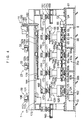
- an apparatus 1 for drilling a hole in a glass plate in accordance with this embodiment is comprised of the following: a recess forming means 8 for forming in a recess forming section 2 recesses 5 in an upper surface 4 of a glass plate 3 and recesses 6 communicating with the recesses 5 in a lower surface 7 of the glass plate 3, as shown in Fig.
- a chamfering means 10 for effecting in a chamfering section 9 adjacent to the recess forming section 2 the chamfering, in this embodiment light-chamfering, of edges 12 and 13 of the respective opening of each of the recesses 5 and 6 in the glass plate 3 where the recesses 5 and 6 have been formed by the recess forming means 8; a transporting means 11 for consecutively transporting to the recess forming section 2 the glass plates 3 in which the recesses 5 and 6 are to be formed, and for consecutively transporting to the chamfering section 9 the glass plates 3 in which the recesses 5 and 6 have been formed by the recess forming means 8; and a numerical controller (not shown) for controlling the above- and below-described operation.
- the recess forming means 8 includes a recess forming device 20 for forming the recesses 5 and 6 in a predetermined portion P1 of the glass plate 3; a recess forming device 21 for forming the recesses 5 and 6 in a predetermined portion P2 of the glass plate 3; a recess forming device 22 for forming the recesses 5 and 6 in a predetermined portion P3 of the glass plate 3; a recess-forming-drill moving means 23 for moving recess forming drills 25 and 26, recess forming drills 25a and 26a, and recess forming drills 25b and 26b independently of each other in parallel to the upper surface 4 and the lower surface 7 of the glass plate 3, i.e., in an X direction and a Y direction perpendicular to the X direction; and a recess-forming-drill vertically moving means 24 for moving the recess forming drills 25, 26, 25a, 26a, 25b, and 26b vertically with respect to
- the recess forming devices 20, 21, and 22 are respectively formed in a similar manner. Therefore, a detailed description will be given below of the recess forming device 20. As for the recess forming devices 21 and 22, reference characters a and b will be added in the drawings, as required, and a detailed description thereof will be omitted.
- the recess forming device 20 includes the recess forming drill 25 for forming the recess 5 in the upper surface 4 of the glass plate 3; the recess forming drill 26 for forming the recess 6, which communicates with the recess 5, in the lower surface 7 of the glass plate 3; and electric motors 27 and 28 for respectively rotating the recess forming drills 25 and 26.
- the recess forming drills 25 and 26 are disposed in such a manner as to oppose each other in the Z direction.
- the electric motors 27 and 28 are respectively connected at one ends of their output rotating shafts to the recess forming drills 25 and 26.
- the recess-forming-drill moving means 23 includes a recess-forming-drill moving device 31 for moving the recess forming drills 25 and 26 in the X direction and the Y direction with respect to the upper surface 4 and the lower surface 7 of the glass plate 3; a recess-forming-drill moving device 32 for moving the recess forming drills 25a and 26a in the X direction and the Y direction with respect to the glass plate 3; and a recess-forming-drill moving device 33 for moving the recess forming drills 25b and 26b in the X direction and the Y direction with respect to the glass plate 3.
- the recess-forming-drill moving devices 31, 32, and 33 are respectively formed in a similar manner. Therefore, a detailed description will be given below of the recess-forming-drill moving device 31.
- reference characters a and b will be added in the drawings, as required, and a detailed description thereof will be omitted.
- the recess-forming-drill moving device 31 has an X-direction moving device 35 for moving the recess forming drills 25 and 26 in the X direction with respect to the glass plate 3, as well as a Y-direction moving device 36 for moving the recess forming drills 25 and 26 in the Y direction with respect to the glass plate 3.
- the X-direction moving device 35 includes an electric motor 46 mounted on a frame 45 extending in the X direction; a pair of guide rails 48 provided on a lower surface 47 of the frame 45 in such a manner as to extend in the X direction in parallel to each other; a movable frame 49 fitted in the guide rails 48 movably in the X direction; a nut 51 secured to an upper surface 50 of the movable frame 49; and a threaded shaft 55 which is threadedly engaged with the nut 51, is supported rotatably by the frame 45, is connected to an output rotating shaft of the electric motor 46 through a pulley 52, a belt 53, and a pulley 54, and extends in the X direction.
- the threaded shaft 55 is rotated through the pulley 52, the belt 53, and the pulley 54 by the operation of the electric motor 46. This rotation causes the nut 51 threadedly engaged with the threaded shaft 55 and the movable frame 49 with the nut 51 secured thereto to move in the X direction.
- the arrangement provided is such that the recess forming drills 25 and 26 are thereby relatively moved in the X direction with respect to the glass plate 3 through movable bases 79 and 89 mounted on the movable frame 49 as well as the electric motors 27 and 28.
- the Y-direction moving device 36 includes an electric motor 62 mounted on a base 61; a threaded shaft 63 which is rotatably supported on the base 61, is connected to one end of an output rotating shaft of the electric motor 62, and extends in the Y direction; a nut 64 threadedly engaged with the threaded shaft 63; a pair of guide rails 65 which are secured to the base 61, are disposed with the threaded shaft 63 positioned therebetween, and extend in the Y direction; a movable base 66 to which the nut 64 is secured and which is fitted to the guide rails 65 movably in the Y direction; and a holding base 68 fixed to the movable base 66 and supporting the glass plate 3.
- the threaded shaft 63 is rotated by the operation of the electric motor 62. This rotation causes the nut 64 threadedly engaged with the threaded shaft 63, the movable base 66 with the nut 64 secured thereto, and the holding base 68 fixed to the movable base 66 to move in the Y direction.
- the arrangement provided is such that the glass plate 3 held on the holding base 68 is thereby relatively moved in the Y direction with respect to the recess forming drills 25 and 26.
- the holding base 68 includes a holding base body 69 mounted on the movable base 66; a suction pad 70 fixed to an upper surface of the holding base body 69; a suction port (not shown) provided in the suction pad 70; and a vacuum suction unit (not shown) communicating with the suction port.
- the arrangement provided is such that as this vacuum suction unit is operated, the lower surface 7 of the glass plate 3 placed directly on the suction pad 70 is sucked under a vacuum through the suction port communicating with the vacuum suction unit, thereby sucking and holding the glass plate 3.
- the recess-forming-drill vertically moving means 24 has a recess-forming-drill vertically moving device 71 for raising and lowering the recess forming drills 25, 25a, and 25b synchronously, as well as a recess-forming-drill vertically moving device 72 disposed in such a manner as to oppose the recess-forming-drill vertically moving device 71 in the Z direction and adapted to raise and lower the recess forming drills 26, 26a, and 26b synchronously.
- the recess-forming-drill vertically moving device 71 includes an electric motor 62 mounted on the frame 45; a spline shaft 76 which is rotatably supported on the frame 45, is connected to one end of an output rotating shaft of the electric motor 75, and extends in the X direction; a threaded shaft 77 supported rotatably on the movable frame 49 and extending in the Z direction; a threaded shaft 77a supported rotatably on a movable frame 49a and extending in the Z direction; a threaded shaft 77b supported rotatably on a movable frame 49b and extending in the Z direction; transmitting mechanisms 78, 78a, and 78b for connecting the respective threaded shafts 77, 77a, and 77b to the spline shaft 76 so that the threaded shafts 77, 77a, and 77b become movable in the X direction with respect to the spline shaft 76, and the rotation of the s
- the rotation of the output rotating shaft of the electric motor 75 due to its operation rotates the spline shaft 76, and this rotation rotates the threaded shafts 77, 77a, and 77b through the transmitting mechanisms 78, 78a, and 78b.
- the arrangement provided is such that this rotation synchronously raises and lowers the recess forming drills 25, 25a, and 25b through the nuts and the movable bases 79, 79a, and 79b.
- the recess-forming-drill vertically moving device 72 includes an electric motor 85 mounted on the frame 61; a spline shaft 86 which is rotatably supported on the frame 45, is connected to one end of an output rotating shaft of the electric motor 85, and extends in the X direction; a threaded shaft 87 supported rotatably on the movable frame 49 and extending in the Z direction; a threaded shaft 87a supported rotatably on the movable frame 49a and extending in the Z direction; a threaded shaft 87b supported rotatably on the movable frame 49b and extending in the Z direction; transmitting mechanisms 88, 88a, and 88b for connecting the respective threaded shafts 87, 87a, and 87b to the spline shaft 86 so that the threaded shafts 87, 87a, and 87b become movable in the X direction with respect to the spline shaft 86, and the rotation of the spline shaft
- the rotation of the output rotating shaft of the electric motor 85 due to its operation rotates the spline shaft 86, and this rotation rotates the threaded shafts 87, 87a, and 87b through the transmitting mechanisms 88, 88a, and 88b.
- the arrangement provided is such that this rotation synchronously raises and lowers the recess forming drills 26, 26a, and 26b through the nuts and the movable bases 89, 89a, and 89b.
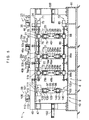
- the chamfering means 10 includes a chamfering drill 95 for chamfering the edge 12 of the opening of the recess 5 in the upper surface 4 of the glass plate 3; a chamfering drill 96 for chamfering the edge 13 of the opening of the recess 6 in the lower surface 7 of the glass plate 3; electric motors 97 and 98 for respectively rotating the chamfering drills 95 and 96; a chamfering-drill moving means 99 for moving the chamfering drills 95 and 96 synchronously in parallel to the upper surface 4 and the lower surface 7 of the glass plate 3, i.e., in the X direction and the Y direction; and a chamfering-drill vertically moving means 100 for vertically moving the chamfering drills 95 and 96 independently of each other with respect to the glass plate 3.
- the electric motors 97 and 98 are respectively connected at one ends of their output rotating shafts to the chamfering drills 95 and 96.
- the chamfering-drill moving means 99 has an X-direction moving device 101 for moving the chamfering drills 95 and 96 in the X direction with respect to the glass plate 3, as well as a Y-direction moving device 102 for moving the chamfering drills 95 and 96 in the Y direction with respect to the glass plate 3.
- the X-direction moving device 101 includes an electric motor 106 which shares the pair of guide rails 48 with the recess forming means 8 and is mounted on the frame 45; a movable frame 109 fitted in the guide rails 48 movably in the X direction; a nut 111 secured to an upper surface 110 of the movable frame 109; and a threaded shaft 115 which is threadedly engaged with the nut 111, is supported rotatably by the frame 45, and is connected to an output rotating shaft of the electric motor 106 through a pulley 112, a belt 113, and a pulley 114.
- the threaded shaft 115 is rotated through the pulley 112, the belt 113, and the pulley 114 by the operation of the electric motor 106. This rotation causes the nut 111 threadedly engaged with the threaded shaft 115 and the movable frame 109 with the nut 111 secured thereto to move in the X direction.
- the arrangement provided is such that the chamfering drills 95 and 96 are thereby moved synchronously in the X direction with respect to the glass plate 3 through movable bases 139 and 149 mounted on the movable frame 109 as well as the electric motors 97 and 98.
- the Y-direction moving device 102 includes an electric motor 122 mounted on the base 61; a threaded shaft 123 which is rotatably supported on the base 61, is connected to one end of an output rotating shaft of the electric motor 122, and extends in the Y direction; a nut 124 threadedly engaged with the threaded shaft 123; a pair of guide rails 125 which are secured to the base 61, are disposed with the threaded shaft 123 positioned therebetween, and extend in the Y direction; a movable base 126 to which the nut 124 is secured and which is fitted to the guide rails 125 movably in the Y direction; and a holding base 128 fixed to the movable base 126 and supporting the glass plate 3.
- the threaded shaft 123 is rotated by the operation of the electric motor 122. This rotation causes the nut 124 threadedly engaged with the threaded shaft, the movable base 126 with the nut 124 secured thereto, and the holding base 128 secured to the movable base 126 to move in the Y direction.
- the arrangement provided is such that the glass plate 3 held on the holding base 128 is thereby moved synchronously in the Y direction with respect to the chamfering drills 95 and 96.
- the holding base 128 includes a holding base body 129 mounted on the movable base 126; a suction pad 130 fixed to an upper surface of the holding base body 129; a suction port (not shown) provided in the suction pad 130; and a vacuum suction unit (not shown) communicating with the suction port.
- the arrangement provided is such that as this vacuum suction unit is operated, the lower surface 7 of the glass plate 3 placed directly on the suction pad 130 is sucked under a vacuum through the suction port communicating with the vacuum suction unit, thereby sucking and holding the glass plate 3.
- the chamfering-drill vertically moving means 100 has a chamfering-drill vertically moving device 131 for raising and lowering the chamfering drill 95, as well as a chamfering-drill vertically moving device 132 disposed in such a manner as to oppose the chamfering-drill vertically moving device 131 in the Z direction and adapted to raise and lower the chamfering drills 96.
- the chamfering-drill vertically moving device 131 includes an electric motor 135 mounted on the movable frame 109; a threaded shaft 137 which is rotatably supported on the movable frame 109, is connected to one end of an output rotating shaft of the electric motor 135, and extends in the Z direction; a pair of guide rails fixed to the movable frame 109 and extending in the Z direction; a nut (not shown) threadedly engaged with the threaded shaft 137; and the movable base 139 to which the nut is secured, which is fitted to the pair of guide rails, on which the electric motor 97 is mounted, and which is movable in the Z direction.
- the rotation of the output rotating shaft of the electric motor 135 due to its operation rotates the threaded shaft 137.
- the arrangement provided is such that the chamfering drill 95 is thereby raised and lowered in the Z direction through the nut threadedly engaged with the threaded shaft 137, the movable base 139 to which the nut is secured, and the like.
- the chamfering-drill vertically moving device 132 includes an electric motor 145 mounted on the movable frame 109; a threaded shaft 147 which is rotatably supported on the movable frame 109, is connected to one end of an output rotating shaft of the electric motor 145, and extends in the Z direction; a pair of guide rails fixed to the movable frame 109 and extending in the Z direction; a nut (not shown) threadedly engaged with the threaded shaft 147; and the movable base 149 to which the nut is secured, which is fitted to the pair of guide rails, on which the electric motor 98 is mounted, and which is movable in the Z direction.
- the rotation of the output rotating shaft of the electric motor 145 due to its operation rotates the threaded shaft 147.
- the arrangement provided is such that the chamfering drill 96 is thereby raised and lowered in the Z direction through the nut threadedly engaged with the threaded shaft 147, the movable base 149 to which the nut is secured, and the like.
- the above-described chamfering means 10 is so arranged as to synchronously chamfer the edges 12 and 13 at the portion P1 of the glass plate 3, which is sucked and held by the holding base 128, by the chamfering drills 95 and 96, to synchronously chamfer the edges 12 and 13 at the portion P2 by the chamfering drills 95 and 96, and to synchronously chamfer the edges 12 and 13 at the portion P3 by the chamfering drills 95 and 96.
- the chamfering means 10 may be so arranged as to chamfer the edge 12 by the chamfering drill 95 and subsequently chamfer the edge 13 by the chamfering drill 96. Still alternatively, the chamfering means 10 may be so arranged as to chamfer the edge 13 by the chamfering drill 96 and subsequently chamfer the edge 12 by the chamfering drill 95.
- the recess forming drills 25, 26, 25a, 26a, 25b, and 26b and the chamfering drills 95 and 96 it is preferable to use hollow or solid core drills or the like impregnated with diamond abrasive grains.
- the transporting means 11 includes a placing table 159 on which the glass plate 3 to be drilled is placed; a placing table 160 on which the drilled glass plate 3 is placed; lifting devices 161, 162, 163, 164, and 165 for respectively lifting the glass plates 3 on the placing table 159 and the holding bases 68, 68a, 68b, and 128; and a glass-plate moving means 166 for moving in the X direction the glass plates 3 being respectively lifted by the lifting devices 161, 162, 163, 164, and 165.
- the lifting devices 161, 162, 163, 164, and 165 are respectively juxtaposed in the X direction at equal intervals.
- the placing table 159 is disposed on the glass plate 3 carrying-in end side of the apparatus 1 for drilling a hole in a glass plate, while the placing table 160 is disposed on the glass plate 3 carrying-out end side of the apparatus 1 for drilling a hole in a glass plate.
- the placing tables 159 and 160 and the holding bases 68, 68a, 68b, and 128 are respectively arranged in the X direction at mutually equal intervals.
- Each of the lifting devices 161, 162, 163, 164, and 165 has a suction cup head 171 for sucking the glass plate 3 and a cylinder unit 172 for raising or lowering the suction cup head 171.
- the arrangement provided is such that the glass plate 3 is sucked by the suction cup head 171, and the sucked glass plate 3 is raised by the cylinder unit 172 so as to lift the glass plate 3.
- Each of the suction cup heads 171 has a vacuum suction unit (not shown) for sucking under a vacuum the glass plate 3, a suction port communicating with this vacuum suction unit, and a suction pad 173 provided with this suction port.
- the arrangement provided is such that as the vacuum suction unit is operated, the upper surface 4 of the glass plate 3 is sucked under a vacuum so as to suck and fix the glass plate 3.
- Each of the cylinder units 172 consists of a cylinder and a piston rod, and the suction cup head 171 is attached to a distal end of the piston rod.
- the arrangement provided is such that the piston rod is extended or retracted by air pressure or fluid pressure such as oil pressure applied to the interior of the cylinder, so as to raise or lower the suction cup head 171.
- the glass-plate moving means 166 includes a frame 175 juxtaposed to the frame 45 and extending in the X direction; an electric motor 176 mounted on the frame 175; a pair of guide rails 177 mounted on the frame 175 and extending in the X direction; a movable base 178 fitted in the guide rails 177 movably in the X direction; a nut 179 secured to the movable base 178; a threaded shaft 183 which is threadedly engaged with the nut 179, is supported rotatably by the frame 175, is connected to an output rotating shaft of the electric motor 176 through a pulley 180, a belt 181, and a pulley 182, and extends in the X direction; and a bracket 184 which is secured at its one end to the movable base 178 and is secured at its other end to the respective cylinders of the lifting devices 161, 162, 163, 164, and 165.
- the above-described transporting means 11 is arranged as follows: The suction cup head 171 is lowered by the cylinder unit 172 of the lifting device 161 to cause the suction pad 173 to abut against the upper surface 4 of the glass plate 3 on the placing table 159. The upper surface 4 of the abutted glass plate 3 is sucked under a vacuum at the suction port by the operation of the vacuum suction unit of the suction cup head 171 so as to suck and fix the glass plate 3. The sucked and fixed glass plate 3 is raised by the cylinder unit 172, and the raised glass plate 3 is moved in the X direction by the glass-plate moving means 166 through the lifting device 161 so as to be disposed above the holding base 68.
- the glass plate 3 disposed above the holding base 68 is lowered by the chamfering drill 172 so as to be placed on the holding base 68. Subsequently, the suction and fixing of the glass plate 3 by the suction cup head 171 is canceled, thereby transporting the glass plate 3 from the placing table 159 onto the holding base 68.
- the transporting means 11 is arranged such that, in order to transport another glass plate 3 from the placing table 159 onto the holding base 68, the suction cup head 171 is raised by the cylinder unit 172, and the lifting device 161 is moved in the X direction by the glass-plate moving means 166 so as to be disposed above the placing table 159. It should be noted that the transporting means 11 is adapted to consecutively transport a plurality of glass plates 3 from the placing table 159 onto the holding base 68 by repeatedly effecting such a transporting operation.
- the transporting means 11 is also adapted to operate the respective lifting devices 162, 163, 164, and 165 in the same way as the lifting device 161, thereby consecutively transporting the glass plate 3 on the holding base 68 onto the holding base 68a, the glass plate 3 on the holding base 68a onto the holding base 68b, the glass plate 3 on the holding base 68b onto the holding base 128, the glass plate 3 on the holding base 128 onto the placing table 160, respectively.
- the numerical controller is adapted to control the electric motors 46, 46a, 46b, 62, 62a, 62b, 75, 85, 106, 122, 135, 145, and 176, the aforementioned vacuum suction units, and the cylinder units 172 by numerical control commands based on a program stored in advance.
- a numerical controller is embodied by using, for example, a microcomputer or the like.
- the glass plate 3 which is placed on the placing table 159 and in which in the recesses 5 and 6 are to be formed, is first lifted by the lifting device 161.
- the lifted glass plate 3 is moved in the X direction by the glass-plate moving means 166 and is disposed above the holding base 68, and the glass plate 3 disposed above the holding base 68 is lowered by the lifting device 161 and is placed on the holding base 68.
- the glass plate 3 is sucked and held by the holding base 68, and the recess forming drills 25 and 26 are moved in the X direction and the Y direction with respect to the glass plate 3 by the X-direction moving device 35 and the Y-direction moving device 36, to respectively dispose the recess forming drills 25 and 26 above and below the portion P1 of the glass plate 3.
- the recess forming drills 25 and 26 are respectively disposed above and below the portion P1
- the recess forming drill 25 is rotated by the operation of the electric motor 27, and the recess forming drill 25 is lowered by the recess-forming-drill vertically moving device 71.
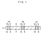
- the recess 5 is thereby formed at the portion P1 in the upper surface 4 of the glass plate 3 with such a depth that a crack, a break, or the like does not occur in the lower surface 7 of the glass plate 3.
- the recess forming drill 25 is raised by the recess-forming-drill vertically moving device 71.
- the recess forming drill 26 is rotated by the operation of the electric motor 28, and the recess 6 communicating with the recess 5 at the portion P1 is formed at the portion P1 in the lower surface 7 of the glass plate 3 by raising the recess forming drill 26 by the recess-forming-drill vertically moving device 72.
- the recess forming drill 26 is raised by the recess-forming-drill vertically moving device 72. After the recesses 5 and 6 are formed at the portion P1 of the glass plate 3 by the recess forming drills 25 and 26, the suction and holding of the glass plate 3 by the holding base 68 is canceled.
- the glass plate 3 which is placed on the holding base 68 and in which the recesses 5 and 6 have been formed at the portion P3, is lifted by the lifting device 162.
- the lifted glass plate 3 is moved in the X direction by the glass-plate moving means 166 and is disposed above the holding base 68a, and the glass plate 3 disposed above the holding base 68a is lowered by the lifting device 162 and is placed on the holding base 68a.
- the glass plate 3 is sucked and held by the holding base 68a, and the recess forming drills 25a and 26a are moved in the X direction and the Y direction with respect to the glass plate 3 by the X-direction moving device 35a and the Y-direction moving device 36a, to respectively dispose the recess forming drills 25a and 26a above and below the portion P2 of the glass plate 3.
- the recess forming drills 25a and 26a are respectively disposed above and below the portion P2
- the recess forming drill 25a is rotated by the operation of the electric motor 27a, and the recess forming drill 25a is lowered by the recess-forming-drill vertically moving device 71.
- the recess 5 is thereby formed at the portion P2 in the upper surface 4 of the glass plate 3 with such a depth that a crack, a break, or the like does not occur in the lower surface 7 of the glass plate 3.
- the recess forming drill 25a is raised by the recess-forming-drill vertically moving device 71.
- the recess forming drill 26a is rotated by the operation of the electric motor 28a, and the recess 6 communicating with the recess 5 at the portion P2 is formed at the portion P2 in the lower surface 7 of the glass plate 3 by raising the recess forming drill 26a by the recess-forming-drill vertically moving device 72.
- the recess forming drill 26a is raised by the recess-forming-drill vertically moving device 72. After the recesses 5 and 6 are formed at the portion P2 of the glass plate 3 by the recess forming drills 25a and 26a, the suction and holding of the glass plate 3 by the holding base 68a is canceled.
- the glass plate 3 which is placed on the holding base 68a and in which the recesses 5 and 6 have been formed at the portion P2, is lifted by the lifting device 163.
- the lifted glass plate 3 is moved in the X direction by the glass-plate moving means 166 and is disposed above the holding base 68b, and the glass plate 3 disposed above the holding base 68b is lowered by the lifting device 163 and is placed on the holding base 68b.
- the glass plate 3 is sucked and held by the holding base 68b, and the recess forming drills 25b and 26b are moved in the X direction and the Y direction with respect to the glass plate 3 by the X-direction moving device 35b and the Y-direction moving device 36b, to respectively dispose the recess forming drills 25b and 26b above and below the portion P3 of the glass plate 3.
- the recess forming drills 25b and 26b are respectively disposed above and below the portion P3
- the recess forming drill 25b is rotated by the operation of the electric motor 27b, and the recess forming drill 25b is lowered by the recess-forming-drill vertically moving device 71.
- the recess 5 is thereby formed at the portion P3 in the upper surface 4 of the glass plate 3 with such a depth that a crack, a break, or the like does not occur in the lower surface 7 of the glass plate 3.
- the recess forming drill 25b is raised by the recess-forming-drill vertically moving device 71.
- the recess forming drill 26b is rotated by the operation of the electric motor 28b, and the recess 6 communicating with the recess 5 at the portion P3 is formed at the portion P3 in the lower surface 7 of the glass plate 3 by raising the recess forming drill 26b by the recess-forming-drill vertically moving device 72.
- the recess forming drill 26b is raised by the recess-forming-drill vertically moving device 72. After the recesses 5 and 6 are formed at the portion P3 of the glass plate 3 by the recess forming drills 25b and 26b, the suction and holding of the glass plate 3 by the holding base 68b is canceled.
- the recess forming drills 25, 25a, and 25b since they are respectively raised and lowered synchronously with each other by the recess-forming-drill vertically moving device 71, the recess forming drills 25, 25a, and 25b synchronously form the recesses 5 to be formed in the glass plates 3 being respectively sucked and held by the holding bases 68, 68a, and 68b.
- the recess forming drills 26, 26a, and 26b since they are respectively raised and lowered synchronously with each other by the recess-forming-drill vertically moving device 72, the recess forming drills 26, 26a, and 26b synchronously form the recesses 6 to be formed in the glass plates 3 being respectively sucked and held by the holding bases 68, 68a, and 68b.
- the glass plate 3 which is placed on the holding base 68b and in which the recesses 5 and 6 to be formed have been formed, is lifted by the lifting device 164.
- the lifted glass plate 3 is moved in the X direction by the glass-plate moving means 166 and is disposed above the holding base 128, and the glass plate 3 disposed above the holding base 128 is lowered by the lifting device 164 and is placed on the holding base 128.
- the glass plate 3 is sucked and held by the holding base 128, and the chamfering drills 95 and 96 are moved in the X direction and the Y direction with respect to the glass plate 3 by the X-direction moving device 101 and the Y-direction moving device 102, to respectively dispose the chamfering drills 95 and 96 above and below the portion P1 of the glass plate 3.
- the chamfering drills 95 and 96 are respectively disposed above and below the portion P1
- the chamfering drills 95 and 96 are respectively rotated by the operation of the electric motors 97 and 98.
- the chamfering drill 95 is lowered, and the chamfering drill 96 is raised in synchronism with that lowering.
- the edges 12 and 13 of the opening of each of the recesses 5 and 6 at the portion P1 of the glass plate 3 are synchronously chamfered.
- the chamfering drill 95 is raised and the chamfering drill 96 is lowered by the chamfering-drill vertically moving devices 131 and 132 such that the chamfering drills 95 and 96 do not come into contact with the upper surface 4 and the lower surface 7 of the glass plate 3.
- the chamfering drills 95 and 96 are moved by the X-direction moving device 101 and the Y-direction moving device 102, and are respectively disposed above and below the portion P2 of the glass plate.
- the chamfering drills 95 and 96 are respectively lowered and raised synchronously by the chamfering-drill vertically moving devices 131 and 132.
- the edges 12 and 13 of the opening of each of the recesses 5 and 6 at the portion P2 of the glass plate 3 are synchronously chamfered.
- the chamfering drill 95 is raised and the chamfering drill 96 is lowered by the chamfering-drill vertically moving devices 131 and 132 such that the chamfering drills 95 and 96 do not come into contact with the upper surface 4 and the lower surface 7 of the glass plate 3.
- the chamfering drills 95 and 96 are moved by the X-direction moving device 101 and the Y-direction moving device 102, and are respectively disposed above and below the portion P1 of the glass plate.
- the chamfering drills 95 and 96 are respectively lowered and raised synchronously by the chamfering-drill vertically moving devices 131 and 132.
- the edges 12 and 13 of the opening of each of the recesses 5 and 6 at the portion P3 of the glass plate 3 are synchronously chamfered.
- the chamfering drill 95 is raised and the chamfering drill 96 is lowered by the chamfering-drill vertically moving devices 131 and 132. After the edges 12 and 13 are chamfered at the portions P1, P2, and P3 of the glass plate 3, the suction and holding of the glass plate 3 by the holding base 128 is canceled.
- the drilled glass plate 3 on the holding base 128 is lifted by the lifting device 165.
- the lifted glass plate 3 is moved in the X direction by the glass-plate moving means 166 and is disposed above the placing table 160.
- the glass plate 3 disposed above the placing table 160 is lowered by the lifting device 161 and is placed on the placing table 160.
- the glass plates 3 are consecutively transported by the transporting means 11, the recesses 5 and 6 are formed in the consecutively transported glass plates 3 on the holding bases 68, 68a, and 68b by the recess forming devices 20, 21, and 22.
- the glass plate 3 on the holding base 128, where the recesses 5 and 6 have been formed at the respective portions P1, P2, and P3 by the recess forming means 8 is provided with the chamfering of the edges 12 and 13 by the chamfering means 10, thereby consecutively effecting drilling in the multiplicity of glass plates 3.
- the operation of forming recesses by the recess forming means 8 and the operation of chamfering by the chamfering means 10 are respectively controlled independently of each other by the numerical controller.
- the respective operations can be controlled by the numerical controller using a simple program.
- the apparatus 1 for drilling a hole in a glass plate in this embodiment may be provided with, instead of the recess forming means 8, a recess forming means having one or a plurality of recess forming devices provided in the number of portions to be drilled in the glass plate 3 and adapted to move each pair of recess forming drills of the recess forming devices in the X and Y directions and to vertically move them in the Z direction.
- the apparatus 1 for drilling a hole in a glass plate may be provided with, instead of the chamfering means 10, a chamfering means having a plurality of pairs of chamfering drills provided in the number of portions to be drilled in the glass plate 3 and adapted to move each pair of chamfering drills in the X and Y directions and to vertically move them in the Z direction.
- a chamfering means having a plurality of pairs of chamfering drills provided in the number of portions to be drilled in the glass plate 3 and adapted to move each pair of chamfering drills in the X and Y directions and to vertically move them in the Z direction.
Landscapes
- Engineering & Computer Science (AREA)
- Mechanical Engineering (AREA)
- Chemical & Material Sciences (AREA)
- Ceramic Engineering (AREA)
- Inorganic Chemistry (AREA)
- Re-Forming, After-Treatment, Cutting And Transporting Of Glass Products (AREA)
- Processing Of Stones Or Stones Resemblance Materials (AREA)
Applications Claiming Priority (3)
| Application Number | Priority Date | Filing Date | Title |
|---|---|---|---|
| JP2002191502 | 2002-06-28 | ||
| JP2002191502A JP4082107B2 (ja) | 2002-06-28 | 2002-06-28 | ガラス板の孔開け方法及びその装置 |
| PCT/JP2003/006759 WO2004002704A1 (ja) | 2002-06-28 | 2003-05-29 | ガラス板の孔開け方法及びその装置 |
Publications (2)
| Publication Number | Publication Date |
|---|---|
| EP1518651A1 true EP1518651A1 (de) | 2005-03-30 |
| EP1518651A4 EP1518651A4 (de) | 2008-05-21 |
Family
ID=29996931
Family Applications (1)
| Application Number | Title | Priority Date | Filing Date |
|---|---|---|---|
| EP03733154A Withdrawn EP1518651A4 (de) | 2002-06-28 | 2003-05-29 | Verfahren und vorrichtung zur herstellung von löchern in einer glasplatte |
Country Status (4)
| Country | Link |
|---|---|
| US (1) | US20040179908A1 (de) |
| EP (1) | EP1518651A4 (de) |
| JP (1) | JP4082107B2 (de) |
| WO (1) | WO2004002704A1 (de) |
Cited By (5)
| Publication number | Priority date | Publication date | Assignee | Title |
|---|---|---|---|---|
| CN102898011A (zh) * | 2011-07-25 | 2013-01-30 | 信义光伏产业(安徽)控股有限公司 | 一种卧式玻璃件加工设备 |
| CN104148945A (zh) * | 2014-07-31 | 2014-11-19 | 浙江昌煜机械制造有限公司 | 线性滑轨专用数控钻床 |
| CN110181357A (zh) * | 2019-05-07 | 2019-08-30 | 徐建方 | 一种水晶玻璃倒边的磨抛机构 |
| CN111331319A (zh) * | 2020-03-18 | 2020-06-26 | 余萍 | 一种太阳能热水器内胆自动打孔打磨工艺 |
| EP3640219A4 (de) * | 2018-03-30 | 2020-12-23 | Bando Kiko Co., Ltd. | Vorrichtung zur herstellung von löchern in einer glasplatte |
Families Citing this family (10)
| Publication number | Priority date | Publication date | Assignee | Title |
|---|---|---|---|---|
| JPWO2006038283A1 (ja) * | 2004-10-05 | 2008-05-15 | 坂東機工株式会社 | ガラス板の孔開け装置 |
| WO2006112019A1 (ja) * | 2005-04-14 | 2006-10-26 | Bando Kiko Co., Ltd. | ガラス板の孔開け方法及びその装置 |
| ITBS20110147A1 (it) * | 2011-10-24 | 2013-04-25 | Cms Spa | Macchina per lavorazione di lastre di vetro |
| CN106141846A (zh) * | 2016-08-19 | 2016-11-23 | 四川省聚荣兴安全玻璃有限责任公司 | 一种智能异形玻璃内角磨边机 |
| CN107225263A (zh) * | 2017-06-13 | 2017-10-03 | 中信戴卡股份有限公司 | 多功能可调钻机 |
| CN108098502A (zh) * | 2017-12-18 | 2018-06-01 | 深圳市吉祥云科技有限公司 | 一种玻璃孔倒角的加工方法 |
| CN108356648B (zh) * | 2018-02-08 | 2020-06-16 | 湖北安达精密工业有限公司 | 一种内燃机轴瓦加工设备及其加工方法 |
| CN110815589A (zh) * | 2019-11-28 | 2020-02-21 | 刘洋 | 一种玻璃自动打孔磨边装置 |
| JP7141662B2 (ja) * | 2020-02-18 | 2022-09-26 | 坂東機工株式会社 | ガラス板の孔開け装置 |
| CN115091300A (zh) * | 2022-07-27 | 2022-09-23 | 海安常州大学高新技术研发中心 | 一种带打孔功能的玻璃磨边机 |
Family Cites Families (21)
| Publication number | Priority date | Publication date | Assignee | Title |
|---|---|---|---|---|
| US2620687A (en) * | 1949-03-11 | 1952-12-09 | Bausch & Lomb | Lens drilling machine |
| US7065856B1 (en) * | 1954-07-28 | 2006-06-27 | Lemelson Jerome H | Machine tool method |
| US3461615A (en) * | 1966-03-24 | 1969-08-19 | Libbey Owens Ford Glass Co | Drilling machines |
| US3576540A (en) * | 1967-11-20 | 1971-04-27 | Sundstrand Corp | Plural machine tool and part handling control system |
| US3559257A (en) * | 1968-03-12 | 1971-02-02 | Jerome H Lemelson | Machine control apparatus |
| US3559256A (en) * | 1968-03-12 | 1971-02-02 | Jerome H Lemelson | Machine control apparatus |
| US3813820A (en) * | 1973-03-29 | 1974-06-04 | Engelhard Min & Chem | Sheet glass core drilling machine |
| JPS5355594A (en) * | 1976-10-29 | 1978-05-20 | Hoya Lens Co Ltd | Drilling machine |
| IT1169821B (it) * | 1983-09-13 | 1987-06-03 | Teax Srl | Macchina per la foratura di materiali lastriformi fragili,in paticolare di lastre in vetro e simili |
| US5028176A (en) * | 1989-02-10 | 1991-07-02 | Toledo Automated Concepts, Inc. | Glass drilling machine with cooling fluid back pressure control system |
| US4955763A (en) * | 1989-02-10 | 1990-09-11 | Toledo Automated Concepts, Inc. | Glass drilling machine |
| US5116169A (en) * | 1991-03-01 | 1992-05-26 | Abb Power T&D Company, Inc. | Apparatus and method for drilling glass |
| US5152641A (en) * | 1991-10-15 | 1992-10-06 | Royal Tool, Inc. | Method and apparatus for controlling glass drilling |
| IT1282539B1 (it) * | 1995-09-19 | 1998-03-26 | Facom S R L | Macchina per la foratura e fresatura automatica di lastre di vetro |
| JPH11149669A (ja) * | 1997-11-14 | 1999-06-02 | Hokuto:Kk | 記録媒体用基板の内径外径同時研削方法 |
| JPH11349354A (ja) * | 1998-06-08 | 1999-12-21 | Nikon Corp | 情報記録媒体用基板及びその製造方法 |
| JP3502551B2 (ja) * | 1998-10-21 | 2004-03-02 | ユーテック株式会社 | 液晶パネルの面取り装置 |
| JP2000311616A (ja) * | 1999-04-28 | 2000-11-07 | Dainippon Printing Co Ltd | プラズマディスプレイパネル基板の排気孔 |
| JP2001071323A (ja) * | 1999-08-31 | 2001-03-21 | Bando Kiko Kk | ガラス板における孔開け装置 |
| CN2484158Y (zh) * | 2001-06-01 | 2002-04-03 | 苗正华 | 硬脆材料钻孔机 |
| US6722959B2 (en) * | 2002-03-22 | 2004-04-20 | Glassline Corporation | Combination 2-plane CNC positioning grinder with CNC positioning drill |
-
2002
- 2002-06-28 JP JP2002191502A patent/JP4082107B2/ja not_active Expired - Fee Related
-
2003
- 2003-05-29 EP EP03733154A patent/EP1518651A4/de not_active Withdrawn
- 2003-05-29 US US10/485,028 patent/US20040179908A1/en not_active Abandoned
- 2003-05-29 WO PCT/JP2003/006759 patent/WO2004002704A1/ja not_active Ceased
Non-Patent Citations (2)
| Title |
|---|
| No further relevant documents disclosed * |
| See also references of WO2004002704A1 * |
Cited By (8)
| Publication number | Priority date | Publication date | Assignee | Title |
|---|---|---|---|---|
| CN102898011A (zh) * | 2011-07-25 | 2013-01-30 | 信义光伏产业(安徽)控股有限公司 | 一种卧式玻璃件加工设备 |
| CN102898011B (zh) * | 2011-07-25 | 2016-02-03 | 信义光伏产业(安徽)控股有限公司 | 一种卧式玻璃件加工设备 |
| CN104148945A (zh) * | 2014-07-31 | 2014-11-19 | 浙江昌煜机械制造有限公司 | 线性滑轨专用数控钻床 |
| CN104148945B (zh) * | 2014-07-31 | 2016-06-22 | 浙江昌煜机械制造有限公司 | 线性滑轨专用数控钻床 |
| EP3640219A4 (de) * | 2018-03-30 | 2020-12-23 | Bando Kiko Co., Ltd. | Vorrichtung zur herstellung von löchern in einer glasplatte |
| CN110181357A (zh) * | 2019-05-07 | 2019-08-30 | 徐建方 | 一种水晶玻璃倒边的磨抛机构 |
| CN110181357B (zh) * | 2019-05-07 | 2020-12-25 | 湖南晶典饰品有限公司 | 一种水晶玻璃倒边的磨抛机构 |
| CN111331319A (zh) * | 2020-03-18 | 2020-06-26 | 余萍 | 一种太阳能热水器内胆自动打孔打磨工艺 |
Also Published As
| Publication number | Publication date |
|---|---|
| US20040179908A1 (en) | 2004-09-16 |
| EP1518651A4 (de) | 2008-05-21 |
| JP2004034371A (ja) | 2004-02-05 |
| JP4082107B2 (ja) | 2008-04-30 |
| WO2004002704A1 (ja) | 2004-01-08 |
Similar Documents
| Publication | Publication Date | Title |
|---|---|---|
| US8740514B2 (en) | Method of drilling holes in a glass plate and apparatus thereof | |
| US20040179908A1 (en) | Brake rotating body of vehicle | |
| EP1834930B1 (de) | Vorrichtung zur Bearbeitung von Glasscheiben | |
| KR100664717B1 (ko) | 유리판의 가공기계 | |
| EP3345874B1 (de) | Glasplattenverarbeitungsvorrichtung | |
| KR100745177B1 (ko) | 유리판의 가공방법 및 그 장치 | |
| EP0491055B1 (de) | Vorrichtung zum schneiden von glasplatten | |
| CN103118840B (zh) | 自动测量和校正玻璃板加工尺寸的方法以及玻璃板加工设备 | |
| EP2762273B1 (de) | Werkzeugmaschine | |
| JP4567298B2 (ja) | ガラス板の孔開け方法及びその装置 | |
| KR100363440B1 (ko) | 유리판의가공장치 | |
| CN115091322A (zh) | 用于hdi多层电路板外端面精密打磨的设备及打磨方法 | |
| CN108789868A (zh) | 一种高效的玻璃打孔机 | |
| CN108581802B (zh) | 一种具有剪切功能的自动抛光机 | |
| CN210190187U (zh) | 一种桥式切石机 | |
| JP2010254573A (ja) | ガラス板の孔開け方法及びその装置 | |
| JPH07206158A (ja) | 物品移送装置 | |
| JP2001071323A (ja) | ガラス板における孔開け装置 | |
| CN217943814U (zh) | 一种适用于多板材的内孔切磨一体机 | |
| CN208451969U (zh) | 一种钻孔机 | |
| JP2006159377A (ja) | ガラス板の加工装置 | |
| CN223643375U (zh) | 一种轮毂打磨装置 | |
| CN210254334U (zh) | 全自动六工位智能龙门钻床 | |
| CN218170953U (zh) | 一种新型可连线生产的圆孔机械倒角设备 | |
| CN111875241A (zh) | 一种板材切割槽延展切割装置 |
Legal Events
| Date | Code | Title | Description |
|---|---|---|---|
| PUAI | Public reference made under article 153(3) epc to a published international application that has entered the european phase |
Free format text: ORIGINAL CODE: 0009012 |
|
| 17P | Request for examination filed |
Effective date: 20040301 |
|
| AK | Designated contracting states |
Kind code of ref document: A1 Designated state(s): AT BE BG CH CY CZ DE DK EE ES FI FR GB GR HU IE IT LI LU MC NL PT RO SE SI SK TR |
|
| RBV | Designated contracting states (corrected) |
Designated state(s): CH DE FR GB IT LI |
|
| A4 | Supplementary search report drawn up and despatched |
Effective date: 20080423 |
|
| STAA | Information on the status of an ep patent application or granted ep patent |
Free format text: STATUS: THE APPLICATION HAS BEEN WITHDRAWN |
|
| 18W | Application withdrawn |
Effective date: 20090811 |