EP1517196B1 - Bildformungsapparat mit versenkbarem Griff - Google Patents
Bildformungsapparat mit versenkbarem Griff Download PDFInfo
- Publication number
- EP1517196B1 EP1517196B1 EP04022181A EP04022181A EP1517196B1 EP 1517196 B1 EP1517196 B1 EP 1517196B1 EP 04022181 A EP04022181 A EP 04022181A EP 04022181 A EP04022181 A EP 04022181A EP 1517196 B1 EP1517196 B1 EP 1517196B1
- Authority
- EP
- European Patent Office
- Prior art keywords
- handle
- hole
- image forming
- forming apparatus
- wall
- Prior art date
- Legal status (The legal status is an assumption and is not a legal conclusion. Google has not performed a legal analysis and makes no representation as to the accuracy of the status listed.)
- Expired - Lifetime
Links
- 238000003384 imaging method Methods 0.000 description 2
- 239000002184 metal Substances 0.000 description 2
- 230000001419 dependent effect Effects 0.000 description 1
- 239000007769 metal material Substances 0.000 description 1
- 230000004048 modification Effects 0.000 description 1
- 238000012986 modification Methods 0.000 description 1
- 230000003014 reinforcing effect Effects 0.000 description 1
Images


Classifications
-
- G—PHYSICS
- G03—PHOTOGRAPHY; CINEMATOGRAPHY; ANALOGOUS TECHNIQUES USING WAVES OTHER THAN OPTICAL WAVES; ELECTROGRAPHY; HOLOGRAPHY
- G03G—ELECTROGRAPHY; ELECTROPHOTOGRAPHY; MAGNETOGRAPHY
- G03G21/00—Arrangements not provided for by groups G03G13/00 - G03G19/00, e.g. cleaning, elimination of residual charge
- G03G21/16—Mechanical means for facilitating the maintenance of the apparatus, e.g. modular arrangements
- G03G21/1604—Arrangement or disposition of the entire apparatus
- G03G21/1623—Means to access the interior of the apparatus
- G03G21/1633—Means to access the interior of the apparatus using doors or covers
Definitions
- the present invention relates to an image forming apparatus, such as a copier, printer, or fax machine, having a handle that is supported so as to be able to go in and out of a hole provided in an outer wall, and designed so that the handle can be firmly grasped and used effectively despite the presence of an obstruction near the handle, so that the apparatus, which is a heavy object, can be transported or moved more easily.
- an image forming apparatus such as a copier, printer, or fax machine
- Some conventional printers, fax machines, and other such image forming apparatus are designed such that a retractable handle is provided in a hole made in an outer wall of the apparatus main body so that a person can lift the apparatus by grasping a place on the outer wall when the apparatus is to be moved.
- a system in which the handle is slidably stowed within the apparatus main body is usually used for the sake of lower cost and a simpler mechanism.
- the handle With a system such as this, not only must the handle bear a heavy weight during transport, and be able to slide over a high-strength frame located on the inside of the outer wall, but the handle must also be disposed in a location that will afford a good weight balance when the handle is grasped and the apparatus moved, so the handle can only be disposed in a limited number of locations on the apparatus main body.
- JP 10-020601 relates to an image forming device.
- the handle fixing means is provided with a pawl part, which is locked in a hole or a groove being a locking part formed on a holding bracket.
- the locking part is plural holes or grooves radially and discontinuously formed with the pin of a plate-like holding means as center.
- the pawl part is hooked and locked in the locking part, so that the handle is selectively fixed at the optional turning position. Since the holes or the groove constituting the locking part consist of plural steps, that is, three steps, they are fixed at the selected position at which a user can hold the device most easily by adjusting the length of pulling out the handle from the main body.
- JP 07-140274 relates to a clerical work equipment. Apertures are opened at the lower parts of the lateral side faces of an equipment body, and a handle is provided in such a way as to be enclosed in and pulled out of the equipment body through the apertures.
- the handle is formed into straight rod shape, and the tip of the handle is provided with a finger hook part used at the time of pulling the handle out of the equipment body.
- JP 2002-307781 relates to an imaging apparatus.
- a flat end having a U-shaped cross section is formed to a side plate which constitutes an apparatus body.
- a screw is passed through in a manner to be supported at both ends by the flat end and the side plate. The weight of the imaging apparatus itself applied to the carry handle is thus supported by the flat end and the screw.
- a hole is set to the side plate to insert the carry handle into a hollow between the flat end and the side plate.
- a notched groove is formed to the carry handle to be fitted to an edge of the hole, thereby preventing the handle from slipping off and intruding.
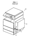
- Fig. 1 illustrates the configuration of the handle in a conventional image forming apparatus.
- a hole 102 is made at a suitable location in an outer wall 101 of an image forming apparatus 100.
- a handle 103 made of a metal material can be pulled out of and pushed into this hole 102.
- the direction in which the handle 103 protrudes is horizontal and perpendicular to the outer face of the outer wall 101.
- the handle 103 must bear a heavy weight during transport, not only must it be able to slide over a high-strength frame located on the inside of the outer wall, but the handle must also be disposed in a location that will afford a good weight balance when the handle is grasped and the apparatus moved, so the handle can only be disposed in a limited number of locations on the apparatus main body. Because the disposition of the handle is thus limited to a relatively narrow range of suitable places, it is frequently the case that an obstruction 104, consisting of an optional unit such as a double-side printing unit, is present just to the side of the hole 102. In such a case, the layout restrictions imposed by this obstruction 104 result in an extremely narrow gap A between the extended handle 103 and the obstruction 104, which makes it difficult for a worker to get a good grip, and requires that the lifting be done in an awkward posture.
- an obstruction 104 consisting of an optional unit such as a double-side printing unit
- the image forming apparatus 1 pertaining to this embodiment has a hole 3 at the front part of an outer wall (housing) 2 of the apparatus main body.
- a straight metal handle 4 is supported such that it can move in and out of the apparatus through this hole 3.
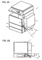
- a protruding component 5 consisting of an optional unit such as a double-side printing unit is disposed just to one side of the hole 3. Since only a slight gap B is present between the hole 3 and the front part of the protruding component 5, it is impossible to ensure enough space for a worker to insert a hand if the handle 4 is pulled out perpendicular to the outer wall 2.
- the handle 4 is supported by a frame 10 that is a strong internal component, as shown in Figs. 3 and 4 , the only place the hole 3 can be formed is a very small area around this frame.
- this embodiment is configured such that when the handle 4 has been pulled out from the hole 3, the entire handle 4 slidably protrudes horizontally at a specific inclination angle ⁇ away from the protruding component 5.
- a space B formed between the distal end of the extended handle 4 and the front end of the protruding component 5 is enough space for a person to insert a hand.
- FIG. 3 shows the state when the front housing panel has been removed from the image forming apparatus 1.
- a front panel 11 that constitutes a frame is located on the inside of the front housing panel, and an opening 12 for supporting the pull-out paper tray 6 shown in Fig. 2A is formed in the front panel 11.
- a horizontal, flat frame 10, which is a high-strength component, is fastened by screws or the like to the front of the front panel 11 (part of the outer wall 2) and to left and right side panels 11a.
- a bracket 15 is fastened diagonally on the frame 10, and the handle 4, produced by forming a sheet of metal into the required straight shape, is retractably supported within a support hole 15a in the bracket 15.
- the hole 3 is made in the outer wall 2 (side panel 11a) at a location corresponding to the distal end of the handle 4. In other words, the handle 4 can be moved in and out of the hole 3 by extending and retracting the handle along the bracket 15.
- the size of the support hole 15a of the bracket 15 is set to be large enough that the handle 4 can be tilted up and down as discussed below. Therefore, when the apparatus is moved by a service person, salesperson, or user, the handle 4 is pulled out from the apparatus main body as shown in Figs. 2A and 2B . When the handle 4 has been pulled out, as shown in Fig. 5 , the rear end 4a of the handle 4 catches on the upper surface of the frame 10 or on the edge of the support hole 15a of the bracket, so that the handle cannot be pulled out any farther.
- the handle 4 is disposed at a specific inclination angle ⁇ ( ⁇ ⁇ 90 degrees) with respect to the front panel 11, with the result being that the rear end 4a of the handle 4 is located nearer the front panel 11, which provides a strength advantage when the handle is subjected to a load.
- a protrusion 4c provided on the upper edge in the middle part of the handle 4 engages with the fulcrum portion of the side panel 11a (the upper edge of the hole 3) when this protrusion 4c moves outside of the hole 3, and this prevents the handle 4 from going back into the main body while the handle 4 is gripped.
- a bent portion 4d in the form of a horizontal tab bent laterally, is located as shown in Fig. 4 on the top edge of the rear end 4a of the handle 4. This bent portion 4d is used to keep the handle from coming out of the bracket hole 15a.
Landscapes
- Physics & Mathematics (AREA)
- General Physics & Mathematics (AREA)
- Accessory Devices And Overall Control Thereof (AREA)
- Electrophotography Configuration And Component (AREA)
Claims (4)
- Bilderzeugungsvorrichtung (1; 100), die mit einem Griff (4) ausgerüstet ist, der in eine Außenwand (11a; 2) durch ein in der Außenwand (11a; 2) vorgesehenes Loch (3) geschoben und aus ihr herausgezogen werden kann, wobei an der Außenwand (11a; 2) in der Umgebung des Lochs und nahe bei dem Loch (3) eine vorstehende Komponente (5) vorhanden ist und wobei an der Außenwand (11a, 2) ein horizontaler Rahmen (10) befestigt ist;wobei der Griff (4) in der Weise ausgebildet ist, dass der Griff (4) dann, wenn er aus dem Loch (3) herausgezogen wird, horizontal unter einem bestimmten Neigungswinkel (□) von der vorstehenden Komponente (5) gleitfähig vorsteht, wobei □ < 90 Grad, dadurch gekennzeichnet, dass an dem Rahmen (10) eine Unterstützung (15) diagonal befestigt ist und der Griff (4) in einem Unterstützungsloch (15a) der Unterstützung (15) zurückziehbar unterstützt ist.
- Bilderzeugungsvorrichtung nach Anspruch 1, wobei der Griff (4) in der Weise ausgebildet ist, dass der Griff in einem Zustand, in dem er aus dem Loch (3) herausgezogen worden ist, innerhalb eines bestimmten Bereichs in dem Loch (3) nach oben und nach unten geneigt werden kann.
- Bilderzeugungsvorrichtung nach einem der Ansprüche 1 oder 2, wobei der Abschnitt der Vorrichtung (1), der am hinteren Ende des Griffs (4) anliegt und einer Last unterliegt, wenn der Griff (4), der aus dem Loch (3) herausgezogen worden ist, ergriffen wird und eine nach oben gerichtete Last (L) ausgeübt wird, sich in der Umgebung des Rahmens (10) des Vorrichtungshauptkörpers befindet.
- Bilderzeugungsvorrichtung nach einem der Ansprüche 1 bis 3, wobei ein Abschnitt, der verhindert, dass der Griff (4) herabfällt, wenn er herausgezogen ist, nicht in einem vertikalen Plattenabschnitt, sondern in einem horizontalen Plattenabschnitt des Griffs (4) ausgebildet ist.
Applications Claiming Priority (2)
| Application Number | Priority Date | Filing Date | Title |
|---|---|---|---|
| JP2003326973A JP2005091946A (ja) | 2003-09-18 | 2003-09-18 | 画像形成装置 |
| JP2003326973 | 2003-09-18 |
Publications (2)
| Publication Number | Publication Date |
|---|---|
| EP1517196A1 EP1517196A1 (de) | 2005-03-23 |
| EP1517196B1 true EP1517196B1 (de) | 2008-07-30 |
Family
ID=34191364
Family Applications (1)
| Application Number | Title | Priority Date | Filing Date |
|---|---|---|---|
| EP04022181A Expired - Lifetime EP1517196B1 (de) | 2003-09-18 | 2004-09-17 | Bildformungsapparat mit versenkbarem Griff |
Country Status (4)
| Country | Link |
|---|---|
| US (1) | US7106990B2 (de) |
| EP (1) | EP1517196B1 (de) |
| JP (1) | JP2005091946A (de) |
| DE (1) | DE602004015383D1 (de) |
Cited By (1)
| Publication number | Priority date | Publication date | Assignee | Title |
|---|---|---|---|---|
| CN106126859A (zh) * | 2016-07-14 | 2016-11-16 | 长沙思胜智能设备有限公司 | 一种立式机床起吊孔的设计方法 |
Families Citing this family (14)
| Publication number | Priority date | Publication date | Assignee | Title |
|---|---|---|---|---|
| US7277660B2 (en) * | 2004-03-18 | 2007-10-02 | Ricoh Company, Ltd. | Outer cover attachment structure, fixation member of apparatus, transportation method of apparatus, apparatus, and image formation device |
| USD532818S1 (en) * | 2004-10-15 | 2006-11-28 | Seiko Epson Corporation | Printer |
| JP4646214B2 (ja) * | 2005-03-17 | 2011-03-09 | 株式会社リコー | 画像形成装置 |
| JP4653639B2 (ja) * | 2005-07-04 | 2011-03-16 | 株式会社リコー | 画像形成装置 |
| JP4627501B2 (ja) * | 2005-09-14 | 2011-02-09 | 株式会社リコー | 取っ手及び取っ手を備えた機器 |
| JP4724002B2 (ja) * | 2006-01-06 | 2011-07-13 | 株式会社リコー | 画像形成装置 |
| US7720415B2 (en) * | 2007-03-28 | 2010-05-18 | Ricoh Company, Ltd. | Image forming apparatus including fixing unit, and fixing unit support method and fixing unit position adjustment method therefor |
| JP4982863B2 (ja) | 2007-11-09 | 2012-07-25 | 株式会社リコー | 画像形成装置 |
| JP5099841B2 (ja) * | 2008-04-18 | 2012-12-19 | 株式会社リコー | 画像形成装置 |
| JP5768418B2 (ja) | 2011-03-10 | 2015-08-26 | 株式会社リコー | 画像形成装置 |
| JP6740701B2 (ja) * | 2015-06-19 | 2020-08-19 | 富士ゼロックス株式会社 | 画像形成装置 |
| JP6536432B2 (ja) * | 2016-02-29 | 2019-07-03 | 京セラドキュメントソリューションズ株式会社 | 画像形成装置 |
| JP2020134605A (ja) * | 2019-02-15 | 2020-08-31 | キヤノン株式会社 | 画像形成装置 |
| JP7375938B2 (ja) * | 2020-07-27 | 2023-11-08 | 京セラドキュメントソリューションズ株式会社 | 画像形成装置 |
Family Cites Families (18)
| Publication number | Priority date | Publication date | Assignee | Title |
|---|---|---|---|---|
| US3988802A (en) * | 1975-07-18 | 1976-11-02 | Baxter Laboratories, Inc. | Retractable handle assembly |
| JPH0326523Y2 (de) * | 1986-06-11 | 1991-06-07 | ||
| US4803593A (en) | 1986-10-14 | 1989-02-07 | Ricoh Company, Ltd. | Flat solid discharging device |
| JPH07140274A (ja) * | 1993-11-12 | 1995-06-02 | Ricoh Co Ltd | 事務処理機器 |
| JP3386235B2 (ja) | 1994-06-30 | 2003-03-17 | 株式会社リコー | 転写紙案内装置 |
| JPH08190332A (ja) * | 1995-01-12 | 1996-07-23 | Ricoh Co Ltd | 画像形成装置 |
| JPH08305101A (ja) * | 1995-05-08 | 1996-11-22 | Ricoh Co Ltd | 事務用機器 |
| JPH0950223A (ja) * | 1995-08-07 | 1997-02-18 | Ricoh Co Ltd | 画像形成装置 |
| JP3629331B2 (ja) * | 1996-02-06 | 2005-03-16 | 株式会社リコー | 画像形成装置 |
| JPH1020601A (ja) * | 1996-07-08 | 1998-01-23 | Ricoh Co Ltd | 画像形成装置 |
| US5819139A (en) * | 1997-04-11 | 1998-10-06 | Xerox Corporation | Cooperating latch and handle for a copier subsystem |
| JPH1115225A (ja) * | 1997-06-19 | 1999-01-22 | Ricoh Co Ltd | 画像形成装置 |
| US5913095A (en) | 1997-08-25 | 1999-06-15 | Ricoh Company, Ltd. | Image forming apparatus |
| JP2002307781A (ja) * | 2001-04-13 | 2002-10-23 | Ricoh Co Ltd | 画像形成装置 |
| JP2003148516A (ja) | 2001-08-31 | 2003-05-21 | Ricoh Co Ltd | 駆動装置及び定着装置 |
| JP4124623B2 (ja) | 2001-09-18 | 2008-07-23 | 株式会社リコー | ダクトファンユニット |
| JP3789826B2 (ja) * | 2002-01-31 | 2006-06-28 | シャープ株式会社 | 担持用ハンドルおよびそのハンドルを備えた画像形成装置 |
| JP4086518B2 (ja) * | 2002-02-22 | 2008-05-14 | キヤノン株式会社 | カラー画像形成装置 |
-
2003
- 2003-09-18 JP JP2003326973A patent/JP2005091946A/ja active Pending
-
2004
- 2004-09-13 US US10/938,572 patent/US7106990B2/en not_active Expired - Fee Related
- 2004-09-17 DE DE602004015383T patent/DE602004015383D1/de not_active Expired - Lifetime
- 2004-09-17 EP EP04022181A patent/EP1517196B1/de not_active Expired - Lifetime
Cited By (2)
| Publication number | Priority date | Publication date | Assignee | Title |
|---|---|---|---|---|
| CN106126859A (zh) * | 2016-07-14 | 2016-11-16 | 长沙思胜智能设备有限公司 | 一种立式机床起吊孔的设计方法 |
| CN106126859B (zh) * | 2016-07-14 | 2019-06-04 | 长沙思胜智能设备有限公司 | 一种立式机床起吊孔的设计方法 |
Also Published As
| Publication number | Publication date |
|---|---|
| JP2005091946A (ja) | 2005-04-07 |
| US7106990B2 (en) | 2006-09-12 |
| DE602004015383D1 (de) | 2008-09-11 |
| EP1517196A1 (de) | 2005-03-23 |
| US20050095032A1 (en) | 2005-05-05 |
Similar Documents
| Publication | Publication Date | Title |
|---|---|---|
| EP1517196B1 (de) | Bildformungsapparat mit versenkbarem Griff | |
| US6795662B2 (en) | Image forming device with independent control panel | |
| US7635166B2 (en) | Controller for seat locking device | |
| US10836599B2 (en) | Printing apparatus | |
| KR20120071342A (ko) | 곤포 용기 및 곤포체 | |
| US9731528B2 (en) | Recording apparatus | |
| CN112441441B (zh) | 片材收容装置、图像形成系统及延长单元 | |
| JP4587201B2 (ja) | 機器運搬用取手装置、機器、画像形成装置 | |
| JP2004240444A (ja) | 画像形成装置 | |
| JP2000258969A (ja) | 機器運搬用の取手 | |
| JP5333410B2 (ja) | 原稿読取装置 | |
| JP2013210617A (ja) | シート給送装置及び画像形成装置 | |
| JPH11127293A (ja) | 画像形成装置 | |
| JPH1020601A (ja) | 画像形成装置 | |
| JP2004357064A (ja) | 画像形成装置の構造体 | |
| JP2008265460A (ja) | トノカバー装置 | |
| JP3298517B2 (ja) | 印字装置 | |
| JP5321358B2 (ja) | 画像形成装置の把手及び機器運搬締結用把手 | |
| JP2010078901A (ja) | 画像形成装置用の運搬装置及びこれを用いた画像形成装置 | |
| JP3914816B2 (ja) | 画像形成装置 | |
| JP4587204B2 (ja) | 画像形成装置 | |
| JP7711486B2 (ja) | 支持部品及びこれを用いた筐体構造、物品 | |
| JP2009006794A (ja) | 車両の荷台後部構造 | |
| JPH10217573A (ja) | 画像形成装置 | |
| JP2003118853A (ja) | 給紙カセット |
Legal Events
| Date | Code | Title | Description |
|---|---|---|---|
| PUAI | Public reference made under article 153(3) epc to a published international application that has entered the european phase |
Free format text: ORIGINAL CODE: 0009012 |
|
| 17P | Request for examination filed |
Effective date: 20040920 |
|
| AK | Designated contracting states |
Kind code of ref document: A1 Designated state(s): AT BE BG CH CY CZ DE DK EE ES FI FR GB GR HU IE IT LI LU MC NL PL PT RO SE SI SK TR |
|
| AX | Request for extension of the european patent |
Extension state: AL HR LT LV MK |
|
| AKX | Designation fees paid |
Designated state(s): DE ES FR GB IT NL |
|
| 17Q | First examination report despatched |
Effective date: 20061214 |
|
| GRAP | Despatch of communication of intention to grant a patent |
Free format text: ORIGINAL CODE: EPIDOSNIGR1 |
|
| RTI1 | Title (correction) |
Free format text: IMAGE FORMING APPARATUS WITH RETRACTABLE HANDLE |
|
| GRAS | Grant fee paid |
Free format text: ORIGINAL CODE: EPIDOSNIGR3 |
|
| GRAA | (expected) grant |
Free format text: ORIGINAL CODE: 0009210 |
|
| AK | Designated contracting states |
Kind code of ref document: B1 Designated state(s): DE ES FR GB IT NL |
|
| REG | Reference to a national code |
Ref country code: GB Ref legal event code: FG4D |
|
| REF | Corresponds to: |
Ref document number: 602004015383 Country of ref document: DE Date of ref document: 20080911 Kind code of ref document: P |
|
| PG25 | Lapsed in a contracting state [announced via postgrant information from national office to epo] |
Ref country code: ES Free format text: LAPSE BECAUSE OF FAILURE TO SUBMIT A TRANSLATION OF THE DESCRIPTION OR TO PAY THE FEE WITHIN THE PRESCRIBED TIME-LIMIT Effective date: 20081110 Ref country code: NL Free format text: LAPSE BECAUSE OF FAILURE TO SUBMIT A TRANSLATION OF THE DESCRIPTION OR TO PAY THE FEE WITHIN THE PRESCRIBED TIME-LIMIT Effective date: 20080730 |
|
| PLBE | No opposition filed within time limit |
Free format text: ORIGINAL CODE: 0009261 |
|
| STAA | Information on the status of an ep patent application or granted ep patent |
Free format text: STATUS: NO OPPOSITION FILED WITHIN TIME LIMIT |
|
| 26N | No opposition filed |
Effective date: 20090506 |
|
| PG25 | Lapsed in a contracting state [announced via postgrant information from national office to epo] |
Ref country code: IT Free format text: LAPSE BECAUSE OF FAILURE TO SUBMIT A TRANSLATION OF THE DESCRIPTION OR TO PAY THE FEE WITHIN THE PRESCRIBED TIME-LIMIT Effective date: 20080730 |
|
| REG | Reference to a national code |
Ref country code: FR Ref legal event code: PLFP Year of fee payment: 13 |
|
| PGFP | Annual fee paid to national office [announced via postgrant information from national office to epo] |
Ref country code: GB Payment date: 20160920 Year of fee payment: 13 Ref country code: DE Payment date: 20160921 Year of fee payment: 13 |
|
| PGFP | Annual fee paid to national office [announced via postgrant information from national office to epo] |
Ref country code: FR Payment date: 20160921 Year of fee payment: 13 |
|
| REG | Reference to a national code |
Ref country code: DE Ref legal event code: R119 Ref document number: 602004015383 Country of ref document: DE |
|
| GBPC | Gb: european patent ceased through non-payment of renewal fee |
Effective date: 20170917 |
|
| REG | Reference to a national code |
Ref country code: FR Ref legal event code: ST Effective date: 20180531 |
|
| PG25 | Lapsed in a contracting state [announced via postgrant information from national office to epo] |
Ref country code: GB Free format text: LAPSE BECAUSE OF NON-PAYMENT OF DUE FEES Effective date: 20170917 Ref country code: DE Free format text: LAPSE BECAUSE OF NON-PAYMENT OF DUE FEES Effective date: 20180404 |
|
| PG25 | Lapsed in a contracting state [announced via postgrant information from national office to epo] |
Ref country code: FR Free format text: LAPSE BECAUSE OF NON-PAYMENT OF DUE FEES Effective date: 20171002 |