EP1517043A2 - Strömungsgerät mit mehreren Einheiten - Google Patents
Strömungsgerät mit mehreren Einheiten Download PDFInfo
- Publication number
- EP1517043A2 EP1517043A2 EP04022200A EP04022200A EP1517043A2 EP 1517043 A2 EP1517043 A2 EP 1517043A2 EP 04022200 A EP04022200 A EP 04022200A EP 04022200 A EP04022200 A EP 04022200A EP 1517043 A2 EP1517043 A2 EP 1517043A2
- Authority
- EP
- European Patent Office
- Prior art keywords
- housings
- package
- sucking
- fluidic apparatus
- type fluidic
- Prior art date
- Legal status (The legal status is an assumption and is not a legal conclusion. Google has not performed a legal analysis and makes no representation as to the accuracy of the status listed.)
- Granted
Links
Images


Classifications
-
- F—MECHANICAL ENGINEERING; LIGHTING; HEATING; WEAPONS; BLASTING
- F04—POSITIVE - DISPLACEMENT MACHINES FOR LIQUIDS; PUMPS FOR LIQUIDS OR ELASTIC FLUIDS
- F04B—POSITIVE-DISPLACEMENT MACHINES FOR LIQUIDS; PUMPS
- F04B23/00—Pumping installations or systems
- F04B23/04—Combinations of two or more pumps
-
- F—MECHANICAL ENGINEERING; LIGHTING; HEATING; WEAPONS; BLASTING
- F01—MACHINES OR ENGINES IN GENERAL; ENGINE PLANTS IN GENERAL; STEAM ENGINES
- F01C—ROTARY-PISTON OR OSCILLATING-PISTON MACHINES OR ENGINES
- F01C21/00—Component parts, details or accessories not provided for in groups F01C1/00 - F01C20/00
- F01C21/007—General arrangements of parts; Frames and supporting elements
-
- F—MECHANICAL ENGINEERING; LIGHTING; HEATING; WEAPONS; BLASTING
- F04—POSITIVE - DISPLACEMENT MACHINES FOR LIQUIDS; PUMPS FOR LIQUIDS OR ELASTIC FLUIDS
- F04C—ROTARY-PISTON, OR OSCILLATING-PISTON, POSITIVE-DISPLACEMENT MACHINES FOR LIQUIDS; ROTARY-PISTON, OR OSCILLATING-PISTON, POSITIVE-DISPLACEMENT PUMPS
- F04C23/00—Combinations of two or more pumps, each being of rotary-piston or oscillating-piston type, specially adapted for elastic fluids; Pumping installations specially adapted for elastic fluids; Multi-stage pumps specially adapted for elastic fluids
- F04C23/001—Combinations of two or more pumps, each being of rotary-piston or oscillating-piston type, specially adapted for elastic fluids; Pumping installations specially adapted for elastic fluids; Multi-stage pumps specially adapted for elastic fluids of similar working principle
-
- F—MECHANICAL ENGINEERING; LIGHTING; HEATING; WEAPONS; BLASTING
- F04—POSITIVE - DISPLACEMENT MACHINES FOR LIQUIDS; PUMPS FOR LIQUIDS OR ELASTIC FLUIDS
- F04C—ROTARY-PISTON, OR OSCILLATING-PISTON, POSITIVE-DISPLACEMENT MACHINES FOR LIQUIDS; ROTARY-PISTON, OR OSCILLATING-PISTON, POSITIVE-DISPLACEMENT PUMPS
- F04C29/00—Component parts, details or accessories of pumps or pumping installations, not provided for in groups F04C18/00 - F04C28/00
- F04C29/04—Heating; Cooling; Heat insulation
Definitions
- the present invention relates to a package-type fluidic apparatus in which a fluid machine such as a scroll compressor, a vacuum pump, an expander or a blower is connected to a drive source.
- a fluid machine such as a scroll compressor, a vacuum pump, an expander or a blower is connected to a drive source.
- a single high-output compressor is included within the package, or a plurality of low-output compressors are piled up to form a high-output compressor in a package.
- a plurality of compressors such as four are piled up to constitute a single package compressor. When it operates with about 100 % of compression air, all the four compressors operate.
- One of the four stops with about 70 % of air consumption; two stop with less than 50 %; three stop with further decrease; and all stop with further decrease.
- electric power consumption is corresponding to the compression air consumption.
- Electric power consumption decreases compared with a single high-output compressor. If the compressor stops owing to any cause, capability for producing compression air becomes null immediately in the single high-output compressor to result in stop of all machines in which compression air is used, thereby increasing damage in the factory.
- a plurality of compressors even if one stops, it will avoid the risk that operation completely stops, as the others continue to operate.
- a plurality of compressors may preferably be employed.
- a compressor and its drive source form a set of subsidiary unit.
- a required area increases to unable its location.
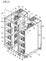
- a plurality of subsidiary units are vertically piled.
- Two housings 2,2 each of which has four chambers 1 piled up are disposed with a space which is a sucking path 3.
- the housings 2,2 have the same shape and size, and the four chambers 1 have the same shape and size.
- the sucking path 3 is closed by a removable inspection door 5 between front walls 4,4 over the housings 2,2.
- the upper part of the sucking path 3 is closed by an operation-display plate 5b.
- the rear end of the sucking path 3 opens, and external air is taken in through the rear opening.
- the side ends of the operation-display plate 5b are mounted with screws to the opposing ends of the housings 2,2, and the operation-display plate 5b can be removed, if required.
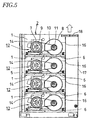
- the inspection door 5 is removable by pushing down a slide latch 5a with a finger to open, so that sucking filters of fluid machines 8 in the housings 2,2 are inspected for maintenance.
- a motor 7 and the fluid machine 8 such as a compressor or a decompression device behind the motor 7 are connected to pulleys 9,10 and a belt 11 to form a fluid machine unit 12.
- a sucking hole 14 is formed through the inner side wall 13 to allow each of the housings 2,2 to communicate with the sucking path 3.
- an exhaust hole 16 is formed in a rear wall 15.
- a tall exhaust duct 17 is provided along the four exhaust holes 16 vertically arranged behind the housing 2.
- An electric exhaust fan 18 is provided in the top wall of the exhaust duct 17.
- the motor 7 and fluid machine 8 in the chamber 1 are cooled with external air, thereby avoiding overheat generated with continuous long-time operation and preventing damage to sliding parts.
- the motor 7 and fluid machine 8 in the chamber 1 can be inspected and maintained by removing a closing plate at the rear end of the sucking path 3 and then removing the inner side wall 13 facing the sucking path.
Landscapes
- Engineering & Computer Science (AREA)
- Mechanical Engineering (AREA)
- General Engineering & Computer Science (AREA)
- Compressors, Vaccum Pumps And Other Relevant Systems (AREA)
- Applications Or Details Of Rotary Compressors (AREA)
- Structures Of Non-Positive Displacement Pumps (AREA)
- Details Of Reciprocating Pumps (AREA)
Applications Claiming Priority (2)
| Application Number | Priority Date | Filing Date | Title |
|---|---|---|---|
| JP2003330494 | 2003-09-22 | ||
| JP2003330494A JP3946678B2 (ja) | 2003-09-22 | 2003-09-22 | パッケージ型流体機械 |
Publications (3)
| Publication Number | Publication Date |
|---|---|
| EP1517043A2 true EP1517043A2 (de) | 2005-03-23 |
| EP1517043A3 EP1517043A3 (de) | 2006-05-03 |
| EP1517043B1 EP1517043B1 (de) | 2008-11-26 |
Family
ID=34191432
Family Applications (1)
| Application Number | Title | Priority Date | Filing Date |
|---|---|---|---|
| EP04022200A Expired - Lifetime EP1517043B1 (de) | 2003-09-22 | 2004-09-17 | Strömungsgerät mit mehreren Einheiten |
Country Status (6)
| Country | Link |
|---|---|
| US (1) | US20050063844A1 (de) |
| EP (1) | EP1517043B1 (de) |
| JP (1) | JP3946678B2 (de) |
| KR (1) | KR100584653B1 (de) |
| CN (1) | CN100371594C (de) |
| DE (1) | DE602004017945D1 (de) |
Cited By (1)
| Publication number | Priority date | Publication date | Assignee | Title |
|---|---|---|---|---|
| CN112449667A (zh) * | 2018-09-13 | 2021-03-05 | 株式会社日立产机系统 | 组合型流体机械 |
Families Citing this family (17)
| Publication number | Priority date | Publication date | Assignee | Title |
|---|---|---|---|---|
| JP5119558B2 (ja) * | 2005-10-03 | 2013-01-16 | オリオン機械株式会社 | 空気圧装置ステーション及び空気圧装置の収納ボックス |
| JP5041849B2 (ja) * | 2007-04-02 | 2012-10-03 | オリオン機械株式会社 | 空気圧装置ステーションの排気温調整システム |
| JP4864798B2 (ja) * | 2007-04-02 | 2012-02-01 | オリオン機械株式会社 | 棚状構造及び空気圧装置収納ボックス |
| CN101776060A (zh) * | 2010-01-20 | 2010-07-14 | 常州亿晶光电科技有限公司 | 太阳能电池自动焊接机真空泵冷却装置 |
| JP5707280B2 (ja) * | 2011-08-24 | 2015-04-22 | 株式会社日立産機システム | パッケージ型圧縮機。 |
| JP5899150B2 (ja) | 2013-04-19 | 2016-04-06 | 株式会社日立産機システム | パッケージ型流体機械 |
| JP5728738B2 (ja) * | 2014-01-08 | 2015-06-03 | オリオン機械株式会社 | パッケージ型の回転ポンプユニット |
| US10072673B2 (en) * | 2014-08-04 | 2018-09-11 | Powerex-Iwata Air Technology, Inc. | Compressor system |
| JP2016145557A (ja) * | 2015-02-09 | 2016-08-12 | アネスト岩田株式会社 | パッケージ型流体機械 |
| EP3306088B1 (de) * | 2015-05-29 | 2020-01-29 | Nabtesco Corporation | Luftkompressionsvorrichtung |
| JP6571422B2 (ja) * | 2015-07-03 | 2019-09-04 | 株式会社神戸製鋼所 | パッケージ型空冷式スクリュー圧縮機 |
| US10704552B2 (en) * | 2016-02-02 | 2020-07-07 | Powerex/Iwata Air Technology Inc. | Vacuum system |
| KR102283382B1 (ko) * | 2017-06-26 | 2021-07-29 | 세메스 주식회사 | 비히클 유지 보수용 승강 장치 |
| USD899463S1 (en) * | 2018-09-12 | 2020-10-20 | Sulzer Management Ag | Compressor |
| JP1689745S (de) * | 2020-11-25 | 2021-07-12 | ||
| GB2700232A (en) * | 2021-09-21 | 2025-12-10 | Scantech Offshore Ltd | Air compressor |
| USD1081728S1 (en) * | 2022-03-30 | 2025-07-01 | Atlas Copco Airpower, Naamloze Vennootschap | Compressor |
Family Cites Families (15)
| Publication number | Priority date | Publication date | Assignee | Title |
|---|---|---|---|---|
| FR1078545A (fr) * | 1953-03-30 | 1954-11-18 | Fabrications Ind Pour Le Chauf | Appareil à ventilateur destiné en particulier au conditionnement d'air des locaux et installation de chauffage réalisée à l'aide de cet appareil |
| US3242686A (en) * | 1964-10-20 | 1966-03-29 | Clark Equipment Co | Unitary machine room |
| US4007874A (en) * | 1975-08-14 | 1977-02-15 | Wilbert Laudner | Heating system |
| JPH0249458A (ja) * | 1988-08-11 | 1990-02-19 | Hitachi Ltd | Lsiの冷却水供給装置 |
| JPH07113359B2 (ja) * | 1989-08-19 | 1995-12-06 | トキコ株式会社 | 圧縮機 |
| US5688169A (en) * | 1996-03-06 | 1997-11-18 | Lucent Technologies Inc. | Electrical equipment cabinet cooling |
| US6000623A (en) * | 1998-01-15 | 1999-12-14 | International Business Machines Corporation | System packaging for high performance computer applications |
| JP4077921B2 (ja) | 1998-02-19 | 2008-04-23 | 株式会社日立製作所 | 空気圧縮機 |
| JP2002291919A (ja) * | 2001-03-30 | 2002-10-08 | Nec Corp | 電子機器の防火方式 |
| JP4014128B2 (ja) | 2001-07-26 | 2007-11-28 | デンヨー株式会社 | 空気圧縮機 |
| US6672955B2 (en) * | 2001-09-07 | 2004-01-06 | International Business Machines Corporation | Air flow management system for an internet data center |
| US6594148B1 (en) * | 2002-01-16 | 2003-07-15 | Cisco Technology, Inc. | Airflow system |
| KR100508140B1 (ko) * | 2002-06-28 | 2005-08-10 | 가부시끼가이샤 히다치 세이사꾸쇼 | 패키지형 압축기 |
| US6611428B1 (en) * | 2002-08-12 | 2003-08-26 | Motorola, Inc. | Cabinet for cooling electronic modules |
| US20060172685A1 (en) * | 2004-08-26 | 2006-08-03 | O'brien Paul | Internal environmental control system and uses thereof |
-
2003
- 2003-09-22 JP JP2003330494A patent/JP3946678B2/ja not_active Expired - Fee Related
-
2004
- 2004-09-15 US US10/941,574 patent/US20050063844A1/en not_active Abandoned
- 2004-09-17 DE DE602004017945T patent/DE602004017945D1/de not_active Expired - Fee Related
- 2004-09-17 CN CNB2004100744963A patent/CN100371594C/zh not_active Expired - Fee Related
- 2004-09-17 EP EP04022200A patent/EP1517043B1/de not_active Expired - Lifetime
- 2004-09-20 KR KR1020040075002A patent/KR100584653B1/ko not_active Expired - Lifetime
Cited By (3)
| Publication number | Priority date | Publication date | Assignee | Title |
|---|---|---|---|---|
| CN112449667A (zh) * | 2018-09-13 | 2021-03-05 | 株式会社日立产机系统 | 组合型流体机械 |
| EP3851673A4 (de) * | 2018-09-13 | 2022-03-09 | Hitachi Industrial Equipment Systems Co., Ltd. | Paketartige strömungsmaschine |
| US11898544B2 (en) | 2018-09-13 | 2024-02-13 | Hitachi Industrial Equipment Systems Co., Ltd. | Package type fluid machine |
Also Published As
| Publication number | Publication date |
|---|---|
| EP1517043B1 (de) | 2008-11-26 |
| JP3946678B2 (ja) | 2007-07-18 |
| US20050063844A1 (en) | 2005-03-24 |
| KR20050029691A (ko) | 2005-03-28 |
| EP1517043A3 (de) | 2006-05-03 |
| CN100371594C (zh) | 2008-02-27 |
| KR100584653B1 (ko) | 2006-05-30 |
| DE602004017945D1 (de) | 2009-01-08 |
| CN1601082A (zh) | 2005-03-30 |
| JP2005098147A (ja) | 2005-04-14 |
Similar Documents
| Publication | Publication Date | Title |
|---|---|---|
| EP1517043B1 (de) | Strömungsgerät mit mehreren Einheiten | |
| CN104110364B (zh) | 箱式流体机械 | |
| US9541088B2 (en) | Evacuation apparatus | |
| US10309700B2 (en) | High pressure compressor and refrigerating machine having a high pressure compressor | |
| US6439865B1 (en) | Vacuum pump | |
| JP2008255799A (ja) | ロータリコンプレッサ及びその運転制御方法 | |
| JP4255765B2 (ja) | パッケージ形圧縮機 | |
| KR100837143B1 (ko) | 패키지형 압축기 | |
| US20040115063A1 (en) | Scroll compressor | |
| KR20180008217A (ko) | 유체기계용 공랭식 냉각장치 | |
| JP5433611B2 (ja) | パッケージ型圧縮機 | |
| JP2012524204A (ja) | 容積形ポンプのための粗引き法 | |
| US11326598B2 (en) | Compressor | |
| JP5412243B2 (ja) | ブースタ圧縮機 | |
| JP2008111417A (ja) | 空気圧縮装置 | |
| JP2007332788A (ja) | パッケージ形圧縮機 | |
| JPH0571472A (ja) | 気体圧縮機 | |
| KR100414122B1 (ko) | 압축기용 소음저감케이스 | |
| CN112292529A (zh) | 箱式流体机械 | |
| JPH04148088A (ja) | 密閉形圧縮機 | |
| WO2011125681A1 (ja) | 電動機一体型ブースター圧縮機 | |
| JP2976231B2 (ja) | 圧縮機 | |
| JP2012122487A (ja) | エアドライヤ搭載形パッケージ形圧縮機 | |
| JP2013167251A (ja) | ブースタ圧縮機 | |
| CN108374788A (zh) | 一种变排量式涡旋压缩机 |
Legal Events
| Date | Code | Title | Description |
|---|---|---|---|
| PUAI | Public reference made under article 153(3) epc to a published international application that has entered the european phase |
Free format text: ORIGINAL CODE: 0009012 |
|
| 17P | Request for examination filed |
Effective date: 20040917 |
|
| AK | Designated contracting states |
Kind code of ref document: A2 Designated state(s): AT BE BG CH CY CZ DE DK EE ES FI FR GB GR HU IE IT LI LU MC NL PL PT RO SE SI SK TR |
|
| AX | Request for extension of the european patent |
Extension state: AL HR LT LV MK |
|
| PUAL | Search report despatched |
Free format text: ORIGINAL CODE: 0009013 |
|
| AK | Designated contracting states |
Kind code of ref document: A3 Designated state(s): AT BE BG CH CY CZ DE DK EE ES FI FR GB GR HU IE IT LI LU MC NL PL PT RO SE SI SK TR |
|
| AX | Request for extension of the european patent |
Extension state: AL HR LT LV MK |
|
| AKX | Designation fees paid |
Designated state(s): BE DE FR IT |
|
| 17Q | First examination report despatched |
Effective date: 20070323 |
|
| GRAP | Despatch of communication of intention to grant a patent |
Free format text: ORIGINAL CODE: EPIDOSNIGR1 |
|
| GRAS | Grant fee paid |
Free format text: ORIGINAL CODE: EPIDOSNIGR3 |
|
| GRAA | (expected) grant |
Free format text: ORIGINAL CODE: 0009210 |
|
| AK | Designated contracting states |
Kind code of ref document: B1 Designated state(s): BE DE FR IT |
|
| REF | Corresponds to: |
Ref document number: 602004017945 Country of ref document: DE Date of ref document: 20090108 Kind code of ref document: P |
|
| PLBE | No opposition filed within time limit |
Free format text: ORIGINAL CODE: 0009261 |
|
| STAA | Information on the status of an ep patent application or granted ep patent |
Free format text: STATUS: NO OPPOSITION FILED WITHIN TIME LIMIT |
|
| 26N | No opposition filed |
Effective date: 20090827 |
|
| REG | Reference to a national code |
Ref country code: FR Ref legal event code: ST Effective date: 20100531 |
|
| PG25 | Lapsed in a contracting state [announced via postgrant information from national office to epo] |
Ref country code: FR Free format text: LAPSE BECAUSE OF NON-PAYMENT OF DUE FEES Effective date: 20090930 Ref country code: DE Free format text: LAPSE BECAUSE OF NON-PAYMENT OF DUE FEES Effective date: 20100401 |
|
| PG25 | Lapsed in a contracting state [announced via postgrant information from national office to epo] |
Ref country code: IT Free format text: LAPSE BECAUSE OF NON-PAYMENT OF DUE FEES Effective date: 20090917 |
|
| PGFP | Annual fee paid to national office [announced via postgrant information from national office to epo] |
Ref country code: BE Payment date: 20170921 Year of fee payment: 14 |
|
| REG | Reference to a national code |
Ref country code: BE Ref legal event code: MM Effective date: 20180930 |
|
| PG25 | Lapsed in a contracting state [announced via postgrant information from national office to epo] |
Ref country code: BE Free format text: LAPSE BECAUSE OF NON-PAYMENT OF DUE FEES Effective date: 20180930 |