EP1517043B1 - Strömungsgerät mit mehreren Einheiten - Google Patents
Strömungsgerät mit mehreren Einheiten Download PDFInfo
- Publication number
- EP1517043B1 EP1517043B1 EP04022200A EP04022200A EP1517043B1 EP 1517043 B1 EP1517043 B1 EP 1517043B1 EP 04022200 A EP04022200 A EP 04022200A EP 04022200 A EP04022200 A EP 04022200A EP 1517043 B1 EP1517043 B1 EP 1517043B1
- Authority
- EP
- European Patent Office
- Prior art keywords
- housings
- exhaust
- package
- chambers
- sucking
- Prior art date
- Legal status (The legal status is an assumption and is not a legal conclusion. Google has not performed a legal analysis and makes no representation as to the accuracy of the status listed.)
- Expired - Lifetime
Links
- 239000012530 fluid Substances 0.000 claims description 11
- 238000007689 inspection Methods 0.000 claims description 6
- 238000012423 maintenance Methods 0.000 claims description 5
- 238000001816 cooling Methods 0.000 claims 1
- 230000007423 decrease Effects 0.000 description 8
- 230000006835 compression Effects 0.000 description 4
- 238000007906 compression Methods 0.000 description 4
- 230000002411 adverse Effects 0.000 description 1
- 239000000498 cooling water Substances 0.000 description 1
- 230000006837 decompression Effects 0.000 description 1
- 230000000694 effects Effects 0.000 description 1
- 238000009434 installation Methods 0.000 description 1
- 238000012986 modification Methods 0.000 description 1
- 230000004048 modification Effects 0.000 description 1
- 230000001131 transforming effect Effects 0.000 description 1
Images


Classifications
-
- F—MECHANICAL ENGINEERING; LIGHTING; HEATING; WEAPONS; BLASTING
- F04—POSITIVE - DISPLACEMENT MACHINES FOR LIQUIDS; PUMPS FOR LIQUIDS OR ELASTIC FLUIDS
- F04B—POSITIVE-DISPLACEMENT MACHINES FOR LIQUIDS; PUMPS
- F04B23/00—Pumping installations or systems
- F04B23/04—Combinations of two or more pumps
-
- F—MECHANICAL ENGINEERING; LIGHTING; HEATING; WEAPONS; BLASTING
- F01—MACHINES OR ENGINES IN GENERAL; ENGINE PLANTS IN GENERAL; STEAM ENGINES
- F01C—ROTARY-PISTON OR OSCILLATING-PISTON MACHINES OR ENGINES
- F01C21/00—Component parts, details or accessories not provided for in groups F01C1/00 - F01C20/00
- F01C21/007—General arrangements of parts; Frames and supporting elements
-
- F—MECHANICAL ENGINEERING; LIGHTING; HEATING; WEAPONS; BLASTING
- F04—POSITIVE - DISPLACEMENT MACHINES FOR LIQUIDS; PUMPS FOR LIQUIDS OR ELASTIC FLUIDS
- F04C—ROTARY-PISTON, OR OSCILLATING-PISTON, POSITIVE-DISPLACEMENT MACHINES FOR LIQUIDS; ROTARY-PISTON, OR OSCILLATING-PISTON, POSITIVE-DISPLACEMENT PUMPS
- F04C23/00—Combinations of two or more pumps, each being of rotary-piston or oscillating-piston type, specially adapted for elastic fluids; Pumping installations specially adapted for elastic fluids; Multi-stage pumps specially adapted for elastic fluids
- F04C23/001—Combinations of two or more pumps, each being of rotary-piston or oscillating-piston type, specially adapted for elastic fluids; Pumping installations specially adapted for elastic fluids; Multi-stage pumps specially adapted for elastic fluids of similar working principle
-
- F—MECHANICAL ENGINEERING; LIGHTING; HEATING; WEAPONS; BLASTING
- F04—POSITIVE - DISPLACEMENT MACHINES FOR LIQUIDS; PUMPS FOR LIQUIDS OR ELASTIC FLUIDS
- F04C—ROTARY-PISTON, OR OSCILLATING-PISTON, POSITIVE-DISPLACEMENT MACHINES FOR LIQUIDS; ROTARY-PISTON, OR OSCILLATING-PISTON, POSITIVE-DISPLACEMENT PUMPS
- F04C29/00—Component parts, details or accessories of pumps or pumping installations, not provided for in groups F04C18/00 - F04C28/00
- F04C29/04—Heating; Cooling; Heat insulation
Definitions
- the present invention relates to a package-type fluidic apparatus in which a fluid machine such as a scroll compressor, a vacuum pump, an expander or a blower is connected to a drive source.
- a fluid machine such as a scroll compressor, a vacuum pump, an expander or a blower is connected to a drive source.
- a single high-output compressor is included within the package, or a plurality of low-output compressors are piled up to form a high-output compressor in a package.
- a plurality of compressors such as four are piled up to constitute a single package compressor, an example of such a single package compressor is given in XP 007900119.
- XP 007900119 When it operates with about 100 % of compression air, all the four compressors operate.
- One of the four stops with about 70 % of air consumption; two stop with less than 50 %; three stop with further decrease; and all stop with further decrease.
- electric power consumption is corresponding to the compression air consumption.
- Electric power consumption decreases compared with a single high-output compressor. If the compressor stops owing to any cause, capability for producing compression air becomes null immediately in the single high-output compressor to result in stop of all machines in which compression air is used, thereby increasing damage in the factory.
- a plurality of compressors even if one stops, it will avoid the risk that operation completely stops, as the others continue to operate.
- a plurality of compressors may preferably be employed.
- a compressor and its drive source form a set of subsidiary unit.
- a required area increases to unable its location.
- a plurality of subsidiary units are vertically piled.
- JP 02-049458 discloses a cooling water supply device wherein two stacked units are placed on the opposite sides of a common duct-shaped path for the exhaust air flow.
- One embodiment of this document shows independent air inlets placed on the respective sides of the housings.
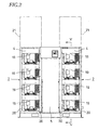
- Two housings 2,2 each of which has four chambers 1 piled up are disposed with a space which is a sucking path 3.
- the housings 2,2 have the same shape and size, and the four chambers 1 have the same shape and size.
- the sucking path 3 is closed by a removable inspection door 5 between front walls 4,4 over the housings 2,2.
- the upper part of the sucking path 3 is closed by an operation-display plate 5b.
- the rear end of the sucking path 3 opens, and external air is taken in through the rear opening.
- the side ends of the operation-display plate 5b are mounted with screws to the opposing ends of the housings 2,2, and the operation-display plate 5b can be removed, if required.
- the inspection door 5 is removable by pushing down a slide latch 5a with a finger to open, so that sucking filters of fluid machines 8 in the housings 2,2 are inspected for maintenance.
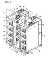
- a motor 7 and the fluid machine 8 such as a compressor or a decompression device behind the motor 7 are connected to pulleys 9,10 and a belt 11 to form a fluid machine unit 12.
- a sucking hole 14 is formed through the inner side wall 13 to allow each of the housings 2,2 to communicate with the sucking path 3.
- an exhaust hole 16 is formed in a rear wall 15.
- a tall exhaust duct 17 is provided along the four exhaust holes 16 vertically arranged behind the housing 2.
- An electric exhaust fan 18 is provided in the top wall of the exhaust duct 17.
- the motor 7 and fluid machine 8 in the chamber 1 are cooled with external air, thereby avoiding overheat generated with continuous long-time operation and preventing damage to sliding parts.
- the motor 7 and fluid machine 8 in the chamber 1 can be inspected and maintained by removing a closing plate at the rear end of the sucking path 3 and then removing the inner side wall 13 facing the sucking path.
Landscapes
- Engineering & Computer Science (AREA)
- Mechanical Engineering (AREA)
- General Engineering & Computer Science (AREA)
- Compressors, Vaccum Pumps And Other Relevant Systems (AREA)
- Applications Or Details Of Rotary Compressors (AREA)
- Structures Of Non-Positive Displacement Pumps (AREA)
- Details Of Reciprocating Pumps (AREA)
Claims (3)
- Strömungsgerät mit mehreren Einheiten, umfassend zwei Gehäuse (2, 2), jedes davon umfassend eine Vielzahl von darin gestapelten Kammern (1), einen Auslasskanal (17), bereitgestellt an einer rückseitigen Wand jedes der Gehäuse (2, 2), wobei jede der Kammern (1) eine Auslassöffnung (16) und eine Strömungsgeräteeinheit aufweist, bei welcher ein Strömungsgerät mit einer Antriebsquelle verbunden ist, wobei der Auslasskanal (17) mit den Auslassöffnungen (16) der Kammern (1) verbunden ist, sowie einen Ansaugkanal (3) zwischen den zwei Gehäusen (2, 2), dadurch gekennzeichnet, dass:jede der Kammern (1) eine Ansaugöffnung (14) aufweist, ausgebildet in einer inneren Seitenwand, wobei sich der Ansaugkanal (3) an einem rückseitigen Ende zwischen den Gehäusen (2, 2) öffnet und auf beiden Seiten einen seitlichen Zugang zu den Strömungsgeräten zu Zwecken der Wartung und Inspektion erlaubt, wobei jeder der Auslasskanäle (17) einen Absaugventilator (18) aufweist, um es der Luft in jeder der Kammern (1), welche über den Ansaugkanal (3) und die Ansaugöffnung (14) angesaugt wurde, zu ermöglichen, nach außen über die Auslassöffnungen (16) und die Auslasskanäle (17) abgeleitet zu werden, wodurch die Kühlwirkung auf die Strömungsgeräteeinheit erhöht wird.
- Strömungsgerät mit mehreren Einheiten nach Anspruch 1, wobei die zwei Gehäuse (2, 2) im Wesentlichen die gleiche Form und Größe aufweisen.
- Strömungsgerät mit mehreren Einheiten nach Anspruch 1, wobei ein frontseitiges Ende des Ansaugkanals (3) verschlossen ist mittels einer Betriebsanzeigetafel (5b) und einer abnehmbaren Inspektionsluke (5) zwischen den Gehäusen (2, 2).
Applications Claiming Priority (2)
| Application Number | Priority Date | Filing Date | Title |
|---|---|---|---|
| JP2003330494 | 2003-09-22 | ||
| JP2003330494A JP3946678B2 (ja) | 2003-09-22 | 2003-09-22 | パッケージ型流体機械 |
Publications (3)
| Publication Number | Publication Date |
|---|---|
| EP1517043A2 EP1517043A2 (de) | 2005-03-23 |
| EP1517043A3 EP1517043A3 (de) | 2006-05-03 |
| EP1517043B1 true EP1517043B1 (de) | 2008-11-26 |
Family
ID=34191432
Family Applications (1)
| Application Number | Title | Priority Date | Filing Date |
|---|---|---|---|
| EP04022200A Expired - Lifetime EP1517043B1 (de) | 2003-09-22 | 2004-09-17 | Strömungsgerät mit mehreren Einheiten |
Country Status (6)
| Country | Link |
|---|---|
| US (1) | US20050063844A1 (de) |
| EP (1) | EP1517043B1 (de) |
| JP (1) | JP3946678B2 (de) |
| KR (1) | KR100584653B1 (de) |
| CN (1) | CN100371594C (de) |
| DE (1) | DE602004017945D1 (de) |
Cited By (1)
| Publication number | Priority date | Publication date | Assignee | Title |
|---|---|---|---|---|
| WO2023047095A1 (en) * | 2021-09-21 | 2023-03-30 | Scantech Offshore Limited | Air compressor |
Families Citing this family (17)
| Publication number | Priority date | Publication date | Assignee | Title |
|---|---|---|---|---|
| JP5119558B2 (ja) * | 2005-10-03 | 2013-01-16 | オリオン機械株式会社 | 空気圧装置ステーション及び空気圧装置の収納ボックス |
| JP5041849B2 (ja) * | 2007-04-02 | 2012-10-03 | オリオン機械株式会社 | 空気圧装置ステーションの排気温調整システム |
| JP4864798B2 (ja) * | 2007-04-02 | 2012-02-01 | オリオン機械株式会社 | 棚状構造及び空気圧装置収納ボックス |
| CN101776060A (zh) * | 2010-01-20 | 2010-07-14 | 常州亿晶光电科技有限公司 | 太阳能电池自动焊接机真空泵冷却装置 |
| JP5707280B2 (ja) * | 2011-08-24 | 2015-04-22 | 株式会社日立産機システム | パッケージ型圧縮機。 |
| JP5899150B2 (ja) | 2013-04-19 | 2016-04-06 | 株式会社日立産機システム | パッケージ型流体機械 |
| JP5728738B2 (ja) * | 2014-01-08 | 2015-06-03 | オリオン機械株式会社 | パッケージ型の回転ポンプユニット |
| US10072673B2 (en) * | 2014-08-04 | 2018-09-11 | Powerex-Iwata Air Technology, Inc. | Compressor system |
| JP2016145557A (ja) * | 2015-02-09 | 2016-08-12 | アネスト岩田株式会社 | パッケージ型流体機械 |
| EP3306088B1 (de) * | 2015-05-29 | 2020-01-29 | Nabtesco Corporation | Luftkompressionsvorrichtung |
| JP6571422B2 (ja) * | 2015-07-03 | 2019-09-04 | 株式会社神戸製鋼所 | パッケージ型空冷式スクリュー圧縮機 |
| US10704552B2 (en) * | 2016-02-02 | 2020-07-07 | Powerex/Iwata Air Technology Inc. | Vacuum system |
| KR102283382B1 (ko) * | 2017-06-26 | 2021-07-29 | 세메스 주식회사 | 비히클 유지 보수용 승강 장치 |
| USD899463S1 (en) * | 2018-09-12 | 2020-10-20 | Sulzer Management Ag | Compressor |
| EP3851673B1 (de) * | 2018-09-13 | 2023-11-22 | Hitachi Industrial Equipment Systems Co., Ltd. | Paketartige strömungsmaschine |
| JP1689745S (de) * | 2020-11-25 | 2021-07-12 | ||
| USD1081728S1 (en) * | 2022-03-30 | 2025-07-01 | Atlas Copco Airpower, Naamloze Vennootschap | Compressor |
Family Cites Families (15)
| Publication number | Priority date | Publication date | Assignee | Title |
|---|---|---|---|---|
| FR1078545A (fr) * | 1953-03-30 | 1954-11-18 | Fabrications Ind Pour Le Chauf | Appareil à ventilateur destiné en particulier au conditionnement d'air des locaux et installation de chauffage réalisée à l'aide de cet appareil |
| US3242686A (en) * | 1964-10-20 | 1966-03-29 | Clark Equipment Co | Unitary machine room |
| US4007874A (en) * | 1975-08-14 | 1977-02-15 | Wilbert Laudner | Heating system |
| JPH0249458A (ja) * | 1988-08-11 | 1990-02-19 | Hitachi Ltd | Lsiの冷却水供給装置 |
| JPH07113359B2 (ja) * | 1989-08-19 | 1995-12-06 | トキコ株式会社 | 圧縮機 |
| US5688169A (en) * | 1996-03-06 | 1997-11-18 | Lucent Technologies Inc. | Electrical equipment cabinet cooling |
| US6000623A (en) * | 1998-01-15 | 1999-12-14 | International Business Machines Corporation | System packaging for high performance computer applications |
| JP4077921B2 (ja) | 1998-02-19 | 2008-04-23 | 株式会社日立製作所 | 空気圧縮機 |
| JP2002291919A (ja) * | 2001-03-30 | 2002-10-08 | Nec Corp | 電子機器の防火方式 |
| JP4014128B2 (ja) | 2001-07-26 | 2007-11-28 | デンヨー株式会社 | 空気圧縮機 |
| US6672955B2 (en) * | 2001-09-07 | 2004-01-06 | International Business Machines Corporation | Air flow management system for an internet data center |
| US6594148B1 (en) * | 2002-01-16 | 2003-07-15 | Cisco Technology, Inc. | Airflow system |
| KR100508140B1 (ko) * | 2002-06-28 | 2005-08-10 | 가부시끼가이샤 히다치 세이사꾸쇼 | 패키지형 압축기 |
| US6611428B1 (en) * | 2002-08-12 | 2003-08-26 | Motorola, Inc. | Cabinet for cooling electronic modules |
| US20060172685A1 (en) * | 2004-08-26 | 2006-08-03 | O'brien Paul | Internal environmental control system and uses thereof |
-
2003
- 2003-09-22 JP JP2003330494A patent/JP3946678B2/ja not_active Expired - Fee Related
-
2004
- 2004-09-15 US US10/941,574 patent/US20050063844A1/en not_active Abandoned
- 2004-09-17 DE DE602004017945T patent/DE602004017945D1/de not_active Expired - Fee Related
- 2004-09-17 CN CNB2004100744963A patent/CN100371594C/zh not_active Expired - Fee Related
- 2004-09-17 EP EP04022200A patent/EP1517043B1/de not_active Expired - Lifetime
- 2004-09-20 KR KR1020040075002A patent/KR100584653B1/ko not_active Expired - Lifetime
Cited By (2)
| Publication number | Priority date | Publication date | Assignee | Title |
|---|---|---|---|---|
| WO2023047095A1 (en) * | 2021-09-21 | 2023-03-30 | Scantech Offshore Limited | Air compressor |
| AU2022349846B2 (en) * | 2021-09-21 | 2025-10-09 | Scantech Offshore Limited | Air compressor |
Also Published As
| Publication number | Publication date |
|---|---|
| JP3946678B2 (ja) | 2007-07-18 |
| EP1517043A2 (de) | 2005-03-23 |
| US20050063844A1 (en) | 2005-03-24 |
| KR20050029691A (ko) | 2005-03-28 |
| EP1517043A3 (de) | 2006-05-03 |
| CN100371594C (zh) | 2008-02-27 |
| KR100584653B1 (ko) | 2006-05-30 |
| DE602004017945D1 (de) | 2009-01-08 |
| CN1601082A (zh) | 2005-03-30 |
| JP2005098147A (ja) | 2005-04-14 |
Similar Documents
| Publication | Publication Date | Title |
|---|---|---|
| EP1517043B1 (de) | Strömungsgerät mit mehreren Einheiten | |
| CN104110364B (zh) | 箱式流体机械 | |
| US11473582B2 (en) | Package-type compressor | |
| JP5205041B2 (ja) | 空気圧縮機 | |
| KR101969485B1 (ko) | 임펠러수단냉각팬이 형성된 연료전지용 터보 송풍기 | |
| RU2581554C2 (ru) | Наружный блок охлаждающего устройства | |
| CN111727321A (zh) | 流体机械 | |
| EP3258110A1 (de) | Paketfluidmaschine | |
| JP4255765B2 (ja) | パッケージ形圧縮機 | |
| KR100837143B1 (ko) | 패키지형 압축기 | |
| KR102592232B1 (ko) | 유체기계용 공랭식 냉각장치 | |
| JP4996142B2 (ja) | パッケージ形圧縮機 | |
| CN218062612U (zh) | 气体压缩组件 | |
| JP2008111417A (ja) | 空気圧縮装置 | |
| JPWO2019077979A1 (ja) | 圧縮機 | |
| CN102052285A (zh) | 增压压缩机 | |
| EP3851672A1 (de) | Paketfluidmaschine | |
| KR20230066824A (ko) | 터보 블로워 패키지 | |
| CN100404868C (zh) | 流体环气泵 | |
| JP2944488B2 (ja) | パッケージ形油冷式空気圧縮機 | |
| JP2012122487A (ja) | エアドライヤ搭載形パッケージ形圧縮機 | |
| JP2013167251A (ja) | ブースタ圧縮機 | |
| JPH06241501A (ja) | 空気調和機の室外ユニット |
Legal Events
| Date | Code | Title | Description |
|---|---|---|---|
| PUAI | Public reference made under article 153(3) epc to a published international application that has entered the european phase |
Free format text: ORIGINAL CODE: 0009012 |
|
| 17P | Request for examination filed |
Effective date: 20040917 |
|
| AK | Designated contracting states |
Kind code of ref document: A2 Designated state(s): AT BE BG CH CY CZ DE DK EE ES FI FR GB GR HU IE IT LI LU MC NL PL PT RO SE SI SK TR |
|
| AX | Request for extension of the european patent |
Extension state: AL HR LT LV MK |
|
| PUAL | Search report despatched |
Free format text: ORIGINAL CODE: 0009013 |
|
| AK | Designated contracting states |
Kind code of ref document: A3 Designated state(s): AT BE BG CH CY CZ DE DK EE ES FI FR GB GR HU IE IT LI LU MC NL PL PT RO SE SI SK TR |
|
| AX | Request for extension of the european patent |
Extension state: AL HR LT LV MK |
|
| AKX | Designation fees paid |
Designated state(s): BE DE FR IT |
|
| 17Q | First examination report despatched |
Effective date: 20070323 |
|
| GRAP | Despatch of communication of intention to grant a patent |
Free format text: ORIGINAL CODE: EPIDOSNIGR1 |
|
| GRAS | Grant fee paid |
Free format text: ORIGINAL CODE: EPIDOSNIGR3 |
|
| GRAA | (expected) grant |
Free format text: ORIGINAL CODE: 0009210 |
|
| AK | Designated contracting states |
Kind code of ref document: B1 Designated state(s): BE DE FR IT |
|
| REF | Corresponds to: |
Ref document number: 602004017945 Country of ref document: DE Date of ref document: 20090108 Kind code of ref document: P |
|
| PLBE | No opposition filed within time limit |
Free format text: ORIGINAL CODE: 0009261 |
|
| STAA | Information on the status of an ep patent application or granted ep patent |
Free format text: STATUS: NO OPPOSITION FILED WITHIN TIME LIMIT |
|
| 26N | No opposition filed |
Effective date: 20090827 |
|
| REG | Reference to a national code |
Ref country code: FR Ref legal event code: ST Effective date: 20100531 |
|
| PG25 | Lapsed in a contracting state [announced via postgrant information from national office to epo] |
Ref country code: FR Free format text: LAPSE BECAUSE OF NON-PAYMENT OF DUE FEES Effective date: 20090930 Ref country code: DE Free format text: LAPSE BECAUSE OF NON-PAYMENT OF DUE FEES Effective date: 20100401 |
|
| PG25 | Lapsed in a contracting state [announced via postgrant information from national office to epo] |
Ref country code: IT Free format text: LAPSE BECAUSE OF NON-PAYMENT OF DUE FEES Effective date: 20090917 |
|
| PGFP | Annual fee paid to national office [announced via postgrant information from national office to epo] |
Ref country code: BE Payment date: 20170921 Year of fee payment: 14 |
|
| REG | Reference to a national code |
Ref country code: BE Ref legal event code: MM Effective date: 20180930 |
|
| PG25 | Lapsed in a contracting state [announced via postgrant information from national office to epo] |
Ref country code: BE Free format text: LAPSE BECAUSE OF NON-PAYMENT OF DUE FEES Effective date: 20180930 |