EP1517024A1 - Kraftstoffseifgenschaften Bestimmungsvorrichtung - Google Patents
Kraftstoffseifgenschaften Bestimmungsvorrichtung Download PDFInfo
- Publication number
- EP1517024A1 EP1517024A1 EP04021387A EP04021387A EP1517024A1 EP 1517024 A1 EP1517024 A1 EP 1517024A1 EP 04021387 A EP04021387 A EP 04021387A EP 04021387 A EP04021387 A EP 04021387A EP 1517024 A1 EP1517024 A1 EP 1517024A1
- Authority
- EP
- European Patent Office
- Prior art keywords
- fuel
- cylinder
- fuel property
- engine
- property determination
- Prior art date
- Legal status (The legal status is an assumption and is not a legal conclusion. Google has not performed a legal analysis and makes no representation as to the accuracy of the status listed.)
- Granted
Links
- 239000000446 fuel Substances 0.000 title claims abstract description 359
- 238000002347 injection Methods 0.000 claims abstract description 91
- 239000007924 injection Substances 0.000 claims abstract description 91
- 230000008859 change Effects 0.000 claims abstract description 61
- 238000002485 combustion reaction Methods 0.000 claims abstract description 41
- 239000000498 cooling water Substances 0.000 claims description 30
- 238000000034 method Methods 0.000 claims description 5
- 230000005484 gravity Effects 0.000 claims description 2
- 230000001133 acceleration Effects 0.000 description 17
- 230000006835 compression Effects 0.000 description 5
- 238000007906 compression Methods 0.000 description 5
- 238000010276 construction Methods 0.000 description 5
- XLYOFNOQVPJJNP-UHFFFAOYSA-N water Substances O XLYOFNOQVPJJNP-UHFFFAOYSA-N 0.000 description 5
- 230000007423 decrease Effects 0.000 description 3
- 238000001514 detection method Methods 0.000 description 3
- 230000008016 vaporization Effects 0.000 description 3
- 230000003247 decreasing effect Effects 0.000 description 2
- 238000003745 diagnosis Methods 0.000 description 2
- 230000004044 response Effects 0.000 description 2
- 238000005070 sampling Methods 0.000 description 2
- 238000011144 upstream manufacturing Methods 0.000 description 2
- 238000009834 vaporization Methods 0.000 description 2
- 230000015556 catabolic process Effects 0.000 description 1
- 238000006731 degradation reaction Methods 0.000 description 1
- 230000001934 delay Effects 0.000 description 1
- 238000012986 modification Methods 0.000 description 1
- 230000004048 modification Effects 0.000 description 1
- 230000008569 process Effects 0.000 description 1
- 230000001360 synchronised effect Effects 0.000 description 1
Images






Classifications
-
- F—MECHANICAL ENGINEERING; LIGHTING; HEATING; WEAPONS; BLASTING
- F02—COMBUSTION ENGINES; HOT-GAS OR COMBUSTION-PRODUCT ENGINE PLANTS
- F02D—CONTROLLING COMBUSTION ENGINES
- F02D33/00—Controlling delivery of fuel or combustion-air, not otherwise provided for
- F02D33/003—Controlling the feeding of liquid fuel from storage containers to carburettors or fuel-injection apparatus ; Failure or leakage prevention; Diagnosis or detection of failure; Arrangement of sensors in the fuel system; Electric wiring; Electrostatic discharge
-
- F—MECHANICAL ENGINEERING; LIGHTING; HEATING; WEAPONS; BLASTING
- F02—COMBUSTION ENGINES; HOT-GAS OR COMBUSTION-PRODUCT ENGINE PLANTS
- F02D—CONTROLLING COMBUSTION ENGINES
- F02D19/00—Controlling engines characterised by their use of non-liquid fuels, pluralities of fuels, or non-fuel substances added to the combustible mixtures
- F02D19/06—Controlling engines characterised by their use of non-liquid fuels, pluralities of fuels, or non-fuel substances added to the combustible mixtures peculiar to engines working with pluralities of fuels, e.g. alternatively with light and heavy fuel oil, other than engines indifferent to the fuel consumed
- F02D19/0639—Controlling engines characterised by their use of non-liquid fuels, pluralities of fuels, or non-fuel substances added to the combustible mixtures peculiar to engines working with pluralities of fuels, e.g. alternatively with light and heavy fuel oil, other than engines indifferent to the fuel consumed characterised by the type of fuels
- F02D19/0649—Liquid fuels having different boiling temperatures, volatilities, densities, viscosities, cetane or octane numbers
- F02D19/0657—Heavy or light fuel oils; Fuels characterised by their impurities such as sulfur content or differences in grade, e.g. for ships
-
- F—MECHANICAL ENGINEERING; LIGHTING; HEATING; WEAPONS; BLASTING
- F02—COMBUSTION ENGINES; HOT-GAS OR COMBUSTION-PRODUCT ENGINE PLANTS
- F02D—CONTROLLING COMBUSTION ENGINES
- F02D19/00—Controlling engines characterised by their use of non-liquid fuels, pluralities of fuels, or non-fuel substances added to the combustible mixtures
- F02D19/06—Controlling engines characterised by their use of non-liquid fuels, pluralities of fuels, or non-fuel substances added to the combustible mixtures peculiar to engines working with pluralities of fuels, e.g. alternatively with light and heavy fuel oil, other than engines indifferent to the fuel consumed
- F02D19/08—Controlling engines characterised by their use of non-liquid fuels, pluralities of fuels, or non-fuel substances added to the combustible mixtures peculiar to engines working with pluralities of fuels, e.g. alternatively with light and heavy fuel oil, other than engines indifferent to the fuel consumed simultaneously using pluralities of fuels
- F02D19/082—Premixed fuels, i.e. emulsions or blends
- F02D19/085—Control based on the fuel type or composition
- F02D19/087—Control based on the fuel type or composition with determination of densities, viscosities, composition, concentration or mixture ratios of fuels
- F02D19/088—Control based on the fuel type or composition with determination of densities, viscosities, composition, concentration or mixture ratios of fuels by estimation, i.e. without using direct measurements of a corresponding sensor
-
- F—MECHANICAL ENGINEERING; LIGHTING; HEATING; WEAPONS; BLASTING
- F02—COMBUSTION ENGINES; HOT-GAS OR COMBUSTION-PRODUCT ENGINE PLANTS
- F02D—CONTROLLING COMBUSTION ENGINES
- F02D41/00—Electrical control of supply of combustible mixture or its constituents
- F02D41/02—Circuit arrangements for generating control signals
- F02D41/04—Introducing corrections for particular operating conditions
- F02D41/06—Introducing corrections for particular operating conditions for engine starting or warming up
- F02D41/062—Introducing corrections for particular operating conditions for engine starting or warming up for starting
-
- F—MECHANICAL ENGINEERING; LIGHTING; HEATING; WEAPONS; BLASTING
- F02—COMBUSTION ENGINES; HOT-GAS OR COMBUSTION-PRODUCT ENGINE PLANTS
- F02D—CONTROLLING COMBUSTION ENGINES
- F02D41/00—Electrical control of supply of combustible mixture or its constituents
- F02D41/02—Circuit arrangements for generating control signals
- F02D41/14—Introducing closed-loop corrections
- F02D41/1497—With detection of the mechanical response of the engine
-
- F—MECHANICAL ENGINEERING; LIGHTING; HEATING; WEAPONS; BLASTING
- F02—COMBUSTION ENGINES; HOT-GAS OR COMBUSTION-PRODUCT ENGINE PLANTS
- F02M—SUPPLYING COMBUSTION ENGINES IN GENERAL WITH COMBUSTIBLE MIXTURES OR CONSTITUENTS THEREOF
- F02M37/00—Apparatus or systems for feeding liquid fuel from storage containers to carburettors or fuel-injection apparatus; Arrangements for purifying liquid fuel specially adapted for, or arranged on, internal-combustion engines
- F02M37/0047—Layout or arrangement of systems for feeding fuel
- F02M37/0064—Layout or arrangement of systems for feeding fuel for engines being fed with multiple fuels or fuels having special properties, e.g. bio-fuels; varying the fuel composition
-
- F—MECHANICAL ENGINEERING; LIGHTING; HEATING; WEAPONS; BLASTING
- F02—COMBUSTION ENGINES; HOT-GAS OR COMBUSTION-PRODUCT ENGINE PLANTS
- F02D—CONTROLLING COMBUSTION ENGINES
- F02D2200/00—Input parameters for engine control
- F02D2200/02—Input parameters for engine control the parameters being related to the engine
- F02D2200/06—Fuel or fuel supply system parameters
- F02D2200/0611—Fuel type, fuel composition or fuel quality
- F02D2200/0612—Fuel type, fuel composition or fuel quality determined by estimation
-
- Y—GENERAL TAGGING OF NEW TECHNOLOGICAL DEVELOPMENTS; GENERAL TAGGING OF CROSS-SECTIONAL TECHNOLOGIES SPANNING OVER SEVERAL SECTIONS OF THE IPC; TECHNICAL SUBJECTS COVERED BY FORMER USPC CROSS-REFERENCE ART COLLECTIONS [XRACs] AND DIGESTS
- Y02—TECHNOLOGIES OR APPLICATIONS FOR MITIGATION OR ADAPTATION AGAINST CLIMATE CHANGE
- Y02T—CLIMATE CHANGE MITIGATION TECHNOLOGIES RELATED TO TRANSPORTATION
- Y02T10/00—Road transport of goods or passengers
- Y02T10/10—Internal combustion engine [ICE] based vehicles
- Y02T10/30—Use of alternative fuels, e.g. biofuels
Definitions
- the present invention relates a system for determining a fuel property (heavy/light property) of fuel used in an internal combustion engine.
- Japanese Published Patent Application No. 9-151777 discloses a method of determining a fuel property (heavy/light property) of fuel in use by detecting a revolution speed difference per each predetermined cycle such as a 1/2 engine revolution after a cranking speed reaches a predetermined cranking speed such as a cranking speed of 300 rpm, and by determining whether or not the number of the elapsed cycles is greater than or equal to a predetermined value when the sum of the revolution speed differences becomes greater than or equal to a predetermined value.
- An aspect of the present invention resides in a fuel property determination system which is for an internal combustion engine and which comprises a control unit configured to determine a fuel property indicative that fuel in use is heavy or light, on the basis of a degree of change of a revolution speed during a period from an expansion stroke of a first fuel injection cylinder at engine start to an expansion stroke of a final fuel injection cylinder in a first round as to all cylinders of the engine.
- Another aspect of the present invention resides in a method of determining a fuel property of fuel in use for an internal combustion engine.
- the method comprises an operation of determining a fuel property indicative that fuel in use is heavy or light, on the basis of a degree of change of a revolution speed during a period from an expansion stroke of a first fuel injection cylinder at engine start to an expansion stroke of a final fuel injection cylinder in a first round as to all cylinders of the engine.
- a further aspect of the present invention resides in a fuel property determination system which is for an internal combustion engine and which comprises a control unit configured to detect a degree of change of a revolution speed during a period comprising a predetermined stroke of a cylinder being involved with a first fuel injection thereto, and to determine a fuel property being indicative of a specific gravity of fuel in use on the basis of the degree of change of the revolution speed.
- Fig. 1 is a schematic view showing an engine system which comprises a fuel property determination system according to a first embodiment of the present invention.
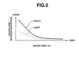
- Fig. 2 is a graph showing a relationship of a water temperature increase rate of fuel and an engine cooling water temperature in accordance with a fuel property.
- Fig. 3 is a flowchart showing a fuel property determination routine of the first embodiment.
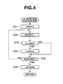
- Fig. 4 is a flowchart showing a subroutine of detecting an expansion stroke maximum angular speed.
- Fig. 5A is a graph showing a change of an angular speed relative to the number of expansion strokes after the cylinder determination
- Fig. 5B is a graph showing a change of an angular acceleration relative to the number of expansion strokes after the cylinder determination.
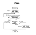
- Fig. 6 is a flowchart showing a routine of setting a fuel property (light or heavy property) for the fuel injection quantity control.
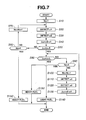
- Fig. 7 is a flowchart showing the fuel property determination routine of a second embodiment according to the present invention.
- Fig. 8 is a flowchart showing the fuel property determination routine of a third embodiment according to the present invention.
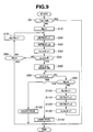
- Fig. 9 is a flowchart showing the fuel property determination routine of a fourth embodiment according to the present invention.
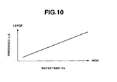
- Fig. 10 is a graph showing a relationship between a threshold ⁇ L and an engine cooling water temperature Tw.
- Fig. 11 is a flowchart showing the fuel property determination routine of a fifth embodiment according to the present invention.
- Figs. 12A and 12B are graphs showing relationships between a deviation range of an angular acceleration and a threshold according to the timing of an engine stroke.
- Fig. 13 is a flowchart showing the fuel property determination routine of a sixth embodiment according to the present invention.
- FIGs. 1 through 6 there is discussed a first embodiment of the fuel property determination system according to the present invention.
- An internal combustion engine 1 of the engine system comprises a plurality of combustion chambers 3 each of which is defined by each cylinder and each piston 2.
- a spark plug 4, an intake valve 5 and an exhaust valve 6 are provided at upper portions of combustion chamber 3 so as to surround combustion chamber 3.
- An intake passage 7 and an exhaust passage 8 are also connected with combustion chamber 3.
- a throttle valve 9 is provided upstream of an intake manifold of intake passage 7.
- a fuel injector 10 of an electromagnetic type is installed at each branch portion of the intake manifold by each cylinder so as to inject fuel toward intake valve 5.
- An engine control unit (ECU) 11 controls the operation of each fuel injector 10.
- ECU 11 is connected with a cam angle sensor 12, a crank angle sensor 13, an airflow meter 14, and a water temperature sensor 15 to receive signals therefrom.
- Cam angle sensor 12 detects a cam angle indicative signal employed for a cylinder determination.
- Crank angle sensor 13 outputs a crank angle signal synchronized with the engine revolution and is capable of determining an engine speed Ne of engine 1.
- Airflow meter 14 is disposed upstream of throttle valve 9 in intake passage 7 and detects an intake air quantity Qa.
- Water temperature sensor 15 detects a temperature Tw of engine cooling water.
- COEF 1 + KAS +...
- Start increase quantity correction coefficient KAS is calculated from the following expression (2).
- KAS MTKAS ⁇ TMKAS
- MTKAS is a table value (water temperature increase rate) according to engine cooling water temperature Tw, and therefore MTKAS takes a large value when engine cooling water temperature Tw is low and decreases as engine cooling water temperature Tw rises.
- Fig. 2 is a schematic graph showing tables of water temperature increase rate (MTKAS).
- MTKAS water temperature increase rate
- a difference of fuel vaporization rate between heavy and light fuels is large when cooling water temperature Tw is low, and is decreased as cooling water temperature Tw rises. Therefore, increase quantity rate MTKAS is set according to the kind of fuel as shown in Fig. 2.
- TMKAS is a table value (time correction coefficient) determined according to the elapsed time from the engine start and is decreased as the time elapses from the engine start.
- ECU 11 executes a control program for achieving the fuel property determining process of the fuel property determining system.
- engine 1 is a four-cylinder engine.
- ECU 11 determines a first fuel injection cylinder of four-cylinder engine 1. More specifically, for the by-cylinder fuel injection control, ECU 11 determines the cylinder of executing the fuel injection. Bases on this cylinder determination, ECU 11 determines which stoke of intake, compression, expansion and exhaust strokes is being executed at each of the four cylinders.
- ECU 11 determines the first fuel injection cylinder at which the fuel injection is firstly executed and the expansion stroke is firstly executed. Normally, the fuel injection is executed during the exhaust stroke of each corresponding cylinder. However, in order to further rapidly start engine 1, at the first fuel injection cylinder the fuel injection is executed during the intake stroke. Therefore, the fuel injection at the first fuel injection cylinder and the fuel injection at the second fuel injection cylinder are simultaneously executed.
- ECU 11 detects angular speed ⁇ at sampling intervals of 10° crank angle.
- step S35 subsequent to the execution of step S34 or the negative determination at step S33, ECU 11 determines whether or not the crank angle of the first fuel injection cylinder reaches near a bottom dead center (BDC) at which the expansion stroke is terminated.
- BDC bottom dead center
- the subroutine for detecting expansion stroke maximum angular speed ⁇ 2 may be arranged to detect an angular speed near an intermediate position of the expansion stroke as a maximum angular speed neighborhood value, or to detect an angular speed near BDC during the expansion stroke. in addition to the detection of the maximum angular speed during the expansion stroke.
- ECU 11 executes the first combustion determination. More specifically, ECU 11 determines whether or not the first combustion is executed, on the basis of a comparison between angular acceleration ⁇ indicative of a changing degree of a revolution speed of each cylinder and a predetermined threshold ⁇ S such as 100,000 deg/s 2 . When ⁇ S, ECU 11 determines that the first combustion was executed. When ⁇ S, the program proceeds to step S60.
- steps S20 through S40 is executed to determine the first combustion of the next cylinder corresponding to Nc. More specifically, at step S50 ECU 11 executes the first combustion of the next cylinder on the basis of angular acceleration ⁇ obtained from compression TDC angular speed ⁇ 1 and expansion stroke maximum angular speed ⁇ 2.
- step S80 ECU 11 determines whether or not ⁇ L, by comparing angular acceleration ⁇ and a predetermined threshold ⁇ L such as 40,000 deg/s 2 . When the determination at step S80 is negative ( ⁇ L), the program proceeds to step S90.
- ECU 11 detects compression-stroke TDC angular speed ⁇ 1 (deg/s).
- ECU detects expansion stroke maximum angular speed ⁇ 2 during the expansion stroke.
- step S80 determines that the fuel in use is light fuel. Thereafter, the present program terminated.
- Fig. 5A is an example showing changes of angular speeds ⁇ (deg/s) relative to a crank angle from the start of the second time expansion stroke to the end of the sixth time expansion stroke.
- an X-axis represents a crank angle and a Y-axis represents angular speed ⁇ .
- Fig. 5B shows angular acceleration ⁇ of each cylinder, which acceleration is derived from the change of angular speed ⁇ in Fig. 5A.
- an X-axis represents the number of times the expansion stroke was executed, which corresponds to the X-axis of Fig. 5a
- a Y-axis represents angular acceleration ⁇ .
- the first fuel injection cylinder is a cylinder wherein the number of times of the expansion strokes is three.
- ⁇ L is satisfied in simultaneously with the first combustion determination, and therefore ECU 11 determines that the fuel in use is light fuel.
- ⁇ L is not satisfied within the first round, that is, within a period that the number of expansion strokes is three to six, and therefore ECU 11 determines that the fuel in use is heavy fuel.
- Fig. 6 is a flowchart showing a fuel injection quantity control fuel property setting routine for executing a heavy fuel setting or light fuel setting for the fuel injection quantity control, using the fuel property determination according to the present invention. This routine starts in response to the turning on of an engine switch.
- ECU 11 executes a heavy fuel setting as an initial setting. That is, ECU 11 firstly uses a heavy fuel table shown in Fig. 2 where both of heavy and light fuel tables are shown. If the light fuel setting is firstly executed under a condition that heavy fuel is actually used, the engine starting performance degrades. Therefore, the heavy fuel setting is firstly executed.
- step S102 ECU 11 determines whether or not the heavy fuel determination is terminated. Until the affirmative determination is made at step S102, step S102 is repeated. When the affirmative determination is made at step S102, the program proceeds to step S103.
- ECU 11 determines whether the fuel in use is heavy fuel, light fuel or indefinite. When ECU 11 determines that the fuel in use is heavy fuel, this routine is terminated since it is not necessary to change the initial setting as to the fuel property. When ECU 11 determines that the fuel in use is light fuel, the routine proceeds to step S104 wherein ECU 11 changes the fuel property setting so as to use the light fuel table shown in Fig. 2. By this changing of the fuel property to the light fuel setting, the fuel consumption of engine 1 is improved.
- the initial fuel property set at the heavy fuel property is maintained to mainly satisfy the engine starting performance and the engine combustion stability during the engine operation.
- the mass of wall fuel increases as the fuel in use becomes heavier in property. Therefore, a fuel quantity supplied into each cylinder varies according to the fuel property of heavy or light. This variation due to the fuel property (heavy or light) generates the variation (large difference) of the degrees of changes of revolution speeds between heavy fuel and light fuel.
- ECU 11 determines the fuel property (heavy or light) of fuel in use. This enables an accurate determination as to the fuel property (heavy or light) of the fuel in use within an extremely short time from an engine start until the termination of the first round of the fourth fuel injection cylinder.
- the angular speed at a point near the intermediate position during the expansion stroke it becomes possible to further accurately detect the degree of change of the revolution speed since the difference between the absolute value of the expansion stroke start angular speed ⁇ 1 and the absolute value of the angular speed ⁇ 2. Further, by using the angular speed at a position near the BDC during the expansion stroke, it becomes possible to stably detect the work load during the expansion stroke.
- the determination of the fuel property is easily executed. Further the determination of the fuel property is further accurately executed by repeating the comparison of the degree of change of the revolution speed of each cylinder with the threshold.
- the degree ⁇ of change of the revolution speed of either cylinder within the first round becomes higher than or equal to the threshold value ⁇ S, it is determined that the fuel in use is light fuel. This enables the fuel property determination to be easily executed. Further, when the degree ⁇ of change of the revolution speed of either cylinder within the first round does not become higher than or equal to the threshold value ⁇ S, it is determines that the fuel in use is heavy fuel. This enables the fuel property determination to be accurately executed.
- the first combustion determination is executed on the basis of the comparison between the degree of change of the revolution speed ⁇ S. Therefore, the first combustion determination is executed using the parameters as same as those of the fuel property determination.
- FIG. 7 there is discussed a second embodiment of the fuel property determination system according to the present invention.
- the construction of the second embodiment is basically the same as that of the first embodiment.
- the second embodiment employs a flowchart for the fuel property determination routine shown in Fig. 7.
- the flowchart of Fig. 7 is different from that of Fig. 3 in further comprising step S160 subsequent to the affirmative determination at step S60.
- the second embodiment when it is impossible to determine the property (heavy or light property) of fuel from the degree of change of the revolution speed by each cylinder, it is considered that the reason of generating no first combustion in the first round is that the fuel vaporization rate is low. Therefore, in the second embodiment, it is determined that the fuel in use is heavy fuel at step S160 when the affirmative determination is made at step S60. However, even if the affirmative determination is made at step S60 in Fig. 3 of the first embodiment, the fuel property table for heavy fuel is used. Therefore, the actual control based on the flowchart of Fig. 7 in the second embodiment is the same as that executed in the first embodiment.
- the degree of the fuel property may be determined according to the level of the degree of change of the revolution speed.
- FIG. 8 there is discussed a third embodiment of the fuel property determination system according to the present invention.
- the construction of the third embodiment is basically the same as that of the first embodiment.
- the third embodiment employs a flowchart for the fuel property determination routine shown in Fig. 8.
- the flowchart of Fig. 8 is different from that of Fig. 3 in further comprising step S5 before step S10.
- ECU 11 firstly determines whether or not engine 1 is started under an engine heated condition, that is, whether or not the engine start is a hot restart. More specifically, ECU 11 obtains a cooling water temperature Tw at a time just before the engine start from cooling water temperature sensor 15 and determines whether cooling water temperature Tw is higher than or equal to a predetermined temperature Twh such as 70°C. When cooling water temperature Tw is higher than or equal to predetermined temperature Twh, ECU 11 determines that the present engine start is the hot restart. Therefore, ECU 11 determines that it is impossible to determine the fuel property, and the program is terminated without executing the fuel property determination. When the negative determination is made at step S5, the program proceeds to step S10.
- cooling water temperature Tw is used as an engine temperature representative value
- a fuel temperature or oil temperature may be used instead of cooling water temperature Tw.
- the determination as to the hot restart may be executed by measuring an engine stop period before the engine start (corresponding to a period from a previous engine stop to a present engine start) and by determining whether or not the engine stop period is shorter than or equal to a predetermined period.
- the advantages given by the first embodiment are also obtained. Further, in case of the hot restart of engine 1, the fuel property determination is prohibited to prevent erroneous determination (misjudgment) since the difference of the degrees of changes of the revolution speeds due to the fuel property becomes small in case of the hot restart. Further, the determination as to the hot restart is easily executed on the basis of the cooling water temperature or engine stop period before the engine start.
- FIG. 9 there is discussed a fourth embodiment of the fuel property determination system according to the present invention.
- the construction of the fourth embodiment is basically the same as that of the first embodiment.
- the fourth embodiment employs a flowchart for the fuel property determination routine shown in Fig. 9.
- the flowchart of Fig. 9 is different from that of Fig. 3 in further comprising step S5 before step S10 and step S55 subsequent to the affirmative determination at step S50.
- ECU 11 firstly determines whether or not engine 1 is started under an engine heated condition, that is, whether or not the engine start is a hot restart. More specifically, ECU 11 obtains a cooling water temperature Tw at a time just before the engine start from cooling water temperature sensor 15 and determines whether cooling water temperature Tw is higher than or equal to a predetermined temperature Twh. When cooling water temperature Tw is higher than or equal to predetermined temperature Twh, ECU 11 determines that the present engine start is the hot restart. Therefore, ECU 11 determines it is impossible to determines the fuel property, and the program proceeds is terminated without executing the fuel property determination. When the negative determination is made at step S5, the program proceeds to step S10.
- cooling water temperature Tw is used as an engine temperature representative value
- a fuel temperature or oil temperature may be used instead of cooling water temperature Tw.
- the determination as to the hot restart may be executed by measuring an engine stop period before the engine start (corresponding to a period from a previous engine stop to a present engine start) and by determining whether or not the engine stop period is shorter than or equal to a predetermined period.
- ECU 11 sets the threshold ⁇ L according to engine cooling water temperature Tw. More specifically, ECU 11 determines threshold ⁇ L from engine cooling water temperature Tw and with reference to a table shown in Fig. 10 which shows a relationship between threshold ⁇ L and engine cooling water temperature Tw. Threshold ⁇ L has been determined such that threshold ⁇ L linearly increases as cooling water temperature increases. In Fig. 10, an applicable range of engine cooling water temperature Tw ranges from -40°C to 70°C, and an applicable range of threshold ⁇ L ranges from 30,000 deg/s 2 to 100,000 deg/s 2 relative to the applicable range of engine cooling water temperature Tw. After the execution of step S55, the program proceeds to step S80.
- the advantages given by the first embodiment are also obtained. Further, the variation of the in-cylinder flowing fuel quantity due to the fuel property decreases as the engine temperature at the engine start increases and as the in-cylinder flowing fuel quantity increases. Although this variation generates the misjudgment as to the fuel property, it becomes possible to highly maintain the determination accuracy by changing the threshold ⁇ L according to the engine temperature condition such as the cooling water temperature Tw.
- the construction of the fifth embodiment is basically the same as that of the first embodiment.
- the fifth embodiment employs a flowchart for the fuel property determination routine shown in Fig. 11.
- the flowchart of Fig. 11 is different from that of Fig. 3 in further comprising steps S72, S74 and S76 between steps S50 and S80.
- the determination at step S72 is negative, that is, the fuel injection cylinder is a second cylinder or later cylinders, the fuel injection is an exhaust stroke fuel injection.
- step S76 ECU 11 sets a relatively small value ⁇ L2 such as 80,000 deg/s 2 at threshold ⁇ L where ⁇ L1> ⁇ L2.
- ECU 11 determines that the fuel in use is light fuel.
- ECU 11 determines that the fuel in use is heavy fuel.
- the reason for changing threshold ⁇ L in the first fuel injection cylinder (intake stroke fuel injection cylinder) and the fuel injection cylinder thereafter is that since the first fuel injection cylinder is an intake stroke cylinder, the in cylinder flowing fuel quantity increases. However, since a time for vaporizing the fuel is short, the difference of the degree of change of the revolution speed due to the difference of the fuel property becomes small.
- the threshold of determining the fuel property is set at a relatively large value ⁇ L1 which is larger than the variation range of the estimated degree of change of the revolution speed.
- the threshold for determining the fuel property is set at the relatively large value ⁇ L1.
- the fuel property determination system is basically arranged to determine the fuel in use as heavy fuel.
- the threshold of determining the fuel property is set at a relatively small value ⁇ L2 which is smaller that the value ⁇ L1 and which is an intermediate value between the variation range of the estimated degree of change of the revolution speed using heavy fuel and the variation range of the estimated degree ⁇ of change of the revolution speed using light fuel.
- the advantages given by the first embodiment are also obtained. Further, at the cylinder in which the fuel injection is executed during the intake stroke in the first round, such as the first fuel injection cylinder, the difference of the degree of change of the revolution speed due to the fuel property becomes small as compared with a case of the cylinder where the fuel injection is executed during other stroke except for the intake stroke. Therefore, there is a possibility that the erroneous determination as to the fuel property is made. However, by changing the threshold ⁇ L according to whether the cylinder to be checked is a cylinder of executing the fuel injection during the intake stroke or cylinder of executing the fuel injection during other stroke (exhaust stroke) except for the intake stroke, the diagnosis accuracy as to the fuel property is improved.
- the diagnosis accuracy is improved.
- the threshold ⁇ L is set at a value greater than the variation range of the estimated degree ⁇ of change of the revolution speed using heavy fuel. This accurately improves the determination accuracy of the fuel property determination.
- FIG. 12 there is discussed a sixth embodiment of the fuel property determination system according to the present invention.
- the construction of the sixth embodiment is basically the same as that of the first embodiment.
- the sixth embodiment employs a flowchart for the fuel property determination routine shown in Fig. 13.
- the flowchart of Fig. 13 is different from that of Fig. 3 in further comprising step S72 subsequent to the affirmative determination at step S50.
- the determination at step S72 is negative, that is, the fuel injection cylinder is a second cylinder or later cylinders, the fuel injection is an exhaust stroke fuel injection.
- step S80 ECU 11 determines whether or not ⁇ L by comparing angular acceleration ⁇ indicative of the degree of change of the revolution speed at each cylinder, which is calculated at step S40 with predetermined threshold ⁇ L which is larger than ⁇ S and corresponds to the value ⁇ L2 shown in Figs. 12A and 12B.
- ⁇ L angular acceleration
- step S90 the program proceeds to step S140.
- step S110 subsequent to the execution of step S100, ECU 11 detects compression TDC angular speed ⁇ 1 (deg/s).
- step S120 ECU detects expansion stroke maximum angular speed ⁇ 2 during the expansion stroke.
- step S80 When the affirmative determination is made at step S80 ( ⁇ L), the program proceeds to step S140 wherein ECU 11 determines that the fuel in use is light fuel. Thereafter, the present program is terminated.
- step S90 negative determination at step S80
- step S150 ECU 11 determines that the fuel in use is heavy fuel. Thereafter, the present program is terminated.
- the advantages given by the fifth embodiment are also obtained. Further, since the sixth embodiment is arranged to prohibit the fuel property determination when the cylinder to be checked is a cylinder in which the fuel injection is executed during the intake stroke of the first round and to execute the fuel property determination when the cylinder to be checked is a cylinder in which the fuel injection is executed during the other stroke except for the intake stroke in the first round, it becomes possible to prevent the misjudgment due to the decrease of the difference between the degrees of changes of the respective revolution speeds in the respective situations using heavy fuel or light fuel.
- the sixth embodiment according to the present invention is arranged such that the fuel property determination is executed on the basis of the degree of change of the revolution speed at the cylinder in which the fuel injection is executed during the other stroke except for the intake stroke, such as the exhaust stroke, it becomes possible to improve the accuracy of the fuel property determination.
Landscapes
- Engineering & Computer Science (AREA)
- Chemical & Material Sciences (AREA)
- Combustion & Propulsion (AREA)
- Mechanical Engineering (AREA)
- General Engineering & Computer Science (AREA)
- Oil, Petroleum & Natural Gas (AREA)
- Combined Controls Of Internal Combustion Engines (AREA)
Applications Claiming Priority (8)
| Application Number | Priority Date | Filing Date | Title |
|---|---|---|---|
| JP2003326990 | 2003-09-19 | ||
| JP2003326991A JP3873955B2 (ja) | 2003-09-19 | 2003-09-19 | 内燃機関の燃料性状判定装置 |
| JP2003326992 | 2003-09-19 | ||
| JP2003326992A JP3873956B2 (ja) | 2003-09-19 | 2003-09-19 | 内燃機関の燃料性状判定装置 |
| JP2003326990A JP3873954B2 (ja) | 2003-09-19 | 2003-09-19 | 内燃機関の燃料性状判定装置 |
| JP2003326991 | 2003-09-19 | ||
| JP2003329357 | 2003-09-22 | ||
| JP2003329357A JP3873959B2 (ja) | 2003-09-22 | 2003-09-22 | 内燃機関の燃料性状判定装置 |
Publications (2)
| Publication Number | Publication Date |
|---|---|
| EP1517024A1 true EP1517024A1 (de) | 2005-03-23 |
| EP1517024B1 EP1517024B1 (de) | 2007-11-28 |
Family
ID=34199157
Family Applications (1)
| Application Number | Title | Priority Date | Filing Date |
|---|---|---|---|
| EP04021387A Expired - Lifetime EP1517024B1 (de) | 2003-09-19 | 2004-09-08 | Kraftstoffeigenschaften Bestimmungsvorrichtung |
Country Status (3)
| Country | Link |
|---|---|
| US (1) | US7050901B2 (de) |
| EP (1) | EP1517024B1 (de) |
| DE (1) | DE602004010340T2 (de) |
Cited By (5)
| Publication number | Priority date | Publication date | Assignee | Title |
|---|---|---|---|---|
| WO2007144745A1 (en) * | 2006-06-13 | 2007-12-21 | Toyota Jidosha Kabushiki Kaisha | Fuel property determination system, and fuel property determination method for internal combustion engine |
| FR2918712A1 (fr) * | 2007-07-09 | 2009-01-16 | Peugeot Citroen Automobiles Sa | Procede de demarrage d'un moteur a combustion interne. |
| RU2507408C2 (ru) * | 2008-09-30 | 2014-02-20 | Пежо Ситроен Отомобиль Са | Способ запуска двигателя внутреннего сгорания |
| WO2014033415A1 (fr) * | 2012-09-03 | 2014-03-06 | Renault S.A.S | Commande d'un moteur thermique utilisant un indice de qualité du carburant alimentant le moteur thermique |
| WO2014033414A1 (fr) * | 2012-09-03 | 2014-03-06 | Renault S.A.S | Commande d'un moteur thermique utilisant un indice de qualité de démarrage du moteur thermique |
Families Citing this family (9)
| Publication number | Priority date | Publication date | Assignee | Title |
|---|---|---|---|---|
| JP4349344B2 (ja) * | 2005-08-23 | 2009-10-21 | トヨタ自動車株式会社 | エンジンの制御装置 |
| JP4667346B2 (ja) * | 2006-08-25 | 2011-04-13 | 本田技研工業株式会社 | 内燃機関の制御装置 |
| JP4667347B2 (ja) * | 2006-09-11 | 2011-04-13 | 本田技研工業株式会社 | 内燃機関の制御装置 |
| DE102008031528B4 (de) | 2008-07-03 | 2016-03-10 | Audi Ag | Verfahren zum Betrieb einer Brennkraftmaschine |
| US7996146B2 (en) * | 2008-12-29 | 2011-08-09 | Caterpillar Inc. | Internal combustion engine, control system and operating method for determining a fuel attribute |
| US8849545B2 (en) * | 2011-03-07 | 2014-09-30 | GM Global Technology Operations LLC | Controlling fuel injection based on fuel volatility |
| JP6292957B2 (ja) * | 2014-04-16 | 2018-03-14 | 日立建機株式会社 | 作業機械の監視システム |
| US9528922B2 (en) * | 2014-06-23 | 2016-12-27 | Caterpillar Inc. | System and method for determining the specific gravity of a gaseous fuel |
| JP6020526B2 (ja) * | 2014-07-31 | 2016-11-02 | トヨタ自動車株式会社 | 内燃機関の燃料性状判定装置 |
Citations (4)
| Publication number | Priority date | Publication date | Assignee | Title |
|---|---|---|---|---|
| US4920494A (en) * | 1986-09-09 | 1990-04-24 | Nissan Motor Company, Limited | Fuel monitoring arrangement for automotive internal combustion engine control system |
| JPH02308945A (ja) * | 1989-05-23 | 1990-12-21 | Mazda Motor Corp | エンジンの燃料成分検出装置 |
| US5711272A (en) * | 1995-12-06 | 1998-01-27 | Denso Corporation | Fuel property detection for an engine using engine speed |
| US6318152B1 (en) * | 1999-05-24 | 2001-11-20 | Mitsubishi Denki Kabushiki Kaisha | Fuel property judgement device for internal combustion engine |
Family Cites Families (4)
| Publication number | Priority date | Publication date | Assignee | Title |
|---|---|---|---|---|
| JPH03233151A (ja) | 1990-02-08 | 1991-10-17 | Suzuki Motor Corp | 内燃機関の燃料供給制御装置 |
| JP3494516B2 (ja) | 1995-11-28 | 2004-02-09 | 株式会社日立ユニシアオートモティブ | 内燃機関の燃料性状検出装置 |
| JP3355269B2 (ja) * | 1996-01-25 | 2002-12-09 | 株式会社日立ユニシアオートモティブ | 内燃機関の燃料性状検出装置 |
| US6079396A (en) * | 1998-04-29 | 2000-06-27 | General Motors Corporation | Automotive cold start fuel volatility compensation |
-
2004
- 2004-09-08 DE DE602004010340T patent/DE602004010340T2/de not_active Expired - Lifetime
- 2004-09-08 EP EP04021387A patent/EP1517024B1/de not_active Expired - Lifetime
- 2004-09-17 US US10/942,906 patent/US7050901B2/en not_active Expired - Lifetime
Patent Citations (4)
| Publication number | Priority date | Publication date | Assignee | Title |
|---|---|---|---|---|
| US4920494A (en) * | 1986-09-09 | 1990-04-24 | Nissan Motor Company, Limited | Fuel monitoring arrangement for automotive internal combustion engine control system |
| JPH02308945A (ja) * | 1989-05-23 | 1990-12-21 | Mazda Motor Corp | エンジンの燃料成分検出装置 |
| US5711272A (en) * | 1995-12-06 | 1998-01-27 | Denso Corporation | Fuel property detection for an engine using engine speed |
| US6318152B1 (en) * | 1999-05-24 | 2001-11-20 | Mitsubishi Denki Kabushiki Kaisha | Fuel property judgement device for internal combustion engine |
Non-Patent Citations (2)
| Title |
|---|
| PATENT ABSTRACTS OF JAPAN vol. 0150, no. 93 (M - 1089) 6 March 1991 (1991-03-06) * |
| PATENT ABSTRACTS OF JAPAN vol. 0160, no. 10 (M - 1199) 13 January 1992 (1992-01-13) * |
Cited By (12)
| Publication number | Priority date | Publication date | Assignee | Title |
|---|---|---|---|---|
| WO2007144745A1 (en) * | 2006-06-13 | 2007-12-21 | Toyota Jidosha Kabushiki Kaisha | Fuel property determination system, and fuel property determination method for internal combustion engine |
| US7778763B2 (en) | 2006-06-13 | 2010-08-17 | Toyota Jidosha Kabushiki Kaisha | Fuel property determination system, and fuel property determination method for internal combustion engine |
| CN101466932B (zh) * | 2006-06-13 | 2012-07-18 | 丰田自动车株式会社 | 内燃发动机的燃料特性确定系统及燃料特性确定方法 |
| FR2918712A1 (fr) * | 2007-07-09 | 2009-01-16 | Peugeot Citroen Automobiles Sa | Procede de demarrage d'un moteur a combustion interne. |
| WO2009007605A3 (fr) * | 2007-07-09 | 2009-03-26 | Peugeot Citroen Automobiles Sa | Procede de demarrage d'un moteur a combustion interne |
| CN101790627B (zh) * | 2007-07-09 | 2013-04-10 | 标致·雪铁龙汽车公司 | 用于启动内燃发动机的方法 |
| US8600649B2 (en) | 2007-07-09 | 2013-12-03 | Peugeot Citroen Automobiles Sa | Method for starting an internal combustion engine |
| RU2507408C2 (ru) * | 2008-09-30 | 2014-02-20 | Пежо Ситроен Отомобиль Са | Способ запуска двигателя внутреннего сгорания |
| WO2014033415A1 (fr) * | 2012-09-03 | 2014-03-06 | Renault S.A.S | Commande d'un moteur thermique utilisant un indice de qualité du carburant alimentant le moteur thermique |
| WO2014033414A1 (fr) * | 2012-09-03 | 2014-03-06 | Renault S.A.S | Commande d'un moteur thermique utilisant un indice de qualité de démarrage du moteur thermique |
| FR2995025A1 (fr) * | 2012-09-03 | 2014-03-07 | Renault Sa | Commande d'un moteur thermique utilisant un indice de qualite du carburant alimentant le moteur thermique |
| FR2995024A1 (fr) * | 2012-09-03 | 2014-03-07 | Renault Sa | Commande d'un moteur thermique utilisant un indice de qualite de demarrage du moteur thermique |
Also Published As
| Publication number | Publication date |
|---|---|
| DE602004010340D1 (de) | 2008-01-10 |
| EP1517024B1 (de) | 2007-11-28 |
| US7050901B2 (en) | 2006-05-23 |
| US20050065710A1 (en) | 2005-03-24 |
| DE602004010340T2 (de) | 2008-03-13 |
Similar Documents
| Publication | Publication Date | Title |
|---|---|---|
| US7909018B2 (en) | Control for determining a firing timing of an internal-combustion engine | |
| CN100404828C (zh) | 在内燃机中控制燃油喷射的装置和方法 | |
| EP1517024B1 (de) | Kraftstoffeigenschaften Bestimmungsvorrichtung | |
| JP3578597B2 (ja) | 直噴火花点火式内燃機関の制御装置 | |
| CN101765710A (zh) | 十六烷值检测装置以及十六烷值检测方法 | |
| KR19990013583A (ko) | 내연 기관용 제어 시스템 | |
| JP2005291182A (ja) | 失火検出装置 | |
| JP3991809B2 (ja) | 内燃機関の始動時燃料噴射装置 | |
| JP2017025777A (ja) | 内燃機関の制御装置 | |
| JPWO2003038263A1 (ja) | エンジン制御装置 | |
| CN101466932B (zh) | 内燃发动机的燃料特性确定系统及燃料特性确定方法 | |
| US11885274B2 (en) | Controller for internal combustion engine, control method for internal combustion engine, and memory medium | |
| JP4281829B2 (ja) | 内燃機関の燃料噴射制御装置 | |
| JP2010156248A (ja) | 内燃機関の制御装置 | |
| JP3873959B2 (ja) | 内燃機関の燃料性状判定装置 | |
| JP2000257467A (ja) | 内燃機関の燃焼制御装置 | |
| US6763806B2 (en) | Combustion control apparatus and combustion control method of internal combustion engine | |
| JP2008309006A (ja) | 内燃機関の制御装置 | |
| JP2007127007A (ja) | 内燃機関の制御装置 | |
| JP2009221899A (ja) | 内燃機関の燃料性状判定装置 | |
| JP4107188B2 (ja) | 筒内直接噴射式火花点火エンジンの制御装置 | |
| CN101578606A (zh) | 用于识别内燃机中相位的方法和系统 | |
| JP3873956B2 (ja) | 内燃機関の燃料性状判定装置 | |
| JP5130186B2 (ja) | 内燃機関の制御装置 | |
| JP2005180356A (ja) | クランク角センサの補正装置および補正方法 |
Legal Events
| Date | Code | Title | Description |
|---|---|---|---|
| PUAI | Public reference made under article 153(3) epc to a published international application that has entered the european phase |
Free format text: ORIGINAL CODE: 0009012 |
|
| 17P | Request for examination filed |
Effective date: 20040908 |
|
| AK | Designated contracting states |
Kind code of ref document: A1 Designated state(s): AT BE BG CH CY CZ DE DK EE ES FI FR GB GR HU IE IT LI LU MC NL PL PT RO SE SI SK TR |
|
| AX | Request for extension of the european patent |
Extension state: AL HR LT LV MK |
|
| AKX | Designation fees paid |
Designated state(s): DE FR GB |
|
| 17Q | First examination report despatched |
Effective date: 20051025 |
|
| GRAP | Despatch of communication of intention to grant a patent |
Free format text: ORIGINAL CODE: EPIDOSNIGR1 |
|
| GRAS | Grant fee paid |
Free format text: ORIGINAL CODE: EPIDOSNIGR3 |
|
| GRAA | (expected) grant |
Free format text: ORIGINAL CODE: 0009210 |
|
| AK | Designated contracting states |
Kind code of ref document: B1 Designated state(s): DE FR GB |
|
| REG | Reference to a national code |
Ref country code: GB Ref legal event code: FG4D |
|
| REF | Corresponds to: |
Ref document number: 602004010340 Country of ref document: DE Date of ref document: 20080110 Kind code of ref document: P |
|
| ET | Fr: translation filed | ||
| PLBE | No opposition filed within time limit |
Free format text: ORIGINAL CODE: 0009261 |
|
| STAA | Information on the status of an ep patent application or granted ep patent |
Free format text: STATUS: NO OPPOSITION FILED WITHIN TIME LIMIT |
|
| 26N | No opposition filed |
Effective date: 20080829 |
|
| PGFP | Annual fee paid to national office [announced via postgrant information from national office to epo] |
Ref country code: DE Payment date: 20130904 Year of fee payment: 10 |
|
| PGFP | Annual fee paid to national office [announced via postgrant information from national office to epo] |
Ref country code: FR Payment date: 20130910 Year of fee payment: 10 Ref country code: GB Payment date: 20130904 Year of fee payment: 10 |
|
| REG | Reference to a national code |
Ref country code: DE Ref legal event code: R119 Ref document number: 602004010340 Country of ref document: DE |
|
| GBPC | Gb: european patent ceased through non-payment of renewal fee |
Effective date: 20140908 |
|
| REG | Reference to a national code |
Ref country code: DE Ref legal event code: R119 Ref document number: 602004010340 Country of ref document: DE Effective date: 20150401 |
|
| REG | Reference to a national code |
Ref country code: FR Ref legal event code: ST Effective date: 20150529 |
|
| PG25 | Lapsed in a contracting state [announced via postgrant information from national office to epo] |
Ref country code: DE Free format text: LAPSE BECAUSE OF NON-PAYMENT OF DUE FEES Effective date: 20150401 Ref country code: GB Free format text: LAPSE BECAUSE OF NON-PAYMENT OF DUE FEES Effective date: 20140908 |
|
| PG25 | Lapsed in a contracting state [announced via postgrant information from national office to epo] |
Ref country code: FR Free format text: LAPSE BECAUSE OF NON-PAYMENT OF DUE FEES Effective date: 20140930 |