EP1516941B1 - Dispositif de type rotatif destine a la production en grandes quantites de pellicules de depot chimique en phase vapeur et procede de production de pellicules de depot chimique en phase vapeur sur une surface dans un contenant plastique - Google Patents
Dispositif de type rotatif destine a la production en grandes quantites de pellicules de depot chimique en phase vapeur et procede de production de pellicules de depot chimique en phase vapeur sur une surface dans un contenant plastique Download PDFInfo
- Publication number
- EP1516941B1 EP1516941B1 EP03760909A EP03760909A EP1516941B1 EP 1516941 B1 EP1516941 B1 EP 1516941B1 EP 03760909 A EP03760909 A EP 03760909A EP 03760909 A EP03760909 A EP 03760909A EP 1516941 B1 EP1516941 B1 EP 1516941B1
- Authority
- EP
- European Patent Office
- Prior art keywords
- film forming
- housing spaces
- external electrode
- circle
- housing
- Prior art date
- Legal status (The legal status is an assumption and is not a legal conclusion. Google has not performed a legal analysis and makes no representation as to the accuracy of the status listed.)
- Expired - Lifetime
Links
- 229920003023 plastic Polymers 0.000 title claims abstract description 108
- 239000004033 plastic Substances 0.000 title claims abstract description 108
- 238000004519 manufacturing process Methods 0.000 claims abstract description 55
- 239000000126 substance Substances 0.000 claims abstract description 4
- 238000000034 method Methods 0.000 claims description 39
- 230000008569 process Effects 0.000 claims description 26
- 229930195733 hydrocarbon Natural products 0.000 claims description 23
- 150000002430 hydrocarbons Chemical class 0.000 claims description 22
- 239000004215 Carbon black (E152) Substances 0.000 claims description 19
- 239000010408 film Substances 0.000 description 223
- 239000007789 gas Substances 0.000 description 68
- 238000005229 chemical vapour deposition Methods 0.000 description 53
- 230000015572 biosynthetic process Effects 0.000 description 23
- 229920005989 resin Polymers 0.000 description 19
- 239000011347 resin Substances 0.000 description 19
- 238000009826 distribution Methods 0.000 description 16
- 230000007246 mechanism Effects 0.000 description 10
- -1 polyethylene terephthalate Polymers 0.000 description 9
- 229920000139 polyethylene terephthalate Polymers 0.000 description 7
- 239000005020 polyethylene terephthalate Substances 0.000 description 7
- 235000013361 beverage Nutrition 0.000 description 6
- 239000006185 dispersion Substances 0.000 description 5
- HSFWRNGVRCDJHI-UHFFFAOYSA-N alpha-acetylene Natural products C#C HSFWRNGVRCDJHI-UHFFFAOYSA-N 0.000 description 4
- 229910052799 carbon Inorganic materials 0.000 description 4
- 125000002534 ethynyl group Chemical group [H]C#C* 0.000 description 4
- UHOVQNZJYSORNB-UHFFFAOYSA-N Benzene Chemical compound C1=CC=CC=C1 UHOVQNZJYSORNB-UHFFFAOYSA-N 0.000 description 3
- OKTJSMMVPCPJKN-UHFFFAOYSA-N Carbon Chemical compound [C] OKTJSMMVPCPJKN-UHFFFAOYSA-N 0.000 description 3
- LYCAIKOWRPUZTN-UHFFFAOYSA-N Ethylene glycol Chemical compound OCCO LYCAIKOWRPUZTN-UHFFFAOYSA-N 0.000 description 3
- YXFVVABEGXRONW-UHFFFAOYSA-N Toluene Chemical compound CC1=CC=CC=C1 YXFVVABEGXRONW-UHFFFAOYSA-N 0.000 description 3
- 235000014171 carbonated beverage Nutrition 0.000 description 3
- 239000000463 material Substances 0.000 description 3
- 239000010409 thin film Substances 0.000 description 3
- XKRFYHLGVUSROY-UHFFFAOYSA-N Argon Chemical compound [Ar] XKRFYHLGVUSROY-UHFFFAOYSA-N 0.000 description 2
- 229920000089 Cyclic olefin copolymer Polymers 0.000 description 2
- XDTMQSROBMDMFD-UHFFFAOYSA-N Cyclohexane Chemical compound C1CCCCC1 XDTMQSROBMDMFD-UHFFFAOYSA-N 0.000 description 2
- CTQNGGLPUBDAKN-UHFFFAOYSA-N O-Xylene Chemical group CC1=CC=CC=C1C CTQNGGLPUBDAKN-UHFFFAOYSA-N 0.000 description 2
- URLKBWYHVLBVBO-UHFFFAOYSA-N Para-Xylene Chemical group CC1=CC=C(C)C=C1 URLKBWYHVLBVBO-UHFFFAOYSA-N 0.000 description 2
- 239000004696 Poly ether ether ketone Substances 0.000 description 2
- 239000004743 Polypropylene Substances 0.000 description 2
- 150000001338 aliphatic hydrocarbons Chemical class 0.000 description 2
- KDKYADYSIPSCCQ-UHFFFAOYSA-N but-1-yne Chemical compound CCC#C KDKYADYSIPSCCQ-UHFFFAOYSA-N 0.000 description 2
- 230000008859 change Effects 0.000 description 2
- 239000004020 conductor Substances 0.000 description 2
- 229920001577 copolymer Polymers 0.000 description 2
- 235000015203 fruit juice Nutrition 0.000 description 2
- IVSZLXZYQVIEFR-UHFFFAOYSA-N m-xylene Chemical group CC1=CC=CC(C)=C1 IVSZLXZYQVIEFR-UHFFFAOYSA-N 0.000 description 2
- 229920002530 polyetherether ketone Polymers 0.000 description 2
- 229920001155 polypropylene Polymers 0.000 description 2
- 238000004904 shortening Methods 0.000 description 2
- WSSSPWUEQFSQQG-UHFFFAOYSA-N 4-methyl-1-pentene Chemical compound CC(C)CC=C WSSSPWUEQFSQQG-UHFFFAOYSA-N 0.000 description 1
- NLHHRLWOUZZQLW-UHFFFAOYSA-N Acrylonitrile Chemical compound C=CC#N NLHHRLWOUZZQLW-UHFFFAOYSA-N 0.000 description 1
- LFQSCWFLJHTTHZ-UHFFFAOYSA-N Ethanol Chemical compound CCO LFQSCWFLJHTTHZ-UHFFFAOYSA-N 0.000 description 1
- VGGSQFUCUMXWEO-UHFFFAOYSA-N Ethene Chemical compound C=C VGGSQFUCUMXWEO-UHFFFAOYSA-N 0.000 description 1
- 239000005977 Ethylene Substances 0.000 description 1
- 229920000219 Ethylene vinyl alcohol Polymers 0.000 description 1
- PYVHTIWHNXTVPF-UHFFFAOYSA-N F.F.F.F.C=C Chemical compound F.F.F.F.C=C PYVHTIWHNXTVPF-UHFFFAOYSA-N 0.000 description 1
- 229930182556 Polyacetal Natural products 0.000 description 1
- 239000004962 Polyamide-imide Substances 0.000 description 1
- 229920001328 Polyvinylidene chloride Polymers 0.000 description 1
- XUIMIQQOPSSXEZ-UHFFFAOYSA-N Silicon Chemical compound [Si] XUIMIQQOPSSXEZ-UHFFFAOYSA-N 0.000 description 1
- 238000010521 absorption reaction Methods 0.000 description 1
- 229920000122 acrylonitrile butadiene styrene Polymers 0.000 description 1
- 239000004676 acrylonitrile butadiene styrene Substances 0.000 description 1
- XECAHXYUAAWDEL-UHFFFAOYSA-N acrylonitrile butadiene styrene Chemical compound C=CC=C.C=CC#N.C=CC1=CC=CC=C1 XECAHXYUAAWDEL-UHFFFAOYSA-N 0.000 description 1
- 229920001893 acrylonitrile styrene Polymers 0.000 description 1
- 239000003905 agrochemical Substances 0.000 description 1
- 229910003481 amorphous carbon Inorganic materials 0.000 description 1
- 229910052786 argon Inorganic materials 0.000 description 1
- 150000004945 aromatic hydrocarbons Chemical class 0.000 description 1
- QVGXLLKOCUKJST-UHFFFAOYSA-N atomic oxygen Chemical compound [O] QVGXLLKOCUKJST-UHFFFAOYSA-N 0.000 description 1
- 230000004888 barrier function Effects 0.000 description 1
- 230000005540 biological transmission Effects 0.000 description 1
- 239000003990 capacitor Substances 0.000 description 1
- 239000011248 coating agent Substances 0.000 description 1
- 238000000576 coating method Methods 0.000 description 1
- 229910003460 diamond Inorganic materials 0.000 description 1
- 239000010432 diamond Substances 0.000 description 1
- 239000003814 drug Substances 0.000 description 1
- 230000000694 effects Effects 0.000 description 1
- 235000013305 food Nutrition 0.000 description 1
- 229910021385 hard carbon Inorganic materials 0.000 description 1
- 239000001307 helium Substances 0.000 description 1
- 229910052734 helium Inorganic materials 0.000 description 1
- SWQJXJOGLNCZEY-UHFFFAOYSA-N helium atom Chemical compound [He] SWQJXJOGLNCZEY-UHFFFAOYSA-N 0.000 description 1
- 230000006872 improvement Effects 0.000 description 1
- 229920000554 ionomer Polymers 0.000 description 1
- WABPQHHGFIMREM-UHFFFAOYSA-N lead(0) Chemical compound [Pb] WABPQHHGFIMREM-UHFFFAOYSA-N 0.000 description 1
- 239000007788 liquid Substances 0.000 description 1
- 238000012423 maintenance Methods 0.000 description 1
- 239000002184 metal Substances 0.000 description 1
- VNWKTOKETHGBQD-UHFFFAOYSA-N methane Chemical compound C VNWKTOKETHGBQD-UHFFFAOYSA-N 0.000 description 1
- OKKJLVBELUTLKV-UHFFFAOYSA-N methanol Substances OC OKKJLVBELUTLKV-UHFFFAOYSA-N 0.000 description 1
- 239000000203 mixture Substances 0.000 description 1
- 229910052756 noble gas Inorganic materials 0.000 description 1
- 229940078552 o-xylene Drugs 0.000 description 1
- 239000001301 oxygen Substances 0.000 description 1
- 229910052760 oxygen Inorganic materials 0.000 description 1
- 238000005268 plasma chemical vapour deposition Methods 0.000 description 1
- 229920003207 poly(ethylene-2,6-naphthalate) Polymers 0.000 description 1
- 229920003229 poly(methyl methacrylate) Polymers 0.000 description 1
- 229920002492 poly(sulfone) Polymers 0.000 description 1
- 229920006122 polyamide resin Polymers 0.000 description 1
- 229920002312 polyamide-imide Polymers 0.000 description 1
- 229920001707 polybutylene terephthalate Polymers 0.000 description 1
- 229920005668 polycarbonate resin Polymers 0.000 description 1
- 239000004431 polycarbonate resin Substances 0.000 description 1
- 229920000728 polyester Polymers 0.000 description 1
- 229920001225 polyester resin Polymers 0.000 description 1
- 239000004645 polyester resin Substances 0.000 description 1
- 239000011112 polyethylene naphthalate Substances 0.000 description 1
- 229920013716 polyethylene resin Polymers 0.000 description 1
- 229920005644 polyethylene terephthalate glycol copolymer Polymers 0.000 description 1
- 229920001721 polyimide Polymers 0.000 description 1
- 239000004926 polymethyl methacrylate Substances 0.000 description 1
- 229920006324 polyoxymethylene Polymers 0.000 description 1
- 229920005990 polystyrene resin Polymers 0.000 description 1
- 239000004800 polyvinyl chloride Substances 0.000 description 1
- 229920000915 polyvinyl chloride Polymers 0.000 description 1
- 239000005033 polyvinylidene chloride Substances 0.000 description 1
- 235000013324 preserved food Nutrition 0.000 description 1
- SCUZVMOVTVSBLE-UHFFFAOYSA-N prop-2-enenitrile;styrene Chemical compound C=CC#N.C=CC1=CC=CC=C1 SCUZVMOVTVSBLE-UHFFFAOYSA-N 0.000 description 1
- MWWATHDPGQKSAR-UHFFFAOYSA-N propyne Chemical group CC#C MWWATHDPGQKSAR-UHFFFAOYSA-N 0.000 description 1
- 229910052710 silicon Inorganic materials 0.000 description 1
- 239000010703 silicon Substances 0.000 description 1
- 235000014214 soft drink Nutrition 0.000 description 1
- 125000000383 tetramethylene group Chemical group [H]C([H])([*:1])C([H])([H])C([H])([H])C([H])([H])[*:2] 0.000 description 1
- 238000007740 vapor deposition Methods 0.000 description 1
Images


Classifications
-
- C—CHEMISTRY; METALLURGY
- C23—COATING METALLIC MATERIAL; COATING MATERIAL WITH METALLIC MATERIAL; CHEMICAL SURFACE TREATMENT; DIFFUSION TREATMENT OF METALLIC MATERIAL; COATING BY VACUUM EVAPORATION, BY SPUTTERING, BY ION IMPLANTATION OR BY CHEMICAL VAPOUR DEPOSITION, IN GENERAL; INHIBITING CORROSION OF METALLIC MATERIAL OR INCRUSTATION IN GENERAL
- C23C—COATING METALLIC MATERIAL; COATING MATERIAL WITH METALLIC MATERIAL; SURFACE TREATMENT OF METALLIC MATERIAL BY DIFFUSION INTO THE SURFACE, BY CHEMICAL CONVERSION OR SUBSTITUTION; COATING BY VACUUM EVAPORATION, BY SPUTTERING, BY ION IMPLANTATION OR BY CHEMICAL VAPOUR DEPOSITION, IN GENERAL
- C23C16/00—Chemical coating by decomposition of gaseous compounds, without leaving reaction products of surface material in the coating, i.e. chemical vapour deposition [CVD] processes
- C23C16/04—Coating on selected surface areas, e.g. using masks
- C23C16/045—Coating cavities or hollow spaces, e.g. interior of tubes; Infiltration of porous substrates
-
- B—PERFORMING OPERATIONS; TRANSPORTING
- B65—CONVEYING; PACKING; STORING; HANDLING THIN OR FILAMENTARY MATERIAL
- B65D—CONTAINERS FOR STORAGE OR TRANSPORT OF ARTICLES OR MATERIALS, e.g. BAGS, BARRELS, BOTTLES, BOXES, CANS, CARTONS, CRATES, DRUMS, JARS, TANKS, HOPPERS, FORWARDING CONTAINERS; ACCESSORIES, CLOSURES, OR FITTINGS THEREFOR; PACKAGING ELEMENTS; PACKAGES
- B65D23/00—Details of bottles or jars not otherwise provided for
- B65D23/02—Linings or internal coatings
-
- C—CHEMISTRY; METALLURGY
- C23—COATING METALLIC MATERIAL; COATING MATERIAL WITH METALLIC MATERIAL; CHEMICAL SURFACE TREATMENT; DIFFUSION TREATMENT OF METALLIC MATERIAL; COATING BY VACUUM EVAPORATION, BY SPUTTERING, BY ION IMPLANTATION OR BY CHEMICAL VAPOUR DEPOSITION, IN GENERAL; INHIBITING CORROSION OF METALLIC MATERIAL OR INCRUSTATION IN GENERAL
- C23C—COATING METALLIC MATERIAL; COATING MATERIAL WITH METALLIC MATERIAL; SURFACE TREATMENT OF METALLIC MATERIAL BY DIFFUSION INTO THE SURFACE, BY CHEMICAL CONVERSION OR SUBSTITUTION; COATING BY VACUUM EVAPORATION, BY SPUTTERING, BY ION IMPLANTATION OR BY CHEMICAL VAPOUR DEPOSITION, IN GENERAL
- C23C16/00—Chemical coating by decomposition of gaseous compounds, without leaving reaction products of surface material in the coating, i.e. chemical vapour deposition [CVD] processes
- C23C16/22—Chemical coating by decomposition of gaseous compounds, without leaving reaction products of surface material in the coating, i.e. chemical vapour deposition [CVD] processes characterised by the deposition of inorganic material, other than metallic material
- C23C16/26—Deposition of carbon only
-
- C—CHEMISTRY; METALLURGY
- C23—COATING METALLIC MATERIAL; COATING MATERIAL WITH METALLIC MATERIAL; CHEMICAL SURFACE TREATMENT; DIFFUSION TREATMENT OF METALLIC MATERIAL; COATING BY VACUUM EVAPORATION, BY SPUTTERING, BY ION IMPLANTATION OR BY CHEMICAL VAPOUR DEPOSITION, IN GENERAL; INHIBITING CORROSION OF METALLIC MATERIAL OR INCRUSTATION IN GENERAL
- C23C—COATING METALLIC MATERIAL; COATING MATERIAL WITH METALLIC MATERIAL; SURFACE TREATMENT OF METALLIC MATERIAL BY DIFFUSION INTO THE SURFACE, BY CHEMICAL CONVERSION OR SUBSTITUTION; COATING BY VACUUM EVAPORATION, BY SPUTTERING, BY ION IMPLANTATION OR BY CHEMICAL VAPOUR DEPOSITION, IN GENERAL
- C23C16/00—Chemical coating by decomposition of gaseous compounds, without leaving reaction products of surface material in the coating, i.e. chemical vapour deposition [CVD] processes
- C23C16/44—Chemical coating by decomposition of gaseous compounds, without leaving reaction products of surface material in the coating, i.e. chemical vapour deposition [CVD] processes characterised by the method of coating
- C23C16/50—Chemical coating by decomposition of gaseous compounds, without leaving reaction products of surface material in the coating, i.e. chemical vapour deposition [CVD] processes characterised by the method of coating using electric discharges
- C23C16/505—Chemical coating by decomposition of gaseous compounds, without leaving reaction products of surface material in the coating, i.e. chemical vapour deposition [CVD] processes characterised by the method of coating using electric discharges using radio frequency discharges
-
- C—CHEMISTRY; METALLURGY
- C23—COATING METALLIC MATERIAL; COATING MATERIAL WITH METALLIC MATERIAL; CHEMICAL SURFACE TREATMENT; DIFFUSION TREATMENT OF METALLIC MATERIAL; COATING BY VACUUM EVAPORATION, BY SPUTTERING, BY ION IMPLANTATION OR BY CHEMICAL VAPOUR DEPOSITION, IN GENERAL; INHIBITING CORROSION OF METALLIC MATERIAL OR INCRUSTATION IN GENERAL
- C23C—COATING METALLIC MATERIAL; COATING MATERIAL WITH METALLIC MATERIAL; SURFACE TREATMENT OF METALLIC MATERIAL BY DIFFUSION INTO THE SURFACE, BY CHEMICAL CONVERSION OR SUBSTITUTION; COATING BY VACUUM EVAPORATION, BY SPUTTERING, BY ION IMPLANTATION OR BY CHEMICAL VAPOUR DEPOSITION, IN GENERAL
- C23C16/00—Chemical coating by decomposition of gaseous compounds, without leaving reaction products of surface material in the coating, i.e. chemical vapour deposition [CVD] processes
- C23C16/44—Chemical coating by decomposition of gaseous compounds, without leaving reaction products of surface material in the coating, i.e. chemical vapour deposition [CVD] processes characterised by the method of coating
- C23C16/54—Apparatus specially adapted for continuous coating
Definitions
- the present invention is related to a film forming apparatus which carries out continuous manufacturing by a rotary system, and in particular to a CVD film forming apparatus for mass production in a CVD film forming apparatus which coats the internal surface of a plastic container with a CVD film by a CVD (Chemical Vapor Deposition, chemical vapor growing) method, and a film forming method thereof.
- CVD Chemical Vapor Deposition, chemical vapor growing
- a vapor deposition apparatus which uses a CVD method, in particular, a plasma CVD method to vapor deposit a DLC (Diamond Like Carbon) film on the internal surface of a plastic container in order to improve the gas barrier properties and the like of containers such as containers for carbonated beverages and high fruit juice beverages and the like is disclosed in Japanese Laid-Open Patent Publication No. HEI 8-53117 , for example. Further, Japanese Laid-Open Patent Publication No. HEI 10-258825 discloses a manufacturing apparatus for mass producing DLC film coated plastic containers and a manufacturing method thereof.
- a CVD method in particular, a plasma CVD method to vapor deposit a DLC (Diamond Like Carbon) film on the internal surface of a plastic container in order to improve the gas barrier properties and the like of containers such as containers for carbonated beverages and high fruit juice beverages and the like is disclosed in Japanese Laid-Open Patent Publication No. HEI 8-53117 , for example.
- Japanese Laid-Open Patent Publication No. HEI 10-258825 corresponds to EP 1 010 773 A1 and is considered as the closest prior art.
- the document discloses an apparatus in which a plurality of chambers is arranged at equal intervals on the same circle, the external electrodes of adjacent chambers are connected by lead wires, and each external electrode is connected to a high frequency power source by a lead wire in a straight line extending from the center of the circle.
- This apparatus carries out film formation simultaneously in a plurality of containers.
- a mass production apparatus for forming a CVD film on the internal surfaces of containers In developing a mass production apparatus for forming a CVD film on the internal surfaces of containers, the present inventors reached the conclusion that in order to miniaturize the apparatus and raise the mass production efficiency, instead of forming a film simultaneously in all film forming chambers, preferably a plurality of film forming chambers is arranged in the shape of a circle on a rotation support body, the rotation support body is rotated at a fixed speed, and the manufacturing cycle of each film forming chamber is controlled during the time the rotation support body (turntable) undergoes one rotation.
- the manufacturing cycle is a cycle which includes (1) a container loading process for plastic containers, (2) a pre-film-formation gas adjustment process for the inside of the containers, (3) a CVD film forming process which converts the source gas to plasma, (4) a post-film-formation gas adjustment process for the inside of the containers, and (5) a coated container removal process.
- the CVD film forming apparatus carries out one manufacturing cycle for the film forming chambers arranged on a circle during the time the rotation support body undergoes one rotation is classified as a rotary type, and this is different from a single application apparatus and the batch system apparatus disclosed in Japanese Laid-Open Patent Publication No. HEI 10-258825 .
- the matching time shift of about 0.1 ⁇ 1 second has a large effect on the dispersion of film thicknesses of the DLC films, namely, the film thickness dispersion between the plastic containers. Accordingly, this creates dispersion in the quality of the DLC films.
- the dispersion is even larger than the case of the embodiment described above.
- the present inventors call this novel external electrode structure a "multiple-integrated external electrode".
- the multiple-integrated external electrode makes it possible to reduce the film thickness dispersion, achieve compactness by reducing the number of structural components and simplifying the structure, achieve easy maintenance, and reduce the cost of the apparatus.
- the apparatus by forming the apparatus as a rotary type, it is an object to (1) achieve a small size, (2) make it unnecessary to form an exhaust rate large enough to create a vacuum simultaneously in all the film forming chambers, (3) not apply wasted power by not carrying out control to oppose the rotation inertia of the rotation support body, (4) form a long CVD film formation time for one manufacturing cycle interval, (5) improve the mass production efficiency by shortening the time outside the film forming process, and (6) reduce the required output of the high frequency power source compared to the film forming apparatus that carries out film formation simultaneously for all the film forming chambers.
- a rotary type CVD film forming apparatus a plurality of film forming chambers is arranged on a rotation support body to form a rotary type, but the containers do not always need to be arranged in one row in the circumferential direction of the same circle which uses the rotation axis of the rotation support body as a center point as in a beverage filling apparatus, for example.
- the multiple-integrated external electrode makes it possible to increase the number of rows of housing spaces in the circumferential direction described above. For example, when changing from one row to two rows, it is an object to double the productivity per unit time by ensuring that two film forming chambers undergo film formation at exactly the same timing in accordance with the rotation of the rotation support body with the size of the apparatus becoming only slightly larger. Further, it is an object to triple the productivity in the same way by forming three rows.
- the rotary type CVD film forming apparatus for mass production includes a film forming chamber formed by providing one columnar body serving as an external electrode having a plurality of housing spaces for housing one plastic container each in one said housing space so that the central axis of each of said housing spaces is parallel with the central axis of said external electrode and said housing spaces are arranged side by side on the same circle which uses the central axis of the external electrode as a center point, providing internal electrodes which can be arranged to be freely inserted from the mouth portion into the inside of the plastic containers loaded in each of said housing spaces, providing an insulating member to form an insulating state between the internal electrodes and the external electrode when said internal electrodes are inserted inside said plastic containers, and providing a cover which is closed for reducing the pressure inside said housing spaces, wherein a plurality of said film forming chambers is arranged on a rotation support body at equal intervals in a circular state, source gas introduction means which introduce a source gas that is converted
- said housing spaces are arranged side by side at equal intervals on the same circle which uses the central axis of said external electrode as a center point.
- rotary type CVD film forming apparatus for mass production described in Claim 1 or 2
- two housing spaces are provided in one external electrode, and said film forming chambers are arranged at equal intervals on said rotation support body so that said housing spaces are arranged on the same circle which uses the rotation axis of said rotation support body as a center point.
- preferably two housing spaces are provided in one external electrode, and when said film forming chambers are arranged on said rotation support body, one housing space is arranged outside a circle formed by each of said film forming chambers and the other housing space is arranged inside said circle, whereby the housing spaces of said external electrodes are arranged in two rows in the circumferential direction of said circle.
- preferably three housing spaces are provided in one external electrode, and when said film forming chambers are arranged on said rotation support body, a relationship is formed so that two housing spaces of every other film forming chamber are arranged outside the circle formed by the film forming chambers with the remaining one housing space arranged inside said circle, and two housing spaces of the adjacent film forming chambers are arranged inside said circle with the remaining one housing space arranged outside said circle, whereby the housing spaces of said external electrodes are arranged in two rows in the circumferential direction of said circle.
- housing spaces are provided in one external electrode, and when said film forming chambers are arranged on said rotation support body, two housing spaces are arranged outside a circle formed by the film forming chambers, and the other two housing spaces are arranged inside said circle, whereby the housing spaces of said external electrodes are arranged in two rows in the circumferential direction of said circle.
- said housing spaces are arranged in two rows in the circumferential direction of said circle with said circle interposed between mutually adjacent housing spaces, or said housing spaces are arranged in two rows in said circumferential direction with said circle interposed between mutually shifted housing spaces.
- the method of forming a CVD film on the internal surfaces of plastic containers carries out a container loading process which loads said plastic containers in said film forming chambers by housing said plastic containers in said housing spaces, a pre-film-formation gas adjustment process which replaces the inside of said plastic containers with a source gas adjusted to a prescribed film forming pressure, a CVD film forming process which converts said source gas to plasma and forms a CVD film on the internal surfaces of said plastic containers, a post-film-formation gas adjustment process which opens the inside of coated plastic containers to the atmosphere, and a container removal process which removes said coated containers from said film forming chambers during the time the rotation support body described in Claims 1 ⁇ 7 undergoes one rotation at a fixed speed.
- a hydrocarbon gas or a Si-containing hydrocarbon gas is used as said source gas, and a DLC film is formed as said CVD film.
- the present invention makes it possible to provide a small-sized, inexpensive CVD film forming apparatus having a high mass production efficiency which is an apparatus of the type which carries out one manufacturing cycle on the film forming chambers during the time the rotation support body undergoes one rotation, in particular, a rotary type apparatus for mass production which forms a CVD film on the internal surfaces of plastic containers.
- the productivity is increased while preventing the container loading mechanism and the container removing mechanism from becoming complex in the rotary type apparatus.
- the present invention makes it possible to simultaneously make it unnecessary to form an exhaust rate large enough to create a vacuum simultaneously in all the film forming chambers, makes it unnecessary to apply wasted power because control to oppose the rotation inertia of the rotation support body is not carried out, form a long CVD film formation time for one manufacturing cycle interval, raise the mass production efficiency by shortening the time outside the film forming process, make the number of high frequency power sources and matching boxes smaller than the number of film forming chambers, and reduce the required output of the high frequency power source compared to the film forming apparatus that carries out film formation simultaneously for all the film forming chambers.
- the present invention makes it possible to carry out cooperation smoothly between a container supply line, the present apparatus and a coated container conveying line by completing the entire film forming process during the time the rotation support body undergoes one rotation in the rotary type apparatus of the present invention.
- the present invention makes it possible to provide a rotary type CVD film forming apparatus for mass production and a CVD film forming method which form a CVD film, in particular, a DLC film using a hydrocarbon gas or a Si-containing hydrocarbon gas as a source gas.
- 1 is a lower portion external electrode
- 2 is an upper portion external electrode
- 3 is an external electrode
- 4a is an insulating member
- 4b is a cover
- 6 is a film forming chamber
- 7, 7a, 7b, 7c, 7d are plastic containers
- 8 is an O-ring
- 9, 9a, 9b, 9c, 9d are internal electrodes
- 10, 11, 22 are pipelines
- 14 is an automatic matching device
- 15 is a high frequency power source (RF power source)
- 16, 17, 18 are vacuum valves
- 19 is a mass flow controller
- 20 is a source gas generating source
- 21 is a vacuum pump
- 27 is a leak gas (air) supply source
- 28 is a vacuum gage
- 29 is an exhaust duct
- 30 is a high frequency output supply rod
- 32 is a high frequency output supply rod connection contact
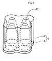
- 40 is a housing space
- 41 is a rotation support boby 49, 49a, 49b are gas blowout holes
- x 1 is the
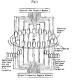
- Fig. 1 is a conceptual drawing which shows the relationship of the basic structure of a rotary type CVD film forming apparatus for mass production according to the present invention.
- the rotary type CVD film forming apparatus for mass production according to the present invention is provided with film forming chambers, a rotation support body on which the plurality of film forming chambers is arranged at equal intervals on a circle, source gas introduction means which introduce a source gas that is converted to plasma to the inside of plastic containers housed in each film forming chamber, and high frequency supply means which supply a high frequency to the external electrode of each film forming chamber, and forms a CVD film on the internal surface of the plastic containers.
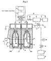
- Fig. 2 is a conceptual drawing showing the structure of one film forming chamber from those of Fig. 1 , and the portion of the film forming chamber 6 of Fig. 2 is a cross-sectional conceptual drawing taken along the axial direction of the container.
- the film forming chamber 6 is formed from an external electrode 3 formed to have the shape of one cylindrical body provided with a plurality of housing spaces 40a, 40c which each house one of plastic containers 7a, 7c, internal electrodes 9a, 9c which can be arranged to be freely inserted from the mouth portion to the inside of the plastic containers 7a, 7c loaded respectively in the housing spaces 40a, 40c, an insulating member 4a which forms an insulating state between the internal electrodes 9a, 9c and the external electrode 3 when the internal electrodes 9a, 9c are inserted inside the plastic containers 7a, 7c, and a cover 4b which closes the film forming chamber 6 so that pressure can be reduced inside the housing spaces 40a, 40c.
- the cover 4b is formed from a conducting material, and supports the internal electrodes 9a, 9c.
- a space which communicates with the housing spaces 40a, 40c is provided inside the cover 4b, and this space together with the housing spaces 40a, 40c form a pressure-reducing space.
- exhaust means constructed from a vacuum pump 21 and the like are connected to the cover 4b, and this forms a structure in which it is possible to reduce the pressure in the housing spaces 40a, 40c by reducing the pressure in the space of the cover 4b.
- the insulating member 4a is arranged below the cover 4b, and the external electrode 3 is arranged below the insulating member 4a.
- an insulating state is formed between the cover 4b, the conducting internal electrodes 9a, 9c and the external electrode 3 by the insulating member 4a.
- the external electrode 3 is formed from an upper portion external electrode 2 and a lower portion external electrode 1, and is constructed so that the upper portion of the lower portion external electrode 1 is removably mounted to the lower portion of the upper portion external electrode 2 via an O-ring 8.
- the plastic containers 7a, 7c can be loaded by removing and mounting the upper portion external electrode 2 and the lower portion external electrode 1.
- the external electrode 3 is divided into the two electrodes of the lower portion external electrode 1 and the upper portion external electrode 2, but in order to make the CVD film have a uniform thickness or the like, the external electrode may be divided into three electrodes such as a bottom portion electrode, a trunk portion electrode and a shoulder portion electrode, for example, or into more than three electrodes, wherein each electrode may be sealed by the interposing of an O-ring, for example, and electrically insulated by a fluororesin sheet or a polyimide film or a polyether ether ketone (PEEK) film.
- PEEK polyether ether ketone
- the spaces 40a, 40c are formed inside the external electrode 3, and these spaces are housing spaces for housing the coating object plastic containers 7a, 7c, for example, PET bottles which are containers made from polyethylene terephthalate resin.
- the housing spaces 40a, 40c inside the external electrode 3 are formed so as to be possible to house a plastic container 7 housed therein.
- the housing spaces 40a, 40c are preferably formed to be slightly larger than external shape of the plastic container.
- the inner wall surfaces of the container housing spaces 40a, 40c are preferably formed to have a shape (similar shape) that surrounds the vicinity of the outside of the plastic containers 7a, 7c. This is done in order to create a uniform self bias voltage on the wall surfaces of the plastic containers.
- the inner wall surfaces of the housing spaces of the external electrode do not need to be formed with a similar shape.
- An opening which communicates with the housing spaces 40a, 40c inside the external electrode 3 is formed in the cover 4b. Further, a space is provided in the inside of the cover 4b, and this space communicates with the housing spaces 40a, 40c inside the external electrode 3 via the opening described above.
- the housing spaces 40a, 40c are sealed from the outside by the O-ring 8 arranged between the upper portion external electrode 2 and the lower portion external electrode 1, and this makes it possible to reduce pressure.
- the internal electrodes 9a, 9c are arranged to be freely inserted into and removed from the inside of the external electrode 3, and are arranged in the inside of the plastic containers 7a, 7c. Namely, the internal electrode 9a, 9c are inserted from above the cover 4b through the space inside the cover 4b and the opening of the cover 4b and the insulating member 4a into the housing spaces 40a, 40c inside the external electrode 3. The base ends of the internal electrodes 9a, 9c are arranged above the cover 4b. On the other hand, the tips of the internal electrodes 9a, 9c are arranged in the inside of the plastic containers 7a, 7c housed inside the housing spaces 40a, 40c of the external electrode 3. The internal electrodes 9a, 9c have tube shapes which are hollow on the inside. Gas blowout holes 49a, 49c are provided in the tips of the internal electrode 9a, 9c. Further, the internal electrodes 9a, 9c are preferably grounded.
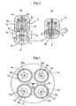
- the external electrode 3 is formed to have the shape of one columnar body.
- the multiple-integrated external electrode shown in Fig. 3(a) is one cylindrically shaped columnar external electrode, but it may also be a columnar body in the form of a square column or elliptic cylinder or the like.
- the external electrode 3 may be a columnar structure made from one columnar body formed by combining shapes which surround each container housing space with an approximately uniform thickness.
- the external electrode 3 is preferably a cylindrical body or a square column body having a square horizontal cross section.
- a plurality (four in Fig. 3 ) of housing spaces 40a, 40b, 40c, 40d which each house one of the plastic containers 7a, 7b, 7c, 7d are provided in the one columnar body serving as the external electrode 3.
- the plastic containers in each of the housing spaces four plastic containers are housed in one external electrode.
- the central axis of each of the housing spaces 40a, 40b, 40c, 40d is made parallel with the central axis x of the external electrode 3.
- the housing spaces 40a, 40b, 40c, 40d are provided side by side on the same circle S which uses the central axis x of the external electrode as a center point.
- the housing spaces are arranged so that the centers 7ax ⁇ 7dx (each of which is a point shown by ⁇ ) of the housing spaces of the plastic containers 7a ⁇ 7d are arranged on the circle S having a radius a from the center x 1 of the external electrode.
- the housing spaces 40a, 40b, 40c, 40d are preferably arranged at equal intervals on the same circle S as shown in Fig. 4 .
- an external electrode called a multiple-integrated electrode in which a plurality of housing spaces which each house one plastic container is provided in one columnar body serving as the external electrode, the central axis of each housing space is parallel with the central axis of the external electrode, and the housing spaces are arranged side by side on the same circle which uses the central axis of the external electrode as a center point.
- the multiple-integrated external electrode described in the present invention has the same function as a multiple type external electrode in which there is a plural arrangement of a combined structure of a matching box and an external electrode of the type that houses only one plastic container. Further, the multiple-integrated external electrode is integrated to make it possible to house a plurality of plastic containers inside one external electrode, and is an electrode which uses one matching box for this one integrated external electrode, and this makes it possible to reduce the high frequency power sources and matching boxes. Further, by forming the external electrode as one columnar body, the distance from the supply origin of the high frequency to the inner walls of the housing spaces can be made the shortest, and because there is no deviation of the distance between each housing space, it is possible to apply a self bias voltage uniformly to the plastic container wall surface.
- the internal electrode 9a ⁇ 9d which correspond respectively to the housing spaces 40a, 40b, 40c, 40d are provided for the one columnar body external electrode 3.
- Each of the internal electrodes is grounded, and forms a pipeline which can supply a source gas to each container.
- the internal electrodes also serve as source material supply pipes.
- a high-frequency output is introduced to a high-frequency output supply rod 30.
- the intersection point x2 between the central axis X and the bottom surface of the container lower portion external electrode 1 of the external electrode 3 shown in Fig. 2 forms a high-frequency output supply point.
- a conductive cable and a conductive metal rod are used in the high-frequency output supply rod 30.
- a high-frequency output supply rod connection contact 32 functions as a conductive contact point in the case where the container lower portion external electrode and the container upper portion external electrode are assembled at the time containers are put in and taken out.
- the high-frequency output supply point x 2 is provided in the container lower portion external electrode, but it is also possible to provided connection points distributed at four places in the container lower portion external electrode 1 near the bottom surface of each plastic container, or it is possible to make a connection or the like on the center axis X in the inside of the external electrode.
- the change of the connection point can be appropriately carried out within a range that makes it possible to generate uniform plasma inside each plastic container.
- a description was given for the case where four plastic containers are housed inside one external electrode, but it is also possible to construct an embodiment which uses an external electrode capable of housing a plurality of plastic containers other than four.
- the multiple-integrated external electrode structure by using the multiple-integrated external electrode structure, it is possible to achieve either compactness of the apparatus by reducing the number of high frequency power sources and matching boxes, or a multi-fold increase of the productivity by arranging two or more lines on the rotation support body, or it is possible to achieve both.
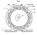
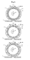
- Figs. 6 ⁇ 8 are conceptual drawings which show the arrangement relationship between the rotation support body, the external electrodes arranged on the rotation support body, and the housing spaces provided in the external electrodes, and are drawings which view the rotation support body from the front. Further, in the drawings, the case where the external electrode of the film forming chamber has a square column shape is shown, but this is the same even for a cylindrical shape or elliptic cylinder shape if the arrangement of housing spaces for the rotation support body is the same.
- Fig. 6(a) shows the case where two housing spaces 40 are provided in one external electrode 3, wherein the film forming chambers are arranged at equal intervals on the rotation support body so that the housing spaces are arranged on the same circle which uses the rotation axis of the rotation support body 41 as a center point z.
- the containers are lined up in one row from a container supply line and a rotary type apparatus up to line for removing containers that have finished film formation.
- Fig. 6(b) shows the case where two housing spaces 40 are provided in one external electrode 3, wherein one housing space 40x is arranged outside a circle s formed by each of the film forming chambers and the other housing space 40y is arranged inside the circle s when the film forming chambers are arranged on the rotation support body 41 so that the housing spaces of the external electrodes 3 are arranged in two rows in the circumferential direction of the circle s.
- two rows form the number of rows in the circumferential direction as shown in Fig. 6(b) .
- one row may be formed in the container supply line, but it is necessary to divide the line into two rows before the rotary type apparatus when the containers are inserted in the housing spaces.
- the containers that have been loaded in two rows in the rotary type apparatus are maintained as is in two rows inside the apparatus, and the containers that have finished film formation which have been removed from the rotary type apparatus preferably merge from two rows into one row.
- the housing spaces 40 are arranged in two rows in the circumferential direction of the circle s with the circle s interposed between mutually adjacent housing spaces 40, but as shown in Fig. 6(c) , the housing spaces 40 may be arranged in two rows in the circumferential direction with the circle s interposed between mutually shifted housing spaces 40.
- the housing spaces of the external electrodes 3 may be arranged in two rows in the circumferential direction of the circle s, wherein a relationship is formed so that the two housing spaces 40x, 40y of every other film forming chamber are arranged outside the circle s formed by the film forming chambers with the remaining one housing space 40z arranged inside the circle s, and the two housing spaces 40a, 40b of the adjacent film forming chambers are arranged inside the circle s with the remaining one housing space 40c arranged outside the circle s.
- the housing spaces 40 of the external electrode 3 may be arranged in two rows in the circumferential direction of the circle s, wherein the two housing spaces 40x, 40y are arranged outside the circle s formed by the film forming chambers, and the remaining two housing spaces 40a, 40b are arranged inside the circle s.
- Fig. 8(a) shows the case where the housing spaces are arranged in two rows in the circumferential direction of the circle s with the circle s interposed between mutually adjacent housing spaces when the film forming chambers are arranged on the rotation support body 41, but the housing spaces may be arranged as shown in Fig. 8(c) . Further, as shown in Fig. 8(b) , the housing spaces may be arranged in two rows in the circumferential direction with the circle s interposed between mutually shifted housing spaces.
- one row may be formed in the container supply line, but it is necessary to divide the line into two rows before the rotary type apparatus when the containers are loaded in the housing spaces.
- the containers that have been loaded in two rows in the rotary type apparatus are maintained as is in two rows inside the apparatus, and the containers that have finished film formation which have been removed from the rotary type apparatus preferably merge from two rows into one row.
- Fig. 6(a) By forming the apparatus of Fig. 6(a) , because it is possible to form a film in two plastic containers simultaneously by one high frequency power source, the number of power sources and the number of matching boxes can be reduced. Further, by forming the apparatus of Figs. 6(b)(c)(d) , Fig. 7 or Figs. 8(a)(b)(c) , it is possible to secure two or more film forming chambers proceeding through film formation at exactly the same timing in accordance with the rotation of the rotation support body, and in addition to reducing the number of power sources and the number of matching boxes, this makes it possible to double the productivity per unit time. In forming two rows, because the container loading mechanism and the container removing mechanism are not made more complex than is necessary, the number of rows achieves both an improvement in productivity and prevents the container loading mechanism and the container removing mechanism from being made more complex.
- the container according to the present invention includes a container that uses a cover or a stopper or is sealed, or a container used in an open state that does not use these.
- the size of the opening is determined in accordance with the contents.
- the plastic container includes a plastic container having a moderate stiffness and a prescribed thickness, and a plastic container formed from a sheet material that does not have stiffness. Further, this includes the cover of the container.
- the substance that is filled into the plastic container according to the present invention can be a beverage such as a carbonated beverage or a fruit juice beverage or a soft drink or the like, as well as a medicine, an agricultural chemical, or a dried food which hates moisture absorption. Further, this includes a returnable container and a one-way container.
- the resin used when forming the plastic container of the present invention can be polyethylene terephthalate (PET) resin, polyethylene terephthalate type co-polyester resin (a copolymer named PETG which uses cyclohexane de-methanol in place of ethylene glycol for the alcohol component of polyester, made by Eastman), polybutylene terephthalate resin, polyethylene naphthalate resin, polyethylene resin, polypropylene (PP) resin, cycloolefin copolymer (COC, annular olefin copolymer) resin, ionomer resin, poly-4-methylpentene-1 resin, polymethyl methacrylate resin, polystyrene resin, ethylene-vinyl alcohol copolymer resin, acrylonitrile resin, polyvinyl chloride resin, polyvinylidene chloride resin, polyamide resin, polyamideimide resin, polyacetal resin, polycarbonate resin, polysulfone resin, or ethylene tetrafluoride,
- the source gas introduction means 41 introduces a source gas supplied from a source gas generating source 20 to the inside of the plastic containers 7.
- a source gas generating source 20 is connected to the inside of the plastic containers 7.
- one side of pipelines 10, 11 is connected to the base ends of the internal electrodes 9, and the other side of the pipeline 11 is connected to a mass flow controller 19 via a vacuum valve 16.
- the other side of the mass flow controller 19 is connected to the source gas generating source 20 via a pipeline.
- the source gas generating source 20 generates a hydrocarbon gas or the like such as acetylene or the like.
- the source gas introduction means supplies a source gas to each film forming chamber.
- Source gas introduction means may be provided for each film forming chamber, but a source gas may be introduced to all of the film forming chambers by one source gas generating source.
- branching pipelines corresponding to the number of film forming chambers may be provided between the source gas generating source and the mass flow controller.
- the same number of mass flow controllers as the number of film forming chambers is provided.
- aliphatic hydrocarbons for example, aliphatic hydrocarbons, aromatic hydrocarbons, oxygen-containing hydrocarbons, nitrogen-containing hydrocarbons and the like which form a gas or liquid at room temperature are used as a source gas.
- benzene, toluene, o-xylene, m-xylene, p-xylene, cyclohexane and the like having a carbon number of 6 or higher are preferred.
- aliphatic hydrocarbons especially ethylene type hydrocarbons such as ethylene, propylene or butylene or the like, or acetylene type hydrocarbons such as acetylene, allylene or 1-butyne are preferred.
- ethylene type hydrocarbons such as ethylene, propylene or butylene or the like
- acetylene type hydrocarbons such as acetylene, allylene or 1-butyne are preferred.
- These materials may be used separately or as a gas mixture or two or more types. Further, these gases may be used in a way in which they are diluted by a noble gas such as argon or helium. Further, in the case where a silicon-containing DLC film is formed, a Si-containing hydrocarbon gas is used.
- the DLC film in the present invention is a film called an i-carbon film or an amorphous carbon hydride film (a - C : H), and also includes a hard carbon film. Further, a DLC film is an amorphous-state carbon film, and includes SP 3 bonding.
- a hydrocarbon gas such as acetylene, for example, is used as a source gas for forming the DLC film, and a Si-containing hydrocarbon gas is used as a source gas for forming a Si-containing DLC film.
- the space inside the conductive member 4b is connected to one side of a pipeline 13, and the other side of the pipeline 13 is connected to a vacuum pump 21 via a vacuum valve 18.
- the vacuum pump 21 is connected to an exhaust duct 29. Because there is a plurality of film forming chambers, exhaust may be carried out by concentrating the exhaust system at one vacuum pump, or exhaust may be carried out by allotting a plurality of vacuum pumps.
- the plastic container loading means are means wherein, for example, the lower portion external electrode 1 is opened downward with respect to the upper portion external electrode 2 in order to house containers, plastic containers are placed on the lower portion external electrode 1, and the lower portion external electrode 1 is raised to formed a sealed state by an O-ring interposed between the lower portion external electrode 1 and the upper portion external electrode 2.
- the uncoated plastic containers are supplied by a container loading handling apparatus (not shown in the drawings) which removes containers separately from a conveyor and places them on the lower portion external electrode 1.
- Pre-film-formation gas adjustment means replaces the source gas inside the plastic containers and carries out adjustment to a prescribed film forming pressure, and cooperate with the source gas introduction means and the exhaust of the vacuum pump.
- CVD film forming means are means which form a CVD film on the internal surface of the plastic containers, and cooperate with the high frequency supply means, the source gas introduction means and the exhaust means in the film forming chambers.
- the exhaust means are constructed from the vacuum valve 18, the vacuum pump 21 and the exhaust duct 29.
- Post-film-formation gas adjustment means are means which remove source gas remaining inside the film forming chambers and the plastic containers, open the inside of the plastic containers to the atmosphere after film formation, and cooperate with the exhaust means and an atmosphere open valve 17.
- Container removing means are means for removing containers from the housing spaces inside the film forming chambers, and are means wherein, for example, the lower portion external electrode 1 is opened downward with respect to the upper portion external electrode 2 in order to remove containers, and the coated plastic containers held on the lower portion external electrode 1 are transferred onto a conveyor. As shown in Fig. 1 , the coated containers are placed on a conveyor by a container removing handling apparatus (not shown in the drawings) which removes containers from the housing spaces inside the film forming chambers, and are conveyed away.
- the high frequency supply means are constructed by a fixed matching device (indicated as Tip M.B. in the drawings) provided in each external electrode, one or more high frequency power sources 15, and an automatic matching device (automatic matching box) 14 provided in each high frequency power source 15.
- a fixed matching device indicated as Tip M.B. in the drawings
- one or more high frequency power sources 15
- an automatic matching device automatic matching box
- one high frequency power source may be provided in one film forming chamber, or high frequency distribution means may be provided to distribute a high frequency supplied from a high frequency power source to multiple locations before the fixed matching device, whereby a high frequency is supplied to a plurality of external electrodes from one high frequency power source.
- switching by a high frequency relay may be carried out so that a sequential high frequency is supplied to the chamber rotated to a prescribed position corresponding to a rotation position of the rotary type rotation support body (turntable).
- a high frequency relay there should be an arrangement which makes it possible to supply a high frequency to the external electrode of each film forming chamber.
- each film forming chamber of the rotary type apparatus of Fig. 1 is constructed as shown in Fig. 2 .
- a fixed matching device is provided in each external electrode, and impedance matching of the supplied high frequency and the plasma generated inside the external electrode is carried out by a coaxial cable.
- the fixed matching device is connected to the external electrode by a copper-plated wire.
- a fixed matching device may be provided separately for each external electrode without the need for the case where the automatic matching device is miniaturized or the case where it is possible to provide the automatic matching device in some other place of the chamber.
- power may be supplied to the chamber using a coaxial pipe. In this case, it is possible to omit the fixed matching devices.
- the high frequency power source generates high frequency energy for converting source gas to plasma inside the plastic containers.
- the high frequency power source is preferably a transistor type high frequency power source, and is preferably a high frequency power source which carries out matching by a mobile frequency system or an electronic system.
- the frequency of the high frequency power source is 100 kHz ⁇ 1,000 MHz, and the industrial frequency of 13.56 MHz is used, for example.
- the wires from the automatic matching device to the fixed matching device are connected by a coaxial cable.
- the coaxial cable is given a characteristic impedance of 50 Q, for example.
- the automatic matching device adjusts the change in impedance of the coaxial cable.
- high frequency distribution means is provided in the case where the high frequency supplied from the high frequency supply means is distributed to multiple locations before the fixed matching device so that a high frequency is supplied to a plurality of external electrodes from one high frequency power source.
- the high frequency distribution means is constructed from a distribution circuit which distributes the high frequency simultaneously and evenly and a change-over switch which switches each distribution output of the distribution circuit on and off.
- the distribution circuit is a parallel type, namely, a circuit formed by a coil, a resistor and a capacitor, and is a circuit which distributes one input to a plurality of outputs.
- a cascade type circuit may be used.
- the change-over switch is a high frequency relay for switching the output of the distribution circuit on and off.
- the high frequency distribution means is provided in the case where switching is carried out by a high frequency relay so that a sequential high frequency is supplied to the chamber rotated to a prescribed position corresponding to a rotation position of the rotary type rotation support body (turntable).
- a distribution circuit is not used, and sequential switching by a high frequency relay is carried out. Further, the distribution and switching may be combined.
- the high frequency distribution means of the present embodiment it is possible to switch the high frequency supply on and off independently for each external electrode.
- the film forming chamber 6 of Fig. 2 which is a vertical cross-sectional conceptual view taken along A-A' of Fig. 3(a) has four housing spaces 40a, 40b, 40c, 40d, four plastic containers 7a, 7b, 7c, 7d and four internal electrodes 9a, 9b, 9c, 9d, but these are mentioned as the housing spaces 40, the plastic containers 7 and the internal electrodes 9 for the sake of convenience (this same notation is used below).
- the vacuum valve 16 is opened, a hydrocarbon gas is generated in the source gas generating source 20, the hydrocarbon gas is introduced inside the pipeline 22, and then the hydrocarbon gas which undergoes flow rate control by the mass flow controller 19 passes through the pipelines 10, 11 and the internal electrodes 9 which are at ground potential and is blown out from the gas blowout hole 49. In this way, the hydrocarbon gas is introduced to the inside of the plastic containers 7. Then, by balancing the controlled gas flow rate and the air exhaust performance, the pressure inside the pressure-reducing chamber of the film forming chamber 6 and the plastic containers 7 is stabilized and maintained at a pressure (e.g., about 6.6 ⁇ 665 Pa, 0.05 ⁇ 5.00 Torr) suitable for forming a DLC film.
- a pressure e.g., about 6.6 ⁇ 665 Pa, 0.05 ⁇ 5.00 Torr
- RF output e.g., 13.56 MHz
- the automatic matching device carries out impedance matching by the inductance L and the capacitance C so as to minimize the reflected waves from the entire electrode supplying output.
- the fixed matching device converts the impedance of the coaxial cable to the impedance of plasma.
- the vacuum valve 18 is opened, and the hydrocarbon gas inside the pressure-reducing chamber of the film forming chamber 6 and the plastic containers 7 is exhausted by the vacuum pump 21. Then, the vacuum valve 18 is shut, and the exhaust is terminated.
- the pressure inside the film forming chamber 6 at this time is 6.6 ⁇ 665 Pa (0.05 ⁇ 5.00 Torr). Then, the vacuum valve 17 is opened. In this way, air enters the space inside the cover 5 and the space inside the external electrode 3, whereby the inside of the film forming chamber 6 is opened to the atmosphere.
- the container removing process which removes coated containers.
- the lower portion external electrode 1 of the external electrode 3 is placed in a removed state from the upper portion external electrode 2.
- the plastic containers 7 housed in the housing spaces inside the upper portion external electrode 2 are removed from the lower side of the upper portion external electrode 2 by the container removing handling apparatus (not shown in the drawings).
- the coated containers (the containers that have finished film formation of Fig. 1 ) are placed on a conveyor (not shown in the drawings) and conveyed away.
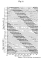
- the method preferably carries out the manufacturing cycle for each film forming chamber a plurality of times at fixed intervals. For example, the method is carried out at the timing shown in Fig. 11 or Fig. 12 .
- Fig. 11 shows the case where there are 32 film forming chambers, and these are supplied with a high frequency by two high frequency power sources (A and B). Further, Fig.
- FIG. 12 shows the case where there are 32 film forming chambers, and these are supplied with a high frequency by four high frequency power sources (A, B, C and D).
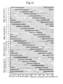
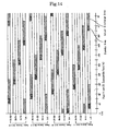
- FIG. 13 or Fig. 14 it is possible to form units by collecting several film forming chambers, and the manufacturing cycle may be carried out at fixed intervals.
- Fig. 13 shows the case where there are 32 film forming chambers, and these are supplied with a high frequency by two high frequency power sources (A and B).
- Fig. 14 shows the case where there are 32 film forming chambers, and these are supplied with a high frequency by four high frequency power sources (A, B, C and D).
- the numbers 1 ⁇ 32 are numbers which are sequentially applied to the film forming chambers on the rotation support body.
- a prescribed position of the rotation support body is made 0° degrees, and the rotation degree which uses this 0° as a reference forms the horizontal axis of the drawings.
- a uniform high frequency is preferably supplied to each housing space and each film forming chamber.
- the number of chambers, the number of high frequency power sources and the number of structural components and the like may be appropriately changed in accordance with the required performance of the apparatus.
- a PET bottle for beverages was used as the container having a thin film formed on the inside, but it is also possible to use containers used for other uses.
- a DLC film or a Si-containing DLC film is the thin film formed by the CVD film forming apparatus, but it is also possible to use the film forming apparatus described above when forming other thin films inside containers.
- the film thickness of the DLC film is formed to be 0.003 ⁇ 5 ⁇ m.
Claims (9)
- Appareil de formation de film CVD du type rotatif pour la production de masse, comportant une chambre (6) de formation de film réalisée en prévoyant un corps colonnaire servant d'électrode externe (3) qui présente une pluralité d'espaces de logement (40) pour loger un récipient en plastique (7) respectif dans un des espaces de logement (40), de telle sorte que l'axe médian de chacun des espaces de logement (40) est parallèle à l'axe médian de l'électrode externe (3) et les espaces de logement (40) sont agencés les uns à côté des autres sur le même cercle qui utilise l'axe médian de l'électrode externe (3) comme point central (X1), en prévoyant des électrodes internes (9) qui peuvent être agencées de manière à être librement insérées depuis le tronçon d'ouverture dans l'intérieur des récipients en plastique (7) chargés dans chacun des espaces de logement (40), en prévoyant un élément isolant (4a) pour la réalisation d'un état isolant entre les électrodes internes (9) et l'électrode externe (3) lorsque les électrodes internes (9) sont insérées dans les récipients en plastique (7), et en prévoyant un couvercle (4b) qui est fermé pour réduire la pression à l'intérieur des espaces de logement (40), un pluralité des chambres (6) de formation de film étant agencées sur un corps support rotatif (41) à intervalles égaux dans un état circulaire, des moyens d'introduction (49) de gaz de source étant prévus, lesquels introduisent un gaz de source qui est transformé en plasma à l'intérieur des récipients en plastique (7) logés dans chacune des chambres (6) de formation de film, et des moyens d'alimentation (14, 15) en haute fréquence qui alimentent l'électrode externe (3) de chacune des chambres (6) de formation de film en haute fréquence étant prévus pour former un film CVD (dépôt chimique en phase vapeur) sur les surfaces intérieures des récipients en plastique (7).
- Dispositif de formation de film CVD de type rotatif pour la production de masse selon la revendication 1, dans lequel les espaces de logement (40) sont agencés les uns à côté des autres à intervalles égaux sur le même cercle qui utilise l'axe médian de l'électrode externe (3) comme point central.
- Dispositif de formation de film CVD du type rotatif pour la production de masse selon la revendication 1 ou 2, dans lequel deux espaces de logement (40) sont prévus dans une électrode externe, et les chambres (6) de formation de film sont agencées à intervalles égaux sur le corps support rotatif (41) de telle sorte que les espaces de logement (40) sont agencés sur le même cercle qui utilise l'axe de rotation du corps support rotatif (41) comme point central.
- Dispositif de formation de film CVD du type rotatif pour la production de masse selon la revendication 1 ou 2, dans lequel deux espaces de logement (40x, 40y) sont prévus dans une électrode externe (3), et lorsque les chambres (6) de formation de film sont agencées sur le corps support rotatif (41), un espace de logement (40x) est agencé à l'extérieur d'un cercle formé par chacune des chambres (6) de formation de film et l'autre espace de logement (40y) est agencé à l'intérieur du cercle, grâce à quoi les espaces de logement (40x, 40y) des électrodes externes sont agencés en deux rangs dans le sens circonférentiel du cercle.
- Dispositif de formation de film CVD du type rotatif pour la production de masse selon la revendication 1 ou 2, dans lequel trois espaces de logement (40a, 40b, 40c ; 40x, 40y, 40z) sont prévus dans une électrode externe (3), et lorsque les chambres (6) de formation de film sont agencées sur le corps support rotatif (41), les espaces de logement (40a, 40b, 40c; 40x, 40y, 40z) sont agencés de telle sorte que deux espaces de logement (40x, 40y) sont agencés à l'extérieur d'un cercle formé par les chambres (6) de formation de film, et l'espace de logement restant (40z) est agencé à l'intérieur du cercle dans chacune des autres chambres (6) de formation de film, tandis que deux espaces de logement (40a, 40b) sont agencés à l'intérieur du cercle et l'espace de logement restant (40c) est agencé à l'extérieur du cercle dans chaque chambre (6) de formation de film adjacente à chacune des autres chambres de formation de film, grâce à quoi les espaces de logement (40a, 40b, 40c ; 40x, 40y, 40z) des électrodes externes (3) sont agencés en deux rangs dans le sens circonférentiel du cercle.
- Dispositif de formation de film CVD du type rotatif pour la production de masse selon la revendication 1 ou 2, dans lequel quatre espaces de logement (40a, 40b, 40x, 40y) sont prévus dans une électrode externe (3), et lorsque les chambres (6) de formation de film sont agencées sur le corps support rotatif (41), deux espaces de logement (40x, 40y) sont agencés à l'extérieur d'un cercle formé par les chambres (6) de formation de film, et les deux autres espaces de logement (40a, 40b) sont agencés à l'intérieur du cercle, grâce à quoi les espaces de logement (40a, 40b, 40x, 40y) des électrodes externes sont agencés en deux rangs dans le sens circonférentiel du cercle.
- Dispositif de formation de film CVD du type rotatif pour la production de masse selon la revendication 4 ou 6, dans lequel lorsque les chambres (6) de formation de film sont agencées sur le corps support rotatif (41), les espaces de logement (40) sont agencés en deux rangs dans le sens circonférentiel du cercle, le cercle étant interposé entre des espaces de logement (40) adjacents les uns par rapport aux autres, ou les espaces de logement (40) sont agencés en deux rangs dans le sens circonférentiel, le cercle étant interposé entre des espaces de logement (40) décalés les uns par rapport aux autres.
- Procédé de formation d'un film CVD sur les surfaces intérieures de récipients en plastique (7) en utilisant un dispositif de formation de film CVD du type rotatif pour la production de masse selon l'une des revendications 1 à 7, dans lequel une procédure de chargement de récipients, dans laquelle les récipients en plastique (7) sont chargés dans les chambres (6) de formation de film en logeant les récipients en plastique (7) dans les espaces de logement (40), une procédure d'ajustage de gaz de préformation de film, dans laquelle l'intérieur des récipients en plastique (7) est remplacé par un gaz de source ajusté à une pression prescrite de formation de film, une procédure de formation de film CVD, dans laquelle le gaz de source est transformé en plasma et un film CVD est formé sur les surfaces intérieures des récipients en plastique (7), une procédure d'ajustage de gaz de postformation de film, dans laquelle l'intérieur des récipients en plastique (7) revêtus est ouvert à l'atmosphère, et une procédure de retrait de récipients, dans laquelle les récipients (7) revêtus sont extraits des chambres (6) de formation de film sont exécutées pendant le temps durant lequel le corps support rotatif (41) effectue une rotation à une vitesse fixe.
- Procédé selon la revendication 8, dans lequel un gaz d'hydrocarbure contenant du Si est utilisé comme gaz de source, et un film DLC est formé comme film CVD.
Applications Claiming Priority (3)
| Application Number | Priority Date | Filing Date | Title |
|---|---|---|---|
| JP2002183309 | 2002-06-24 | ||
| JP2002183309A JP4149748B2 (ja) | 2002-06-24 | 2002-06-24 | ロータリー型量産用cvd成膜装置及びプラスチック容器内表面へのcvd膜成膜方法 |
| PCT/JP2003/007797 WO2004001095A1 (fr) | 2002-06-24 | 2003-06-19 | Dispositif de type rotatif destine a la production en grandes quantites de pellicules de depot chimique en phase vapeur et procede de production de pellicules de depot chimique en phase vapeur sur une surface dans un contenant plastique |
Publications (3)
| Publication Number | Publication Date |
|---|---|
| EP1516941A1 EP1516941A1 (fr) | 2005-03-23 |
| EP1516941A4 EP1516941A4 (fr) | 2009-01-07 |
| EP1516941B1 true EP1516941B1 (fr) | 2012-02-22 |
Family
ID=29996676
Family Applications (1)
| Application Number | Title | Priority Date | Filing Date |
|---|---|---|---|
| EP03760909A Expired - Lifetime EP1516941B1 (fr) | 2002-06-24 | 2003-06-19 | Dispositif de type rotatif destine a la production en grandes quantites de pellicules de depot chimique en phase vapeur et procede de production de pellicules de depot chimique en phase vapeur sur une surface dans un contenant plastique |
Country Status (9)
| Country | Link |
|---|---|
| US (1) | US7603962B2 (fr) |
| EP (1) | EP1516941B1 (fr) |
| JP (1) | JP4149748B2 (fr) |
| KR (1) | KR101089535B1 (fr) |
| CN (1) | CN100350072C (fr) |
| AT (1) | ATE546564T1 (fr) |
| AU (1) | AU2003244311A1 (fr) |
| HK (1) | HK1080121B (fr) |
| WO (1) | WO2004001095A1 (fr) |
Families Citing this family (19)
| Publication number | Priority date | Publication date | Assignee | Title |
|---|---|---|---|---|
| WO2000071780A1 (fr) * | 1999-05-19 | 2000-11-30 | Mitsubishi Shoji Plastics Corporation | Film dlc, contenant en plastique recouvert de dlc, et procede et appareil de fabrication de contenant en plastique recouvert de dlc |
| CN100335376C (zh) * | 2002-04-26 | 2007-09-05 | 北海制罐株式会社 | 内表面经涂覆的塑料容器及其制造方法 |
| JP4604541B2 (ja) * | 2004-04-16 | 2011-01-05 | 凸版印刷株式会社 | 成膜装置及び成膜方法 |
| FR2889204B1 (fr) * | 2005-07-26 | 2007-11-30 | Sidel Sas | Appareil pour le depot pecvd d'une couche barriere interne sur un recipient, comprenant une ligne de gaz isolee par electrovanne |
| JP4611170B2 (ja) * | 2005-10-19 | 2011-01-12 | 三菱重工業株式会社 | バリヤ膜形成装置 |
| FR2907037B1 (fr) * | 2006-10-13 | 2009-01-09 | Sidel Participations | Installation de depot,au moyen d'un plasma micro-ondes,d'un revetement barriere interne dans des recipients thermoplastiques |
| FR2907351B1 (fr) * | 2006-10-18 | 2009-02-06 | Sidel Participations | Machine de traitement de recipients par plasma,comprenant des circuits de depressurisation et de pressurisation decales |
| FR2929295A1 (fr) * | 2008-03-25 | 2009-10-02 | Becton Dickinson France Soc Pa | Appareil pour le traitement par plasma de corps creux |
| DE102009001343A1 (de) | 2009-03-05 | 2010-09-09 | Coiffeur Consulting Team Cosmetics Gmbh | Kosmetisches Haarstimulierungs-Set und Verfahren zur Stimulierung des Haarwachstums |
| DE102010023119A1 (de) * | 2010-06-07 | 2011-12-22 | Khs Corpoplast Gmbh | Vorrichtung zur Plasmabehandlung von Werkstücken |
| JP5603201B2 (ja) * | 2010-10-27 | 2014-10-08 | サントリーホールディングス株式会社 | 樹脂製容器の表面改質方法および樹脂製容器の表面改質装置 |
| DE102012204690A1 (de) * | 2012-03-23 | 2013-09-26 | Krones Ag | Vorrichtung zum Plasmabeschichten von Füllgutbehältern, wie Flaschen |
| JP6093552B2 (ja) * | 2012-11-08 | 2017-03-08 | 日精エー・エス・ビー機械株式会社 | 樹脂容器用コーティング装置 |
| WO2014103677A1 (fr) * | 2012-12-26 | 2014-07-03 | 麒麟麦酒株式会社 | Dispositif de dépôt de film mince |
| WO2014112533A1 (fr) * | 2013-01-18 | 2014-07-24 | 日精エー・エス・ビー機械株式会社 | Dispositif de revêtement pour récipient en résine et système de fabrication pour récipient en résine |
| ES2701061T5 (es) | 2014-10-22 | 2022-05-09 | Crescendo Biologics Ltd | Ratones transgénicos |
| CN105228330B (zh) * | 2015-09-01 | 2018-09-14 | 沈阳拓荆科技有限公司 | 一种射频等离子体设备匹配器 |
| CA3189169A1 (fr) * | 2020-08-12 | 2022-02-17 | Ahmad TAHA | Procede de depot chimique en phase vapeur assiste par plasma pulse, systeme et recipients revetus |
| DE102021120056A1 (de) * | 2021-08-02 | 2023-02-02 | Khs Gmbh | Verfahren zum Beschichten von Behältern aus Kunststoff |
Citations (1)
| Publication number | Priority date | Publication date | Assignee | Title |
|---|---|---|---|---|
| EP1010773A1 (fr) * | 1997-02-19 | 2000-06-21 | Kirin Beer Kabushiki Kaisha | Procede et appareil pour produire un recipient plastique presentant un pelliculage en carbone |
Family Cites Families (10)
| Publication number | Priority date | Publication date | Assignee | Title |
|---|---|---|---|---|
| US3616458A (en) * | 1969-12-31 | 1971-10-26 | Yosimaro Moriya | Apparatus for activating internal surfaces of plastic hollow articles |
| FR2592874B1 (fr) * | 1986-01-14 | 1990-08-03 | Centre Nat Rech Scient | Procede pour tremper un objet en verre ou vitreux et objet ainsi trempe |
| US5565248A (en) * | 1994-02-09 | 1996-10-15 | The Coca-Cola Company | Method and apparatus for coating hollow containers through plasma-assisted deposition of an inorganic substance |
| JP2788412B2 (ja) | 1994-08-11 | 1998-08-20 | 麒麟麦酒株式会社 | 炭素膜コーティングプラスチック容器の製造装置および製造方法 |
| JP3115252B2 (ja) | 1997-03-14 | 2000-12-04 | 麒麟麦酒株式会社 | 炭素膜コーティングプラスチック容器の製造装置および製造方法 |
| KR100390578B1 (ko) * | 1998-12-17 | 2003-12-18 | 제일모직주식회사 | 고굴절율 전도성 고분자 박막 투명 필름 코팅액 조성물 |
| JP2001335945A (ja) | 2000-05-24 | 2001-12-07 | Mitsubishi Shoji Plast Kk | Cvd成膜装置及びcvd成膜方法 |
| JP2002121667A (ja) | 2000-10-12 | 2002-04-26 | Mitsubishi Shoji Plast Kk | プラスチック容器内へのdlc膜連続成膜装置及び連続成膜方法 |
| CN1235771C (zh) * | 2000-12-25 | 2006-01-11 | 三菱商事塑料株式会社 | 用于制造类金刚石薄膜涂敷的塑料容器的设备及其制造方法 |
| JP4067817B2 (ja) * | 2001-12-07 | 2008-03-26 | 日精エー・エス・ビー機械株式会社 | 容器のコーティング装置 |
-
2002
- 2002-06-24 JP JP2002183309A patent/JP4149748B2/ja not_active Expired - Fee Related
-
2003
- 2003-06-19 WO PCT/JP2003/007797 patent/WO2004001095A1/fr active Application Filing
- 2003-06-19 AU AU2003244311A patent/AU2003244311A1/en not_active Abandoned
- 2003-06-19 CN CNB038148919A patent/CN100350072C/zh not_active Expired - Fee Related
- 2003-06-19 AT AT03760909T patent/ATE546564T1/de active
- 2003-06-19 KR KR1020047020694A patent/KR101089535B1/ko active IP Right Grant
- 2003-06-19 US US10/516,732 patent/US7603962B2/en not_active Expired - Fee Related
- 2003-06-19 EP EP03760909A patent/EP1516941B1/fr not_active Expired - Lifetime
-
2006
- 2006-01-04 HK HK06100078.9A patent/HK1080121B/zh not_active IP Right Cessation
Patent Citations (1)
| Publication number | Priority date | Publication date | Assignee | Title |
|---|---|---|---|---|
| EP1010773A1 (fr) * | 1997-02-19 | 2000-06-21 | Kirin Beer Kabushiki Kaisha | Procede et appareil pour produire un recipient plastique presentant un pelliculage en carbone |
Also Published As
| Publication number | Publication date |
|---|---|
| WO2004001095A1 (fr) | 2003-12-31 |
| US20050155553A1 (en) | 2005-07-21 |
| CN100350072C (zh) | 2007-11-21 |
| AU2003244311A8 (en) | 2004-01-06 |
| HK1080121A1 (en) | 2006-04-21 |
| CN1662675A (zh) | 2005-08-31 |
| KR20050023316A (ko) | 2005-03-09 |
| HK1080121B (zh) | 2008-03-28 |
| AU2003244311A1 (en) | 2004-01-06 |
| EP1516941A4 (fr) | 2009-01-07 |
| KR101089535B1 (ko) | 2011-12-05 |
| JP4149748B2 (ja) | 2008-09-17 |
| US7603962B2 (en) | 2009-10-20 |
| EP1516941A1 (fr) | 2005-03-23 |
| JP2004027271A (ja) | 2004-01-29 |
| ATE546564T1 (de) | 2012-03-15 |
Similar Documents
| Publication | Publication Date | Title |
|---|---|---|
| EP1516941B1 (fr) | Dispositif de type rotatif destine a la production en grandes quantites de pellicules de depot chimique en phase vapeur et procede de production de pellicules de depot chimique en phase vapeur sur une surface dans un contenant plastique | |
| US6294226B1 (en) | Method and apparatus for producing plastic container having carbon film coating | |
| US6924001B2 (en) | Production device for DLC film-coated plastic container and production method therefor | |
| US7926446B2 (en) | Multi-place coating apparatus and process for plasma coating | |
| US20060096540A1 (en) | Apparatus to manufacture semiconductor | |
| CN101636523A (zh) | 阻隔膜形成装置、阻隔膜形成方法及阻隔膜被覆容器 | |
| CN101994101A (zh) | 成膜装置和成膜方法 | |
| KR20040106292A (ko) | 플라즈마 cvd 막 형성 장치 및 cvd 막 코팅플라스틱용기의 제조 방법 | |
| JP2001335945A (ja) | Cvd成膜装置及びcvd成膜方法 | |
| JP3679067B2 (ja) | ロータリー型量産用cvd成膜装置及びプラスチック容器内表面へのcvd膜成膜方法 | |
| CN100436642C (zh) | 用于制造包覆有dlc薄膜的塑料容器的设备 | |
| US20040146667A1 (en) | Manufacturing device for dlc film coated plastic container, dlc film coated plastic container, and method of manufacturing the dlc film coated plastic container | |
| JP2004002905A6 (ja) | ロータリー型量産用cvd成膜装置及びプラスチック容器内表面へのcvd膜成膜方法 | |
| US20030110822A1 (en) | Gas-barrier synthetic resin vessel, device for producing the same, and article-received gas-barrier synthetic resin vessel | |
| WO2005035825A1 (fr) | Dispositif de formation de film par cvd et procede de fabrication d'un contenant plastique a revetement de film fabrique par cvd | |
| JP2001335947A (ja) | Cvd成膜装置及びcvd成膜方法 | |
| US20040146666A1 (en) | Moisture and gas barrier plastic container with partition plates, and device for method manufacturing the plastic container | |
| JP3746761B2 (ja) | プラスチック容器内面へのバリヤ膜形成装置および内面バリヤ膜被覆プラスチック容器の製造方法 | |
| CN100387492C (zh) | 对塑料容器内面形成碳膜的装置及内面覆盖碳膜的塑料容器的制造方法 | |
| JP2004124134A (ja) | 薄膜成膜方法および薄膜成膜装置 | |
| AU776224B2 (en) | Apparatus and method for manufacturing plastic container coated with carbon film | |
| KR100976104B1 (ko) | Dlc막 코팅 플라스틱 용기의 제조 장치 | |
| JP2005105306A (ja) | 真空成膜装置およびその容器搬送方法 | |
| JP2004250750A (ja) | 筒状プラスチック構造物内面への薄膜成膜装置 |
Legal Events
| Date | Code | Title | Description |
|---|---|---|---|
| PUAI | Public reference made under article 153(3) epc to a published international application that has entered the european phase |
Free format text: ORIGINAL CODE: 0009012 |
|
| 17P | Request for examination filed |
Effective date: 20041214 |
|
| AK | Designated contracting states |
Kind code of ref document: A1 Designated state(s): AT BE BG CH CY CZ DE DK EE ES FI FR GB GR HU IE IT LI LU MC NL PT RO SE SI SK TR |
|
| AX | Request for extension of the european patent |
Extension state: AL LT LV MK |
|
| DAX | Request for extension of the european patent (deleted) | ||
| A4 | Supplementary search report drawn up and despatched |
Effective date: 20081210 |
|
| RAP1 | Party data changed (applicant data changed or rights of an application transferred) |
Owner name: YOUTEC CO., LTD. Owner name: MITSUBISHI SHOJI PLASTICS CORPORATION |
|
| 17Q | First examination report despatched |
Effective date: 20100803 |
|
| GRAP | Despatch of communication of intention to grant a patent |
Free format text: ORIGINAL CODE: EPIDOSNIGR1 |
|
| RIN1 | Information on inventor provided before grant (corrected) |
Inventor name: HAMA, KENICHI,C/O MITSUBISHI SHOJI PLASTICS CORPOR Inventor name: KAWABE, TAKEHARU,C/O YOUTEC CO., LTD Inventor name: KAGE, TSUYOSHI,C/O MITSUBISHI SHOJI PLASTICS CORPO Inventor name: KOBAYASHI, TAKUMI,C/O YOUTEC CO., LTD |
|
| GRAS | Grant fee paid |
Free format text: ORIGINAL CODE: EPIDOSNIGR3 |
|
| GRAA | (expected) grant |
Free format text: ORIGINAL CODE: 0009210 |
|
| AK | Designated contracting states |
Kind code of ref document: B1 Designated state(s): AT BE BG CH CY CZ DE DK EE ES FI FR GB GR HU IE IT LI LU MC NL PT RO SE SI SK TR |
|
| RAP1 | Party data changed (applicant data changed or rights of an application transferred) |
Owner name: MITSUBISHI SHOJI PLASTICS CORPORATION Owner name: YOUTEC CO., LTD. |
|
| REG | Reference to a national code |
Ref country code: GB Ref legal event code: FG4D |
|
| RIN1 | Information on inventor provided before grant (corrected) |
Inventor name: KAGE, TSUYOSHI,C/O MITSUBISHI SHOJI PLASTICS CORPO Inventor name: KAWABE, TAKEHARU,C/O YOUTEC CO., LTD Inventor name: KOBAYASHI, TAKUMI,C/O YOUTEC CO., LTD Inventor name: HAMA, KENICHI,C/O MITSUBISHI SHOJI PLASTICS CORPOR |
|
| REG | Reference to a national code |
Ref country code: CH Ref legal event code: EP |
|
| REG | Reference to a national code |
Ref country code: AT Ref legal event code: REF Ref document number: 546564 Country of ref document: AT Kind code of ref document: T Effective date: 20120315 |
|
| REG | Reference to a national code |
Ref country code: IE Ref legal event code: FG4D |
|
| REG | Reference to a national code |
Ref country code: DE Ref legal event code: R096 Ref document number: 60340082 Country of ref document: DE Effective date: 20120412 |
|
| REG | Reference to a national code |
Ref country code: NL Ref legal event code: VDEP Effective date: 20120222 |
|
| PG25 | Lapsed in a contracting state [announced via postgrant information from national office to epo] |
Ref country code: NL Free format text: LAPSE BECAUSE OF FAILURE TO SUBMIT A TRANSLATION OF THE DESCRIPTION OR TO PAY THE FEE WITHIN THE PRESCRIBED TIME-LIMIT Effective date: 20120222 |
|
| PG25 | Lapsed in a contracting state [announced via postgrant information from national office to epo] |
Ref country code: FI Free format text: LAPSE BECAUSE OF FAILURE TO SUBMIT A TRANSLATION OF THE DESCRIPTION OR TO PAY THE FEE WITHIN THE PRESCRIBED TIME-LIMIT Effective date: 20120222 Ref country code: GR Free format text: LAPSE BECAUSE OF FAILURE TO SUBMIT A TRANSLATION OF THE DESCRIPTION OR TO PAY THE FEE WITHIN THE PRESCRIBED TIME-LIMIT Effective date: 20120523 Ref country code: BE Free format text: LAPSE BECAUSE OF FAILURE TO SUBMIT A TRANSLATION OF THE DESCRIPTION OR TO PAY THE FEE WITHIN THE PRESCRIBED TIME-LIMIT Effective date: 20120222 Ref country code: PT Free format text: LAPSE BECAUSE OF FAILURE TO SUBMIT A TRANSLATION OF THE DESCRIPTION OR TO PAY THE FEE WITHIN THE PRESCRIBED TIME-LIMIT Effective date: 20120622 |
|
| REG | Reference to a national code |
Ref country code: AT Ref legal event code: MK05 Ref document number: 546564 Country of ref document: AT Kind code of ref document: T Effective date: 20120222 |
|
| PG25 | Lapsed in a contracting state [announced via postgrant information from national office to epo] |
Ref country code: CY Free format text: LAPSE BECAUSE OF FAILURE TO SUBMIT A TRANSLATION OF THE DESCRIPTION OR TO PAY THE FEE WITHIN THE PRESCRIBED TIME-LIMIT Effective date: 20120222 |
|
| PG25 | Lapsed in a contracting state [announced via postgrant information from national office to epo] |
Ref country code: CZ Free format text: LAPSE BECAUSE OF FAILURE TO SUBMIT A TRANSLATION OF THE DESCRIPTION OR TO PAY THE FEE WITHIN THE PRESCRIBED TIME-LIMIT Effective date: 20120222 Ref country code: DK Free format text: LAPSE BECAUSE OF FAILURE TO SUBMIT A TRANSLATION OF THE DESCRIPTION OR TO PAY THE FEE WITHIN THE PRESCRIBED TIME-LIMIT Effective date: 20120222 Ref country code: RO Free format text: LAPSE BECAUSE OF FAILURE TO SUBMIT A TRANSLATION OF THE DESCRIPTION OR TO PAY THE FEE WITHIN THE PRESCRIBED TIME-LIMIT Effective date: 20120222 Ref country code: EE Free format text: LAPSE BECAUSE OF FAILURE TO SUBMIT A TRANSLATION OF THE DESCRIPTION OR TO PAY THE FEE WITHIN THE PRESCRIBED TIME-LIMIT Effective date: 20120222 Ref country code: SI Free format text: LAPSE BECAUSE OF FAILURE TO SUBMIT A TRANSLATION OF THE DESCRIPTION OR TO PAY THE FEE WITHIN THE PRESCRIBED TIME-LIMIT Effective date: 20120222 Ref country code: SE Free format text: LAPSE BECAUSE OF FAILURE TO SUBMIT A TRANSLATION OF THE DESCRIPTION OR TO PAY THE FEE WITHIN THE PRESCRIBED TIME-LIMIT Effective date: 20120222 |
|
| PG25 | Lapsed in a contracting state [announced via postgrant information from national office to epo] |
Ref country code: IT Free format text: LAPSE BECAUSE OF FAILURE TO SUBMIT A TRANSLATION OF THE DESCRIPTION OR TO PAY THE FEE WITHIN THE PRESCRIBED TIME-LIMIT Effective date: 20120222 Ref country code: SK Free format text: LAPSE BECAUSE OF FAILURE TO SUBMIT A TRANSLATION OF THE DESCRIPTION OR TO PAY THE FEE WITHIN THE PRESCRIBED TIME-LIMIT Effective date: 20120222 |
|
| PLBE | No opposition filed within time limit |
Free format text: ORIGINAL CODE: 0009261 |
|
| STAA | Information on the status of an ep patent application or granted ep patent |
Free format text: STATUS: NO OPPOSITION FILED WITHIN TIME LIMIT |
|
| 26N | No opposition filed |
Effective date: 20121123 |
|
| PG25 | Lapsed in a contracting state [announced via postgrant information from national office to epo] |
Ref country code: AT Free format text: LAPSE BECAUSE OF FAILURE TO SUBMIT A TRANSLATION OF THE DESCRIPTION OR TO PAY THE FEE WITHIN THE PRESCRIBED TIME-LIMIT Effective date: 20120222 Ref country code: MC Free format text: LAPSE BECAUSE OF NON-PAYMENT OF DUE FEES Effective date: 20120630 |
|
| REG | Reference to a national code |
Ref country code: CH Ref legal event code: PL |
|
| REG | Reference to a national code |
Ref country code: CH Ref legal event code: PL |
|
| GBPC | Gb: european patent ceased through non-payment of renewal fee |
Effective date: 20120619 |
|
| REG | Reference to a national code |
Ref country code: DE Ref legal event code: R097 Ref document number: 60340082 Country of ref document: DE Effective date: 20121123 |
|
| REG | Reference to a national code |
Ref country code: IE Ref legal event code: MM4A |
|
| PG25 | Lapsed in a contracting state [announced via postgrant information from national office to epo] |
Ref country code: ES Free format text: LAPSE BECAUSE OF FAILURE TO SUBMIT A TRANSLATION OF THE DESCRIPTION OR TO PAY THE FEE WITHIN THE PRESCRIBED TIME-LIMIT Effective date: 20120602 Ref country code: CH Free format text: LAPSE BECAUSE OF NON-PAYMENT OF DUE FEES Effective date: 20120630 Ref country code: GB Free format text: LAPSE BECAUSE OF NON-PAYMENT OF DUE FEES Effective date: 20120619 Ref country code: LI Free format text: LAPSE BECAUSE OF NON-PAYMENT OF DUE FEES Effective date: 20120630 Ref country code: IE Free format text: LAPSE BECAUSE OF NON-PAYMENT OF DUE FEES Effective date: 20120619 |
|
| PG25 | Lapsed in a contracting state [announced via postgrant information from national office to epo] |
Ref country code: BG Free format text: LAPSE BECAUSE OF FAILURE TO SUBMIT A TRANSLATION OF THE DESCRIPTION OR TO PAY THE FEE WITHIN THE PRESCRIBED TIME-LIMIT Effective date: 20120522 |
|
| PG25 | Lapsed in a contracting state [announced via postgrant information from national office to epo] |
Ref country code: TR Free format text: LAPSE BECAUSE OF FAILURE TO SUBMIT A TRANSLATION OF THE DESCRIPTION OR TO PAY THE FEE WITHIN THE PRESCRIBED TIME-LIMIT Effective date: 20120222 |
|
| PG25 | Lapsed in a contracting state [announced via postgrant information from national office to epo] |
Ref country code: LU Free format text: LAPSE BECAUSE OF NON-PAYMENT OF DUE FEES Effective date: 20120619 |
|
| PG25 | Lapsed in a contracting state [announced via postgrant information from national office to epo] |
Ref country code: HU Free format text: LAPSE BECAUSE OF FAILURE TO SUBMIT A TRANSLATION OF THE DESCRIPTION OR TO PAY THE FEE WITHIN THE PRESCRIBED TIME-LIMIT Effective date: 20030619 |
|
| REG | Reference to a national code |
Ref country code: FR Ref legal event code: PLFP Year of fee payment: 13 |
|
| REG | Reference to a national code |
Ref country code: FR Ref legal event code: PLFP Year of fee payment: 14 |
|
| REG | Reference to a national code |
Ref country code: FR Ref legal event code: PLFP Year of fee payment: 15 |
|
| REG | Reference to a national code |
Ref country code: FR Ref legal event code: PLFP Year of fee payment: 16 |
|
| REG | Reference to a national code |
Ref country code: DE Ref legal event code: R082 Ref document number: 60340082 Country of ref document: DE Representative=s name: PRINZ & PARTNER MBB PATENTANWAELTE RECHTSANWAE, DE Ref country code: DE Ref legal event code: R081 Ref document number: 60340082 Country of ref document: DE Owner name: ADVANCED MATERIAL TECHNOLOGIES, INC., JP Free format text: FORMER OWNERS: MITSUBISHI SHOJI PLASTICS CORP., TOKIO/TOKYO, JP; YOUTEC CO. LTD., NAGAREYAMA, JP Ref country code: DE Ref legal event code: R081 Ref document number: 60340082 Country of ref document: DE Owner name: MITSUBISHI SHOJI PLASTICS CORP., JP Free format text: FORMER OWNERS: MITSUBISHI SHOJI PLASTICS CORP., TOKIO/TOKYO, JP; YOUTEC CO. LTD., NAGAREYAMA, JP |
|
| PGFP | Annual fee paid to national office [announced via postgrant information from national office to epo] |
Ref country code: DE Payment date: 20200625 Year of fee payment: 18 Ref country code: FR Payment date: 20200619 Year of fee payment: 18 |
|
| REG | Reference to a national code |
Ref country code: DE Ref legal event code: R119 Ref document number: 60340082 Country of ref document: DE |
|
| PG25 | Lapsed in a contracting state [announced via postgrant information from national office to epo] |
Ref country code: DE Free format text: LAPSE BECAUSE OF NON-PAYMENT OF DUE FEES Effective date: 20220101 |
|
| PG25 | Lapsed in a contracting state [announced via postgrant information from national office to epo] |
Ref country code: FR Free format text: LAPSE BECAUSE OF NON-PAYMENT OF DUE FEES Effective date: 20210630 |