EP1516849A2 - Kran - Google Patents
Kran Download PDFInfo
- Publication number
- EP1516849A2 EP1516849A2 EP04020892A EP04020892A EP1516849A2 EP 1516849 A2 EP1516849 A2 EP 1516849A2 EP 04020892 A EP04020892 A EP 04020892A EP 04020892 A EP04020892 A EP 04020892A EP 1516849 A2 EP1516849 A2 EP 1516849A2
- Authority
- EP
- European Patent Office
- Prior art keywords
- crane
- auxiliary frame
- erecting
- ballast
- crane according
- Prior art date
- Legal status (The legal status is an assumption and is not a legal conclusion. Google has not performed a legal analysis and makes no representation as to the accuracy of the status listed.)
- Granted
Links
Images
Classifications
-
- B—PERFORMING OPERATIONS; TRANSPORTING
- B66—HOISTING; LIFTING; HAULING
- B66C—CRANES; LOAD-ENGAGING ELEMENTS OR DEVICES FOR CRANES, CAPSTANS, WINCHES, OR TACKLES
- B66C23/00—Cranes comprising essentially a beam, boom, or triangular structure acting as a cantilever and mounted for translatory of swinging movements in vertical or horizontal planes or a combination of such movements, e.g. jib-cranes, derricks, tower cranes
- B66C23/62—Constructional features or details
- B66C23/72—Counterweights or supports for balancing lifting couples
- B66C23/74—Counterweights or supports for balancing lifting couples separate from jib
Definitions
- the present invention relates to a crane with an about an upright axis rotatable superstructure, one on the superstructure about a horizontal axis tiltable articulated boom, a luffing device for rocking up and down the boom, and a counteracting the moment of the boom operating ballast.
- the present invention is therefore based on the object, an improved Crane of the type mentioned, the disadvantages of the prior art Avoiding technology and the latter develops in an advantageous manner.
- the erection of very long boom combinations be achieved without to provide redundant ballast for the operation.
- the crane is thus characterized in that a erecting auxiliary frame is provided, according to the superstructure and / or the operating ballast cantilevered at the rear and with a righting ballast for erecting the boom is connectable.
- the Aufrichteangesrahmen can thereby on the Rear of the superstructure or the attached operating ballast attached be that from the opposite side of the boom from the boom protrudes to the rear and has an extended lever arm, where the Rearing auxiliary ballast can be attached.
- the righting help ballast becomes special attached for erecting the boom on the erecting auxiliary frame and for the Crane operation removed. Due to the Aufrichteosrahmen he has a very large Lever arm, the Nachvornekippen the crane when erecting even long boom prevented.
- a preferably mobile auxiliary crane to be attached which is used to assemble the crane place.
- the erecting auxiliary frame has for this purpose suitable attachment means to which the auxiliary crane can be attached as Aufrichteangesballast.
- the usage the mobile auxiliary crane, which actually serves to build the crane, as additional ballast has the advantage that additional low loaders can be saved with which otherwise additional revolving ballast transported to the site would have to be.
- the erecting auxiliary frame for crane operation is off its rearwardly projecting position in another crane operating position Can be brought in the Aufrichteangesrahmen substantially within that of the superstructure or the operating ballast fixed thereto pivoting range lies.
- the rear-projecting erection frame would be disturbing, so that it advantageously from its rearwardly projecting upright position can be removed.
- the erection frame can be pivoted on the uppercarriage and / or the Operating ballast articulated and by a pivoting device between the post swung rear projecting upright position and a crane operating position become.
- the pivot axis about which the erection frame can be pivoted advantageously extends substantially horizontally in the region of Upper carriage, so that the erection frame by the pivoting device after can be swung up in the said crane operating position.
- the Pivoting device can basically be designed differently.
- a preferred embodiment of the invention is at least one hydraulic power lift provided for upward pivoting of Aufrichteevers.
- the erection frame can be detached with releasable attachment means be attached and dismounted. This allows the erection frame after the Erecting the boom are completely disassembled, so that in crane operation no disturbing effect of Aufrichterahmens is given.
- the previously described embodiment after which the erection frame in an upward tilted crane operating position can be brought, the advantage that the Aufrichtahmen can be used as additional ballast use.
- the trailing means of the erecting auxiliary frame to which the erecting auxiliary ballast can be hung in the invention two in the longitudinal direction the Aufrichteanges spaced apart fasteners have, whose distance is adjustable from each other.
- the adjustable distance of the Suspension points allow various sized mobile auxiliary cranes as Aufrichteangesballast to use.
- the auxiliary cranes at their Bodenabstützungen be hung up. In so far as their distance vary depending on the mobile crane can, it allows the variable-spacing formation of the fasteners on the erecting auxiliary frame, differently shaped auxiliary cranes on the erecting auxiliary frame attach.
- the fasteners even at a fixed, unchanged distance to the erecting auxiliary frame be arranged, if it is sufficient, with only a certain additional ballast or mobile crane.
- the fasteners of cross members be formed, of which at least one in the longitudinal direction of the erecting auxiliary frame changeable, preferably arranged displaceably on the erecting auxiliary frame is.
- the cross beams cantilever transversely to the longitudinal direction of Aufrichteangesrahmens beyond this. They can hook at their ends or other suitable fasteners have, where support cables or the like for attaching the Rearing aid ballasts can be attached.
- the height adjustment device can be designed differently.
- the height adjustment device is designed such that each breakpoint the towing means is separately height adjustable.
- the invention associated with each fastener each have a threaded spindle be, with the help of which the attachment point is height adjustable.
- the erection frame may vary in length.
- the over the operating ballast Rearwardly projecting cantilever of the erection frame is preferably adapted to the length of the erectile boom that a suitable Aufrichteangesballast sufficient.
- the Rigid auxiliary frame a projecting beyond the operating ballast to the rear Have Kragander, at least the distance of the operating ballast center of gravity from the superstructure axis of rotation corresponds.
- the crane shown in the figures has an undercarriage 1 with a chassis 2, which is designed in the illustrated embodiment as a crawler chassis and comprises two right and left arranged caterpillar tracks.
- a chassis 2 which is designed in the illustrated embodiment as a crawler chassis and comprises two right and left arranged caterpillar tracks.
- On the undercarriage 1 is about an upright axis of rotation 3, a revolving stage or a superstructure 4 rotatable stored.
- the upper carriage 4 carries a boom 5, which is about a horizontal rocking axis 6 is articulated to the superstructure 4 and in a conventional manner a hoist rope drain over its top.
- the boom 5 can be about a guy 8 to the rocker axis 6 up and tipped off and erected from the position shown in the drawings.
- the bracing 8 is guided over a support arm 9 to the bracing. 8 to give a cheaper lever arm.
- the support arm 9 is one to the rocking axis 6 parallel axis swiveling.
- the bracing is known per se Way over multiple reeving adjustment cables 10 in the area of the operating ballast 7 led to the superstructure.
- the erecting auxiliary frame 11 preferably consists of two parallel longitudinal members, which several transverse profiles are welded together. It is understood that the erecting auxiliary frame 11 but also be designed as truss or otherwise could.
- the erecting auxiliary frame 11 extends in a flat uprising of the crane essentially horizontally to the rear, substantially at the level of the upper side
- the erecting auxiliary frame 11 is arranged so high, that a mobile auxiliary crane, which is used for the construction of the crane, under he is mobile.
- the cross member 12 are advantageously so from each other spaced, that their distance from the distance of ground supports of the auxiliary crane equivalent.
- the side out of the auxiliary crane extended floor supports attached by means of steel ropes 15 to the cross members 12, so that the auxiliary crane forms a rearing aid ballast 16.
- the erecting auxiliary frame 11 can in principle be rigidly bolted to the uppercarriage 4 so that he takes the drawing position drawn in the figures.
- the erecting auxiliary frame is then aborted and removed.
- the operating ballast 7 alone is sufficient for the operation of the crane in particular then, if this is operated only with a steeply erected boom.
- the erecting auxiliary frame 11 on the Upper carriage 4 also be pivotally mounted, and advantageously by one to Wippachse 6 parallel axis.
- the erecting auxiliary frame 11 can be a Swivel drive 17 assigned for example in the form of a hydraulic power lift be, with the help of which the erecting auxiliary frame 11 from the substantially horizontally rearwardly projecting upright position into an operating position can be pivoted upward, which is indicated by dashed lines in Figure 2.
- the upwardly pivoted operating position of Aufrichteangesrahmen 11 is at least so far pivoted that he over obstacles standing on the ground away swings.
- the erecting auxiliary frame 11 can be as far behind be pivoted above, that he is within the from the trailing edge of the superstructure 4 defined pivoting circle comes to rest. Compared to Figure 2 would be to swing the erecting auxiliary frame a little further upwards. Not to collide with the Verstellverseilung 10, the Aufrichteangesrahmen in the area its articulation possess a U-shaped profile, so that the stranding between can pass through the two thighs.
Landscapes
- Engineering & Computer Science (AREA)
- Mechanical Engineering (AREA)
- Jib Cranes (AREA)
Abstract
Description
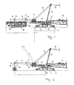
- Fig. 1:
- eine schematische Seitenansicht eines Raupenkrans mit drehbarem Oberwagen, an dem ein noch am Boden liegender Ausleger angelenkt ist, den es aufzurichten gilt, wobei an der Rückseite der Drehbühne ein Aufrichtehilfsrahmen mit daran angehängtem mobilen Hilfskran als Aufrichtehilfsballast befestigt ist, und
- Fig. 2:
- eine schematische Seitenansicht des Krans aus Fig. 1, wobei an dem Aufrichtehilfsrahmen anstelle des Hilfskrans ein üblicher Plattenballast als Aufrichtehilfsballast angehängt ist.
Claims (10)
- Kran mit einem um eine aufrechte Achse (3) drehbaren Oberwagen (4), einem am Oberwagen (4) um eine horizontale Achse (6) wippbar angelenkten Ausleger (5), einer Wippvorrichtung (8, 9, 10) zum Auf- und Abwippen des Auslegers (5) sowie einem dem Moment des Auslegers (5) entgegenwirkenden Betriebsballast (7), dadurch gekennzeichnet, dass ein Aufrichtehilfsrahmen (11) vorgesehen ist, der an dem Oberwagen (4) und/oder dem Betriebsballast (7) nach hinten auskragend befestigbar und mit einem Aufrichtehilfsballast (16) für das Aufrichten des Auslegers (5) verbindbar ist.
- Kran nach dem vorhergehenden Anspruch, wobei der Aufrichtehilfsrahmen (11) Anhängemittel (14) zum Anhängen eines mobilen Hilfskrans als Aufrichtehilfsballast (16) aufweist.
- Kran nach einem der vorhergehenden Ansprüche, wobei die Anhängemittel (2) in Längsrichtung des Aufrichtehilfsrahmens (11) voneinander beabstandete Befestigungselemente (14) aufweisen, deren Abstand voneinander einstellbar ist.
- Kran nach einem der vorhergehenden Ansprüche, wobei die Befestigungselemente (14) von Querträgern (12) getragen werden, von denen zumindest einer in Längsrichtung des Aufrichtehilfsrahmens (11) lageveränderbar, vorzugsweise verschieblich angeordnet ist.
- Kran nach einem der vorhergehenden Ansprüche, wobei die Anhängemittel (14) des Aufrichtehilfsrahmens (11) eine Höheneinstellvorrichtung (13), vorzugsweise einem jeden Befestigungselement (14) zugeordnete Gewindespindeln (13), aufweisen.
- Kran nach einem der vorhergehenden Ansprüche, wobei der Aufrichtehilfsrahmen (11) für den Kranbetrieb aus seiner nach hinten auskragenden Aufrichtestellung in eine Kranbetriebsstellung bringbar ist, in der der Aufrichtehilfsrahmen (11) vorzugsweise im wesentlichen innerhalb eines vom Oberwagen (4) definierten Schwenkbereichs liegt.
- Kran nach einem der vorhergehenden Ansprüche, wobei der Aufrichtehilfsrahmen (11) schwenkbar, vorzugsweise um eine im wesentlichen horizontale Achse, am Oberwagen (4) und/oder Betriebsballast (7) angelenkt und durch eine Schwenkvorrichtung (17), vorzugsweise zumindest einem hydraulischen Kraftheber, zwischen seiner nach hinten auskragenden Aufrichtestellung und einer vorzugsweise nach oben geschwenkten Betriebsstellung verschwenkbar ist.
- Kran nach einem der vorhergehenden Ansprüche, wobei der Aufrichtehilfsrahmen (11) mit lösbaren Befestigungsmitteln lösbar befestigt und demontierbar, insbesondere mittels Befestigungsbolzen am Oberwagen (4) verbolzt ist.
- Kran nach einem der vorhergehenden Ansprüche, wobei der Aufrichtehilfsrahmen (11) frei von Abspannungen am Oberwagen (4) befestigt ist.
- Kran nach einem der vorhergehenden Ansprüche, wobei der Aufrichtehilfsrahmen (11) eine über den Betriebsballast (7) nach hinten auskragende Kraglänge besitzt, die zumindest dem Abstand des Betriebsballastschwerpunkts von der Oberwagendrehachse (3) entspricht.
Applications Claiming Priority (2)
| Application Number | Priority Date | Filing Date | Title |
|---|---|---|---|
| DE20314503U | 2003-09-18 | ||
| DE20314503U DE20314503U1 (de) | 2003-09-18 | 2003-09-18 | Kran |
Publications (3)
| Publication Number | Publication Date |
|---|---|
| EP1516849A2 true EP1516849A2 (de) | 2005-03-23 |
| EP1516849A3 EP1516849A3 (de) | 2006-03-15 |
| EP1516849B1 EP1516849B1 (de) | 2007-05-16 |
Family
ID=34112182
Family Applications (1)
| Application Number | Title | Priority Date | Filing Date |
|---|---|---|---|
| EP04020892A Expired - Lifetime EP1516849B1 (de) | 2003-09-18 | 2004-09-02 | Kran |
Country Status (3)
| Country | Link |
|---|---|
| US (1) | US7213716B2 (de) |
| EP (1) | EP1516849B1 (de) |
| DE (2) | DE20314503U1 (de) |
Families Citing this family (12)
| Publication number | Priority date | Publication date | Assignee | Title |
|---|---|---|---|---|
| US7967158B2 (en) | 2006-10-27 | 2011-06-28 | Manitowoc Crane Companies, Llc | Mobile lift crane with variable position counterweight |
| US8684197B2 (en) * | 2009-05-01 | 2014-04-01 | Manitowoc Crane Companies, Llc | Crane with boom raising assist structure |
| US9278834B2 (en) | 2009-08-06 | 2016-03-08 | Manitowoc Crane Group, LLC | Lift crane with moveable counterweight |
| DE102011105960A1 (de) | 2011-06-29 | 2013-01-03 | Liebherr-Werk Ehingen Gmbh | Verfahren zum Betrieb eines Krans und Kran |
| CN102849624B (zh) | 2011-06-29 | 2016-12-21 | 利勃海尔爱茵根有限公司 | 操作起重机的方法和起重机 |
| DE102012002040B4 (de) | 2012-02-02 | 2022-07-07 | Liebherr-Werk Ehingen Gmbh | Verfahren zum Betrieb eines Krans und Kran |
| DE102011119655A1 (de) | 2011-11-29 | 2013-05-29 | Liebherr-Werk Ehingen Gmbh | Kran |
| US10183848B2 (en) | 2014-01-27 | 2019-01-22 | Manitowoc Crane Companies, Llc | Height adjustment mechanism for an auxiliary member on a crane |
| CN110255402B (zh) | 2014-01-27 | 2022-02-18 | 马尼托瓦克起重机有限责任公司 | 带有改进的可动配重的吊升起重机 |
| DE102014012661B4 (de) | 2014-08-22 | 2019-11-14 | Liebherr-Werk Ehingen Gmbh | Verfahren zum Betrieb eines Krans und Kran |
| DE102015006117A1 (de) | 2015-05-11 | 2016-11-17 | Liebherr-Werk Ehingen Gmbh | Verfahren zum Betrieb eines Krans und Kran |
| JP6658205B2 (ja) * | 2016-03-29 | 2020-03-04 | コベルコ建機株式会社 | クレーン |
Family Cites Families (17)
| Publication number | Priority date | Publication date | Assignee | Title |
|---|---|---|---|---|
| US2068397A (en) * | 1935-06-01 | 1937-01-19 | Chapman Paul | Crane construction |
| DE1209455B (de) | 1962-02-03 | 1966-01-20 | Carl Kaelble G M B H Motoren U | Befestigung von Bodenplatten fuer Kettenglieder von Gleisketten |
| DE1809988A1 (de) * | 1968-11-20 | 1970-06-04 | Krupp Gmbh | Fahrbarer Kran,insbesondere Autokran |
| US3726416A (en) * | 1970-12-15 | 1973-04-10 | Kidde & Co Walter | Extendable counterweight for cranes and method of manipulating |
| FR2257742B1 (de) * | 1974-01-16 | 1976-06-25 | Poclain Sa | |
| US3955684A (en) * | 1975-02-06 | 1976-05-11 | Harnischfeger Corporation | Rotary crane structure with a selective drive on power unit |
| US4108317A (en) * | 1976-05-03 | 1978-08-22 | Fiat-Allis Macchine Movimento Terra S.P.A. | Continuous laying of pipes of large diameter |
| US4195740A (en) * | 1977-04-27 | 1980-04-01 | The Manitowoc Company, Inc. | Lift crane support system |
| AU531998B2 (en) * | 1978-09-05 | 1983-09-15 | Coles Cranes Ltd. | Counterweight removal system |
| US4729486A (en) * | 1986-04-07 | 1988-03-08 | The Manitowoc Company, Inc. | Lift enhancing beam attachment with movable counterweights |
| SU1463705A2 (ru) * | 1986-06-20 | 1989-03-07 | Всесоюзный конструкторско-технологический институт по механизации монтажных и специальных строительных работ | Стреловой грузоподъемный кран |
| US5586667A (en) * | 1995-12-14 | 1996-12-24 | Landry Camile J | Mobile crane with main and auxiliary counterweight assemblies |
| US6065620A (en) * | 1998-03-27 | 2000-05-23 | Trans World Crane, Incorporated | Movable sheave assembly for a crane |
| DE19857779A1 (de) * | 1998-12-04 | 2000-06-15 | Mannesmann Ag | Kran, insbesondere Fahrzeugkran |
| DE29823183U1 (de) | 1998-12-29 | 2000-05-11 | IBG Immobilien- und Bauelemente GmbH, 63579 Freigericht | Holzkohlegrill |
| JP2001164787A (ja) * | 1999-12-10 | 2001-06-19 | Ishikawajima Harima Heavy Ind Co Ltd | タンク屋根揚げ時の屋根除荷方法 |
| ATE361259T1 (de) * | 2001-11-05 | 2007-05-15 | Kobelco Cranes Co Ltd | Baumaschine und verfahren der selbstmontage und - demontage |
-
2003
- 2003-09-18 DE DE20314503U patent/DE20314503U1/de not_active Expired - Lifetime
-
2004
- 2004-09-02 DE DE502004003823T patent/DE502004003823D1/de not_active Expired - Lifetime
- 2004-09-02 EP EP04020892A patent/EP1516849B1/de not_active Expired - Lifetime
- 2004-09-20 US US10/945,454 patent/US7213716B2/en not_active Expired - Lifetime
Also Published As
| Publication number | Publication date |
|---|---|
| US20050061761A1 (en) | 2005-03-24 |
| EP1516849A3 (de) | 2006-03-15 |
| DE20314503U1 (de) | 2005-01-27 |
| EP1516849B1 (de) | 2007-05-16 |
| US7213716B2 (en) | 2007-05-08 |
| DE502004003823D1 (de) | 2007-06-28 |
Similar Documents
| Publication | Publication Date | Title |
|---|---|---|
| WO2006058751A2 (de) | Fahrzeugkran | |
| DE3824732A1 (de) | Kran, insbesondere grosskran | |
| DE69714690T2 (de) | Verfahren und Vorrichtung zum Montieren der Seilzüge der Ausleger von Turmkränen | |
| EP2067737B1 (de) | Seitliche Abspannung für einen Gitterausleger eines Kranes | |
| EP1516849B1 (de) | Kran | |
| AT523474B1 (de) | Auslegersystem für einen Fahrzeugkran mit Abspannvorrichtung sowie Verfahren zum Aufrüsten und Abrüsten einer Abspannvorrichtung eines Fahrzeugkrans | |
| DE3934783A1 (de) | Kran und verfahren fuer dessen verwendung | |
| DE60113546T2 (de) | Kran mit aus gliedern bestehendem kranarm | |
| DE2222526A1 (de) | Beweglicher Turmkran | |
| DE19814636A1 (de) | Ringliftkran | |
| DE69222916T2 (de) | System zum Ausrichten eines oberen Rahmens auf einen unteren Rahmen eines Krans | |
| DE102021111922B3 (de) | Abspannsystem und -verfahren für einen Mobilkran-Teleskopausleger | |
| EP0384112A2 (de) | Turmdrehkran, vorzugsweise oben drehender Turmdrehkran | |
| DE1278708B (de) | Transportabler Turmdrehkran | |
| CH665237A5 (en) | Bulldozer blade mounting - has double acting rams with linkage on horizontal vehicle axis to blade end hinge | |
| DE60316358T2 (de) | Mobilkran | |
| DE3042287A1 (de) | Ausleger eines teleskopkranes | |
| DE202005005627U1 (de) | Kran sowie Abspannvorrichtung hierfür | |
| DE2450003C2 (de) | Fahrzeugkran mit Kabine mit verschiedenen Stellungen | |
| DE102014001870B4 (de) | Mobilkran | |
| DE872259C (de) | Hubvorrichtung | |
| EP1524235B1 (de) | Kran sowie Verfahren zur Aufrichtung seines Auslegers | |
| DE102009030741B4 (de) | Vorrichtung und Verfahren zur Montage und/oder Demontage eines Kranauslegers und Kran mit einer derartigen Vorrichtung | |
| DE102022128653B4 (de) | Fahrbarer Kran mit Gittermastausleger, Gittermastausleger sowie Verfahren zur Montage eines solchen | |
| DE202005003207U1 (de) | Fahrzeugkran |
Legal Events
| Date | Code | Title | Description |
|---|---|---|---|
| PUAI | Public reference made under article 153(3) epc to a published international application that has entered the european phase |
Free format text: ORIGINAL CODE: 0009012 |
|
| AK | Designated contracting states |
Kind code of ref document: A2 Designated state(s): AT BE BG CH CY CZ DE DK EE ES FI FR GB GR HU IE IT LI LU MC NL PL PT RO SE SI SK TR |
|
| AX | Request for extension of the european patent |
Extension state: AL HR LT LV MK |
|
| PUAL | Search report despatched |
Free format text: ORIGINAL CODE: 0009013 |
|
| AK | Designated contracting states |
Kind code of ref document: A3 Designated state(s): AT BE BG CH CY CZ DE DK EE ES FI FR GB GR HU IE IT LI LU MC NL PL PT RO SE SI SK TR |
|
| AX | Request for extension of the european patent |
Extension state: AL HR LT LV MK |
|
| RIC1 | Information provided on ipc code assigned before grant |
Ipc: B66C 23/74 20060101AFI20060125BHEP |
|
| 17P | Request for examination filed |
Effective date: 20060323 |
|
| AKX | Designation fees paid |
Designated state(s): DE FR GB |
|
| GRAP | Despatch of communication of intention to grant a patent |
Free format text: ORIGINAL CODE: EPIDOSNIGR1 |
|
| GRAS | Grant fee paid |
Free format text: ORIGINAL CODE: EPIDOSNIGR3 |
|
| GRAA | (expected) grant |
Free format text: ORIGINAL CODE: 0009210 |
|
| AK | Designated contracting states |
Kind code of ref document: B1 Designated state(s): DE FR GB |
|
| REG | Reference to a national code |
Ref country code: GB Ref legal event code: FG4D Free format text: NOT ENGLISH |
|
| REF | Corresponds to: |
Ref document number: 502004003823 Country of ref document: DE Date of ref document: 20070628 Kind code of ref document: P |
|
| GBT | Gb: translation of ep patent filed (gb section 77(6)(a)/1977) |
Effective date: 20070705 |
|
| ET | Fr: translation filed | ||
| PLBE | No opposition filed within time limit |
Free format text: ORIGINAL CODE: 0009261 |
|
| STAA | Information on the status of an ep patent application or granted ep patent |
Free format text: STATUS: NO OPPOSITION FILED WITHIN TIME LIMIT |
|
| 26N | No opposition filed |
Effective date: 20080219 |
|
| PGFP | Annual fee paid to national office [announced via postgrant information from national office to epo] |
Ref country code: GB Payment date: 20130925 Year of fee payment: 10 |
|
| GBPC | Gb: european patent ceased through non-payment of renewal fee |
Effective date: 20140902 |
|
| PG25 | Lapsed in a contracting state [announced via postgrant information from national office to epo] |
Ref country code: GB Free format text: LAPSE BECAUSE OF NON-PAYMENT OF DUE FEES Effective date: 20140902 |
|
| REG | Reference to a national code |
Ref country code: FR Ref legal event code: PLFP Year of fee payment: 13 |
|
| PGFP | Annual fee paid to national office [announced via postgrant information from national office to epo] |
Ref country code: FR Payment date: 20160923 Year of fee payment: 13 |
|
| REG | Reference to a national code |
Ref country code: FR Ref legal event code: ST Effective date: 20180531 |
|
| PG25 | Lapsed in a contracting state [announced via postgrant information from national office to epo] |
Ref country code: FR Free format text: LAPSE BECAUSE OF NON-PAYMENT OF DUE FEES Effective date: 20171002 |
|
| PGFP | Annual fee paid to national office [announced via postgrant information from national office to epo] |
Ref country code: DE Payment date: 20181001 Year of fee payment: 15 |
|
| REG | Reference to a national code |
Ref country code: DE Ref legal event code: R119 Ref document number: 502004003823 Country of ref document: DE |
|
| PG25 | Lapsed in a contracting state [announced via postgrant information from national office to epo] |
Ref country code: DE Free format text: LAPSE BECAUSE OF NON-PAYMENT OF DUE FEES Effective date: 20200401 |