EP1516849A2 - Crane - Google Patents
Crane Download PDFInfo
- Publication number
- EP1516849A2 EP1516849A2 EP04020892A EP04020892A EP1516849A2 EP 1516849 A2 EP1516849 A2 EP 1516849A2 EP 04020892 A EP04020892 A EP 04020892A EP 04020892 A EP04020892 A EP 04020892A EP 1516849 A2 EP1516849 A2 EP 1516849A2
- Authority
- EP
- European Patent Office
- Prior art keywords
- crane
- auxiliary frame
- erecting
- ballast
- crane according
- Prior art date
- Legal status (The legal status is an assumption and is not a legal conclusion. Google has not performed a legal analysis and makes no representation as to the accuracy of the status listed.)
- Granted
Links
Images
Classifications
-
- B—PERFORMING OPERATIONS; TRANSPORTING
- B66—HOISTING; LIFTING; HAULING
- B66C—CRANES; LOAD-ENGAGING ELEMENTS OR DEVICES FOR CRANES, CAPSTANS, WINCHES, OR TACKLES
- B66C23/00—Cranes comprising essentially a beam, boom, or triangular structure acting as a cantilever and mounted for translatory of swinging movements in vertical or horizontal planes or a combination of such movements, e.g. jib-cranes, derricks, tower cranes
- B66C23/62—Constructional features or details
- B66C23/72—Counterweights or supports for balancing lifting couples
- B66C23/74—Counterweights or supports for balancing lifting couples separate from jib
Definitions
- the present invention relates to a crane with an about an upright axis rotatable superstructure, one on the superstructure about a horizontal axis tiltable articulated boom, a luffing device for rocking up and down the boom, and a counteracting the moment of the boom operating ballast.
- the present invention is therefore based on the object, an improved Crane of the type mentioned, the disadvantages of the prior art Avoiding technology and the latter develops in an advantageous manner.
- the erection of very long boom combinations be achieved without to provide redundant ballast for the operation.
- the crane is thus characterized in that a erecting auxiliary frame is provided, according to the superstructure and / or the operating ballast cantilevered at the rear and with a righting ballast for erecting the boom is connectable.
- the Aufrichteangesrahmen can thereby on the Rear of the superstructure or the attached operating ballast attached be that from the opposite side of the boom from the boom protrudes to the rear and has an extended lever arm, where the Rearing auxiliary ballast can be attached.
- the righting help ballast becomes special attached for erecting the boom on the erecting auxiliary frame and for the Crane operation removed. Due to the Aufrichteosrahmen he has a very large Lever arm, the Nachvornekippen the crane when erecting even long boom prevented.
- a preferably mobile auxiliary crane to be attached which is used to assemble the crane place.
- the erecting auxiliary frame has for this purpose suitable attachment means to which the auxiliary crane can be attached as Aufrichteangesballast.
- the usage the mobile auxiliary crane, which actually serves to build the crane, as additional ballast has the advantage that additional low loaders can be saved with which otherwise additional revolving ballast transported to the site would have to be.
- the erecting auxiliary frame for crane operation is off its rearwardly projecting position in another crane operating position Can be brought in the Aufrichteangesrahmen substantially within that of the superstructure or the operating ballast fixed thereto pivoting range lies.
- the rear-projecting erection frame would be disturbing, so that it advantageously from its rearwardly projecting upright position can be removed.
- the erection frame can be pivoted on the uppercarriage and / or the Operating ballast articulated and by a pivoting device between the post swung rear projecting upright position and a crane operating position become.
- the pivot axis about which the erection frame can be pivoted advantageously extends substantially horizontally in the region of Upper carriage, so that the erection frame by the pivoting device after can be swung up in the said crane operating position.
- the Pivoting device can basically be designed differently.
- a preferred embodiment of the invention is at least one hydraulic power lift provided for upward pivoting of Aufrichteevers.
- the erection frame can be detached with releasable attachment means be attached and dismounted. This allows the erection frame after the Erecting the boom are completely disassembled, so that in crane operation no disturbing effect of Aufrichterahmens is given.
- the previously described embodiment after which the erection frame in an upward tilted crane operating position can be brought, the advantage that the Aufrichtahmen can be used as additional ballast use.
- the trailing means of the erecting auxiliary frame to which the erecting auxiliary ballast can be hung in the invention two in the longitudinal direction the Aufrichteanges spaced apart fasteners have, whose distance is adjustable from each other.
- the adjustable distance of the Suspension points allow various sized mobile auxiliary cranes as Aufrichteangesballast to use.
- the auxiliary cranes at their Bodenabstützungen be hung up. In so far as their distance vary depending on the mobile crane can, it allows the variable-spacing formation of the fasteners on the erecting auxiliary frame, differently shaped auxiliary cranes on the erecting auxiliary frame attach.
- the fasteners even at a fixed, unchanged distance to the erecting auxiliary frame be arranged, if it is sufficient, with only a certain additional ballast or mobile crane.
- the fasteners of cross members be formed, of which at least one in the longitudinal direction of the erecting auxiliary frame changeable, preferably arranged displaceably on the erecting auxiliary frame is.
- the cross beams cantilever transversely to the longitudinal direction of Aufrichteangesrahmens beyond this. They can hook at their ends or other suitable fasteners have, where support cables or the like for attaching the Rearing aid ballasts can be attached.
- the height adjustment device can be designed differently.
- the height adjustment device is designed such that each breakpoint the towing means is separately height adjustable.
- the invention associated with each fastener each have a threaded spindle be, with the help of which the attachment point is height adjustable.
- the erection frame may vary in length.
- the over the operating ballast Rearwardly projecting cantilever of the erection frame is preferably adapted to the length of the erectile boom that a suitable Aufrichteangesballast sufficient.
- the Rigid auxiliary frame a projecting beyond the operating ballast to the rear Have Kragander, at least the distance of the operating ballast center of gravity from the superstructure axis of rotation corresponds.
- the crane shown in the figures has an undercarriage 1 with a chassis 2, which is designed in the illustrated embodiment as a crawler chassis and comprises two right and left arranged caterpillar tracks.
- a chassis 2 which is designed in the illustrated embodiment as a crawler chassis and comprises two right and left arranged caterpillar tracks.
- On the undercarriage 1 is about an upright axis of rotation 3, a revolving stage or a superstructure 4 rotatable stored.
- the upper carriage 4 carries a boom 5, which is about a horizontal rocking axis 6 is articulated to the superstructure 4 and in a conventional manner a hoist rope drain over its top.
- the boom 5 can be about a guy 8 to the rocker axis 6 up and tipped off and erected from the position shown in the drawings.
- the bracing 8 is guided over a support arm 9 to the bracing. 8 to give a cheaper lever arm.
- the support arm 9 is one to the rocking axis 6 parallel axis swiveling.
- the bracing is known per se Way over multiple reeving adjustment cables 10 in the area of the operating ballast 7 led to the superstructure.
- the erecting auxiliary frame 11 preferably consists of two parallel longitudinal members, which several transverse profiles are welded together. It is understood that the erecting auxiliary frame 11 but also be designed as truss or otherwise could.
- the erecting auxiliary frame 11 extends in a flat uprising of the crane essentially horizontally to the rear, substantially at the level of the upper side
- the erecting auxiliary frame 11 is arranged so high, that a mobile auxiliary crane, which is used for the construction of the crane, under he is mobile.
- the cross member 12 are advantageously so from each other spaced, that their distance from the distance of ground supports of the auxiliary crane equivalent.
- the side out of the auxiliary crane extended floor supports attached by means of steel ropes 15 to the cross members 12, so that the auxiliary crane forms a rearing aid ballast 16.
- the erecting auxiliary frame 11 can in principle be rigidly bolted to the uppercarriage 4 so that he takes the drawing position drawn in the figures.
- the erecting auxiliary frame is then aborted and removed.
- the operating ballast 7 alone is sufficient for the operation of the crane in particular then, if this is operated only with a steeply erected boom.
- the erecting auxiliary frame 11 on the Upper carriage 4 also be pivotally mounted, and advantageously by one to Wippachse 6 parallel axis.
- the erecting auxiliary frame 11 can be a Swivel drive 17 assigned for example in the form of a hydraulic power lift be, with the help of which the erecting auxiliary frame 11 from the substantially horizontally rearwardly projecting upright position into an operating position can be pivoted upward, which is indicated by dashed lines in Figure 2.
- the upwardly pivoted operating position of Aufrichteangesrahmen 11 is at least so far pivoted that he over obstacles standing on the ground away swings.
- the erecting auxiliary frame 11 can be as far behind be pivoted above, that he is within the from the trailing edge of the superstructure 4 defined pivoting circle comes to rest. Compared to Figure 2 would be to swing the erecting auxiliary frame a little further upwards. Not to collide with the Verstellverseilung 10, the Aufrichteangesrahmen in the area its articulation possess a U-shaped profile, so that the stranding between can pass through the two thighs.
Abstract
Description
Die vorliegende Erfindung betrifft einen Kran mit einem um eine aufrechte Achse drehbaren Oberwagen, einem am Oberwagen um eine horizontale Achse wippbar angelenkten Ausleger, einer Wippvorrichtung zum Auf- und Abwippen des Auslegers, sowie einem dem Moment des Auslegers entgegenwirkenden Betriebsballast.The present invention relates to a crane with an about an upright axis rotatable superstructure, one on the superstructure about a horizontal axis tiltable articulated boom, a luffing device for rocking up and down the boom, and a counteracting the moment of the boom operating ballast.
Beim Aufrichten von sehr langen Auslegern besteht das Problem, dass die am Boden liegenden Ausleger einen sehr großen Hebelarm besitzen und dementsprechend ein großes Moment induzieren. Um dieses auszugleichen, muss ein entsprechend schwerer Gegenballast am Kran angebracht werden, damit der Ausleger überhaupt aufgerichtet werden kann. Andererseits ist im Kranbetrieb oftmals ein so großer Ballast nicht erforderlich, da bei bestimmten Anwendungen der Kranausleger stets in relativ steiler Wippstellung gefahren wird. Um den Kranausleger dennoch mit einem verhältnismäßig kleineren Betriebsballast aufrichten zu können, wurde bereits vorgeschlagen, eine vor dem Oberwagen des Krans angeordnete Zusatzabstützung vorzusehen, die beim Aufrichten des Auslegers ein Nachvomekippen des Krans verhindert. Solche Zusatzabstützungen erfordern jedoch regelmäßig das Vorsehen entsprechender Fundamente. When erecting very long outriggers, the problem is that the ground lying boom have a very large lever arm and accordingly induce a big moment. To make up for this, one must be appropriate heavy counter ballast be attached to the crane so that the boom can be erected at all. On the other hand, it is often the case in crane operation Large ballast is not required because in certain applications the crane boom always driven in relatively steep rocking position. Nevertheless, to the crane boom to be able to raise with a relatively smaller operating ballast, has already been proposed, one arranged in front of the superstructure of the crane Provide additional support that tilt a Nachvome when erecting the boom of the crane prevented. However, such additional supports require regular the provision of appropriate foundations.
Der vorliegenden Erfindung liegt daher die Aufgabe zugrunde, einen verbesserten Kran der eingangs genannten Art zu schaffen, der Nachteile des Standes der Technik vermeidet und letzteren in vorteilhafter Weise weiterbildet. Vorzugsweise soll das Aufrichten auch sehr langer Auslegerkombinationen erreicht werden, ohne für den Betrieb überflüssigen Ballast vorsehen zu müssen.The present invention is therefore based on the object, an improved Crane of the type mentioned, the disadvantages of the prior art Avoiding technology and the latter develops in an advantageous manner. Preferably should the erection of very long boom combinations be achieved without to provide redundant ballast for the operation.
Erfindungsgemäß wird diese Aufgabe durch einen Kran gemäß Anspruch 1 gelöst. Bevorzugte Ausgestaltungen der Erfindung sind Gegenstand der abhängigen Ansprüche.According to the invention, this object is achieved by a crane according to claim 1. Preferred embodiments of the invention are the subject of the dependent claims.
Erfindungsgemäß zeichnet sich der Kran also dadurch aus, dass ein Aufrichtehilfsrahmen vorgesehen ist, der an dem Oberwagen und/oder dem Betriebsballast nach hinten auskragend befestigbar und mit einem Aufrichtehilfsballast für das Aufrichten des Auslegers verbindbar ist. Der Aufrichtehilfsrahmen kann dabei derart an der Rückseite des Oberwagens bzw. dem daran befestigten Betriebsballast angebracht werden, dass er von der dem Ausleger gegenüberliegenden Rückseite des Oberwagens nach hinten auskragt und einen verlängerten Hebelarm besitzt, an dem der Aufrichtehilfsballast befestigt werden kann. Der Aufrichtehilfsballast wird speziell zum Aufrichten des Auslegers an dem Aufrichtehilfsrahmen befestigt und für den Kranbetrieb entfernt. Durch den Aufrichtehilfsrahmen besitzt er einen sehr großen Hebelarm, der ein Nachvornekippen des Krans beim Aufrichten auch langer Ausleger verhindert.According to the invention, the crane is thus characterized in that a erecting auxiliary frame is provided, according to the superstructure and / or the operating ballast cantilevered at the rear and with a righting ballast for erecting the boom is connectable. The Aufrichtehilfsrahmen can thereby on the Rear of the superstructure or the attached operating ballast attached be that from the opposite side of the boom from the boom protrudes to the rear and has an extended lever arm, where the Rearing auxiliary ballast can be attached. The righting help ballast becomes special attached for erecting the boom on the erecting auxiliary frame and for the Crane operation removed. Due to the Aufrichtehilfsrahmen he has a very large Lever arm, the Nachvornekippen the crane when erecting even long boom prevented.
In Weiterbildung der Erfindung kann an den Aufrichtehilfsrahmen ein vorzugsweise mobiler Hilfskran angehängt werden, der zum Zusammenbau des Krans Verwendung findet. Der Aufrichtehilfsrahmen besitzt hierzu geeignete Anhängemittel, an die der Hilfskran als Aufrichtehilfsballast angehängt werden kann. Die Verwendung des mobilen Hilfskrans, der eigentlich dem Aufbauen des Krans dient, als Zusatzballast besitzt den Vorteil, dass zusätzliche Tieflader eingespart werden können, mit denen ansonsten zusätzlicher Drehbühnenballast an die Baustelle transportiert werden müsste. In a further development of the invention can be on the erecting auxiliary frame a preferably mobile auxiliary crane to be attached, which is used to assemble the crane place. The erecting auxiliary frame has for this purpose suitable attachment means to which the auxiliary crane can be attached as Aufrichtehilfsballast. The usage the mobile auxiliary crane, which actually serves to build the crane, as additional ballast has the advantage that additional low loaders can be saved with which otherwise additional revolving ballast transported to the site would have to be.
Es versteht sich jedoch, dass ggf. auch anderweitig vorhandener Zusatzballast als Aufrichtehilfsballast an den Aufrichtehilfsrahmen gehängt werden kann.It is understood, however, that possibly also otherwise available additional ballast than Rearing auxiliary ballast can be hung on the erecting auxiliary frame.
In Weiterbildung der Erfindung ist der Aufrichtehilfsrahmen für den Kranbetrieb aus seiner nach hinten auskragenden Stellung in eine weitere Kranbetriebsstellung bringbar, in der der Aufrichtehilfsrahmen im wesentlichen innerhalb des vom Oberwagen bzw. dem daran befestigten Betriebsballast definierten Schwenkbereichs liegt. Für den Kranbetrieb wäre der nach hinten auskragende Aufrichterahmen störend, so dass er vorteilhafterweise aus seiner nach hinten auskragenden Aufrichtestellung entfernt werden kann.In development of the invention, the erecting auxiliary frame for crane operation is off its rearwardly projecting position in another crane operating position Can be brought in the Aufrichtehilfsrahmen substantially within that of the superstructure or the operating ballast fixed thereto pivoting range lies. For crane operation, the rear-projecting erection frame would be disturbing, so that it advantageously from its rearwardly projecting upright position can be removed.
Insbesondere kann der Aufrichterahmen schwenkbar am Oberwagen und/oder dem Betriebsballast angelenkt und durch eine Schwenkvorrichtung zwischen der nach hinten auskragenden Aufrichtestellung und einer Kranbetriebsstellung verschwenkt werden. Die Schwenkachse, um die der Aufrichterahmen geschwenkt werden kann, erstreckt sich vorteilhafterweise im wesentlichen horizontal im Bereich des Oberwagens, so dass der Aufrichterahmen durch die Schwenkvorrichtung nach oben in die genannte Kranbetriebsstellung geschwenkt werden kann. Die Schwenkvorrichtung kann grundsätzlich verschieden ausgebildet sein. Nach einer bevorzugten Ausführung der Erfindung ist zumindest ein hydraulischer Kraftheber zum Nachobenschwenken des Aufrichtehilfsrahmens vorgesehen.In particular, the erection frame can be pivoted on the uppercarriage and / or the Operating ballast articulated and by a pivoting device between the post swung rear projecting upright position and a crane operating position become. The pivot axis about which the erection frame can be pivoted advantageously extends substantially horizontally in the region of Upper carriage, so that the erection frame by the pivoting device after can be swung up in the said crane operating position. The Pivoting device can basically be designed differently. After a preferred embodiment of the invention is at least one hydraulic power lift provided for upward pivoting of Aufrichtehilfsrahmens.
Vorteilhafterweise kann der Aufrichterahmen mit lösbaren Befestigungsmitteln lösbar befestigt und demontierbar sein. Hierdurch kann der Aufrichterahmen nach dem Aufrichten des Auslegers gänzlich demontiert werden, so dass im Kranbetrieb keinerlei störende Wirkung des Aufrichterahmens gegeben ist. Andererseits besitzt die zuvor beschriebene Ausführung, wonach der Aufrichterahmen in eine nach oben geschwenkte Kranbetriebsstellung gebracht werden kann, den Vorteil, dass der Aufrichterahmen als zusätzlicher Ballast Verwendung finden kann. Advantageously, the erection frame can be detached with releasable attachment means be attached and dismounted. This allows the erection frame after the Erecting the boom are completely disassembled, so that in crane operation no disturbing effect of Aufrichterahmens is given. On the other hand, the previously described embodiment, after which the erection frame in an upward tilted crane operating position can be brought, the advantage that the Aufrichtahmen can be used as additional ballast use.
Die Anhängemittel des Aufrichtehilfsrahmens, an denen der Aufrichtehilfsballast aufgehängt werden kann, können in Weiterbildung der Erfindung zwei in Längsrichtung des Aufrichtehilfsrahmens voneinander beabstandete Befestigungselemente aufweisen, deren Abstand voneinander einstellbar ist. Der einstellbare Abstand der Aufhängepunkte erlaubt es, verschieden große mobile Hilfskrane als Aufrichtehilfsballast zu verwenden. Insbesondere können die Hilfskrane an ihren Bodenabstützungen aufgehängt werden. Insofern als deren Abstand je nach Mobilkran variieren kann, erlaubt es die abstandsveränderliche Ausbildung der Befestigungselemente an dem Aufrichtehilfsrahmen, verschieden ausgebildete Hilfskräne an dem Aufrichtehilfsrahmen anzuhängen. Gegebenenfalls können die Befestigungselemente jedoch auch in fest vorgegebenem, unverändertem Abstand an dem Aufrichtehilfsrahmen angeordnet sein, wenn es ausreichend ist, mit nur einem bestimmten Zusatzballast bzw. Mobilhilfskran zu arbeiten.The trailing means of the erecting auxiliary frame to which the erecting auxiliary ballast can be hung in the invention, two in the longitudinal direction the Aufrichtehilfsrahmens spaced apart fasteners have, whose distance is adjustable from each other. The adjustable distance of the Suspension points allow various sized mobile auxiliary cranes as Aufrichtehilfsballast to use. In particular, the auxiliary cranes at their Bodenabstützungen be hung up. In so far as their distance vary depending on the mobile crane can, it allows the variable-spacing formation of the fasteners on the erecting auxiliary frame, differently shaped auxiliary cranes on the erecting auxiliary frame attach. Optionally, however, the fasteners even at a fixed, unchanged distance to the erecting auxiliary frame be arranged, if it is sufficient, with only a certain additional ballast or mobile crane.
In Weiterbildung der Erfindung können die Befestigungselemente von Querträgern gebildet sein, von denen zumindest einer in Längsrichtung des Aufrichtehilfsrahmens veränderbar, vorzugsweise verschieblich an dem Aufrichtehilfsrahmen angeordnet ist. Die Querträger kragen quer zur Längsrichtung des Aufrichtehilfsrahmens über diesen hinaus. Sie können an ihren Enden Haken oder andere geeignete Befestigungsmittel besitzen, an denen Tragseile oder dergleichen zum Anhängen des Aufrichtehilfsballasts befestigt werden können.In a further development of the invention, the fasteners of cross members be formed, of which at least one in the longitudinal direction of the erecting auxiliary frame changeable, preferably arranged displaceably on the erecting auxiliary frame is. The cross beams cantilever transversely to the longitudinal direction of Aufrichtehilfsrahmens beyond this. They can hook at their ends or other suitable fasteners have, where support cables or the like for attaching the Rearing aid ballasts can be attached.
In Weiterbildung der Erfindung besitzen die Anhängemittel des Aufrichtehilfsrahmens eine Höheneinstellvorrichtung, um Niveauunterschiede zwischen dem Kran und dem daran befestigten Aufrichtehilfsrahmen und dem Aufrichtehilfsballast ausgleichen zu können, z. B. dann, wenn der Boden hinter dem Kran leicht geneigt verläuft. Die Höheneinstellvorrichtung kann verschieden ausgebildet sein. Vorzugsweise ist die Höheneinstellvorrichtung derart ausgebildet, dass jeder Haltepunkt der Anhängemittel separat höheneinstellbar ist. Es können in Weiterbildung der Erfindung jedem Befestigungselement jeweils eine Gewindespindel zugeordnet sein, mit Hilfe derer der Anhängepunkt höheneinstellbar ist. In development of the invention, the trailing means of Aufrichtehilfsrahmens a height adjustment device to level differences between the crane and the attached erecting auxiliary frame and the erecting auxiliary ballast to be able to, for. B. when the ground behind the crane slightly inclined runs. The height adjustment device can be designed differently. Preferably the height adjustment device is designed such that each breakpoint the towing means is separately height adjustable. It can be further education the invention associated with each fastener each have a threaded spindle be, with the help of which the attachment point is height adjustable.
Um den Aufrichterahmen leicht bauen zu können, könnte grundsätzlich eine Abspannung für den Aufrichtehilfsrahmen vorgesehen sein, mit der dieser an der Abspannung des Auslegers angehängt wird. In Weiterbildung der Erfindung kann der Aufrichterahmen jedoch auch frei von Abspannungen am Oberwagen befestigt sein. Hierdurch wird die Montage erleichtert. Abspannseile oder -stangen brauchen nicht montiert zu werden.In order to build the erection frame easily, could basically a bracing be provided for the Aufrichtehilfsrahmen, with this at the bracing of the jib is attached. In a further development of the invention, the However, erection frames also fastened free of bracing on the superstructure be. As a result, the assembly is facilitated. Tie down ropes or rods need not to be mounted.
Der Aufrichterahmen kann in seiner Länge variieren. Die über den Betriebsballast nach hinten hinaus auskragende Kraglänge des Aufrichterahmens wird vorzugsweise so an die Länge des aufzurichtenden Auslegers angepasst, dass ein geeigneter Aufrichtehilfsballast ausreicht. Nach einer Ausführung der Erfindung kann der Aufrichtehilfsrahmen eine über den Betriebsballast nach hinten hinausragende Kraglänge besitzen, die zumindest dem Abstand des Betriebsballastschwerpunkts von der Oberwagendrehachse entspricht.The erection frame may vary in length. The over the operating ballast Rearwardly projecting cantilever of the erection frame is preferably adapted to the length of the erectile boom that a suitable Aufrichtehilfsballast sufficient. According to one embodiment of the invention, the Rigid auxiliary frame a projecting beyond the operating ballast to the rear Have Kraglänge, at least the distance of the operating ballast center of gravity from the superstructure axis of rotation corresponds.
Die Erfindung wird nachfolgend anhand eines bevorzugten Ausführungsbeispiels und zugehöriger Zeichnungen näher erläutert. In den Zeichnungen zeigen:
- Fig. 1:
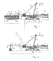
- eine schematische Seitenansicht eines Raupenkrans mit drehbarem Oberwagen, an dem ein noch am Boden liegender Ausleger angelenkt ist, den es aufzurichten gilt, wobei an der Rückseite der Drehbühne ein Aufrichtehilfsrahmen mit daran angehängtem mobilen Hilfskran als Aufrichtehilfsballast befestigt ist, und
- Fig. 2:
- eine schematische Seitenansicht des Krans aus Fig. 1, wobei an dem Aufrichtehilfsrahmen anstelle des Hilfskrans ein üblicher Plattenballast als Aufrichtehilfsballast angehängt ist.
- Fig. 1:
- a schematic side view of a crawler crane with a rotatable superstructure, on which a still lying on the floor boom is erected, where it is attached to the back of the revolving platform Aufrichtehilfsrahmen attached thereto mobile auxiliary crane as Aufrichtehilfsballast, and
- Fig. 2:
- a schematic side view of the crane of Fig. 1, wherein a conventional plate ballast is attached as Aufrichtehilfsballast to the Aufrichtehilfsrahmen instead of the auxiliary crane.
Der in den Figuren gezeigte Kran besitzt einen Unterwagen 1 mit einem Fahrwerk
2, das in der gezeichneten Ausführung als Raupenfahrwerk ausgebildet ist und
zwei rechts und links angeordnete Raupenketten umfasst. Auf dem Unterwagen 1
ist um eine aufrechte Drehachse 3 eine Drehbühne bzw. ein Oberwagen 4 drehbar
gelagert. Der Oberwagen 4 trägt einen Ausleger 5, der um eine horizontale Wippachse
6 an dem Oberwagen 4 angelenkt ist und in an sich üblicher Weise ein Hubseil
über seine Spitze ablaufen lässt.The crane shown in the figures has an undercarriage 1 with a
An dem der Anlenkstelle des Auslegers 5 gegenüberliegenden Rückseite des
Oberwagens 4 trägt dieser einen Betriebsballast 7, der dem vom Ausleger 5 bzw.
einer daran hängenden Last induzierten Kippmoment entgegenwirkt.At the opposite of the pivot point of the
Der Ausleger 5 kann über eine Abspannung 8 um die Wippachse 6 auf- und abgewippt
sowie aus der in den Zeichnungen gezeigten Stellung aufgerichtet werden.
Die Abspannung 8 ist über einen Stützausleger 9 geführt, um der Abspannung 8
einen günstigeren Hebelarm zu geben. Der Stützausleger 9 ist um eine zur Wippachse
6 parallele Achse schwenkbar. Die Abspannung wird in an sich bekannter
Weise über mehrfach eingescherte Verstellseile 10 im Bereich des Betriebsballasts
7 auf den Oberwagen geführt.The
Um das Aufrichten des ggf. sehr langen Auslegers 5 aus der in den Figuren gezeichneten
am Boden abgelegten Stellung bei nur begrenztem Betriebsballast, der
dafür eigentlich zu gering wäre, zu erlauben, ist an der Rückseite des Oberwagens
4 ein Aufrichtehilfsausleger 11 mit Verriegelungsbolzen angebolzt. Der Aufrichtehilfsrahmen
11 besteht vorzugsweise aus zwei parallelen Längsträgern, die durch
mehrere Querprofile miteinander verschweißt sind. Es versteht sich, dass der Aufrichtehilfsrahmen
11 jedoch auch als Fachwerkträger oder anders ausgebildet sein
könnte. Der Aufrichtehilfsrahmen 11 erstreckt sich bei ebenem Aufstand des Krans
im wesentlichen horizontal nach hinten, im wesentlichen in der Höhe der Oberseite
des Oberwagens 4. Auf alle Fälle ist der Aufrichtehilfsrahmen 11 so hoch angeordnet,
dass ein mobiler Hilfskran, der zum Aufbau des Krans Verwendung findet, unter
ihn fahrbar ist.To erect the possibly very
Auf der Oberseite des Aufrichtehilfsrahmens 11 sind Querträger 12 angebracht, die
seitlich über den Aufrichtehilfsrahmen 11 hinauskragen und auf diesem in Längsrichtung
des Aufrichtehilfsrahmens 11 lageveränderbar angeordnet sind. Die Querträger
12 können beispielsweise längsverschieblich auf dem Aufrichtehilfsrahmen
11 gelagert sein und in verschiedenen Stellungen fixiert werden. An den Enden der
Querträger 12 sind vertikal wirksame Gewindespindeln 13 vorgesehen, die Befestigungselemente
beispielsweise in Form von Haken tragen, an denen Stahltrossen
zum Anhängen des Aufrichtehilfsballasts befestigt werden können. Mit Hilfe der
Gewindespindeln 13 kann der Haltepunkt der Befestigungselemente 14 höheneingestellt
werden, um Niveauunterschiede zwischen dem Aufrichtehilfsrahmen 11
und dem Boden darunter ausgleichen zu können.On the top of
Wie Figur 1 zeigt, werden die Querträger 12 vorteilhafterweise derart voneinander
beabstandet, dass ihr Abstand dem Abstand von Bodenabstützungen des Hilfskrans
entspricht. Die seitlich aus dem Hilfskran ausgefahrenen Bodenstützen werden
mittels Stahltrossen 15 an den Querträgern 12 angehängt, so dass der Hilfskran
einen Aufrichtehilfsballast 16 bildet.As Figure 1 shows, the
Es versteht sich, dass anstelle des mobilen Hilfskrans auch ein separater Zuatzballast angehängt werden kann, wie dies Figur 2 zeigt.It is understood that instead of the mobile auxiliary crane and a separate additional ballast can be attached, as shown in Figure 2.
Der Aufrichtehilfsrahmen 11 kann grundsätzlich starr an dem Oberwagen 4 angebolzt
werden, so dass er die in den Figuren gezeichnete Aufrichtestellung einnimmt.
Für den Betrieb des Krans wird der Aufrichtehilfsrahmen sodann abgebolzt und abgenommen.
Der Betriebsballast 7 alleine reicht für den Betrieb des Krans insbesondere
dann, wenn dieser nur mit steil aufgerichtetem Ausleger betrieben wird.The erecting
In altemativer Ausführung der Erfindung kann der Aufrichtehilfsrahmen 11 an dem
Oberwagen 4 auch schwenkbar gelagert sein, und zwar vorteilhafterweise um eine
zur Wippachse 6 parallele Achse. Dem Aufrichtehilfsrahmen 11 kann dabei ein
Schwenkantrieb 17 beispielsweise in Form eines hydraulischen Krafthebers zugeordnet
sein, mit Hilfe dessen der Aufrichtehilfsrahmen 11 aus der im wesentlichen
horizontal nach hinten auskragenden Aufrichtestellung in eine Betriebsstellung
nach oben geschwenkt werden kann, die in Figur 2 gestrichelt angedeutet ist. In der
nach oben geschwenkten Betriebsstellung ist der Aufrichtehilfsrahmen 11 zumindest
soweit nach oben geschwenkt, dass er über am Boden stehende Hindernisse
hinwegschwenkt. Vorzugsweise kann der Aufrichtehilfsrahmen 11 soweit nach
oben geschwenkt werden, dass er innerhalb des von der Hinterkante des Oberwagens
4 definierten Schwenkkreises zu liegen kommt. Im Vergleich zur Figur 2 wäre
der Aufrichtehilfsrahmen noch ein Stück weiter nach oben zu schwenken. Um nicht
mit der Verstellverseilung 10 zu kollidieren, kann der Aufrichtehilfsrahmen im Bereich
seiner Anlenkung ein U-förmiges Profil besitzen, so dass die Verseilung zwischen
den beiden Schenkeln hindurchtreten kann.In altemativer embodiment of the invention, the erecting
Claims (10)
Applications Claiming Priority (2)
| Application Number | Priority Date | Filing Date | Title |
|---|---|---|---|
| DE20314503U DE20314503U1 (en) | 2003-09-18 | 2003-09-18 | crane |
| DE20314503U | 2003-09-18 |
Publications (3)
| Publication Number | Publication Date |
|---|---|
| EP1516849A2 true EP1516849A2 (en) | 2005-03-23 |
| EP1516849A3 EP1516849A3 (en) | 2006-03-15 |
| EP1516849B1 EP1516849B1 (en) | 2007-05-16 |
Family
ID=34112182
Family Applications (1)
| Application Number | Title | Priority Date | Filing Date |
|---|---|---|---|
| EP04020892A Expired - Fee Related EP1516849B1 (en) | 2003-09-18 | 2004-09-02 | Crane |
Country Status (3)
| Country | Link |
|---|---|
| US (1) | US7213716B2 (en) |
| EP (1) | EP1516849B1 (en) |
| DE (2) | DE20314503U1 (en) |
Families Citing this family (11)
| Publication number | Priority date | Publication date | Assignee | Title |
|---|---|---|---|---|
| US7967158B2 (en) | 2006-10-27 | 2011-06-28 | Manitowoc Crane Companies, Llc | Mobile lift crane with variable position counterweight |
| US8684197B2 (en) * | 2009-05-01 | 2014-04-01 | Manitowoc Crane Companies, Llc | Crane with boom raising assist structure |
| US9278834B2 (en) * | 2009-08-06 | 2016-03-08 | Manitowoc Crane Group, LLC | Lift crane with moveable counterweight |
| DE102012002040B4 (en) | 2012-02-02 | 2022-07-07 | Liebherr-Werk Ehingen Gmbh | Method of operating a crane and crane |
| US9102507B2 (en) | 2011-06-29 | 2015-08-11 | Liebherr-Werk Ehingen Gmbh | Method of operating a crane and crane |
| DE102011105960A1 (en) | 2011-06-29 | 2013-01-03 | Liebherr-Werk Ehingen Gmbh | Method for operating crawler crane utilized in e.g. construction site, involves connecting auxiliary crane comprising telescope extension arm with crane as derrick ballast, and adjusting derrick ballast radius over telescope extension arm |
| DE102011119655A1 (en) | 2011-11-29 | 2013-05-29 | Liebherr-Werk Ehingen Gmbh | Crane e.g. crawler crane of crane system used during assembly of wind power plant, has connecting element is provided between rotating platform and undercarriage, for generating bias voltage |
| EP3099622B1 (en) | 2014-01-27 | 2019-07-17 | Manitowoc Crane Companies LLC | Lift crane with improved movable counterweight |
| US10183848B2 (en) | 2014-01-27 | 2019-01-22 | Manitowoc Crane Companies, Llc | Height adjustment mechanism for an auxiliary member on a crane |
| DE102014012661B4 (en) | 2014-08-22 | 2019-11-14 | Liebherr-Werk Ehingen Gmbh | Method of operating a crane and crane |
| DE102015006117A1 (en) * | 2015-05-11 | 2016-11-17 | Liebherr-Werk Ehingen Gmbh | Method of operating a crane and crane |
Citations (4)
| Publication number | Priority date | Publication date | Assignee | Title |
|---|---|---|---|---|
| DE1809988A1 (en) * | 1968-11-20 | 1970-06-04 | Krupp Gmbh | Mobile crane, especially truck crane |
| US3955684A (en) * | 1975-02-06 | 1976-05-11 | Harnischfeger Corporation | Rotary crane structure with a selective drive on power unit |
| SU1463705A2 (en) * | 1986-06-20 | 1989-03-07 | Всесоюзный конструкторско-технологический институт по механизации монтажных и специальных строительных работ | Boom crane |
| EP0779235A2 (en) * | 1995-12-14 | 1997-06-18 | Camile J. Landry | Mobil crane with main and auxiliary counterweight assemblies |
Family Cites Families (13)
| Publication number | Priority date | Publication date | Assignee | Title |
|---|---|---|---|---|
| US2068397A (en) * | 1935-06-01 | 1937-01-19 | Chapman Paul | Crane construction |
| DE1209455B (en) | 1962-02-03 | 1966-01-20 | Carl Kaelble G M B H Motoren U | Attachment of floor plates for chain links of caterpillars |
| US3726416A (en) * | 1970-12-15 | 1973-04-10 | Kidde & Co Walter | Extendable counterweight for cranes and method of manipulating |
| FR2257742B1 (en) * | 1974-01-16 | 1976-06-25 | Poclain Sa | |
| US4108317A (en) * | 1976-05-03 | 1978-08-22 | Fiat-Allis Macchine Movimento Terra S.P.A. | Continuous laying of pipes of large diameter |
| US4195740A (en) * | 1977-04-27 | 1980-04-01 | The Manitowoc Company, Inc. | Lift crane support system |
| AU531998B2 (en) * | 1978-09-05 | 1983-09-15 | Coles Cranes Ltd. | Counterweight removal system |
| US4729486A (en) * | 1986-04-07 | 1988-03-08 | The Manitowoc Company, Inc. | Lift enhancing beam attachment with movable counterweights |
| US6065620A (en) * | 1998-03-27 | 2000-05-23 | Trans World Crane, Incorporated | Movable sheave assembly for a crane |
| DE19857779A1 (en) * | 1998-12-04 | 2000-06-15 | Mannesmann Ag | Crane, especially mobile crane |
| DE29823183U1 (en) | 1998-12-29 | 2000-05-11 | Ibg Immobilien Und Bauelemente | charcoal grill |
| JP2001164787A (en) * | 1999-12-10 | 2001-06-19 | Ishikawajima Harima Heavy Ind Co Ltd | Roof unloading method when putting tank on roof |
| ATE361259T1 (en) * | 2001-11-05 | 2007-05-15 | Kobelco Cranes Co Ltd | CONSTRUCTION MACHINE AND METHOD OF SELF-ASSEMBLY AND DISASSEMBLY |
-
2003
- 2003-09-18 DE DE20314503U patent/DE20314503U1/en not_active Expired - Lifetime
-
2004
- 2004-09-02 EP EP04020892A patent/EP1516849B1/en not_active Expired - Fee Related
- 2004-09-02 DE DE502004003823T patent/DE502004003823D1/en active Active
- 2004-09-20 US US10/945,454 patent/US7213716B2/en active Active
Patent Citations (4)
| Publication number | Priority date | Publication date | Assignee | Title |
|---|---|---|---|---|
| DE1809988A1 (en) * | 1968-11-20 | 1970-06-04 | Krupp Gmbh | Mobile crane, especially truck crane |
| US3955684A (en) * | 1975-02-06 | 1976-05-11 | Harnischfeger Corporation | Rotary crane structure with a selective drive on power unit |
| SU1463705A2 (en) * | 1986-06-20 | 1989-03-07 | Всесоюзный конструкторско-технологический институт по механизации монтажных и специальных строительных работ | Boom crane |
| EP0779235A2 (en) * | 1995-12-14 | 1997-06-18 | Camile J. Landry | Mobil crane with main and auxiliary counterweight assemblies |
Also Published As
| Publication number | Publication date |
|---|---|
| EP1516849B1 (en) | 2007-05-16 |
| DE20314503U1 (en) | 2005-01-27 |
| US7213716B2 (en) | 2007-05-08 |
| EP1516849A3 (en) | 2006-03-15 |
| US20050061761A1 (en) | 2005-03-24 |
| DE502004003823D1 (en) | 2007-06-28 |
Similar Documents
| Publication | Publication Date | Title |
|---|---|---|
| AT396097B (en) | CHASSIS FOR TRACKED CHASSIS | |
| EP0354167B1 (en) | Crane, especially a crane for heavy loads | |
| WO2006058751A2 (en) | Vehicle crane | |
| DE1944214B2 (en) | RAILLESS MOVABLE ROTARY CRANE UNDERCARRIAGE | |
| EP2067737B1 (en) | Side bracing for a grid extension of a crane | |
| EP1516849B1 (en) | Crane | |
| DE202005005627U1 (en) | Crane with anchoring device for moving loads has at least one anchoring support fixed to rocker cylinder | |
| DE60113546T2 (en) | CRANE WITH KRANARM CONSISTING OF MEMBERS | |
| DE102015006117A1 (en) | Method of operating a crane and crane | |
| AT523474B1 (en) | Boom system for a mobile crane with guying device and method for rigging and dismantling a guying device of a mobile crane | |
| DE2222526A1 (en) | Movable tower crane | |
| DE19814636A1 (en) | Ring lift crane | |
| EP0384112B1 (en) | Tower crane, preferably a crane rotating at the top of the tower | |
| CH665237A5 (en) | Bulldozer blade mounting - has double acting rams with linkage on horizontal vehicle axis to blade end hinge | |
| DE60316358T2 (en) | MOBILE CRANE | |
| DE3042287A1 (en) | Heavy-duty telescopic crane jib - has fly jib attached by pivot pins to main jib and gantry | |
| DE2450003C2 (en) | Mobile crane with cabin with different positions | |
| DE1278708B (en) | Transportable tower crane | |
| EP1830006B1 (en) | Construction equipment and method for preparing said equipment for transportation | |
| DE872259C (en) | Lifting device | |
| DE202005003207U1 (en) | Mobile telescopic crane, for construction work, has stay trestle with stay carrier able to be erected centrally above telescopic boom | |
| EP1524235B1 (en) | Crane and method for errecting its jib | |
| DE2724810A1 (en) | Mobile hydraulically positioned concrete distributor mast support - has hinged struts on mast block leading to auxiliary frame rear end | |
| DE102021111922B3 (en) | Guying system and method for a mobile crane telescopic boom | |
| DE102020216354B3 (en) | Set-up procedure for a mobile crane and mobile crane |
Legal Events
| Date | Code | Title | Description |
|---|---|---|---|
| PUAI | Public reference made under article 153(3) epc to a published international application that has entered the european phase |
Free format text: ORIGINAL CODE: 0009012 |
|
| AK | Designated contracting states |
Kind code of ref document: A2 Designated state(s): AT BE BG CH CY CZ DE DK EE ES FI FR GB GR HU IE IT LI LU MC NL PL PT RO SE SI SK TR |
|
| AX | Request for extension of the european patent |
Extension state: AL HR LT LV MK |
|
| PUAL | Search report despatched |
Free format text: ORIGINAL CODE: 0009013 |
|
| AK | Designated contracting states |
Kind code of ref document: A3 Designated state(s): AT BE BG CH CY CZ DE DK EE ES FI FR GB GR HU IE IT LI LU MC NL PL PT RO SE SI SK TR |
|
| AX | Request for extension of the european patent |
Extension state: AL HR LT LV MK |
|
| RIC1 | Information provided on ipc code assigned before grant |
Ipc: B66C 23/74 20060101AFI20060125BHEP |
|
| 17P | Request for examination filed |
Effective date: 20060323 |
|
| AKX | Designation fees paid |
Designated state(s): DE FR GB |
|
| GRAP | Despatch of communication of intention to grant a patent |
Free format text: ORIGINAL CODE: EPIDOSNIGR1 |
|
| GRAS | Grant fee paid |
Free format text: ORIGINAL CODE: EPIDOSNIGR3 |
|
| GRAA | (expected) grant |
Free format text: ORIGINAL CODE: 0009210 |
|
| AK | Designated contracting states |
Kind code of ref document: B1 Designated state(s): DE FR GB |
|
| REG | Reference to a national code |
Ref country code: GB Ref legal event code: FG4D Free format text: NOT ENGLISH |
|
| REF | Corresponds to: |
Ref document number: 502004003823 Country of ref document: DE Date of ref document: 20070628 Kind code of ref document: P |
|
| GBT | Gb: translation of ep patent filed (gb section 77(6)(a)/1977) |
Effective date: 20070705 |
|
| ET | Fr: translation filed | ||
| PLBE | No opposition filed within time limit |
Free format text: ORIGINAL CODE: 0009261 |
|
| STAA | Information on the status of an ep patent application or granted ep patent |
Free format text: STATUS: NO OPPOSITION FILED WITHIN TIME LIMIT |
|
| 26N | No opposition filed |
Effective date: 20080219 |
|
| PGFP | Annual fee paid to national office [announced via postgrant information from national office to epo] |
Ref country code: GB Payment date: 20130925 Year of fee payment: 10 |
|
| GBPC | Gb: european patent ceased through non-payment of renewal fee |
Effective date: 20140902 |
|
| PG25 | Lapsed in a contracting state [announced via postgrant information from national office to epo] |
Ref country code: GB Free format text: LAPSE BECAUSE OF NON-PAYMENT OF DUE FEES Effective date: 20140902 |
|
| REG | Reference to a national code |
Ref country code: FR Ref legal event code: PLFP Year of fee payment: 13 |
|
| PGFP | Annual fee paid to national office [announced via postgrant information from national office to epo] |
Ref country code: FR Payment date: 20160923 Year of fee payment: 13 |
|
| REG | Reference to a national code |
Ref country code: FR Ref legal event code: ST Effective date: 20180531 |
|
| PG25 | Lapsed in a contracting state [announced via postgrant information from national office to epo] |
Ref country code: FR Free format text: LAPSE BECAUSE OF NON-PAYMENT OF DUE FEES Effective date: 20171002 |
|
| PGFP | Annual fee paid to national office [announced via postgrant information from national office to epo] |
Ref country code: DE Payment date: 20181001 Year of fee payment: 15 |
|
| REG | Reference to a national code |
Ref country code: DE Ref legal event code: R119 Ref document number: 502004003823 Country of ref document: DE |
|
| PG25 | Lapsed in a contracting state [announced via postgrant information from national office to epo] |
Ref country code: DE Free format text: LAPSE BECAUSE OF NON-PAYMENT OF DUE FEES Effective date: 20200401 |