EP1514693B1 - Flüssigkeitsausstossgerät - Google Patents
Flüssigkeitsausstossgerät Download PDFInfo
- Publication number
- EP1514693B1 EP1514693B1 EP04021571A EP04021571A EP1514693B1 EP 1514693 B1 EP1514693 B1 EP 1514693B1 EP 04021571 A EP04021571 A EP 04021571A EP 04021571 A EP04021571 A EP 04021571A EP 1514693 B1 EP1514693 B1 EP 1514693B1
- Authority
- EP
- European Patent Office
- Prior art keywords
- guide
- roller
- tray
- liquid ejection
- tray guide
- Prior art date
- Legal status (The legal status is an assumption and is not a legal conclusion. Google has not performed a legal analysis and makes no representation as to the accuracy of the status listed.)
- Expired - Lifetime
Links
- 239000007788 liquid Substances 0.000 title claims description 20
- 230000032258 transport Effects 0.000 claims 1
- 230000003287 optical effect Effects 0.000 description 14
- 238000009434 installation Methods 0.000 description 3
- 208000019901 Anxiety disease Diseases 0.000 description 2
- 230000036506 anxiety Effects 0.000 description 2
- 239000003086 colorant Substances 0.000 description 2
- 238000012986 modification Methods 0.000 description 2
- 230000004048 modification Effects 0.000 description 2
- 238000011144 upstream manufacturing Methods 0.000 description 2
- 230000015572 biosynthetic process Effects 0.000 description 1
- 238000006073 displacement reaction Methods 0.000 description 1
- 239000007772 electrode material Substances 0.000 description 1
- 239000004973 liquid crystal related substance Substances 0.000 description 1
- 238000004519 manufacturing process Methods 0.000 description 1
- 239000000463 material Substances 0.000 description 1
- 239000002184 metal Substances 0.000 description 1
- 239000003381 stabilizer Substances 0.000 description 1
- 239000002699 waste material Substances 0.000 description 1
Images


Classifications
-
- B—PERFORMING OPERATIONS; TRANSPORTING
- B41—PRINTING; LINING MACHINES; TYPEWRITERS; STAMPS
- B41J—TYPEWRITERS; SELECTIVE PRINTING MECHANISMS, i.e. MECHANISMS PRINTING OTHERWISE THAN FROM A FORME; CORRECTION OF TYPOGRAPHICAL ERRORS
- B41J13/00—Devices or arrangements of selective printing mechanisms, e.g. ink-jet printers or thermal printers, specially adapted for supporting or handling copy material in short lengths, e.g. sheets
- B41J13/10—Sheet holders, retainers, movable guides, or stationary guides
- B41J13/103—Sheet holders, retainers, movable guides, or stationary guides for the sheet feeding section
-
- B—PERFORMING OPERATIONS; TRANSPORTING
- B41—PRINTING; LINING MACHINES; TYPEWRITERS; STAMPS
- B41J—TYPEWRITERS; SELECTIVE PRINTING MECHANISMS, i.e. MECHANISMS PRINTING OTHERWISE THAN FROM A FORME; CORRECTION OF TYPOGRAPHICAL ERRORS
- B41J13/00—Devices or arrangements of selective printing mechanisms, e.g. ink-jet printers or thermal printers, specially adapted for supporting or handling copy material in short lengths, e.g. sheets
- B41J13/02—Rollers
-
- B—PERFORMING OPERATIONS; TRANSPORTING
- B41—PRINTING; LINING MACHINES; TYPEWRITERS; STAMPS
- B41J—TYPEWRITERS; SELECTIVE PRINTING MECHANISMS, i.e. MECHANISMS PRINTING OTHERWISE THAN FROM A FORME; CORRECTION OF TYPOGRAPHICAL ERRORS
- B41J13/00—Devices or arrangements of selective printing mechanisms, e.g. ink-jet printers or thermal printers, specially adapted for supporting or handling copy material in short lengths, e.g. sheets
- B41J13/10—Sheet holders, retainers, movable guides, or stationary guides
- B41J13/106—Sheet holders, retainers, movable guides, or stationary guides for the sheet output section
-
- B—PERFORMING OPERATIONS; TRANSPORTING
- B41—PRINTING; LINING MACHINES; TYPEWRITERS; STAMPS
- B41J—TYPEWRITERS; SELECTIVE PRINTING MECHANISMS, i.e. MECHANISMS PRINTING OTHERWISE THAN FROM A FORME; CORRECTION OF TYPOGRAPHICAL ERRORS
- B41J2/00—Typewriters or selective printing mechanisms characterised by the printing or marking process for which they are designed
- B41J2/005—Typewriters or selective printing mechanisms characterised by the printing or marking process for which they are designed characterised by bringing liquid or particles selectively into contact with a printing material
- B41J2/01—Ink jet
-
- B—PERFORMING OPERATIONS; TRANSPORTING
- B41—PRINTING; LINING MACHINES; TYPEWRITERS; STAMPS
- B41J—TYPEWRITERS; SELECTIVE PRINTING MECHANISMS, i.e. MECHANISMS PRINTING OTHERWISE THAN FROM A FORME; CORRECTION OF TYPOGRAPHICAL ERRORS
- B41J3/00—Typewriters or selective printing or marking mechanisms characterised by the purpose for which they are constructed
- B41J3/407—Typewriters or selective printing or marking mechanisms characterised by the purpose for which they are constructed for marking on special material
- B41J3/4071—Printing on disk-shaped media, e.g. CDs
Definitions
- the present invention relates to a recording apparatus in which a recording head performs recording on an optical disk as a recording medium which is transported while being mounted on a tray.
- the present invention also relates to a liquid ejection apparatus in which a liquid ejection head ejects a liquid droplet toward an optical disk as a target medium which is transported while being mounted on a tray.
- liquid ejection apparatus means that it includes not only a recording apparatus such as a printer in which an ink jet recording head is used to eject ink from the recording head and thus perform recording on the recording medium, a copying machine, and a facsimile machine, but an apparatus in which liquid corresponding to its application, instead of the ink, is ejected from a liquid ejection head corresponding to the aforesaid ink jet recording head toward a target medium corresponding to the recording medium.
- the liquid ejection head includes a color material ejection head used in color filter manufacture for a liquid crystal display, etc., an electrode material (conductive paste) ejection head used in electrode formation for an organic EL display, a field emission display (FED), etc., and a specimen ejection head serving as a precision pipette.
- the printer As an ink jet printer (referred to hereinafter as a "printer") given as an example of the recording apparatus, there is one capable of recording directly on a label surface of an optical disk such as a compact disk. That is, the printer is configured such that a plate-shaped tray, on which the optical disk as a recording medium is mounted, is transported on a paper transporting path to be subjected to the recording operation.
- an attachment for guiding the tray is detachably attached to the front side of the printer.
- the attachment is attached when the recording onto the optical disk is performed.
- the tray is fed to the recording section by a transporting roller while being supported by the attachment (see Japanese Patent Publication No. 2003-211757A ).
- such a printer comprises an ejection roller which ejects a transported medium (i.e., paper or the tray) to the outside of the printer.
- the ejection roller includes a drive roller and a follower roller. Since the follower roller is disposed at a side facing a recording surface of the medium, a toothed roller which is brought into point contact with the recording surface is adopted as the follower roller to avoid the ink transfer from the recording surface.
- the toothed roller comes in press contact with the label surface of the optical disk, there is anxiety that the recorded data placed immediately below the label surface is broken.
- a releaser which moves the follower roller away from the drive roller in order to prevent the follower roller (toothed roller) from being brought into contact with the label surface of the optical disk.
- a releaser is operated by actuating a dedicated lever provided in the printer (see Japanese Patent Publication No. 2002-192782A ).
- the follower roller and the lever is generally interlocked by way of a link.
- the follower roller is configured to be interlocked with the movement of another component of the printer without providing the above dedicated lever, the number of components of the printer can be reduced and the downsizing of the printer can be attained. Further, careless actuation of the lever can be prevented. On the other hand, however, since a link for performing such an interlocking must be provided with high accuracy, thereby increasing the costs.
- EP-A-0 620 118 discloses an apparatus according to the preamble of claim 1.
- a liquid ejection apparatus comprising:
- the apparatus since the apparatus is provided with the guide member which is selectably placed in either the first position (non-use condition) or the second position (use condition) by the simple and easy pivotal movement, it is very convenient for the user because it is not necessary to attach or detach the guide member in accordance with the situations of use, and it is therefore not necessary to separately manage the guide member from the apparatus.
- the guide member closes a part of a path through which the first target medium is transported, when the guide member is placed in the second position.
- the guide member opens the path when the guide member is placed in the first position.
- the guide member in the non-use condition will not interfere with the transportation and the stacking of the first target medium.
- a stacker is disposed at a position closer to the outside of the apparatus than the ejector, the stacker being pivotable between a first position at which extending directions of the guide member placed in the first position thereof and the stacker are roughly made parallel to each other, and a second position for supporting the first target medium ejected by the ejector and allowing the guide member to be pivoted.
- the guide member may be accommodated inside the stacker when the stacker is placed in the first position thereof, the installation space of the guide member can be reduced.
- a releaser places the second roller in a first position at which the second roller comes in contact with the first roller, when the guide member is pivoted to the first position, and places the second roller in a second position at which the second roller is separated from the first roller, when the guide member is pivoted to the second position thereof.
- the releaser comprises: a support member, which supports the second roller; a guide pin, extended from the support member; a guide plate, formed with a slot along which the guide pin is movable, the slot having a first end corresponding to the first position of the second roller and a second end corresponding to the second position of the second roller; an urging member; and a link comprising a lever member, engaged with the guide pin and the urging member such that the guide pin is urged toward the first end of the slot when the guide member is placed in the first position thereof, and such that the guide pin is urged toward the second end of the slot when the guide member is placed in the second position.
- the position of the guide pin (the second roller) is flexibly controlled by the link utilizing the urging force of the urging member.
- the link does not require so high precision, thereby reducing the costs.
- the positions of the guide member and the second roller can be controlled irrespective of the dimensional accuracies of the link.
- the urging member urges the lever member in a single direction; and the lever member is so configured that the direction urging the guide pin is changed in accordance with a pivoted angle of the guide member.
- the releaser can be realized with a simple and low-cost structure.
- the link comprises a lever member having a first end portion formed with a hole to which the guide pin is loosely fitted, and a second end portion fitted with a rotary shaft of the first roller so as to be pivotable thereabout.
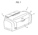
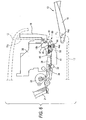
- a printer 1 is provided with a feeder 2 at the rear part thereof, on which recording paper (hereinafter, referred as paper P) is mounted in an inclined posture.
- a stacker 13 is provided on a lower casing 17 (see Fig. 5 ) which constitutes a bottom section of the printer 1.
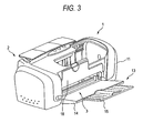
- the stacker 13 includes a stacker body 14 and a substacker 15, and is pivotable about a pivot shaft 14a (see Fig. 5 ) between a closed position shown in Fig. 1 and an opened position shown in Fig. 3 .
- An upper center part of a housing 11, a cover 12 is provided.
- the cover 12 is opened when the operation for replacing an ink cartridge is performed, for example.
- the feeder 2 comprises a hopper 21, a feeding roller 23, a retard roller 27, and guide rollers 25, 26 to feed paper P one by one toward a transporter 300 disposed an upstream side of a recording head 39.
- the transporter 300 comprises a drive roller 33 and a follower roller 34 which is brought into press contact with the drive roller 33 to be rotated by the rotation of the drive roller 33.
- the hopper 21 is a plate-shaped member which is pivotable about a not-shown pivot center provided at an upper end portion thereof.
- the feeding roller 23 has a D-shaped cross section such that an arcuate portion comes in contact with the paper P to be fed to the downstream side of the paper transporting path.
- the rotation of the feeding roller 23 is so controlled that a flat portion opposes to the paper P when the paper P is nipped between the drive roller 33 and the follower roller 34, in order to reduce the transportation resistance. This condition is shown in Fig. 2 .
- the retard roller 27 is configured so as to come in press contact with the arcuate portion of the feeding roller 23. In a case where a single sheet of the paper P is duly fed, the retard roller 27 is rotated (clockwise in Fig. 2 ) while coming in contact with the paper P. In a case where there are plural sheets of the paper P between the retard roller 27 and the feeding roller 23, the retard roller 27 is not rotated because a friction coefficient between the sheets is smaller than a friction coefficient between the retard roller 27 and the paper P. Therefore, the uppermost paper P is certainly separated from the next paper P and duly fed, thereby avoiding the overlapped feeding of the paper P.
- the guide rollers 25, 26 are freely rotatable so as to prevent the transporting resistance from generating when the paper P transported by the drive roller 33 and the follower roller 34 comes in contact with the feeding roller 23.
- the paper P fed by the feeder 2 reaches the transporter 300 while being guided by a guide member 29.
- the follower roller 34 is rotatably. supported on a holder 31.
- the holder 31 is attached on a not-shown main frame which constitutes a base body of the printer 1 by way of a not-shown spring.
- the paper P having reached the transporter 300 is transported to the downstream of the paper transporting path by the rotation of the drive roller 33 with a fixed pitch.
- the recording head 39 is disposed at the downstream side of the transporter 300.
- a platen 41 is disposed so as to oppose to the recording head 39.
- the recording head 39 is mounted on a bottom portion of a carriage 35 which is reciprocately moved in a primary scanning direction while being guided by a guide shaft 37.
- Independent ink cartridges (not shown) for a plurality colors are mounted on the carriage 35 so that the respective colors of ink are supplied to the recording head 39 within the carriage 35.
- the platen 41 for defining a distance between the paper P and the recording head 39 is formed with a plurality of ribs 43 and a plurality of recesses 42. Ink ejected to the outside of the paper P is received by an ink absorbing member (not shown) disposed within each of the recesses 42, so that a marginless printing in which printing is performed without providing any margins at the ends of the paper P can be realized. The discarded ink is lead to a waste ink tray (not shown) disposed below the platen 41 through the ink absorbing member.
- an auxiliary roller 46 and an ejector 400 comprising drive rollers 44 and follower rollers 45 at the downstream side of the recording head 39.
- the drive rollers 44 are arrayed on a rotary shaft 44a.
- the follower rollers 45 are arrayed on a frame 47 formed from a metal plate elongated in the primary scanning direction, and respectively brought into contact with the drive rollers 44 to be rotated by the rotation of the rotary shaft 44a.
- the paper P which has been subjected to the recording operation is nipped by these rollers to be ejected toward the stacker 13.
- the auxiliary roller 46 arranged at the upstream side of the ejector 400 comes in contact with the paper P from above and is rotated by the transportation of the paper P while restricting an upward movement of the paper P, thereby maintaining the distance between the paper P and the recording head 39.
- the printer 1 is adapted to perform the ink jet recording with respect to the label surface of the optical disk such as a compact disk, in addition to the above described paper P.
- the optical disk D is transported along the paper transporting path while being mounted on a plate-shaped tray T.
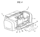
- the tray T is individually provided from the printer 1, and is inserted from the front side of the printer 1 while being guided by a tray guide 18.
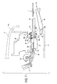
- the tray guide 18 is disposed at the downstream side of the ejector 400 so as to be pivotable between a closed (vertical) position shown in Fig. 3 and an opened (horizontal) position for supporting the tray T shown in Fig. 4 .
- Figs. 1 and 5 show a state that both of the tray guide 18 and the stacker 13 are in the closed position. In this state, since the tray guide 18 is placed inside the stacker 13, the installation space of the tray guide 18 can be reduced.
- Figs. 3 and 6 show a state that the stacker 13 is in the opened position but the tray guide 18 is in the closed position.
- Figs. 4 and 7 show a state that both of the stacker 13 and the tray guide 18 are in the opened position. In this state, the stacker 13 is slightly inclined upward to prevent the stacked paper P from being dropped.
- the printer 1 is provided with the tray guide 18 which is selectably placed in either the closed condition (non-use condition) or the opened condition (use condition) by the simple and easy pivotal movement, it is very convenient for the user because it is not necessary to attach or detach the tray guide 18 in accordance with the situations of use, and it is therefore not necessary to separately manage the tray guide 18 from the printer 1.
- the tray guide 18 closes a part of the paper transporting path when it is placed in the opened position, while the tray guide 18 is escaped from the paper transporting path when it is placed in the closed position. Therefore, the tray guide 18 in the non-use condition will not interfere with the transportation and the stacking of the normal target medium (i.e., the paper P).
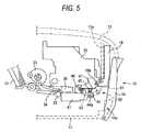
- the releaser 50 moves the follower rollers 45 between a first position at which the follower rollers 45 are brought into contact with the drive rollers 44 and a second position at which the follower rollers 45 are separated from the drive rollers 44.
- Toothed rollers which are brought into point contact with the recording surface are adopted as the follower rollers 45 to avoid the ink transfer from the recording surface.
- the releaser 50 separates the follower rollers 45 from the drive rollers 44 when the recording is performed directly onto the label surface of the optical disk D, so that the follower rollers 45 are prevented from coming in contact with the label surface of the optical disk D.
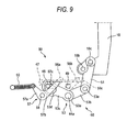
- the releaser 50 is configured such that the follower rollers 45 are separated from the drive rollers 44 interlocking with the pivotal movement of the tray guide 18 by way of a link 60.
- the link 60 comprises a link rod 51 and a link lever 53. More specifically, the link lever 53 includes a cylindrical portion 53a and lever portions 53b, 53c extended from the cylindrical portion 53a. The cylindrical portion 53a is fitted with an end of the rotary shaft 44a, so that the link lever 53 is pivotable about the rotary shaft 44a (clockwise or counterclockwise in Fig. 9 ).
- the link rod 51 is engaged with a projection 18c which is arranged in an offset position from a pivot shaft 18b of the tray guide 18, while being engaged with a projection 53e provided on the lever portion 53b of the link lever 53 so as to link the tray guide 18 and the link lever 53.
- Two guide pins 48, 49 are extended from each of longitudinal ends of the frame 47 supporting the drive rollers 45, and are loosely fitted into guide slots 56a, 56b formed in a guide plate 55 arranged adjacent to each of the longitudinal ends of the frame 47.
- the guide slots 56a, 56b are step-shaped slots.
- the frame 47 is displaced in accordance with the movement of the guide pins 48, 49 within the guide slots 56a, 5fb,. thereby changing the height position of the follower rollers 45 relative to the drive rollers 44.
- the frame 47 is configured so as to be displaced also by the link lever 53. Specifically, a hole 53d is formed in an end portion of the lever portion 53c, and the guide pin 48 is loosely fitted into the hole 53d.
- the link 60 is operated such that the lever portion 53c pushes the guide pin 48 so as to move along the guide slot 56a, thereby displacing the frame 47.
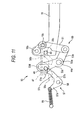
- the frame 47 slides forward (the right side in the drawings) while being displaced upward as shown in Figs. 9 to 11 . This movement is to avoid the carriage 35 which is situated immediate above the frame 47 in the condition of Fig. 9 . That is, the frame 47 can be displaced upward without colliding with the carriage 35.
- the guide pin 48 is held at positions corresponding to the first and second positions of the follower rollers 45, not by the lever portion 53c but by a V-shaped lever member 57 which is pivotable about a pivot shaft 58.
- An urging force generated by a tension spring 59 is applied to one end 57a of the lever member 57, so that the lever member 57 is pivotable counterclockwise in Fig. 9 .
- the other end 57b of the lever member 57 is engaged with the guide pin 48.
- a slope face 57c pushes the guide pin 48 toward the lower end of the guide slot 56a (the left side of the drawings) so that the follower rollers 45 are held in the first position (i.e., the position coming in contact with the drive rollers 44).
- a top face 57d pushes the guide pin 48 toward the upper end of the guide slot 56a so that the follower rollers 45 are held in the second position (i.e., the position being separated from the drive rollers 44).
- the tray guide 18 is placed at the closed position so as to extend vertically along a wall 11a which extend downward from the upper front part of the housing 11.
- the stacker 13 is also placed at the closed position so as to extend vertically along the tray guide 18.
- both of the stacker 13 and the tray guide 18 are pivoted forward to establish a condition that the tray T can be inserted from the front section of the printer 1.
- a stopper (not shown) is provided to stop the pivotal movement of the tray guide 18 such that a guide face 18a (see Fig. 4 ) extends horizontally, thereby the tray guide 18 can be horizontally led to the paper transporting path.
- the direction of the urging force that the guide pin 48 receives from the lever member 57 changes. That is, when the guide pin 48 is in contact with the slope face 57c of the lever member 57, the guide pin 48 is urged toward the lower left end of the guide slot 48, thereby holding the follower rollers 45 at the first position.
- the guide pin 48 is in contact with the top face 57d of the lever member 57, since the guide member 48 is loosely fitted with the hole 53d, it is urged toward the upper right end of the guide slot 56a, thereby holding the follower rollers 45 at the second position.
- the lever member 57 is merely urged in one direction by the single tension spring 59, the slope face 57c and the top face 57d are configured so as to be able to change the urging direction for the guide pin 48 on the other hand.
- the guide pin 49 is moved along the guide slit 56b in accordance with the displacement of the guide pin 48.
- the guide slit 56b is formed with a flat section 56c at the upper end thereof to prevent the guide pin 49 which is not provided with any urging member from displacing downward.
- Fig. 11 shows a state that the guide pin 49 is held at the flat section 56c.
- the releaser 50 comprises a bi-stabilizer in which the direction that the lever member 57 urges the guide pin 48 is switched in accordance with the pivot angle of the tray guide 18 through the use of the single tension spring 59 which urges the lever member 57 in the single direction. Accordingly, the releaser 50 can be configured with a simple structure at a low cost Although it is not shown, at the side of the other longitudinal end of the frame 47, the same releaser 50 is provided.
- the tray guide 18 for changing the height position of the driven rollers 45 must be provided with a certain precision in connection with the range of the pivotal movement, in order to establish the positional relationship shown in Fig. 5 relative to the wall 11a and the stacker 13, for example.
- the driven rollers 45 must be provided with a certain precision in order to prevent the driven rollers 45 at the first position from being pressed against the drive rollers 44 excessively, and to secure the distance between the driven rollers 45 at the second position and the label surface of the optical disk D.
- the link rod 51 and the link lever 53 for interlocking the tray guide 18 and the guide pin 48 need to be provided with high precision increasing the costs.
- the position of the guide pin 48 (the follower rollers 45) is flexibly controlled by the link 60 utilizing the urging force of the tension spring 59.
- the link rod 51 and the link rod 53 do not require so high precision, thereby reducing the costs.
- the positions of the tray guide 18 and the driven rollers 45 can be controlled irrespective of the dimensional accuracies of the link rod 51 and the link lever 53.
- the driven rollers 45 are interlockingly displaced in accordance with the pivotal movement of the tray guide 18 by way of the link 60.
- the driven rollers 45 may be interlocked with the movement of another component in the printer 1 by way of a link configured as described the above. If such a component must be provided with a certain precision for some reasons, the above described advantages can be attained effectively.
Landscapes
- Ink Jet (AREA)
- Handling Of Cut Paper (AREA)
- Handling Of Sheets (AREA)
Claims (6)
- Flüssigkeitsausstoßvorrichtung (1), umfassend:einen Flüssigkeitsausstoßkopf, der bedienbar ist, um einen Flüssigkeitstropfen in Richtung einer Zielposition auszustoßen;eine Transportiereinrichtung, die ein erstes Zielmedium (P) in Richtung der Zielposition in einer ersten Richtung transportiert;eine Ausstoßeinrichtung (400), die das erste Zielmedium (P) aus der Vorrichtung ausstoßt, wobei die Ausstoßeinrichtung (400) eine erste Rolle (44) und eine zweite Rolle (45) aufweist, die ausgebildet sind, um das erste Zielmedium (P) zu klemmen, das von der Zielposition in der ersten Richtung transportiert wurde; undeine Stapeleinrichtung (13), die flussabwärts der Ausstoßeinrichtung (400) in der ersten Richtung angeordnet ist, um zwischen einer offenen Position, in welcher sie zum Abstützen des ersten Zielmediums (P), das von der Ausstoßeinrichtung ausgestoßen wurde, angeordnet ist, und einer geschlossenen Position schwenkbar ist; gekennzeichnet durcheine Ablageführung (18), die auch flussabwärts der Ausstoßeinrichtung (400) in der ersten Richtung angeordnet ist und eine Führungsfläche aufweist, entlang derer ein Ablageelement (T), auf welchem ein zweites Zielmedium angeordnet ist, in Richtung der Zielposition in einer zweiten Richtung geführt wird, die entgegengesetzt zu der ersten Richtung ist, wobei die Ablageführung (18) zwischen einer geschlossenen Position, in welcher die Führungsfläche geschlossen ist, und einer offenen Position, in welcher die Führungsfläche geöffnet ist, um das Ablageelement (T) abzustützen, schwenkbar ist;wobei, wenn die Stapeleinrichtung (13) sich in der offenen Position befindet, es der Ablageführung (18) gestattet wird zwischen ihrer offenen und geschlossenen Position verschwenkt zu werden und, wenn die Stapeleinrichtung (13) sich in der geschlossenen Position befindet, die Ablageführung (18) in der Stapeleinrichtung (13) angeordnet wird.
- Flüssigkeitsausstoßvorrichtung nach Anspruch 1, bei der die Ablageführung (18) zum Schließen eine Abschnitts einer Bahn, durch welche das erste Zielmedium (P) transportiert wird, wenn die Ablageführung (18) in ihrer offenen Position angeordnet wird, und zum Öffnen der Bahn, wenn die Ablageführung (18) in ihrer geschlossenen Position angeordnet wird, angeordnet ist.
- Flüssigkeitsausstoßvorrichtung nach Anspruch 1, ferner umfassend eine Löseeinrichtung (50), die zum Anordnen der zweiten Rolle (45) in einer ersten Position in Kontakt mit der ersten Rolle (44), wenn die Ablageführung (18) hin zu ihrer geschlossenen Position verschwenkt wird, und in einer zweiten Position (44), die von der ersten Rolle (44) getrennt ist, wenn die Ablageführung (18) hin zu ihrer offenen Position verschwenkt wird, angeordnet ist.
- Flüssigkeitsausstoßvorrichtung nach Anspruch 3, bei der die Löseeinrichtung (50), umfasst:ein Abstützelement (47), welches die zweite Rolle abstützt;einen Führungspin (48, 49), der sich von dem Abstützelement (47) erstreckt;eine Führungsplatte (55), die mit einem Schlitz (56a, 56b), entlang welchem der Führungspin (58, 59) beweglich ist, ausgebildet ist, wobei der Schlitz ein erstes Ende, das der ersten Position der zweiten Rolle entspricht, und ein zweites Ende, das der zweiten Position der zweiten Rolle entspricht, aufweist;ein Drängelement (59); undeine Verbindung (60) mit einem Hebelelement (53), das mit dem Führungspin (48, 49) und dem Drängelement (59) in Eingriff steht, so dass der Führungspin (48, 49) in Richtung des ersten Endes des Schlitzes (56a, 56b) gedrängt wird, wenn die Ablageführung (18) in ihrer geschlossenen Position angeordnet wird, und so dass der Führungspin in Richtung des zweiten Endes des Schlitzes gedrängt wird, wenn die Ablageführung (18) in ihrer offenen Position angeordnet wird.
- Flüssigkeitsausstoßvorrichtung nach Anspruch 4, bei der:das Drängelement (59) das Hebelelement (53) in einer einzigen Richtung drängt; unddas Hebelelement (53) so ausgebildet ist, dass die Richtung, die den Führungspin (48, 49) drängt, gemäß einem Schwenkwinkel der Ablageführung (18) verändert wird.
- Flüssigkeitsausstoßvorrichtung nach Anspruch 4, bei der das Hebelelement (59) einen ersten Endabschnitt, der mit einem Loch (53d), in welches der Führungspin (48) lose eingesetzt ist, und einem zweiten Endabschnitt, in den eine rotierende Welle der ersten Rolle (44) montiert ist, um darum schwenkbar zu sein, versehen ist.
Applications Claiming Priority (8)
| Application Number | Priority Date | Filing Date | Title |
|---|---|---|---|
| JP2003317949 | 2003-09-10 | ||
| JP2003317939 | 2003-09-10 | ||
| JP2003317949 | 2003-09-10 | ||
| JP2003317939 | 2003-09-10 | ||
| JP2004256402 | 2004-09-03 | ||
| JP2004256402A JP3712237B2 (ja) | 2003-09-10 | 2004-09-03 | 記録装置、液体噴射装置 |
| JP2004256404 | 2004-09-03 | ||
| JP2004256404A JP3702900B2 (ja) | 2003-09-10 | 2004-09-03 | 記録装置 |
Publications (3)
| Publication Number | Publication Date |
|---|---|
| EP1514693A2 EP1514693A2 (de) | 2005-03-16 |
| EP1514693A3 EP1514693A3 (de) | 2006-06-14 |
| EP1514693B1 true EP1514693B1 (de) | 2012-08-29 |
Family
ID=34139750
Family Applications (1)
| Application Number | Title | Priority Date | Filing Date |
|---|---|---|---|
| EP04021571A Expired - Lifetime EP1514693B1 (de) | 2003-09-10 | 2004-09-10 | Flüssigkeitsausstossgerät |
Country Status (3)
| Country | Link |
|---|---|
| US (4) | US7137698B2 (de) |
| EP (1) | EP1514693B1 (de) |
| CN (1) | CN1323847C (de) |
Families Citing this family (18)
| Publication number | Priority date | Publication date | Assignee | Title |
|---|---|---|---|---|
| US7137698B2 (en) * | 2003-09-10 | 2006-11-21 | Seiko Epson Corporation | Recording apparatus and liquid ejection apparatus |
| US7740348B2 (en) * | 2004-09-27 | 2010-06-22 | Seiko Epson Corporation | Liquid ejecting apparatus |
| EP1683642B1 (de) * | 2005-01-20 | 2008-03-19 | Seiko Epson Corporation | Flüssigkeitsausstossgerät |
| TWI268865B (en) * | 2005-04-27 | 2006-12-21 | Benq Corp | Star wheel releasing mechanism of printing apparatus |
| JP4748308B2 (ja) * | 2005-08-19 | 2011-08-17 | セイコーエプソン株式会社 | 被記録媒体スタッカ、記録装置、液体噴射装置 |
| KR101026917B1 (ko) * | 2006-06-30 | 2011-04-04 | 노틸러스효성 주식회사 | 금융자동화기기의 스택롤러 회전방지장치 |
| US8177445B2 (en) * | 2008-04-01 | 2012-05-15 | Hewlett-Packard Development Company, L.P. | Over-center mechanism |
| JP2009269725A (ja) * | 2008-05-08 | 2009-11-19 | Canon Inc | 記録装置 |
| JP5164677B2 (ja) * | 2008-06-09 | 2013-03-21 | キヤノン株式会社 | 記録装置 |
| JP5234021B2 (ja) * | 2010-01-29 | 2013-07-10 | ブラザー工業株式会社 | 画像記録装置 |
| JP5515857B2 (ja) * | 2010-03-01 | 2014-06-11 | セイコーエプソン株式会社 | 液体噴射装置及び液体噴射ヘッドの制御方法 |
| JP4998626B2 (ja) * | 2010-03-31 | 2012-08-15 | ブラザー工業株式会社 | 画像記録装置 |
| JP5499910B2 (ja) * | 2010-05-31 | 2014-05-21 | ブラザー工業株式会社 | 搬送装置及びこの搬送装置を備えた画像記録装置 |
| CN102452223A (zh) * | 2010-10-22 | 2012-05-16 | 研能科技股份有限公司 | 可携式无线微型打印机 |
| JP5459202B2 (ja) | 2010-12-28 | 2014-04-02 | ブラザー工業株式会社 | インクジェット記録装置 |
| JP5955164B2 (ja) * | 2012-08-31 | 2016-07-20 | キヤノン株式会社 | 記録装置 |
| JP6833349B2 (ja) * | 2016-05-31 | 2021-02-24 | キヤノン株式会社 | トレイ、アダプタトレイ、記録装置、情報処理装置、記録方法、情報処理方法、および記憶媒体 |
| JP7494607B2 (ja) * | 2020-07-06 | 2024-06-04 | セイコーエプソン株式会社 | 媒体排出装置、画像読取装置 |
Family Cites Families (24)
| Publication number | Priority date | Publication date | Assignee | Title |
|---|---|---|---|---|
| US4822016A (en) * | 1986-09-09 | 1989-04-18 | Ikegami Tsushinki Co., Ltd. | Sheet sorter having pivotal sheet guide and discharge linkage mechanism |
| JPH02126853U (de) | 1989-03-28 | 1990-10-18 | ||
| US5141346A (en) * | 1990-06-28 | 1992-08-25 | Brother Kogyo Kabushiki Kaisha | Sheet feeder having automatic cut-sheet feed, continuous-form feed, and manual sheet insertion modes |
| JPH0440946U (de) | 1990-08-03 | 1992-04-07 | ||
| JPH04182260A (ja) * | 1990-11-17 | 1992-06-29 | Mita Ind Co Ltd | 排紙トレイ |
| EP0620118B1 (de) * | 1993-03-24 | 1997-11-19 | Seiko Precision Inc. | Drucker mit Endlospapierzufuhr und Einzelblattzufuhr |
| JPH09249343A (ja) | 1996-03-14 | 1997-09-22 | Canon Inc | 記録装置 |
| JP3648956B2 (ja) | 1997-11-25 | 2005-05-18 | 富士ゼロックス株式会社 | 用紙トレイ機構 |
| JP2001301277A (ja) | 2000-04-19 | 2001-10-30 | Seiko Epson Corp | プリンタ |
| JP3772966B2 (ja) | 2000-10-20 | 2006-05-10 | セイコーエプソン株式会社 | 排紙従動ローラ用ホルダおよび排紙装置並びに該排紙装置を備えた記録装置 |
| JP2002344690A (ja) * | 2001-05-14 | 2002-11-29 | Canon Inc | シート搬送装置及びファクシミリ装置 |
| JP3915437B2 (ja) | 2001-05-15 | 2007-05-16 | セイコーエプソン株式会社 | 通信回線を利用した色再現特性データ作成装置および方法 |
| JP3573278B2 (ja) * | 2001-05-30 | 2004-10-06 | セイコーエプソン株式会社 | インクジェット記録装置 |
| US6893176B2 (en) * | 2001-05-31 | 2005-05-17 | Orient Instrument Computer Co., Ltd. | Label printer for optical disk such as CD |
| JP3807486B2 (ja) * | 2001-10-02 | 2006-08-09 | セイコーエプソン株式会社 | 給排紙トレー、記録装置 |
| JP2003112458A (ja) | 2001-10-04 | 2003-04-15 | Seiko Epson Corp | 記録装置 |
| JP3730561B2 (ja) * | 2001-10-31 | 2006-01-05 | 京セラミタ株式会社 | 用紙搬送装置 |
| JP2003182889A (ja) | 2001-12-13 | 2003-07-03 | Ricoh Co Ltd | 画像形成装置 |
| JP3770317B2 (ja) | 2002-01-23 | 2006-04-26 | セイコーエプソン株式会社 | 記録媒体搬送用トレイ、位置決め用アダプタ、インクジェット記録装置 |
| JP3705212B2 (ja) * | 2002-01-23 | 2005-10-12 | セイコーエプソン株式会社 | インクジェット記録装置 |
| JP4196176B2 (ja) * | 2002-03-07 | 2008-12-17 | セイコーエプソン株式会社 | 光ディスクの排出装置および該排出装置を備えたインクジェット式記録装置 |
| JP2004189385A (ja) * | 2002-12-10 | 2004-07-08 | Murata Mach Ltd | 反転搬送ユニット及び画像形成装置 |
| JP2004299865A (ja) * | 2003-03-31 | 2004-10-28 | Brother Ind Ltd | 記録媒体搬送装置とそれを利用した画像形成装置 |
| US7137698B2 (en) * | 2003-09-10 | 2006-11-21 | Seiko Epson Corporation | Recording apparatus and liquid ejection apparatus |
-
2004
- 2004-09-10 US US10/937,748 patent/US7137698B2/en not_active Expired - Lifetime
- 2004-09-10 CN CNB2004100771212A patent/CN1323847C/zh not_active Expired - Fee Related
- 2004-09-10 EP EP04021571A patent/EP1514693B1/de not_active Expired - Lifetime
-
2006
- 2006-11-01 US US11/555,561 patent/US20070058024A1/en not_active Abandoned
- 2006-11-01 US US11/555,600 patent/US7547099B2/en not_active Expired - Fee Related
- 2006-11-01 US US11/555,582 patent/US7533985B2/en not_active Expired - Fee Related
Also Published As
| Publication number | Publication date |
|---|---|
| CN1323847C (zh) | 2007-07-04 |
| US7533985B2 (en) | 2009-05-19 |
| US20050093953A1 (en) | 2005-05-05 |
| EP1514693A3 (de) | 2006-06-14 |
| US20070058024A1 (en) | 2007-03-15 |
| US7137698B2 (en) | 2006-11-21 |
| US20070058025A1 (en) | 2007-03-15 |
| EP1514693A2 (de) | 2005-03-16 |
| US20070058026A1 (en) | 2007-03-15 |
| CN1597321A (zh) | 2005-03-23 |
| US7547099B2 (en) | 2009-06-16 |
Similar Documents
| Publication | Publication Date | Title |
|---|---|---|
| EP1514693B1 (de) | Flüssigkeitsausstossgerät | |
| JP4277223B2 (ja) | 給紙装置及びそれを備えた画像記録装置 | |
| US7111934B2 (en) | Recording medium feeding apparatus, recording apparatus, liquid ejecting apparatus | |
| US7618035B2 (en) | Image recording apparatus | |
| JP4120802B2 (ja) | 記録装置 | |
| EP1683642B1 (de) | Flüssigkeitsausstossgerät | |
| CN101045376B (zh) | 喷液装置 | |
| JP2006199431A (ja) | 記録装置及び液体噴射装置 | |
| US7628558B2 (en) | Transport system, recording apparatus and liquid ejection apparatus | |
| JP3712237B2 (ja) | 記録装置、液体噴射装置 | |
| CN100379575C (zh) | 具有卷筒纸输纸装置的打印机 | |
| US7731178B2 (en) | Feeding device | |
| JP2007118504A (ja) | キャリッジガイド軸支持機構及び液体噴射装置と記録装置 | |
| JP3741220B2 (ja) | 記録装置、液体噴射装置 | |
| KR100561478B1 (ko) | 2 가지 방식의 용지 픽업 시스템 | |
| JP4748308B2 (ja) | 被記録媒体スタッカ、記録装置、液体噴射装置 | |
| JP4114688B2 (ja) | 記録装置 | |
| JP3702900B2 (ja) | 記録装置 | |
| JP4666180B2 (ja) | 記録装置 | |
| JP2007313903A (ja) | 記録装置 | |
| JP5787121B2 (ja) | 記録装置 | |
| JP2008062439A (ja) | 被搬送媒体の浮き上がり規制装置、記録装置、液体噴射装置 |
Legal Events
| Date | Code | Title | Description |
|---|---|---|---|
| PUAI | Public reference made under article 153(3) epc to a published international application that has entered the european phase |
Free format text: ORIGINAL CODE: 0009012 |
|
| AK | Designated contracting states |
Kind code of ref document: A2 Designated state(s): AT BE BG CH CY CZ DE DK EE ES FI FR GB GR HU IE IT LI LU MC NL PL PT RO SE SI SK TR |
|
| AX | Request for extension of the european patent |
Extension state: AL HR LT LV MK |
|
| PUAL | Search report despatched |
Free format text: ORIGINAL CODE: 0009013 |
|
| RIC1 | Information provided on ipc code assigned before grant |
Ipc: B41J 13/02 20060101ALI20060426BHEP Ipc: B41J 11/54 20060101AFI20050107BHEP Ipc: B41J 3/407 20060101ALI20060426BHEP |
|
| AK | Designated contracting states |
Kind code of ref document: A3 Designated state(s): AT BE BG CH CY CZ DE DK EE ES FI FR GB GR HU IE IT LI LU MC NL PL PT RO SE SI SK TR |
|
| AX | Request for extension of the european patent |
Extension state: AL HR LT LV MK |
|
| 17P | Request for examination filed |
Effective date: 20060706 |
|
| AKX | Designation fees paid |
Designated state(s): AT BE BG CH CY CZ DE DK EE ES FI FR GB GR HU IE IT LI LU MC NL PL PT RO SE SI SK TR |
|
| 17Q | First examination report despatched |
Effective date: 20101025 |
|
| GRAP | Despatch of communication of intention to grant a patent |
Free format text: ORIGINAL CODE: EPIDOSNIGR1 |
|
| GRAS | Grant fee paid |
Free format text: ORIGINAL CODE: EPIDOSNIGR3 |
|
| GRAA | (expected) grant |
Free format text: ORIGINAL CODE: 0009210 |
|
| AK | Designated contracting states |
Kind code of ref document: B1 Designated state(s): AT BE BG CH CY CZ DE DK EE ES FI FR GB GR HU IE IT LI LU MC NL PL PT RO SE SI SK TR |
|
| REG | Reference to a national code |
Ref country code: GB Ref legal event code: FG4D |
|
| REG | Reference to a national code |
Ref country code: CH Ref legal event code: EP |
|
| REG | Reference to a national code |
Ref country code: AT Ref legal event code: REF Ref document number: 572845 Country of ref document: AT Kind code of ref document: T Effective date: 20120915 |
|
| REG | Reference to a national code |
Ref country code: IE Ref legal event code: FG4D |
|
| REG | Reference to a national code |
Ref country code: DE Ref legal event code: R096 Ref document number: 602004039107 Country of ref document: DE Effective date: 20121025 |
|
| REG | Reference to a national code |
Ref country code: AT Ref legal event code: MK05 Ref document number: 572845 Country of ref document: AT Kind code of ref document: T Effective date: 20120829 |
|
| REG | Reference to a national code |
Ref country code: NL Ref legal event code: VDEP Effective date: 20120829 |
|
| PG25 | Lapsed in a contracting state [announced via postgrant information from national office to epo] |
Ref country code: FI Free format text: LAPSE BECAUSE OF FAILURE TO SUBMIT A TRANSLATION OF THE DESCRIPTION OR TO PAY THE FEE WITHIN THE PRESCRIBED TIME-LIMIT Effective date: 20120829 Ref country code: AT Free format text: LAPSE BECAUSE OF FAILURE TO SUBMIT A TRANSLATION OF THE DESCRIPTION OR TO PAY THE FEE WITHIN THE PRESCRIBED TIME-LIMIT Effective date: 20120829 Ref country code: CY Free format text: LAPSE BECAUSE OF FAILURE TO SUBMIT A TRANSLATION OF THE DESCRIPTION OR TO PAY THE FEE WITHIN THE PRESCRIBED TIME-LIMIT Effective date: 20120829 |
|
| PG25 | Lapsed in a contracting state [announced via postgrant information from national office to epo] |
Ref country code: SE Free format text: LAPSE BECAUSE OF FAILURE TO SUBMIT A TRANSLATION OF THE DESCRIPTION OR TO PAY THE FEE WITHIN THE PRESCRIBED TIME-LIMIT Effective date: 20120829 Ref country code: BE Free format text: LAPSE BECAUSE OF FAILURE TO SUBMIT A TRANSLATION OF THE DESCRIPTION OR TO PAY THE FEE WITHIN THE PRESCRIBED TIME-LIMIT Effective date: 20120829 Ref country code: GR Free format text: LAPSE BECAUSE OF FAILURE TO SUBMIT A TRANSLATION OF THE DESCRIPTION OR TO PAY THE FEE WITHIN THE PRESCRIBED TIME-LIMIT Effective date: 20121130 Ref country code: PT Free format text: LAPSE BECAUSE OF FAILURE TO SUBMIT A TRANSLATION OF THE DESCRIPTION OR TO PAY THE FEE WITHIN THE PRESCRIBED TIME-LIMIT Effective date: 20121231 Ref country code: SI Free format text: LAPSE BECAUSE OF FAILURE TO SUBMIT A TRANSLATION OF THE DESCRIPTION OR TO PAY THE FEE WITHIN THE PRESCRIBED TIME-LIMIT Effective date: 20120829 |
|
| PG25 | Lapsed in a contracting state [announced via postgrant information from national office to epo] |
Ref country code: RO Free format text: LAPSE BECAUSE OF FAILURE TO SUBMIT A TRANSLATION OF THE DESCRIPTION OR TO PAY THE FEE WITHIN THE PRESCRIBED TIME-LIMIT Effective date: 20120829 Ref country code: ES Free format text: LAPSE BECAUSE OF FAILURE TO SUBMIT A TRANSLATION OF THE DESCRIPTION OR TO PAY THE FEE WITHIN THE PRESCRIBED TIME-LIMIT Effective date: 20121210 Ref country code: NL Free format text: LAPSE BECAUSE OF FAILURE TO SUBMIT A TRANSLATION OF THE DESCRIPTION OR TO PAY THE FEE WITHIN THE PRESCRIBED TIME-LIMIT Effective date: 20120829 Ref country code: EE Free format text: LAPSE BECAUSE OF FAILURE TO SUBMIT A TRANSLATION OF THE DESCRIPTION OR TO PAY THE FEE WITHIN THE PRESCRIBED TIME-LIMIT Effective date: 20120829 Ref country code: CZ Free format text: LAPSE BECAUSE OF FAILURE TO SUBMIT A TRANSLATION OF THE DESCRIPTION OR TO PAY THE FEE WITHIN THE PRESCRIBED TIME-LIMIT Effective date: 20120829 Ref country code: MC Free format text: LAPSE BECAUSE OF NON-PAYMENT OF DUE FEES Effective date: 20120930 Ref country code: DK Free format text: LAPSE BECAUSE OF FAILURE TO SUBMIT A TRANSLATION OF THE DESCRIPTION OR TO PAY THE FEE WITHIN THE PRESCRIBED TIME-LIMIT Effective date: 20120829 |
|
| REG | Reference to a national code |
Ref country code: CH Ref legal event code: PL |
|
| PG25 | Lapsed in a contracting state [announced via postgrant information from national office to epo] |
Ref country code: IT Free format text: LAPSE BECAUSE OF FAILURE TO SUBMIT A TRANSLATION OF THE DESCRIPTION OR TO PAY THE FEE WITHIN THE PRESCRIBED TIME-LIMIT Effective date: 20120829 Ref country code: SK Free format text: LAPSE BECAUSE OF FAILURE TO SUBMIT A TRANSLATION OF THE DESCRIPTION OR TO PAY THE FEE WITHIN THE PRESCRIBED TIME-LIMIT Effective date: 20120829 Ref country code: PL Free format text: LAPSE BECAUSE OF FAILURE TO SUBMIT A TRANSLATION OF THE DESCRIPTION OR TO PAY THE FEE WITHIN THE PRESCRIBED TIME-LIMIT Effective date: 20120829 |
|
| REG | Reference to a national code |
Ref country code: IE Ref legal event code: MM4A |
|
| PLBE | No opposition filed within time limit |
Free format text: ORIGINAL CODE: 0009261 |
|
| STAA | Information on the status of an ep patent application or granted ep patent |
Free format text: STATUS: NO OPPOSITION FILED WITHIN TIME LIMIT |
|
| GBPC | Gb: european patent ceased through non-payment of renewal fee |
Effective date: 20121129 |
|
| PG25 | Lapsed in a contracting state [announced via postgrant information from national office to epo] |
Ref country code: IE Free format text: LAPSE BECAUSE OF NON-PAYMENT OF DUE FEES Effective date: 20120910 Ref country code: BG Free format text: LAPSE BECAUSE OF FAILURE TO SUBMIT A TRANSLATION OF THE DESCRIPTION OR TO PAY THE FEE WITHIN THE PRESCRIBED TIME-LIMIT Effective date: 20121129 Ref country code: LI Free format text: LAPSE BECAUSE OF NON-PAYMENT OF DUE FEES Effective date: 20120930 Ref country code: CH Free format text: LAPSE BECAUSE OF NON-PAYMENT OF DUE FEES Effective date: 20120930 |
|
| REG | Reference to a national code |
Ref country code: FR Ref legal event code: ST Effective date: 20130628 |
|
| 26N | No opposition filed |
Effective date: 20130530 |
|
| PG25 | Lapsed in a contracting state [announced via postgrant information from national office to epo] |
Ref country code: FR Free format text: LAPSE BECAUSE OF NON-PAYMENT OF DUE FEES Effective date: 20121029 |
|
| REG | Reference to a national code |
Ref country code: DE Ref legal event code: R097 Ref document number: 602004039107 Country of ref document: DE Effective date: 20130530 |
|
| PG25 | Lapsed in a contracting state [announced via postgrant information from national office to epo] |
Ref country code: GB Free format text: LAPSE BECAUSE OF NON-PAYMENT OF DUE FEES Effective date: 20121129 |
|
| PG25 | Lapsed in a contracting state [announced via postgrant information from national office to epo] |
Ref country code: TR Free format text: LAPSE BECAUSE OF FAILURE TO SUBMIT A TRANSLATION OF THE DESCRIPTION OR TO PAY THE FEE WITHIN THE PRESCRIBED TIME-LIMIT Effective date: 20120829 |
|
| PG25 | Lapsed in a contracting state [announced via postgrant information from national office to epo] |
Ref country code: LU Free format text: LAPSE BECAUSE OF NON-PAYMENT OF DUE FEES Effective date: 20120910 |
|
| PG25 | Lapsed in a contracting state [announced via postgrant information from national office to epo] |
Ref country code: HU Free format text: LAPSE BECAUSE OF FAILURE TO SUBMIT A TRANSLATION OF THE DESCRIPTION OR TO PAY THE FEE WITHIN THE PRESCRIBED TIME-LIMIT Effective date: 20040910 |
|
| PGFP | Annual fee paid to national office [announced via postgrant information from national office to epo] |
Ref country code: DE Payment date: 20190827 Year of fee payment: 16 |
|
| REG | Reference to a national code |
Ref country code: DE Ref legal event code: R119 Ref document number: 602004039107 Country of ref document: DE |
|
| PG25 | Lapsed in a contracting state [announced via postgrant information from national office to epo] |
Ref country code: DE Free format text: LAPSE BECAUSE OF NON-PAYMENT OF DUE FEES Effective date: 20210401 |