EP1512342B1 - Vorrichtung zur Ablage und zum Transport von Gegenständen - Google Patents
Vorrichtung zur Ablage und zum Transport von Gegenständen Download PDFInfo
- Publication number
- EP1512342B1 EP1512342B1 EP04020233A EP04020233A EP1512342B1 EP 1512342 B1 EP1512342 B1 EP 1512342B1 EP 04020233 A EP04020233 A EP 04020233A EP 04020233 A EP04020233 A EP 04020233A EP 1512342 B1 EP1512342 B1 EP 1512342B1
- Authority
- EP
- European Patent Office
- Prior art keywords
- shelf
- leg
- locking
- sleeve
- legs
- Prior art date
- Legal status (The legal status is an assumption and is not a legal conclusion. Google has not performed a legal analysis and makes no representation as to the accuracy of the status listed.)
- Expired - Lifetime
Links
- 238000003860 storage Methods 0.000 claims description 17
- 239000002184 metal Substances 0.000 claims description 2
- 235000004443 Ricinus communis Nutrition 0.000 claims 2
- 240000000528 Ricinus communis Species 0.000 claims 2
- 229920002994 synthetic fiber Polymers 0.000 claims 1
- 210000001331 nose Anatomy 0.000 description 24
- 210000003128 head Anatomy 0.000 description 18
- 229920003023 plastic Polymers 0.000 description 6
- 238000011161 development Methods 0.000 description 3
- 230000018109 developmental process Effects 0.000 description 3
- 238000003892 spreading Methods 0.000 description 3
- 239000000969 carrier Substances 0.000 description 2
- 239000011521 glass Substances 0.000 description 2
- 241000511343 Chondrostoma nasus Species 0.000 description 1
- 241000209035 Ilex Species 0.000 description 1
- 230000008602 contraction Effects 0.000 description 1
- 230000001419 dependent effect Effects 0.000 description 1
- 238000010586 diagram Methods 0.000 description 1
- 238000001125 extrusion Methods 0.000 description 1
- 238000004519 manufacturing process Methods 0.000 description 1
- 238000000034 method Methods 0.000 description 1
- 230000000750 progressive effect Effects 0.000 description 1
- 230000000284 resting effect Effects 0.000 description 1
- 239000002023 wood Substances 0.000 description 1
Images


Classifications
-
- A—HUMAN NECESSITIES
- A47—FURNITURE; DOMESTIC ARTICLES OR APPLIANCES; COFFEE MILLS; SPICE MILLS; SUCTION CLEANERS IN GENERAL
- A47B—TABLES; DESKS; OFFICE FURNITURE; CABINETS; DRAWERS; GENERAL DETAILS OF FURNITURE
- A47B87/00—Sectional furniture, i.e. combinations of complete furniture units, e.g. assemblies of furniture units of the same kind such as linkable cabinets, tables, racks or shelf units
- A47B87/02—Sectional furniture, i.e. combinations of complete furniture units, e.g. assemblies of furniture units of the same kind such as linkable cabinets, tables, racks or shelf units stackable ; stackable and linkable
- A47B87/0207—Stackable racks, trays or shelf units
- A47B87/0223—Shelves stackable by means of poles or tubular members as distance-holders therebetween
-
- B—PERFORMING OPERATIONS; TRANSPORTING
- B25—HAND TOOLS; PORTABLE POWER-DRIVEN TOOLS; MANIPULATORS
- B25H—WORKSHOP EQUIPMENT, e.g. FOR MARKING-OUT WORK; STORAGE MEANS FOR WORKSHOPS
- B25H3/00—Storage means or arrangements for workshops facilitating access to, or handling of, work tools or instruments
Definitions
- the invention relates to a device for storing and transporting articles having at least two vertically spaced storage plates, in particular as a side table or as a shelf for files, tools or fixtures, wherein at least the uppermost of the shelf plates at the upper end of three or four legs is arranged, and the second or the further storage plates at the corners have recesses for the legs, which are composed of leg pieces so that the corresponding leg pieces are aligned and the heads of the respective lower leg pieces and the feet of the respective upper leg pieces to form a releasable connection in pairs are connected ,
- Devices of this type with spaced apart in at least two levels shelves are in many embodiments, For example, as a file on which particular files can be stored known. These devices can also be used as workshop trays for tools and accessories, as a side or serving table for utensils o. These devices have two spaced apart, supported by continuous legs storage plates, in which the storage plates are firmly connected to each other via aligned legs. It can be on the feet of the legs of the lower Shelf also rollers may be provided on which the device can be moved.
- the legs are composed of leg pieces, with a shelf placed on the heads of three or four leg pieces each.
- the heads of the respective lower leg pieces and the feet of the respectively associated upper leg pieces are detachably connectable to one another.
- the shelves can be separated from each other and used separately.
- the heads and feet of the associated leg pieces are plugged into each other to form a detachable connection, wherein preferably each of the pair head / foot of the associated leg pieces at one end of a nose and at the other end has a sleeve into which one of Noses can be inserted with positive locking.
- the seat can be improved by a conical design of leg piece and sleeve so that a caused by use in dimensional differences, unsafe seat is excluded.
- the locking means cooperate positively, wherein preferably the sleeve of one end of a leg piece with a rocker button with locking lug and the nose at the other end of a leg piece with a detent recess or with a self-locking Kugelgesperre between sleeve and nose are provided.
- the sleeve of a leg piece is designed as a rotary sleeve. so that it cooperates with the corresponding nose of another leg piece as a rotating bayonet, wherein rotary sleeve and nose are provided with corresponding outlets or recesses.
- the locking means cooperate non-positively, wherein preferably the sleeve slotted and slotted with means for contraction and / or the nose and are provided with means for spreading, whereby the connection securing frictional connection is achieved.
- a transparent plastic or glass plate is provided as a shelf. It is advantageous for use in the garden or terrace area when the storage plate is formed as a perforated plate.
- the inserted in the sleeve nose of the leg pieces is fixed with two locking means provided. It is advantageous if the noses and the sleeves have at least two inclined surfaces. With this training, a progressive load is achieved with increasing load, which is advantageous in particular for workshop tables or file blocks.
- foot and head of the leg piece at least one of the legs on locking means, which serve to secure the easily detachable connector itself.
- these locking means are provided on at least the leg pieces of another leg.
- the locking means are preferably arranged either in pairs next to each other or diagonally opposite one another. It goes without saying that all leg pieces of each leg may have locking means, so that on the one hand all legs solvable Lockable, and on the other hand, the attachable storage plates can also be placed turned.
- the feet of the lower shelf are provided for covering the sleeve with an insertable into this plug, which is preferably formed at least at one of the feet of the leg pieces as a leveling foot.
- the device can be aligned with ground unevenness.
- the lowermost feet of the leg pieces are provided with insertable in their sleeves, preferably designed as trailing casters.
- the nose is designed as insertable into the designed as a hollow leg leg piece to which the laterally projecting plate carrier is attached or molded as a holder for the tray.
- Such node pieces allow a rational production of the devices, even if the vertical spacing of the storage plates should be different from each other. It goes without saying that the node piece can also be formed on the corresponding leg end.
- the knot piece with plate carrier is designed as a one-piece metal die-cast or in an alternative embodiment as a one-piece plastic injection-molded piece. To cover the node piece at the head of the feet of the top of the shelf or a free-standing shelf a passport cap is provided.
- the locking means can be used as an insertable latching means, designed as a latching insert in the feet of the leg pieces.
- a secure fit is achieved by positive locking, which is further improved by conical design of locking insert and foot of leg pieces, which ensures a secure, wobble-free fit.
- the legs can be formed as a tube of any cross-section, the foot of the leg piece is formed by inserting the locking insert, the head of the leg piece by inserting the node piece.
- the laterally attached to the node piece plate carrier are designed as a holder for a shelf, which are arranged laterally of the legs at a distance from the head.
- a plate carrier plates are provided in an advantageous embodiment, on which the edge of the tray is supported.
- the plate of the plate carrier and the supported end portion of the tray on an opening and engaging in this opening projection.
- this projection is arranged on the underside of the shelf, while the plate carrier receiving this projection Opening has.
- the plate carrier is designed as a plate clamps which engage around the edge of the tray. It is advantageous if the shelf is designed to be removable from the plate carriers and used as a tray.
- At least one of the storage plates is provided with at least one gripping element on one of the sides.
- the lower and / or the upper of the storage plates on two opposite sides, preferably on the narrow sides, marginal handle elements.
- These handle elements facilitate the handling of the device, which can be better grasped and moved, further is a simple lifting of the device when driving over thresholds or other ground unevenness and lifting a top shelf possible.
- the corresponding sides of the storage plate are provided with recesses, for the arrangement of marginal gripping elements, which are formed as this Einbloodung crossing handlebars.
- the grip elements are designed as attachable plastic parts.
- the assembly is simplified, on the other hand, the handle elements can also remove again, so that the shelf - regardless of whether lower or upper shelf - can be used without handle elements.
- the shelf plate of the plate carriers is removable and usable as a tray.
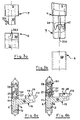
- Fig. 1 shows a device 1 for storing and transporting objects with two shelves 2.
- This shelf 2 are from each other and from their footprint by legs 4 - in the representation of Figure 1 four legs 4 - held at a distance.
- These legs are formed by leg pieces 5, at the joints of the storage plates 2 are arranged.
- At the joints of the leg pieces 5 of the foot 7 is an upper attached against the head 6 of an aligned below leg piece 5.
- the assembled at the joints legs 4 are provided at least at one of these joints with locking means which prevent unintentional release.
- Fig. 3a shows a rotating bayonet;
- the head 6 of the lower foot is provided with a receiving sleeve 36, which is designed as a rotary sleeve.
- the foot 7 of the overlying leg part has a plug-in nose 37 with a laterally projecting locking pin 37.1. If this is inserted into the slot 36.1 of the receiving sleeve 36 and this twisted, this connection is secured against unintentional loosening.
- Fig. 3b shows a frictionally secured connection.
- the intended as the head 6 of the lower foot receiving sleeve 38 is formed as a smooth socket, into which the slot nose 39 is inserted. This has a nose slot 39.1, which allows the spreading of the slot nose 39.
- An arranged in the slot nose 39 spreading spring ensures that the slot nose 39 is spread and so - used in the receiving sleeve 38 - is held in this with adhesion.
- plate supports 15 are provided on the heads 6 of the leg pieces, which hold the shelves 2. These storage plates 2 are provided with recesses 3, so that the leg pieces 5 can be joined in alignment with legs 4.
- leg pieces 5 locking inserts 20 are inserted, while the head 6 of the leg piece 5, the node piece 10 is connected, which is connected to the plate carrier 15.
- the knot piece 10 consists of the center piece 11, to which a fitting piece 12 is attached, which is directed towards the head 6 of the leg piece 5 arranged below in this form-fitting inserted - as indicated in dashed lines in Fig. 4.
- a nose 13 is attached, which is insertable into the sleeve at the foot 7 of the leg piece 5 arranged above it - indicated in dashed lines in Fig. 4.
- This nose 13 is provided with a detent recess 14 which cooperates with a locking lug of the locking inserts 20.
- the center piece 11 is provided with a plate support 15, which consists of an attached to the center piece 11 support arm 16, the free end of a plate support plate 17.1, on which rests the corner portion of the tray 2.
- a plate support 15 which consists of an attached to the center piece 11 support arm 16, the free end of a plate support plate 17.1, on which rests the corner portion of the tray 2.
- plug plate holder 18, which engage in corresponding recesses on the underside of the tray 2, ensure a safe location of this tray, which may also have a plug on the bottom, in the - here central - recess 19 of the plate support plate 17.1 engaging, this fuse can take over.
- the locking means used in the foot 7 of a leg piece 5 has a locking insert 20 which - as shown in dashed lines in FIG. 4 - is inserted in a form-fitting manner into this leg 7 by means of fitting webs 20.1 and closes off the leg piece 5 with its end flange 20.2.
- This locking insert 20 is provided with a central sleeve 21 which receives the nose 13 of the node piece 10 with positive engagement, to which both the sleeve 21 and the nose 13 are provided with cooperating conical surfaces.
- the bolt insert 20 has a rocker button 25 with lateral stub axle 26, the axle housings 22 molded into the side walls of the bolt insert 20 on both sides be recorded.
- a retaining spring 23 holds the rocker button 25 at least in the "locked" position.
- the spring 23 cooperates with a reset nose 28 so that upon actuation of the rocker button 25, the return lug 28, the spring 23 lifts, which acts after sliding over the return lug 28 on one of its inclined surfaces and thus secures the position of the rocker button 25. It goes without saying that this provision can also be designed so that the rocker button 25 can remain in the “locked” as well as in the "unlocked” position until reset.
- the rocker button 25 When used in the foot 7 of a leg piece 5 bolt insert 20, the rocker button 25 engages through an opening 7.1 in the outer wall of the tube of the leg piece 5 and is actuated.
- a recess 21.1 is provided in the central sleeve 21 which can cooperate with the locking recess 14 in the nose 13 so that the locking lug 27 engages in locked position in this locking recess while they Unlocking this is excavated.
- the storage plates 2 in their different configuration may be formed as smooth plates. It is also possible that the storage plates 2 have a profiled edge 2.1, it is also possible that the edge of the storage plates 2 is bent so that objects lying on the tray 2 are prevented from falling when moving. In order to keep these storage plates 2 in the region of the heads 6 of the leg pieces 5, they lie with their corner regions on a plate support plate 17.1; Alternatively, the corner regions of plate clamp plates 17.2 are included.
- plugs 18 are provided on the plate support plate 17, which engage in provided on the bottom of the tray 2, correspondingly formed and arranged recesses. Alternatively, the bottom of the tray 2 may have a stopper which engages in a recess of the plate support plate 17.1, - here shown as a central recess 19 - the tray position-fixing, engages.
- the tray 2 - preferably on the opposite narrow sides - a handle element, as shown in FIG. 10, 11 and 12.
- This handle may be formed as a simple grip hole 31 which is punched out, molded or worked out in any way.
- a Griffeinappelung 32 which is completed with a handle bar 33.
- Another alternative is to set up a handle element in the form of a handle strip 34 on the edge of the tray 2.
- Such a handle strip 34 can be produced in a simple manner, for example as a plastic profile, which is formed by extrusion and cut to length. This plastic handle 34 thus formed can be glued or welded to the tray 2 in the contact area to counteract unwanted detachment of the handle bar 34.
Landscapes
- Engineering & Computer Science (AREA)
- Mechanical Engineering (AREA)
- Assembled Shelves (AREA)
- Supplying Of Containers To The Packaging Station (AREA)
- Handcart (AREA)
- Pallets (AREA)
- Packaging Of Annular Or Rod-Shaped Articles, Wearing Apparel, Cassettes, Or The Like (AREA)
- Stackable Containers (AREA)
Description
- Die Erfindung betrifft eine Vorrichtung zur Ablage und zum Transport von Gegenständen mit mindestens zwei vertikal beabstandeten Ablageplatten, insbesondere als Beistelltisch oder als Ablage für Akten, Werkzeuge oder Einbauteile, wobei zumindest die oberste der Ablageplatten am oberen Ende von drei oder vier Beinen angeordnet ist, und die zweite oder die weiteren Ablageplatten an den Ecken Einnehmungen für die Beine aufweisen, die aus Beinstücken so zusammengesetzt sind, dass die korrespondierenden Beinstücke fluchten und die Köpfe der jeweils unteren Beinstücke und die Füße der jeweils oberen Beinstücke zur Bildung einer lösbaren Verbindung paarweise ineinander verbindbar sind.
- Vorrichtungen dieser Art mit in zumindest zwei Ebenen mit Abstand voneinander angeordneten Ablageplatten sind in vielen Ausführungsformen, beispielsweise als Aktenböcke auf denen insbesondere Akten abgelegt werden können, bekannt. Diese Vorrichtungen können auch als Werkstattablagen für Werkzeuge und Zubehörteile, als Beistell- oder Serviertische für Geschirr o. dgl. eingesetzt werden. Diese Vorrichtungen weisen zwei im Abstand voneinander angeordnete, von durchgehenden Beinen getragene Ablageplatten auf, bei denen die Ablageplatten über fluchtende Beine fest miteinander verbunden sind. Dabei können an den Füßen der Beine der unteren Ablageplatte auch Rollen vorgesehen sein, auf denen die Vorrichtung verfahren werden kann. Für das Verfahren ist es nachteilig, dass diese übereinander gesetzten Ablageplatten entweder fest miteinander verbunden sind, oder die Verbindung ohne weiteres voneinander lösbar ist, so dass die Mobilität der Vorrichtung, insbesondere beim Überwinden von Schwellen oder Stufen - etwa im Terrassen- oder Gartenbereich - in Frage gestellt ist. Die US 5,438,938 beschreibt eine solche Vorrichtung.
Weiter beschreibt die GB 361 781 einen Servierwagen, dessen Beine aus einer oberen Verschlusskappe, einen Mittelstück und einen Fußstück bestehen, die mittels Schrauben zwar fest, jedoch lösbar miteinander verbunden sind. Diese korrespondierenden Beinstücke sind fluchtend so zusammengesetzt, dass die Köpfe der jeweils unteren Beinstücke und die Füße der jeweils oberen Beinstücke zur Bildung einer leicht lösbaren Verbindung paarweise ineinander steckbar sind, wobei die fluchtenden Beinstücke die jeweiligen Ablageplatte an den Verbindungsstellen durchsetzen. - Daraus ergibt sich das dieser Erfindung zugrunde liegende technische Problem, unter Überwindung der Nachteile eine gattungsgemäße Vorrichtung vorzuschlagen, die mobil ist, die darüber hinaus wirtschaftlich herstellbar. einfach handhabbar und sicher einsetzbar sein soll.
- Diese Problemstellung wird für eine gattungsgemäße Vorrichtung durch die kennzeichnenden Merkmale des unabhängigen Hauptanspruchs gelöst: vorteilhafte Weiterbildungen oder bevorzugte Ausführungsformen beschreiben die abhängigen Unteransprüche.
- Um die Breite der Anwendung zu vergrößern, sind die Beine aus Beinstücken zusammengesetzt, wobei an den Köpfen von jeweils drei oder vier Beinstücken eine Ablageplatte angeordnet ist. Dabei sind die Köpfe der jeweils unteren Beinstücke und die Füße der jeweils zugeordneten oberen Beinstücke lösbar miteinander verbindbar. Dadurch können die Ablageplatten voneinander getrennt und separat benutzt werden. Vorteilhaft sind die Köpfe und Füße der einander zugeordneten Beinstücke zur Bildung einer leicht lösbaren Verbindung ineinander steckbar, wobei vorzugsweise jedes der Paare Kopf/Fuß der einander zugeordneten Beinstücke an dem einen Ende eine Nase und an dem anderen Ende eine Hülse aufweist, in die eine der Nasen mit Formschluss einführbar ist. Der Sitz kann durch eine konische Ausbildung von Beinstück und Hülse so verbessert werden, dass ein durch im Gebrauch entstehende Maßdifferenzen bedingter, unsicherer Sitz ausgeschlossen wird. Vorteilhaft sind die Hülse am Fuß des Beinstücks und die Nase am Kopf des Beinstücks angeordnet; vorteilhaft ist weiter, wenn die Verbindung der Beinstücke zumindest eine der lösbaren Verbindungen gegen unbeabsichtigtes Lösen gesperrt ist.
- In einer Ausbildung wirken die Verriegelungsmittel formschlüssig zusammen, wobei vorzugsweise die Hülse des einen Endes eines Beinstückes mit einer Wipptaste mit Rastnase und die Nase an dem anderen Ende eines Beinstückes mit einer Rastvertiefung oder mit einem selbstrastenden Kugelgesperre zwischen Hülse und Nase versehen sind. In einer weiteren Ausbildung ist die Hülse des einen Beinstückes als Drehhülse ausgebildet. so dass diese mit der dazu korrespondierenden Nase eines anderen Beinstückes als Drehbajonett zusammenwirkt, wobei Drehhülse und Nase mit einander entsprechenden Aus- oder Einnehmungen versehen sind.
- In einer alternativen Ausbildung wirken die Verriegelungsmittel kraftschlüssig zusammen, wobei vorzugsweise die Hülse geschlitzt und mit Mitteln zum Zusammenziehen und/oder die Nase geschlitzt und mit Mitteln zum Aufspreizen versehen sind, wodurch der die Verbindung sichernde Kraftschluss erreicht wird.
- Als Ablageplatten sind dabei undurchsichtige Holz-, Metall-Kunststoff- oder Glasplatten vorgesehen. In alternativer Ausbildung ist als Ablageplatte eine durchsichtige Kunststoff- oder Glasplatte vorgesehen. Vorteilhaft für die Anwendung im Garten- bzw. Terrassenbereich ist es, wenn die Ablageplatte als durchbrochene Platte ausgebildet ist.
- Bei einer bevorzugten Ausbildung ist die in der Hülse eingeführte Nase eines der Beinstücke mit zwischen beiden vorgesehenen Verriegelungsmitteln festsetzbar. Dabei ist es vorteilhaft, wenn die Nasen und die Hülsen zumindest zwei Schrägflächen aufweisen. Mit dieser Ausbildung wird ein mit zunehmender Belastung progressiver Sitz erreicht, was insbesondere für Werkstatttische oder Aktenböcke vorteilhaft ist.
- In einer vorteilhaften Weiterbildung weisen Fuß sowie Kopf des Beinstücks zumindest eines der Beine Verriegelungs-Mittel auf, die der Sicherung der an sich leicht lösbaren Steckverbindung dienen. Dadurch sind die zu Beinen fluchtend ineinander gesteckten Beinstücke so verriegelt, dass ein Abnehmen erst nach Lösen dieser Verriegelung möglich wird. So kann die Vorrichtung mit übereinander gesetzten Ablageplatten auch von der oberen Ablageplatte her angehoben werden. Vorteilhaft sind diese Verriegelungsmittel an zumindest den Beinstücken eines weiteren Beines vorgesehen. Die Verriegelungsmittel werden bevorzugt entweder paarweise nebeneinander oder diagonal gegenüberliegend angeordnet. Dabei versteht es sich von selbst, dass alle Beinstücke jedes der Beine Verriegelungsmittel aufweisen kann, so dass zum einen alle Beine lösbar verriegelbar sind, und zum anderen die aufsetzbaren Ablageplatten auch gewendet aufgesetzt werden können.
- Die Füße der unteren Ablageplatte sind zum Abdecken der Hülse mit einem in diese einsetzbaren Stopfen versehen, der vorzugsweise zumindest an einem der Füße der Beinstücke als Stellfuß ausgebildet ist. Somit kann die Vorrichtung bei Boden-Unebenheiten ausgerichtet werden. Um eine verfahrbare Vorrichtung zu erhalten, sind die untersten Füße der Beinstücke mit in deren Hülsen einsetzbare, vorzugsweise als nachlaufend ausgebildete Schwenkrollen versehen.
- Bei einer vorteilhaften Weiterbildung ist die Nase als in das als Hohlprofil ausgebildete Bein einsetzbares Knotenstück ausgebildet, an das der seitlich abstehende Plattenträger als Halter für die Ablageplatte angesetzt oder angeformt ist. Solche Knotenstücke erlauben eine rationelle Fertigung der Vorrichtungen, auch wenn der vertikale Abstand der Ablageplatten voneinander unterschiedlich sein soll. Es versteht sich dabei von selbst, dass das Knotenstück auch an das korrespondierende Bein-Ende angeformt sein kann. Das Knotenstück mit Plattenträger ist als einstückiges Metall-Druckgussstück oder in alternativer Ausführung als einstückiges Kunststoff-Spritzgussstück ausgebildet. Zum Abdecken des Knotenstücks am Kopfende der Füße der obersten der Ablageplatte oder einer freistehenden Ablageplatte ist eine Passkappe vorgesehen. Ebenfalls vorteilhaft ist es, wenn die Verriegelungsmittel als einsetzbare Rastmittel, ausgebildet als Rasteinsatz in die Füße der Beinstücke einsetzbar sind. Ein sicherer Sitz wird durch Formschluss erreicht, der durch konische Ausbildung von Rasteinsatz und Fuß der Beinstücke noch verbessert wird, was einen sicheren, wackelfreien Sitz gewährleistet. Auf diese Weise können die Beine als Rohr beliebigen Querschnitts ausgebildet sein, der Fuß des Beinstücks wird durch Einsetzen des Rasteinsatzes gebildet, der Kopf des Beinstücks durch Einsetzen des Knotenstückes.
- Die an dem Knotenstück seitlich angesetzten Plattenträger sind als Halter für eine Ablageplatte ausgebildet, die seitlich der Beine im Abstand von deren Kopf angeordnet sind. Als Plattenträger sind in einer vorteilhaften Ausbildung Teller vorgesehen, auf die der Rand der Ablageplatte abgestützt ist. Zur Sicherung der abgestützten Ablageplatte weisen der Teller des Plattenträgers und der abgestützte Endbereich der Ablageplatte eine Öffnung und einen in diese Öffnung eingreifenden Vorsprung auf. Vorteilhaft ist dieser Vorsprung an der Unterseite der Ablageplatte angeordnet, während der Plattenträger die diesen Vorsprung aufnehmende Öffnung aufweist. In einer alternativen Ausbildung ist der Plattenträger als Plattenklemmen ausgebildet, die den Rand der Ablageplatte umgreifen. Vorteilhaft ist es, wenn die Ablageplatte als von den Plattenträgern abnehmbar ausgebildet und als Tablett verwendbar ist.
- Zur besseren Handhabbarkeit ist zumindest eine der Ablageplatten mit zumindest einem Griffelement an einer der Seiten versehen. Vorteilhaft weisen dazu in einer der Ausführungsformen die untere und/oder die obere der Ablageplatten an zwei einander gegenüberliegenden Seiten, vorzugsweise an den Schmalseiten, randständige Griffelemente auf. Diese Griffelemente erleichtern das Handhaben der Vorrichtung, die sich damit besser fassen und verschieben lässt, weiter ist ein einfaches Anheben der Vorrichtung etwa beim Überfahren von Schwellen oder anderen Boden-Unebenheiten sowie ein Abheben einer oberen Ablageplatte möglich. Vorteilhaft ist es, wenn die korrespondierenden Seiten der Ablageplatte mit Einnehmungen versehen sind, zur Anordnung der randständigen Griffelemente, die als diese Einnehmung querende Griffstangen ausgebildet sind. Alternativ sind die Griffelemente als aufsteckbare Kunststoff-Teile ausgebildet. Damit wird zum einen die Montage vereinfacht, zum anderen lassen sich die Griffelemente auch wieder abnehmen, so dass die Ablageplatte - gleichgültig ob untere oder obere Ablageplatte - auch ohne Griffelemente benutzt werden kann. Bei einer vorteilhaften Weiterbildung ist die Ablageplatte von den Plattenträgern abnehmbar ausgebildet und als Tablett verwendbar.
- Die Erfindung wird an Hand der in den Figuren 1 bis 12 dargestellten Ausführungsformen beispielhaft näher beschrieben; dabei zeigen:
- Fig. 1:
- Vorrichtung mit unterer und oberer Ablageplatte (perspektivisches Schema):
- Fig. 2:
- Bein mit Nase und Hülse;
- Fig. 3:
- Verriegelungsmittel,
Fig. 3a: Formschlüssige Verriegelungsmittel,
Fig. 3b: Kraftschlüssige Verriegelungsmittel; - Fig. 4:
- Einzelheit Knotenstück mit Beinstück (abgebrochen);
- Fig. 5:
- Einzelheit Knotenstück mit aufgesetztem Bein und mit Wipptaste als Verriegelungsmittel (teil-geschnitten);
- Fig. 6:
- Einzelheit Verriegelungsmittel nach Fig. 4 (Schnitt),
Fig. 6a: Schnitt, Wipptaste gesperrt,
Fig. 6b: Schnitt, Wipptaste entsperrt; - Fig. 7:
- Knotenstück mit Auflagearm und auf Plattenteller aufliegender Ablageplatte (Ausschnitt, persp. Ansicht);
- Fig. 8:
- Einzelheit Auflagearm mit Plattenteller und aufgelegter Ablageplatte (Seitansicht):
- Fig. 9:
- Einzelheit Plattenträger als Klemmhalter mit Ablageplatte (Seitansicht);
- Fig. 10:
- Einzelheit Ablageplatte mit Grifföffnung;
- Fig. 11:
- Einzelheit Ablageplatte mit Griffeinnehmung;
- Fig. 12:
- Einzelheit Ablageplatte mit aufgesetztem Griffstück.
- Fig. 1 zeigt eine Vorrichtung 1 zur Ablage und zum Transport von Gegenständen mit zwei Ablageplatten 2. Diese Ablageplatte 2 sind voneinander sowie von ihrer Aufstandfläche durch Beine 4 - in der Darstellung der Figur 1 vier Beine 4 - in einem Abstand gehalten. Diese Beine sind von Beinstücken 5 gebildet, an deren Stoßstellen die Ablageplatten 2 angeordnet sind. An den Stoßstellen der Beinstücke 5 liegt der Fuß 7 eines oberen angesetzten gegen den Kopf 6 eines darunter fluchtend angeordneten Beinstückes 5. Die an den Stoßstellen zusammengefügten Beine 4 sind zumindest an einer dieser Stoßstellen mit Verriegelungsmittel versehen, die ein unbeabsichtigtes Lösen verhindern.
- In den Figuren 3 sind beispielhaft Verrieglungsmittel dargestellt, die formschlüssig bzw. kraftschlüssig zusammenwirken. Die Fig. 3a zeigt ein Drehbajonett; dazu ist der Kopf 6 des unteren Fußes mit einer Aufnahmehülse 36 versehen, die als Drehhülse ausgebildet ist. Der Fuß 7 des darüber befindlichen Beinteils weist eine Stecknase 37 mit einem seitlich abstehenden Verriegelungsstift 37.1 auf. Wird dieser in den Schlitz 36.1 der Aufnahmehülse 36 eingeführt und diese verdreht, ist diese Verbindung gegen unbeabsichtigtes Lösen gesichert. Die Fig. 3b zeigt eine kraftschlüssig gesicherte Verbindung. Die als am Kopf 6 des unteren Fußteils vorgesehene Aufnahmehülse 38 ist als glatte Steckhülse ausgebildet, in die die Schlitznase 39 eingesetzt wird. Diese weist einen Nasenschlitz 39.1 auf, der das Spreizen der Schlitznase 39 erlaubt. Eine in der Schlitznase 39 angeordnete Spreizfeder sorgt dafür, dass die Schlitznase 39 gespreizt wird und so - eingesetzt in die Aufnahmehülse 38 - mit Kraftschluss in dieser gehalten ist.
- In der Darstellung der Figur 1 sind an den Köpfen 6 der Beinstücke 5 Plattenträger 15 vorgesehen, die die Ablageplatten 2 halten. Diese Ablageplatten 2 sind dabei mit Einnehmungen 3 versehen, so dass die Beinstücke 5 fluchtend zu Beinen 4 zusammengefügt werden können.
- In den Fuß der - wie in Fig. 2 - 6 dargestellt - als Rohre ausgebildeten Beinstücke 5 sind Verriegelungseinsätze 20 eingesetzt, während der Kopf 6 des Beinstücks 5 das Knotenstück 10 aufnimmt, das mit dem Plattenträger 15 verbunden ist. Das Knotenstück 10 besteht aus dem Mittelstück 11, an das ein Passstück 12 angesetzt ist, das zum Kopf 6 des darunter angeordneten Beinstücks 5 hin gerichtet in diesen formschlüssig einführbar ist - wie in Fig. 4 kurz gestrichelt angedeutet. Zum Fuß 7 des Beinstücks 5 des darüber angeordneten Beinstücks 5 hin ist eine Nase 13 angesetzt, die in die Hülse am Fuß 7 des darüber angeordneten Beinstücks 5 einführbar ist - in Fig. 4 lang gestrichelt angedeutet. Diese Nase 13 ist mit einer Rastvertiefung 14 versehen, die mit einer Rastnase der Verriegelungseinsätze 20, zusammenwirkt.
- Weiter ist das Mittelstück 11 mit einem Plattenträger 15 versehen, der aus einem an das Mittelstück 11 angesetzten Trägerarm 16 besteht, dessen freies Ende einen Plattenauflageteller 17.1 aufweist, auf das der Eckbereich der Ablageplatte 2 aufliegt. Als vorstehende Stopfen ausgebildete Plattenhalter 18, die in entsprechende Rücksprünge an der Unterseite der Ablageplatte 2 eingreifen, sorgen für eine sichere Lage dieser Ablageplatte, wobei diese an der Unterseite auch einen Stopfen aufweisen kann, der in die - hier zentrale - Ausnehmung 19 des Plattenauflagetellers 17.1 eingreifend, diese Sicherung übernehmen kann.
- Das in den Fuß 7 eines Beinstücks 5 eingesetzte Verriegelungsmittel weist einen Riegeleinsatz 20 auf, der - wie in Fig. 4 kurz gestrichelt angedeutet - mittels Passstegen 20.1 formschlüssig in diesen Fuß 7 eingesetzt ist und mit seinem Abschlussflansch 20.2 das Beinstück 5 abschließt. Dieser Riegeleinsatz 20 ist mit einer zentralen Hülse 21 versehen, die die Nase 13 des Knotenstücks 10 mit Formschluss aufnimmt, wozu sowohl die Hülse 21 wie auch die Nase 13 mit miteinander zusammenwirkenden konischen Flächen versehen sind. Der Riegeleinsatz 20 weist eine Wipptaste 25 mit seitlichen Achsstummel 26 auf, die von beidseits in die Seitenwandungen des Riegeleinsatzes 20 eingeformten Achslagerungen 22 aufgenommen werden. Eine Haltefeder 23 hält die Wipptaste 25 zumindest in der Stellung "verriegelt". Dazu wirkt die Feder 23 mit einer Rückstellnase 28 so zusammen, dass bei Betätigung der Wipptaste 25 die Rückstellnase 28 die Feder 23 anhebt, die nach Übergleiten der Rückstellnase 28 auf eine deren Schrägflächen wirkt und so die Stellung der Wipptaste 25 sichert. Dabei versteht es sich von selbst, dass diese Rückstellung auch so ausgebildet sein kann, dass die Wipptaste 25 sowohl in der Stellung "verriegelt" wie auch in der Stellung "entsperrt" bis zum Rückstellen verbleiben kann.
- Bei dem in den Fuß 7 eines Beinstücks 5 eingesetzten Riegeleinsatz 20 greift die Wipptaste 25 durch eine Öffnung 7.1 in der Außenwandung des Rohres des Beinstücks 5 und ist so betätigbar. Für eine auf der Rückseite der Wipptaste 25 angeordnete Sperrnase 27 ist eine Ausnehmung 21.1 in der zentralen Hülse 21 vorgesehen, die mit der Rastvertiefung 14 in der Nase 13 so zusammenwirken kann, dass die Sperrnase 27 in gesperrter Stellung in diese Rastvertiefung eingreift, während sie beim Entsperren aus dieser ausgehoben ist.
- Die Ablageplatten 2 in ihrer unterschiedlichen Ausgestaltung können als glatte Platten ausgebildet sein. Auch ist es möglich, dass die Ablageplatten 2 einen profilierten Rand 2.1 aufweisen, ebenso ist es möglich, dass der Rand der Ablageplatten 2 aufgebogen ist, damit auf der Ablageplatte 2 liegende Gegenstände beim Verschieben am Herunterfallen gehindert werden. Um diese Ablageplatten 2 im Bereich der Köpfe 6 der Beinstücke 5 zu halten, liegen diese mit ihren Eckbereichen auf einem Plattenauflageteller 17.1 auf; alternativ werden die Eckbereiche von Plattenklemmtellern 17.2 umfasst. Um bei der Auflage auf dem Plattenauflageteller 17.1 die Ablageplatte 2 zu fixieren, sind am Plattenauflageteller 17.1 Stopfen 18 vorgesehen, die in auf der Unterseite der Ablageplatte 2 vorgesehene, entsprechend ausgebildete und angeordnete Ausnehmungen eingreifen. Alternativ kann auch die Unterseite der Ablageplatte 2 einen Stopfen aufweisen, der in eine Ausnehmung der Plattenauflageteller 17.1, - hier als zentrale Ausnehmung 19 dargestellt - die Ablageplatten-Lage fixierend, eingreift.
- Vorteilhaft ist es, wenn die Ablageplatte 2 - bevorzugt an den einander gegenüberliegenden Schmalseiten - ein Griffelement, wie in Fig. 10. 11 und 12 dargestellt, aufweist. Dieser Griff kann als einfaches Griffloch 31 ausgebildet sein, das ausgestanzt, eingeformt oder in einer beliebigen Weise ausgearbeitet wird. Alternativ dazu ist eine Griffeinnehmung 32, die mit einer Griffstange 33 abgeschlossen wird. Eine weitere Alternative besteht darin, ein Griffelement in Form einer Griffleiste 34 auf die Kante der Ablageplatte 2 aufzusetzen. Eine derartige Griffleiste 34 kann in einfacher Weise hergestellt werden, beispielsweise als ein Kunststoffprofil, das durch Extrusion geformt und entsprechend abgelängt wird. Diese so gebildete Griffleiste 34 aus Kunststoff kann mit der Ablageplatte 2 im Berührungsbereich verklebt oder verschweißt sein, um einem ungewollten Ablösen der Griffleiste 34 entgegen zu wirken.
Claims (13)
- Vorrichtung (1) zur Ablage und zum Transport von Gegenständen mit mindestens zwei vertikal beabstandeten Ablageplatten (2), insbesondere als Beistelltisch oder als Ablage für Akten, Werkzeuge oder Einbauteile, wobei zumindest die oberste der Ablageplatten am oberen Ende von drei oder vier Beinen (4) angeordnet ist, und die zweite oder die weiteren Ablageplatten an den Ecken Einnehmungen (3) für die Beine aufweisen, die aus Beinstücken (5) so zusammengesetzt sind, dass die korrespondierenden Beinstücke (5) fluchten und die Köpfe (6) der jeweils unteren Beinstücke (5) und die Füße (7) der jeweils oberen Beinstücke (5) zur Bildung einer lösbaren Verbindung paarweise ineinander verbindbar sind, dadurch gekennzeichnet, dass die Beine (4) an ihren oberen Enden jeweils einen seitlich abstehenden Plattenträger (15) zur Aufnahme der Ablageplatten (2) aufweisen.
- Vorrichtung nach Anspruch 1, dadurch gekennzeichnet, dass die leicht lösbare Verbindung der Beine (4) formschlüssig zusammengefügt ist.
- Vorrichtung nach Anspruch 1 oder 2, dadurch gekennzeichnet, dass zumindest eines der Paare von Beinstücken (5) eines Beines (4) Verriegelungsmittel zur Sicherung der an sich lösbaren Verbindung aufweist, wobei vorzugsweise Verriegelungsmittel an den Füßen (7) und Köpfen (6) der Beinstücke (5) zumindest eines weiteren Beines (4) vorgesehen sind.
- Vorrichtung nach Anspruch 3, dadurch gekennzeichnet, dass die Verriegelungsmittel als ein in den Fuß (7) eines der Beinstücke (5) einsetzbarer Rasteinsatz (20) ausgebildet sind, der mit einer in den Kopf (6) des zugeordneten der Beinstücke (5) eingesetzten Nase (13) zusammenwirkt, wobei vorzugsweise der Rasteinsatz (20) mit Formschluss in den Fuß (7) einsetzbar ist.
- Vorrichtung nach Anspruch 3, dadurch gekennzeichnet, dass die Verriegelungsmittel formschlüssig zusammenwirken, wobei zwischen einer Hülse (21) und Nase (13) eine mit einer Rastvertiefung (14) zusammenwirkende Sperrnase (27) oder ein Kugelgesperre, oder ein mit einer als Drehhülse ausgebildeten Hülse versehener Drehbajonettverschluss vorgesehen ist, wobei die korrespondierend dazu ausgebildete Nase den zweiten Teil der Verriegelungsmittel bildet.
- Vorrichtung nach Anspruch 3, dadurch gekennzeichnet, dass die Verriegelungsmittel kraftschlüssig zusammenwirken, wobei vorzugsweise die Hülse geschlitzt und mit Mitteln zum Zusammenziehen und/oder die Nase geschlitzt und mit Mitteln zum Spreizen versehen sind.
- Vorrichtung nach einem der Ansprüche 4 bis 6, dadurch gekennzeichnet, dass die Nase (13) als in den als Hohlprofil ausgebildeten Kopf (6) des Beinstücks (5) einsetzbares Knotenstück (10) ausgebildet ist, das den seitlich abstehenden Plattenträger (15) aufweist.
- Vorrichtung nach einem der Ansprüche 1 bis 7, dadurch gekennzeichnet, dass der Plattenträger (15) mit einem endständig angeordneten Plattenauflageteller (17.1) versehen ist, auf den der Rand der Ablageplatte abgestützt ist.
- Vorrichtung nach Anspruch 8, dadurch gekennzeichnet, dass der Plattenauflageteller (17.1) zur Fixierung der aufgelegten Ablageplatte vorzugsweise eine Öffnung (19) aufweist, in die ein an der Unterseite der Ablageplatte (2) angeordneter Vorsprung eingreift, oder als endständig angeordneter Plattenklemmteller (17.2) ausgebildet ist, der den Rand der Ablageplatte umgreift.
- Vorrichtung nach einem der Ansprüche 4 bis 9, dadurch gekennzeichnet, dass der Rasteinsatz (20) mit Passstegen (20.1) und Nasenaufnahme (21) und/oder das Knotenstück (10) mit Plattenträger (15) einstückig als Metall-Druckgussteil oder als Kunststoff-Spritzgussteil ausgebildet ist.
- Vorrichtung nach einem der Ansprüche 1 bis 10, dadurch gekennzeichnet, dass eine der Ablageplatten (2) zumindest ein randständiges Griffelement, vorzugsweise zwei, an einander gegenüberliegenden Seiten, aufweisen, wobei vorzugsweise das randständige Griffelement von einem in die korrespondierende Seite der Ablageplatte (2) eingeformten Griffloch (31) oder von einer in die korrespondierende Seite der Ablageplatte (2) angeformten Einnehmung (32) gebildet ist, durch die eine Griffstange (33) geführt ist.
- Vorrichtung nach einem der Ansprüche 1 bis 11, dadurch gekennzeichnet, dass die Füße (7) des untersten Beinstücks (5) eines Beines (4) zum Abdecken der Hülse mit einem in diese einsetzbaren Stopfen versehen sind, der vorzugsweise zumindest an einem der Beine (4) als Stellfuß ausgebildet ist.
- Vorrichtung nach Anspruch 12. dadurch gekennzeichnet, dass die in die Füße (7) einzusetzenden Stopfen mit Rollen, vorzugsweise mit Schwenkrollenversehen sind.
Applications Claiming Priority (2)
| Application Number | Priority Date | Filing Date | Title |
|---|---|---|---|
| DE20313623U DE20313623U1 (de) | 2003-09-03 | 2003-09-03 | Vorrichtung zur Ablage und zum Transport von Gegenständen |
| DE20313623U | 2003-09-03 |
Publications (3)
| Publication Number | Publication Date |
|---|---|
| EP1512342A2 EP1512342A2 (de) | 2005-03-09 |
| EP1512342A3 EP1512342A3 (de) | 2005-11-02 |
| EP1512342B1 true EP1512342B1 (de) | 2007-04-18 |
Family
ID=33305318
Family Applications (1)
| Application Number | Title | Priority Date | Filing Date |
|---|---|---|---|
| EP04020233A Expired - Lifetime EP1512342B1 (de) | 2003-09-03 | 2004-08-26 | Vorrichtung zur Ablage und zum Transport von Gegenständen |
Country Status (4)
| Country | Link |
|---|---|
| US (2) | US20050046133A1 (de) |
| EP (1) | EP1512342B1 (de) |
| AT (1) | ATE359725T1 (de) |
| DE (2) | DE20313623U1 (de) |
Families Citing this family (18)
| Publication number | Priority date | Publication date | Assignee | Title |
|---|---|---|---|---|
| US6935644B1 (en) * | 2004-01-02 | 2005-08-30 | Maximo E. Oranday | Plastic bendless legs for buckets |
| USD577874S1 (en) * | 2006-04-17 | 2008-09-30 | The Vollrath Company, L.L.C. | Cart post |
| USD587421S1 (en) * | 2007-07-25 | 2009-02-24 | Ying-Chieh Liao | Side frame of a tool wagon |
| USD578269S1 (en) * | 2007-10-15 | 2008-10-07 | Rubbermaid Commercial Products Llc | Maintenance cart |
| US8857827B2 (en) * | 2008-09-11 | 2014-10-14 | Shane Chen | Manually driven cart with biased-direction rear wheels |
| USD658840S1 (en) * | 2011-05-10 | 2012-05-01 | Rosemarie Nadeau | Utility cart |
| CN102806553A (zh) * | 2012-08-29 | 2012-12-05 | 东风汽车股份有限公司 | 通用型浸涂夹具置放车 |
| EE05754B1 (et) * | 2013-02-15 | 2015-08-17 | Out Of Box Oü | Distantsliitmiksüsteem vertikaalsete moodulsüsteemide koostamiseks ja selle süsteemi kasutamine |
| CN103817669A (zh) * | 2014-01-28 | 2014-05-28 | 平湖市陈达仓储办公设备有限公司 | 一种工具柜 |
| CA2946671C (en) * | 2014-04-29 | 2022-09-13 | Julio MIARNAU FERNANDEZ | Modular structure for cardboard tower-like displays |
| CN104175301A (zh) * | 2014-07-09 | 2014-12-03 | 安徽省地坤汽车天窗科技有限公司 | 一种汽车天窗安置装置 |
| US9445662B2 (en) * | 2015-01-07 | 2016-09-20 | Floyd Design Llc | Leg assembly |
| CN106426055A (zh) * | 2016-08-31 | 2017-02-22 | 天津航天液压装备有限公司 | 一种带有弹簧支撑组件的储料架 |
| JP6920807B2 (ja) * | 2016-11-04 | 2021-08-18 | 株式会社イトーキ | ナースカート |
| CN107280293A (zh) * | 2017-08-04 | 2017-10-24 | 安徽吉乃尔电器科技有限公司 | 一种可移动的组合储物柜 |
| US11064676B2 (en) * | 2018-01-31 | 2021-07-20 | Penn-Plax, Inc. | Pet furniture apparatus and method for assembling same |
| US20220143448A1 (en) * | 2020-11-06 | 2022-05-12 | Ivan TAIGUNOV | Fitness table |
| KR102493642B1 (ko) * | 2022-10-04 | 2023-02-06 | 주식회사 코아스 | 엔드리스 스토리지 |
Family Cites Families (16)
| Publication number | Priority date | Publication date | Assignee | Title |
|---|---|---|---|---|
| GB361781A (en) * | 1931-03-23 | 1931-11-26 | Karl Oppenlaender | Collapsable dinner or tea wagon |
| GB520617A (en) * | 1938-12-28 | 1940-04-29 | Henry George Attewell | Improvements in or relating to nesting furniture |
| US2933193A (en) * | 1956-11-13 | 1960-04-19 | Rolock Inc | Corner lock construction for racks |
| US3081717A (en) * | 1962-01-10 | 1963-03-19 | Neiman Steel Equipment Co Inc | Boltless metal shelf construction with mounting clips |
| FR2503997A1 (fr) * | 1981-04-16 | 1982-10-22 | Dudouyt Jean Paul | Montant d'assemblage pour meuble demontable |
| US4644876A (en) * | 1986-05-08 | 1987-02-24 | Richard A. Noon | Knockdown table or the like |
| CH672583A5 (de) * | 1987-02-12 | 1989-12-15 | Fehlbaum & Co | |
| US4998023A (en) * | 1989-06-22 | 1991-03-05 | Lakeside Manufacturing, Inc. | Portable utility cart |
| EP0451012A1 (de) * | 1990-03-27 | 1991-10-09 | Cidelcem | Regalsystem mit abnehmbaren Ablagen |
| US5553551A (en) * | 1993-08-25 | 1996-09-10 | Crombie; Terry | Interlocking modular bench system |
| US5438938A (en) * | 1994-01-14 | 1995-08-08 | Cosco, Inc. | Cart with removable tray assembly |
| US5653457A (en) * | 1994-09-30 | 1997-08-05 | Key Functional Assessments, Inc. | Convertible table/cart apparatus |
| US6135299A (en) * | 1999-06-11 | 2000-10-24 | B 4 Enterprises, Inc. | Product display and transport rack |
| US6814362B2 (en) * | 2002-02-22 | 2004-11-09 | Wellmaster Pipe and Supply, Inc. | Quiet shelf for an agricultural cart |
| US6796565B2 (en) * | 2002-10-02 | 2004-09-28 | Jae Chul Choi | Cart for transportation |
| US7137517B2 (en) * | 2005-01-19 | 2006-11-21 | Sonoco Development Inc. | Post in post product packaging and display structure tray system |
-
2003
- 2003-09-03 DE DE20313623U patent/DE20313623U1/de not_active Expired - Lifetime
-
2004
- 2004-08-25 US US10/924,829 patent/US20050046133A1/en not_active Abandoned
- 2004-08-26 AT AT04020233T patent/ATE359725T1/de not_active IP Right Cessation
- 2004-08-26 EP EP04020233A patent/EP1512342B1/de not_active Expired - Lifetime
- 2004-08-26 DE DE502004003518T patent/DE502004003518D1/de not_active Expired - Lifetime
-
2008
- 2008-02-25 US US12/071,713 patent/US20080203689A1/en not_active Abandoned
Also Published As
| Publication number | Publication date |
|---|---|
| DE502004003518D1 (de) | 2007-05-31 |
| DE20313623U1 (de) | 2004-10-14 |
| EP1512342A3 (de) | 2005-11-02 |
| US20050046133A1 (en) | 2005-03-03 |
| ATE359725T1 (de) | 2007-05-15 |
| EP1512342A2 (de) | 2005-03-09 |
| US20080203689A1 (en) | 2008-08-28 |
Similar Documents
| Publication | Publication Date | Title |
|---|---|---|
| EP1512342B1 (de) | Vorrichtung zur Ablage und zum Transport von Gegenständen | |
| DE10160364A1 (de) | Regalsystem zur Lagerung und Archivierung von Gegenständen | |
| DE4217501A1 (de) | Mobiler medizinischer Gerätetisch | |
| EP1084658A1 (de) | Ausziehführungsgarnitur | |
| DE19506431C1 (de) | Medizinischer Gerätewagen | |
| DE3527246C1 (de) | Vorrichtung zum Ioesbaren Verbinden eines Sitzteiles mit dem Fahrzeugaufbau | |
| DE2531306C2 (de) | Wandregal | |
| DE202006000109U1 (de) | Mehrzwecktisch | |
| DE102007041030B4 (de) | Zubehörbefestigung an einem Gepäckträger eines Fahrrades, Adapter und Gepäckträger | |
| DE3021098C2 (de) | ||
| WO2019092079A1 (de) | Reinigungsfahrwagen und verfahren zu dessen montage | |
| DE19909440C1 (de) | Anordnung zur Befestigung von Regalböden | |
| EP0035595A2 (de) | Vorrichtung zur lösbaren Befestigung eines aus einem Gestell ausziehbaren Trägers | |
| DE102011000546B4 (de) | Verbindungssystem, insbesondere für Möbel | |
| DE19901374A1 (de) | Variierbares Möbelsystem | |
| DE29912138U1 (de) | Kombinationsschrank | |
| DE4410397C1 (de) | Möbel | |
| EP0611534A1 (de) | Traggestell für ein Bücherregal | |
| DE19537123A1 (de) | Fußstütze mit verstellbarer Trittplatte | |
| DE202006001279U1 (de) | Regalsystem | |
| DE202004015382U1 (de) | Aufbewahrungselement für Küchenutensilien | |
| DE19647822C1 (de) | Führungsschine zum Einbringen und Positionieren einer Montageplatte in einen Schaltschrank | |
| DE29519075U1 (de) | Beschäftigungsmittelset, insbesondere zum Arbeiten oder Spielen | |
| DE9419983U1 (de) | Werkzeugträger für Aufsteckwerkzeuge, z.B. Schrauberbits | |
| EP0284833A1 (de) | Zusammenlegbares Stehpult |
Legal Events
| Date | Code | Title | Description |
|---|---|---|---|
| PUAI | Public reference made under article 153(3) epc to a published international application that has entered the european phase |
Free format text: ORIGINAL CODE: 0009012 |
|
| AK | Designated contracting states |
Kind code of ref document: A2 Designated state(s): AT BE BG CH CY CZ DE DK EE ES FI FR GB GR HU IE IT LI LU MC NL PL PT RO SE SI SK TR |
|
| AX | Request for extension of the european patent |
Extension state: AL HR LT LV MK |
|
| PUAL | Search report despatched |
Free format text: ORIGINAL CODE: 0009013 |
|
| AK | Designated contracting states |
Kind code of ref document: A3 Designated state(s): AT BE BG CH CY CZ DE DK EE ES FI FR GB GR HU IE IT LI LU MC NL PL PT RO SE SI SK TR |
|
| AX | Request for extension of the european patent |
Extension state: AL HR LT LV MK |
|
| 17P | Request for examination filed |
Effective date: 20060211 |
|
| AKX | Designation fees paid |
Designated state(s): AT BE BG CH CY CZ DE DK EE ES FI FR GB GR HU IE IT LI LU MC NL PL PT RO SE SI SK TR |
|
| 17Q | First examination report despatched |
Effective date: 20060623 |
|
| GRAP | Despatch of communication of intention to grant a patent |
Free format text: ORIGINAL CODE: EPIDOSNIGR1 |
|
| RAP1 | Party data changed (applicant data changed or rights of an application transferred) |
Owner name: GEBR. VOM BRAUCKE GMBH & CO. KG |
|
| GRAS | Grant fee paid |
Free format text: ORIGINAL CODE: EPIDOSNIGR3 |
|
| GRAA | (expected) grant |
Free format text: ORIGINAL CODE: 0009210 |
|
| AK | Designated contracting states |
Kind code of ref document: B1 Designated state(s): AT BE BG CH CY CZ DE DK EE ES FI FR GB GR HU IE IT LI LU MC NL PL PT RO SE SI SK TR |
|
| PG25 | Lapsed in a contracting state [announced via postgrant information from national office to epo] |
Ref country code: SI Free format text: LAPSE BECAUSE OF FAILURE TO SUBMIT A TRANSLATION OF THE DESCRIPTION OR TO PAY THE FEE WITHIN THE PRESCRIBED TIME-LIMIT Effective date: 20070418 Ref country code: FI Free format text: LAPSE BECAUSE OF FAILURE TO SUBMIT A TRANSLATION OF THE DESCRIPTION OR TO PAY THE FEE WITHIN THE PRESCRIBED TIME-LIMIT Effective date: 20070418 |
|
| REG | Reference to a national code |
Ref country code: CH Ref legal event code: EP |
|
| REG | Reference to a national code |
Ref country code: IE Ref legal event code: FG4D Free format text: LANGUAGE OF EP DOCUMENT: GERMAN |
|
| REF | Corresponds to: |
Ref document number: 502004003518 Country of ref document: DE Date of ref document: 20070531 Kind code of ref document: P |
|
| GBT | Gb: translation of ep patent filed (gb section 77(6)(a)/1977) |
Effective date: 20070621 |
|
| PG25 | Lapsed in a contracting state [announced via postgrant information from national office to epo] |
Ref country code: SE Free format text: LAPSE BECAUSE OF FAILURE TO SUBMIT A TRANSLATION OF THE DESCRIPTION OR TO PAY THE FEE WITHIN THE PRESCRIBED TIME-LIMIT Effective date: 20070718 |
|
| PG25 | Lapsed in a contracting state [announced via postgrant information from national office to epo] |
Ref country code: ES Free format text: LAPSE BECAUSE OF FAILURE TO SUBMIT A TRANSLATION OF THE DESCRIPTION OR TO PAY THE FEE WITHIN THE PRESCRIBED TIME-LIMIT Effective date: 20070729 |
|
| PG25 | Lapsed in a contracting state [announced via postgrant information from national office to epo] |
Ref country code: PT Free format text: LAPSE BECAUSE OF FAILURE TO SUBMIT A TRANSLATION OF THE DESCRIPTION OR TO PAY THE FEE WITHIN THE PRESCRIBED TIME-LIMIT Effective date: 20070918 |
|
| ET | Fr: translation filed | ||
| PG25 | Lapsed in a contracting state [announced via postgrant information from national office to epo] |
Ref country code: PL Free format text: LAPSE BECAUSE OF FAILURE TO SUBMIT A TRANSLATION OF THE DESCRIPTION OR TO PAY THE FEE WITHIN THE PRESCRIBED TIME-LIMIT Effective date: 20070418 |
|
| REG | Reference to a national code |
Ref country code: IE Ref legal event code: FD4D |
|
| PG25 | Lapsed in a contracting state [announced via postgrant information from national office to epo] |
Ref country code: IE Free format text: LAPSE BECAUSE OF FAILURE TO SUBMIT A TRANSLATION OF THE DESCRIPTION OR TO PAY THE FEE WITHIN THE PRESCRIBED TIME-LIMIT Effective date: 20070418 Ref country code: DK Free format text: LAPSE BECAUSE OF FAILURE TO SUBMIT A TRANSLATION OF THE DESCRIPTION OR TO PAY THE FEE WITHIN THE PRESCRIBED TIME-LIMIT Effective date: 20070418 Ref country code: CZ Free format text: LAPSE BECAUSE OF FAILURE TO SUBMIT A TRANSLATION OF THE DESCRIPTION OR TO PAY THE FEE WITHIN THE PRESCRIBED TIME-LIMIT Effective date: 20070418 Ref country code: BG Free format text: LAPSE BECAUSE OF FAILURE TO SUBMIT A TRANSLATION OF THE DESCRIPTION OR TO PAY THE FEE WITHIN THE PRESCRIBED TIME-LIMIT Effective date: 20070718 |
|
| PLBE | No opposition filed within time limit |
Free format text: ORIGINAL CODE: 0009261 |
|
| STAA | Information on the status of an ep patent application or granted ep patent |
Free format text: STATUS: NO OPPOSITION FILED WITHIN TIME LIMIT |
|
| BERE | Be: lapsed |
Owner name: GEBR. VOM BRAUCKE G.M.B.H. & CO. KG Effective date: 20070831 |
|
| PG25 | Lapsed in a contracting state [announced via postgrant information from national office to epo] |
Ref country code: SK Free format text: LAPSE BECAUSE OF FAILURE TO SUBMIT A TRANSLATION OF THE DESCRIPTION OR TO PAY THE FEE WITHIN THE PRESCRIBED TIME-LIMIT Effective date: 20070418 |
|
| 26N | No opposition filed |
Effective date: 20080121 |
|
| PG25 | Lapsed in a contracting state [announced via postgrant information from national office to epo] |
Ref country code: MC Free format text: LAPSE BECAUSE OF NON-PAYMENT OF DUE FEES Effective date: 20070831 Ref country code: GR Free format text: LAPSE BECAUSE OF FAILURE TO SUBMIT A TRANSLATION OF THE DESCRIPTION OR TO PAY THE FEE WITHIN THE PRESCRIBED TIME-LIMIT Effective date: 20070719 |
|
| PG25 | Lapsed in a contracting state [announced via postgrant information from national office to epo] |
Ref country code: RO Free format text: LAPSE BECAUSE OF FAILURE TO SUBMIT A TRANSLATION OF THE DESCRIPTION OR TO PAY THE FEE WITHIN THE PRESCRIBED TIME-LIMIT Effective date: 20070418 |
|
| PG25 | Lapsed in a contracting state [announced via postgrant information from national office to epo] |
Ref country code: BE Free format text: LAPSE BECAUSE OF NON-PAYMENT OF DUE FEES Effective date: 20070831 |
|
| PGFP | Annual fee paid to national office [announced via postgrant information from national office to epo] |
Ref country code: NL Payment date: 20080731 Year of fee payment: 5 |
|
| PG25 | Lapsed in a contracting state [announced via postgrant information from national office to epo] |
Ref country code: AT Free format text: LAPSE BECAUSE OF NON-PAYMENT OF DUE FEES Effective date: 20070826 |
|
| PGFP | Annual fee paid to national office [announced via postgrant information from national office to epo] |
Ref country code: FR Payment date: 20080730 Year of fee payment: 5 Ref country code: IT Payment date: 20080724 Year of fee payment: 5 |
|
| PGFP | Annual fee paid to national office [announced via postgrant information from national office to epo] |
Ref country code: GB Payment date: 20080814 Year of fee payment: 5 |
|
| PG25 | Lapsed in a contracting state [announced via postgrant information from national office to epo] |
Ref country code: EE Free format text: LAPSE BECAUSE OF FAILURE TO SUBMIT A TRANSLATION OF THE DESCRIPTION OR TO PAY THE FEE WITHIN THE PRESCRIBED TIME-LIMIT Effective date: 20070418 |
|
| REG | Reference to a national code |
Ref country code: CH Ref legal event code: PL |
|
| PG25 | Lapsed in a contracting state [announced via postgrant information from national office to epo] |
Ref country code: LI Free format text: LAPSE BECAUSE OF NON-PAYMENT OF DUE FEES Effective date: 20080831 Ref country code: CH Free format text: LAPSE BECAUSE OF NON-PAYMENT OF DUE FEES Effective date: 20080831 |
|
| PG25 | Lapsed in a contracting state [announced via postgrant information from national office to epo] |
Ref country code: CY Free format text: LAPSE BECAUSE OF FAILURE TO SUBMIT A TRANSLATION OF THE DESCRIPTION OR TO PAY THE FEE WITHIN THE PRESCRIBED TIME-LIMIT Effective date: 20070418 |
|
| PG25 | Lapsed in a contracting state [announced via postgrant information from national office to epo] |
Ref country code: LU Free format text: LAPSE BECAUSE OF NON-PAYMENT OF DUE FEES Effective date: 20070826 |
|
| PG25 | Lapsed in a contracting state [announced via postgrant information from national office to epo] |
Ref country code: TR Free format text: LAPSE BECAUSE OF FAILURE TO SUBMIT A TRANSLATION OF THE DESCRIPTION OR TO PAY THE FEE WITHIN THE PRESCRIBED TIME-LIMIT Effective date: 20070418 Ref country code: HU Free format text: LAPSE BECAUSE OF FAILURE TO SUBMIT A TRANSLATION OF THE DESCRIPTION OR TO PAY THE FEE WITHIN THE PRESCRIBED TIME-LIMIT Effective date: 20071019 |
|
| REG | Reference to a national code |
Ref country code: NL Ref legal event code: V1 Effective date: 20100301 |
|
| GBPC | Gb: european patent ceased through non-payment of renewal fee |
Effective date: 20090826 |
|
| REG | Reference to a national code |
Ref country code: FR Ref legal event code: ST Effective date: 20100430 |
|
| PG25 | Lapsed in a contracting state [announced via postgrant information from national office to epo] |
Ref country code: FR Free format text: LAPSE BECAUSE OF NON-PAYMENT OF DUE FEES Effective date: 20090831 Ref country code: NL Free format text: LAPSE BECAUSE OF NON-PAYMENT OF DUE FEES Effective date: 20100301 |
|
| PG25 | Lapsed in a contracting state [announced via postgrant information from national office to epo] |
Ref country code: GB Free format text: LAPSE BECAUSE OF NON-PAYMENT OF DUE FEES Effective date: 20090826 |
|
| PGFP | Annual fee paid to national office [announced via postgrant information from national office to epo] |
Ref country code: DE Payment date: 20100721 Year of fee payment: 7 |
|
| PG25 | Lapsed in a contracting state [announced via postgrant information from national office to epo] |
Ref country code: IT Free format text: LAPSE BECAUSE OF NON-PAYMENT OF DUE FEES Effective date: 20090826 |
|
| REG | Reference to a national code |
Ref country code: DE Ref legal event code: R119 Ref document number: 502004003518 Country of ref document: DE Effective date: 20120301 |
|
| PG25 | Lapsed in a contracting state [announced via postgrant information from national office to epo] |
Ref country code: DE Free format text: LAPSE BECAUSE OF NON-PAYMENT OF DUE FEES Effective date: 20120301 |