EP1512342B1 - Moyens pour supporter et pour transporter d'objets - Google Patents
Moyens pour supporter et pour transporter d'objets Download PDFInfo
- Publication number
- EP1512342B1 EP1512342B1 EP04020233A EP04020233A EP1512342B1 EP 1512342 B1 EP1512342 B1 EP 1512342B1 EP 04020233 A EP04020233 A EP 04020233A EP 04020233 A EP04020233 A EP 04020233A EP 1512342 B1 EP1512342 B1 EP 1512342B1
- Authority
- EP
- European Patent Office
- Prior art keywords
- shelf
- leg
- locking
- sleeve
- legs
- Prior art date
- Legal status (The legal status is an assumption and is not a legal conclusion. Google has not performed a legal analysis and makes no representation as to the accuracy of the status listed.)
- Expired - Lifetime
Links
- 238000003860 storage Methods 0.000 claims description 17
- 239000002184 metal Substances 0.000 claims description 2
- 235000004443 Ricinus communis Nutrition 0.000 claims 2
- 240000000528 Ricinus communis Species 0.000 claims 2
- 229920002994 synthetic fiber Polymers 0.000 claims 1
- 210000001331 nose Anatomy 0.000 description 24
- 210000003128 head Anatomy 0.000 description 18
- 229920003023 plastic Polymers 0.000 description 6
- 238000011161 development Methods 0.000 description 3
- 230000018109 developmental process Effects 0.000 description 3
- 238000003892 spreading Methods 0.000 description 3
- 239000000969 carrier Substances 0.000 description 2
- 239000011521 glass Substances 0.000 description 2
- 241000511343 Chondrostoma nasus Species 0.000 description 1
- 241000209035 Ilex Species 0.000 description 1
- 230000008602 contraction Effects 0.000 description 1
- 230000001419 dependent effect Effects 0.000 description 1
- 238000010586 diagram Methods 0.000 description 1
- 238000001125 extrusion Methods 0.000 description 1
- 238000004519 manufacturing process Methods 0.000 description 1
- 238000000034 method Methods 0.000 description 1
- 230000000750 progressive effect Effects 0.000 description 1
- 230000000284 resting effect Effects 0.000 description 1
- 239000002023 wood Substances 0.000 description 1
Images


Classifications
-
- A—HUMAN NECESSITIES
- A47—FURNITURE; DOMESTIC ARTICLES OR APPLIANCES; COFFEE MILLS; SPICE MILLS; SUCTION CLEANERS IN GENERAL
- A47B—TABLES; DESKS; OFFICE FURNITURE; CABINETS; DRAWERS; GENERAL DETAILS OF FURNITURE
- A47B87/00—Sectional furniture, i.e. combinations of complete furniture units, e.g. assemblies of furniture units of the same kind such as linkable cabinets, tables, racks or shelf units
- A47B87/02—Sectional furniture, i.e. combinations of complete furniture units, e.g. assemblies of furniture units of the same kind such as linkable cabinets, tables, racks or shelf units stackable ; stackable and linkable
- A47B87/0207—Stackable racks, trays or shelf units
- A47B87/0223—Shelves stackable by means of poles or tubular members as distance-holders therebetween
-
- B—PERFORMING OPERATIONS; TRANSPORTING
- B25—HAND TOOLS; PORTABLE POWER-DRIVEN TOOLS; MANIPULATORS
- B25H—WORKSHOP EQUIPMENT, e.g. FOR MARKING-OUT WORK; STORAGE MEANS FOR WORKSHOPS
- B25H3/00—Storage means or arrangements for workshops facilitating access to, or handling of, work tools or instruments
Definitions
- the invention relates to a device for storing and transporting articles having at least two vertically spaced storage plates, in particular as a side table or as a shelf for files, tools or fixtures, wherein at least the uppermost of the shelf plates at the upper end of three or four legs is arranged, and the second or the further storage plates at the corners have recesses for the legs, which are composed of leg pieces so that the corresponding leg pieces are aligned and the heads of the respective lower leg pieces and the feet of the respective upper leg pieces to form a releasable connection in pairs are connected ,
- Devices of this type with spaced apart in at least two levels shelves are in many embodiments, For example, as a file on which particular files can be stored known. These devices can also be used as workshop trays for tools and accessories, as a side or serving table for utensils o. These devices have two spaced apart, supported by continuous legs storage plates, in which the storage plates are firmly connected to each other via aligned legs. It can be on the feet of the legs of the lower Shelf also rollers may be provided on which the device can be moved.
- the legs are composed of leg pieces, with a shelf placed on the heads of three or four leg pieces each.
- the heads of the respective lower leg pieces and the feet of the respectively associated upper leg pieces are detachably connectable to one another.
- the shelves can be separated from each other and used separately.
- the heads and feet of the associated leg pieces are plugged into each other to form a detachable connection, wherein preferably each of the pair head / foot of the associated leg pieces at one end of a nose and at the other end has a sleeve into which one of Noses can be inserted with positive locking.
- the seat can be improved by a conical design of leg piece and sleeve so that a caused by use in dimensional differences, unsafe seat is excluded.
- the locking means cooperate positively, wherein preferably the sleeve of one end of a leg piece with a rocker button with locking lug and the nose at the other end of a leg piece with a detent recess or with a self-locking Kugelgesperre between sleeve and nose are provided.
- the sleeve of a leg piece is designed as a rotary sleeve. so that it cooperates with the corresponding nose of another leg piece as a rotating bayonet, wherein rotary sleeve and nose are provided with corresponding outlets or recesses.
- the locking means cooperate non-positively, wherein preferably the sleeve slotted and slotted with means for contraction and / or the nose and are provided with means for spreading, whereby the connection securing frictional connection is achieved.
- a transparent plastic or glass plate is provided as a shelf. It is advantageous for use in the garden or terrace area when the storage plate is formed as a perforated plate.
- the inserted in the sleeve nose of the leg pieces is fixed with two locking means provided. It is advantageous if the noses and the sleeves have at least two inclined surfaces. With this training, a progressive load is achieved with increasing load, which is advantageous in particular for workshop tables or file blocks.
- foot and head of the leg piece at least one of the legs on locking means, which serve to secure the easily detachable connector itself.
- these locking means are provided on at least the leg pieces of another leg.
- the locking means are preferably arranged either in pairs next to each other or diagonally opposite one another. It goes without saying that all leg pieces of each leg may have locking means, so that on the one hand all legs solvable Lockable, and on the other hand, the attachable storage plates can also be placed turned.
- the feet of the lower shelf are provided for covering the sleeve with an insertable into this plug, which is preferably formed at least at one of the feet of the leg pieces as a leveling foot.
- the device can be aligned with ground unevenness.
- the lowermost feet of the leg pieces are provided with insertable in their sleeves, preferably designed as trailing casters.
- the nose is designed as insertable into the designed as a hollow leg leg piece to which the laterally projecting plate carrier is attached or molded as a holder for the tray.
- Such node pieces allow a rational production of the devices, even if the vertical spacing of the storage plates should be different from each other. It goes without saying that the node piece can also be formed on the corresponding leg end.
- the knot piece with plate carrier is designed as a one-piece metal die-cast or in an alternative embodiment as a one-piece plastic injection-molded piece. To cover the node piece at the head of the feet of the top of the shelf or a free-standing shelf a passport cap is provided.
- the locking means can be used as an insertable latching means, designed as a latching insert in the feet of the leg pieces.
- a secure fit is achieved by positive locking, which is further improved by conical design of locking insert and foot of leg pieces, which ensures a secure, wobble-free fit.
- the legs can be formed as a tube of any cross-section, the foot of the leg piece is formed by inserting the locking insert, the head of the leg piece by inserting the node piece.
- the laterally attached to the node piece plate carrier are designed as a holder for a shelf, which are arranged laterally of the legs at a distance from the head.
- a plate carrier plates are provided in an advantageous embodiment, on which the edge of the tray is supported.
- the plate of the plate carrier and the supported end portion of the tray on an opening and engaging in this opening projection.
- this projection is arranged on the underside of the shelf, while the plate carrier receiving this projection Opening has.
- the plate carrier is designed as a plate clamps which engage around the edge of the tray. It is advantageous if the shelf is designed to be removable from the plate carriers and used as a tray.
- At least one of the storage plates is provided with at least one gripping element on one of the sides.
- the lower and / or the upper of the storage plates on two opposite sides, preferably on the narrow sides, marginal handle elements.
- These handle elements facilitate the handling of the device, which can be better grasped and moved, further is a simple lifting of the device when driving over thresholds or other ground unevenness and lifting a top shelf possible.
- the corresponding sides of the storage plate are provided with recesses, for the arrangement of marginal gripping elements, which are formed as this Einbloodung crossing handlebars.
- the grip elements are designed as attachable plastic parts.
- the assembly is simplified, on the other hand, the handle elements can also remove again, so that the shelf - regardless of whether lower or upper shelf - can be used without handle elements.
- the shelf plate of the plate carriers is removable and usable as a tray.
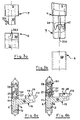
- Fig. 1 shows a device 1 for storing and transporting objects with two shelves 2.
- This shelf 2 are from each other and from their footprint by legs 4 - in the representation of Figure 1 four legs 4 - held at a distance.
- These legs are formed by leg pieces 5, at the joints of the storage plates 2 are arranged.
- At the joints of the leg pieces 5 of the foot 7 is an upper attached against the head 6 of an aligned below leg piece 5.
- the assembled at the joints legs 4 are provided at least at one of these joints with locking means which prevent unintentional release.
- Fig. 3a shows a rotating bayonet;
- the head 6 of the lower foot is provided with a receiving sleeve 36, which is designed as a rotary sleeve.
- the foot 7 of the overlying leg part has a plug-in nose 37 with a laterally projecting locking pin 37.1. If this is inserted into the slot 36.1 of the receiving sleeve 36 and this twisted, this connection is secured against unintentional loosening.
- Fig. 3b shows a frictionally secured connection.
- the intended as the head 6 of the lower foot receiving sleeve 38 is formed as a smooth socket, into which the slot nose 39 is inserted. This has a nose slot 39.1, which allows the spreading of the slot nose 39.
- An arranged in the slot nose 39 spreading spring ensures that the slot nose 39 is spread and so - used in the receiving sleeve 38 - is held in this with adhesion.
- plate supports 15 are provided on the heads 6 of the leg pieces, which hold the shelves 2. These storage plates 2 are provided with recesses 3, so that the leg pieces 5 can be joined in alignment with legs 4.
- leg pieces 5 locking inserts 20 are inserted, while the head 6 of the leg piece 5, the node piece 10 is connected, which is connected to the plate carrier 15.
- the knot piece 10 consists of the center piece 11, to which a fitting piece 12 is attached, which is directed towards the head 6 of the leg piece 5 arranged below in this form-fitting inserted - as indicated in dashed lines in Fig. 4.
- a nose 13 is attached, which is insertable into the sleeve at the foot 7 of the leg piece 5 arranged above it - indicated in dashed lines in Fig. 4.
- This nose 13 is provided with a detent recess 14 which cooperates with a locking lug of the locking inserts 20.
- the center piece 11 is provided with a plate support 15, which consists of an attached to the center piece 11 support arm 16, the free end of a plate support plate 17.1, on which rests the corner portion of the tray 2.
- a plate support 15 which consists of an attached to the center piece 11 support arm 16, the free end of a plate support plate 17.1, on which rests the corner portion of the tray 2.
- plug plate holder 18, which engage in corresponding recesses on the underside of the tray 2, ensure a safe location of this tray, which may also have a plug on the bottom, in the - here central - recess 19 of the plate support plate 17.1 engaging, this fuse can take over.
- the locking means used in the foot 7 of a leg piece 5 has a locking insert 20 which - as shown in dashed lines in FIG. 4 - is inserted in a form-fitting manner into this leg 7 by means of fitting webs 20.1 and closes off the leg piece 5 with its end flange 20.2.
- This locking insert 20 is provided with a central sleeve 21 which receives the nose 13 of the node piece 10 with positive engagement, to which both the sleeve 21 and the nose 13 are provided with cooperating conical surfaces.
- the bolt insert 20 has a rocker button 25 with lateral stub axle 26, the axle housings 22 molded into the side walls of the bolt insert 20 on both sides be recorded.
- a retaining spring 23 holds the rocker button 25 at least in the "locked" position.
- the spring 23 cooperates with a reset nose 28 so that upon actuation of the rocker button 25, the return lug 28, the spring 23 lifts, which acts after sliding over the return lug 28 on one of its inclined surfaces and thus secures the position of the rocker button 25. It goes without saying that this provision can also be designed so that the rocker button 25 can remain in the “locked” as well as in the "unlocked” position until reset.
- the rocker button 25 When used in the foot 7 of a leg piece 5 bolt insert 20, the rocker button 25 engages through an opening 7.1 in the outer wall of the tube of the leg piece 5 and is actuated.
- a recess 21.1 is provided in the central sleeve 21 which can cooperate with the locking recess 14 in the nose 13 so that the locking lug 27 engages in locked position in this locking recess while they Unlocking this is excavated.
- the storage plates 2 in their different configuration may be formed as smooth plates. It is also possible that the storage plates 2 have a profiled edge 2.1, it is also possible that the edge of the storage plates 2 is bent so that objects lying on the tray 2 are prevented from falling when moving. In order to keep these storage plates 2 in the region of the heads 6 of the leg pieces 5, they lie with their corner regions on a plate support plate 17.1; Alternatively, the corner regions of plate clamp plates 17.2 are included.
- plugs 18 are provided on the plate support plate 17, which engage in provided on the bottom of the tray 2, correspondingly formed and arranged recesses. Alternatively, the bottom of the tray 2 may have a stopper which engages in a recess of the plate support plate 17.1, - here shown as a central recess 19 - the tray position-fixing, engages.
- the tray 2 - preferably on the opposite narrow sides - a handle element, as shown in FIG. 10, 11 and 12.
- This handle may be formed as a simple grip hole 31 which is punched out, molded or worked out in any way.
- a Griffeinappelung 32 which is completed with a handle bar 33.
- Another alternative is to set up a handle element in the form of a handle strip 34 on the edge of the tray 2.
- Such a handle strip 34 can be produced in a simple manner, for example as a plastic profile, which is formed by extrusion and cut to length. This plastic handle 34 thus formed can be glued or welded to the tray 2 in the contact area to counteract unwanted detachment of the handle bar 34.
Landscapes
- Engineering & Computer Science (AREA)
- Mechanical Engineering (AREA)
- Assembled Shelves (AREA)
- Pallets (AREA)
- Packaging Of Annular Or Rod-Shaped Articles, Wearing Apparel, Cassettes, Or The Like (AREA)
- Stackable Containers (AREA)
- Handcart (AREA)
- Supplying Of Containers To The Packaging Station (AREA)
Claims (13)
- Dispositif (1) pour le support et le transport d'objets, comportant au moins deux plaques de support (2) espacées verticalement, en particulier servant de desserte ou de support pour des dossiers, outils ou éléments encastrés, dans lequel au moins la plus haute des plaques de support est disposée sur l'extrémité supérieure de trois ou quatre pattes (4), et la deuxième ou les autres plaque(s) de support présente(nt) dans les coins des évidements (3) pour les pattes, qui sont constituées de sections de patte (5), de telle sorte que les sections de patte (5) correspondantes sont alignées et les têtes (6) des sections de patte basses (5) respectives et les pieds (7) des sections de patte (5) hautes respectives peuvent être reliées les uns à l'intérieur des autres, paire par paire, de manière à obtenir un assemblage amovible, caractérisé en ce que les pattes (4) présentent, au niveau des extrémités supérieures, respectivement un élément de maintien de plaque (15) en saillie sur le côté, permettant de recevoir les plaques de support (2).
- Dispositif selon la revendication 1, caractérisé en ce que l'assemblage facilement amovible des pattes (4) est réalisé par conjugaison de formes.
- Dispositif selon la revendication 1 ou 2, caractérisé en ce qu'au moins une des paires de sections de patte (5) d'une patte (4) comporte des moyens de verrouillage permettant de sécuriser l'assemblage amovible en soi, des moyens de verrouillage étant de préférence, prévus au niveau des pieds (7) et des têtes (6) des sections de patte (5) d'au moins une autre patte (4).
- Dispositif selon la revendication 3, caractérisé en ce que les moyens de verrouillage sont configurés sous la forme d'un insert d'encliquetage (20) pouvant être inséré dans le pied (7) de l'une des sections de patte (5), lequel insert coopère avec un taquet (13) inséré dans la tête (6) de la section de patte (5) associée, l'insert d'encliquetage (20) pouvant de préférence être inséré dans le pied (7) par conjugaison de formes.
- Dispositif selon la revendication 3, caractérisé en ce que les moyens de verrouillage coopèrent par conjugaison de formes, un taquet d'arrêt (27) étant prévu entre une douille (21) et le taquet (13), et coopérant avec un évidement d'encliquetage (14), ou un encliquetage à bille, ou une fermeture à baïonnette rotative dotée d'une douille configurée sous la forme d'une douille rotative, le taquet configuré de manière correspondante formant la deuxième partie des moyens de verrouillage.
- Dispositif selon la revendication 3, caractérisé en ce que les moyens de verrouillage coopèrent par friction, la douille étant de préférence fendue et dotée de moyens de contraction et/ou le taquet étant fendu et doté de moyens d'écartement.
- Dispositif selon l'une quelconque des revendications 4 à 6, caractérisé en ce que le taquet (13) est configuré sous la forme d'un gousset (10) pouvant être inséré dans la tête (6) configurée sous forme de profilé creux de la section de patte (5), lequel gousset présente l'élément de maintien de plaque (15) en saillie sur le côté.
- Dispositif selon l'une quelconque des revendications 1 à 7, caractérisé en ce que l'élément de maintien de plaque (15) est doté d'un plateau porteur de plaque (17.1) disposé à l'extrémité, sur lequel repose le bord de la plaque de support.
- Dispositif selon la revendication 8, caractérisé en ce que le plateau porteur de plaque (17.1) présente de préférence une ouverture (19) afin de fixer la plaque de support déposée, dans laquelle ouverture mord la saillie disposée sur la face inférieure de la plaque de support (2), qui est configuré sous la forme d'un plateau de serrage de plaque (17.2) situé à l'extrémité, lequel entoure le bord de la plaque de support.
- Dispositif selon l'une quelconque des revendications 4 à 9, caractérisé en ce que l'insert d'encliquetage (20) est configuré avec des barres de raccord (20.1) et un logement de taquet (21) et/ou le gousset (10) avec l'élément de maintien de plaque (15) est configuré en une seule pièce sous la forme d'une pièce moulée par pression métallique ou d'une pièce moulée par injection en matière plastique.
- Dispositif selon l'une quelconque des revendications 1 à 10, caractérisé en ce que l'une des plaques de support (2) présente au moins un élément de préhension au niveau du bord, de préférence deux éléments de préhension sur les faces opposées l'une à l'autre, l'élément de préhension au niveau du bord étant de préférence formé par un trou de préhension (31) ménagé dans la face correspondante de la plaque de support (2) ou par un évidement (32) ménagé dans la face correspondante de la plaque de support (2), au travers duquel est guidée une barre de préhension (33).
- Dispositif selon l'une quelconque des revendications 1 à 11, caractérisé en ce que les pieds (7) de la section de patte la plus basse (5) d'une patte (4) sont dotés d'un tampon pouvant être inséré dans ceux-ci afin de recouvrir la douille, qui est de préférence configuré sous la forme d'un pied de positionnement au moins sur l'une des pattes.
- Dispositif selon la revendication 12, caractérisé en ce que les tampons devant être insérés dans les pieds (7) sont dotés de roues, de préférence de roulettes pour meubles.
Applications Claiming Priority (2)
| Application Number | Priority Date | Filing Date | Title |
|---|---|---|---|
| DE20313623U | 2003-09-03 | ||
| DE20313623U DE20313623U1 (de) | 2003-09-03 | 2003-09-03 | Vorrichtung zur Ablage und zum Transport von Gegenständen |
Publications (3)
| Publication Number | Publication Date |
|---|---|
| EP1512342A2 EP1512342A2 (fr) | 2005-03-09 |
| EP1512342A3 EP1512342A3 (fr) | 2005-11-02 |
| EP1512342B1 true EP1512342B1 (fr) | 2007-04-18 |
Family
ID=33305318
Family Applications (1)
| Application Number | Title | Priority Date | Filing Date |
|---|---|---|---|
| EP04020233A Expired - Lifetime EP1512342B1 (fr) | 2003-09-03 | 2004-08-26 | Moyens pour supporter et pour transporter d'objets |
Country Status (4)
| Country | Link |
|---|---|
| US (2) | US20050046133A1 (fr) |
| EP (1) | EP1512342B1 (fr) |
| AT (1) | ATE359725T1 (fr) |
| DE (2) | DE20313623U1 (fr) |
Families Citing this family (18)
| Publication number | Priority date | Publication date | Assignee | Title |
|---|---|---|---|---|
| US6935644B1 (en) * | 2004-01-02 | 2005-08-30 | Maximo E. Oranday | Plastic bendless legs for buckets |
| USD577874S1 (en) * | 2006-04-17 | 2008-09-30 | The Vollrath Company, L.L.C. | Cart post |
| USD587421S1 (en) * | 2007-07-25 | 2009-02-24 | Ying-Chieh Liao | Side frame of a tool wagon |
| USD578269S1 (en) * | 2007-10-15 | 2008-10-07 | Rubbermaid Commercial Products Llc | Maintenance cart |
| US8857827B2 (en) * | 2008-09-11 | 2014-10-14 | Shane Chen | Manually driven cart with biased-direction rear wheels |
| USD658840S1 (en) * | 2011-05-10 | 2012-05-01 | Rosemarie Nadeau | Utility cart |
| CN102806553A (zh) * | 2012-08-29 | 2012-12-05 | 东风汽车股份有限公司 | 通用型浸涂夹具置放车 |
| EE05754B1 (et) * | 2013-02-15 | 2015-08-17 | Out Of Box Oü | Distantsliitmiksüsteem vertikaalsete moodulsüsteemide koostamiseks ja selle süsteemi kasutamine |
| CN103817669A (zh) * | 2014-01-28 | 2014-05-28 | 平湖市陈达仓储办公设备有限公司 | 一种工具柜 |
| EP3138440B1 (fr) * | 2014-04-29 | 2018-11-07 | Miarnau Fernandez, Julio | Structure modulaire pour présentoir en carton de type tour |
| CN104175301A (zh) * | 2014-07-09 | 2014-12-03 | 安徽省地坤汽车天窗科技有限公司 | 一种汽车天窗安置装置 |
| US9445662B2 (en) * | 2015-01-07 | 2016-09-20 | Floyd Design Llc | Leg assembly |
| CN106426055A (zh) * | 2016-08-31 | 2017-02-22 | 天津航天液压装备有限公司 | 一种带有弹簧支撑组件的储料架 |
| JP6920807B2 (ja) * | 2016-11-04 | 2021-08-18 | 株式会社イトーキ | ナースカート |
| CN107280293A (zh) * | 2017-08-04 | 2017-10-24 | 安徽吉乃尔电器科技有限公司 | 一种可移动的组合储物柜 |
| US11064676B2 (en) * | 2018-01-31 | 2021-07-20 | Penn-Plax, Inc. | Pet furniture apparatus and method for assembling same |
| US20220143448A1 (en) * | 2020-11-06 | 2022-05-12 | Ivan TAIGUNOV | Fitness table |
| KR102493642B1 (ko) * | 2022-10-04 | 2023-02-06 | 주식회사 코아스 | 엔드리스 스토리지 |
Family Cites Families (16)
| Publication number | Priority date | Publication date | Assignee | Title |
|---|---|---|---|---|
| GB361781A (en) * | 1931-03-23 | 1931-11-26 | Karl Oppenlaender | Collapsable dinner or tea wagon |
| GB520617A (en) * | 1938-12-28 | 1940-04-29 | Henry George Attewell | Improvements in or relating to nesting furniture |
| US2933193A (en) * | 1956-11-13 | 1960-04-19 | Rolock Inc | Corner lock construction for racks |
| US3081717A (en) * | 1962-01-10 | 1963-03-19 | Neiman Steel Equipment Co Inc | Boltless metal shelf construction with mounting clips |
| FR2503997A1 (fr) * | 1981-04-16 | 1982-10-22 | Dudouyt Jean Paul | Montant d'assemblage pour meuble demontable |
| US4644876A (en) * | 1986-05-08 | 1987-02-24 | Richard A. Noon | Knockdown table or the like |
| CH672583A5 (fr) * | 1987-02-12 | 1989-12-15 | Fehlbaum & Co | |
| US4998023A (en) * | 1989-06-22 | 1991-03-05 | Lakeside Manufacturing, Inc. | Portable utility cart |
| EP0451012A1 (fr) * | 1990-03-27 | 1991-10-09 | Cidelcem | Système de rayonnage à plateaux amovibles |
| US5553551A (en) * | 1993-08-25 | 1996-09-10 | Crombie; Terry | Interlocking modular bench system |
| US5438938A (en) * | 1994-01-14 | 1995-08-08 | Cosco, Inc. | Cart with removable tray assembly |
| US5653457A (en) * | 1994-09-30 | 1997-08-05 | Key Functional Assessments, Inc. | Convertible table/cart apparatus |
| US6135299A (en) * | 1999-06-11 | 2000-10-24 | B 4 Enterprises, Inc. | Product display and transport rack |
| US6814362B2 (en) * | 2002-02-22 | 2004-11-09 | Wellmaster Pipe and Supply, Inc. | Quiet shelf for an agricultural cart |
| US6796565B2 (en) * | 2002-10-02 | 2004-09-28 | Jae Chul Choi | Cart for transportation |
| US7137517B2 (en) * | 2005-01-19 | 2006-11-21 | Sonoco Development Inc. | Post in post product packaging and display structure tray system |
-
2003
- 2003-09-03 DE DE20313623U patent/DE20313623U1/de not_active Expired - Lifetime
-
2004
- 2004-08-25 US US10/924,829 patent/US20050046133A1/en not_active Abandoned
- 2004-08-26 DE DE502004003518T patent/DE502004003518D1/de not_active Expired - Lifetime
- 2004-08-26 AT AT04020233T patent/ATE359725T1/de not_active IP Right Cessation
- 2004-08-26 EP EP04020233A patent/EP1512342B1/fr not_active Expired - Lifetime
-
2008
- 2008-02-25 US US12/071,713 patent/US20080203689A1/en not_active Abandoned
Also Published As
| Publication number | Publication date |
|---|---|
| ATE359725T1 (de) | 2007-05-15 |
| US20080203689A1 (en) | 2008-08-28 |
| DE20313623U1 (de) | 2004-10-14 |
| DE502004003518D1 (de) | 2007-05-31 |
| EP1512342A2 (fr) | 2005-03-09 |
| EP1512342A3 (fr) | 2005-11-02 |
| US20050046133A1 (en) | 2005-03-03 |
Similar Documents
| Publication | Publication Date | Title |
|---|---|---|
| EP1512342B1 (fr) | Moyens pour supporter et pour transporter d'objets | |
| DE10160364A1 (de) | Regalsystem zur Lagerung und Archivierung von Gegenständen | |
| DE4217501A1 (de) | Mobiler medizinischer Gerätetisch | |
| EP1084658A1 (fr) | Ensemble de glissières | |
| DE19506431C1 (de) | Medizinischer Gerätewagen | |
| DE202006019554U1 (de) | Werkzeugwagen mit Mehrfachfunktion | |
| DE3527246C1 (de) | Vorrichtung zum Ioesbaren Verbinden eines Sitzteiles mit dem Fahrzeugaufbau | |
| DE2531306C2 (de) | Wandregal | |
| DE102007041030B4 (de) | Zubehörbefestigung an einem Gepäckträger eines Fahrrades, Adapter und Gepäckträger | |
| DE3021098C2 (fr) | ||
| WO2019092079A1 (fr) | Chariot de nettoyage et son procédé de montage | |
| DE19909440C1 (de) | Anordnung zur Befestigung von Regalböden | |
| EP0035595A2 (fr) | Dispositif pour la fixation détachable d'un support extensible avec une monture | |
| DE102011000546B4 (de) | Verbindungssystem, insbesondere für Möbel | |
| DE19901374A1 (de) | Variierbares Möbelsystem | |
| DE29912138U1 (de) | Kombinationsschrank | |
| DE4410397C1 (de) | Möbel | |
| EP0611534A1 (fr) | Râtelier pour étagères de livres | |
| DE19537123A1 (de) | Fußstütze mit verstellbarer Trittplatte | |
| DE202006001279U1 (de) | Regalsystem | |
| DE202004015382U1 (de) | Aufbewahrungselement für Küchenutensilien | |
| DE19647822C1 (de) | Führungsschine zum Einbringen und Positionieren einer Montageplatte in einen Schaltschrank | |
| DE29519075U1 (de) | Beschäftigungsmittelset, insbesondere zum Arbeiten oder Spielen | |
| DE9419983U1 (de) | Werkzeugträger für Aufsteckwerkzeuge, z.B. Schrauberbits | |
| EP0284833A1 (fr) | Pupitre de lecture pliant |
Legal Events
| Date | Code | Title | Description |
|---|---|---|---|
| PUAI | Public reference made under article 153(3) epc to a published international application that has entered the european phase |
Free format text: ORIGINAL CODE: 0009012 |
|
| AK | Designated contracting states |
Kind code of ref document: A2 Designated state(s): AT BE BG CH CY CZ DE DK EE ES FI FR GB GR HU IE IT LI LU MC NL PL PT RO SE SI SK TR |
|
| AX | Request for extension of the european patent |
Extension state: AL HR LT LV MK |
|
| PUAL | Search report despatched |
Free format text: ORIGINAL CODE: 0009013 |
|
| AK | Designated contracting states |
Kind code of ref document: A3 Designated state(s): AT BE BG CH CY CZ DE DK EE ES FI FR GB GR HU IE IT LI LU MC NL PL PT RO SE SI SK TR |
|
| AX | Request for extension of the european patent |
Extension state: AL HR LT LV MK |
|
| 17P | Request for examination filed |
Effective date: 20060211 |
|
| AKX | Designation fees paid |
Designated state(s): AT BE BG CH CY CZ DE DK EE ES FI FR GB GR HU IE IT LI LU MC NL PL PT RO SE SI SK TR |
|
| 17Q | First examination report despatched |
Effective date: 20060623 |
|
| GRAP | Despatch of communication of intention to grant a patent |
Free format text: ORIGINAL CODE: EPIDOSNIGR1 |
|
| RAP1 | Party data changed (applicant data changed or rights of an application transferred) |
Owner name: GEBR. VOM BRAUCKE GMBH & CO. KG |
|
| GRAS | Grant fee paid |
Free format text: ORIGINAL CODE: EPIDOSNIGR3 |
|
| GRAA | (expected) grant |
Free format text: ORIGINAL CODE: 0009210 |
|
| AK | Designated contracting states |
Kind code of ref document: B1 Designated state(s): AT BE BG CH CY CZ DE DK EE ES FI FR GB GR HU IE IT LI LU MC NL PL PT RO SE SI SK TR |
|
| PG25 | Lapsed in a contracting state [announced via postgrant information from national office to epo] |
Ref country code: SI Free format text: LAPSE BECAUSE OF FAILURE TO SUBMIT A TRANSLATION OF THE DESCRIPTION OR TO PAY THE FEE WITHIN THE PRESCRIBED TIME-LIMIT Effective date: 20070418 Ref country code: FI Free format text: LAPSE BECAUSE OF FAILURE TO SUBMIT A TRANSLATION OF THE DESCRIPTION OR TO PAY THE FEE WITHIN THE PRESCRIBED TIME-LIMIT Effective date: 20070418 |
|
| REG | Reference to a national code |
Ref country code: CH Ref legal event code: EP |
|
| REG | Reference to a national code |
Ref country code: IE Ref legal event code: FG4D Free format text: LANGUAGE OF EP DOCUMENT: GERMAN |
|
| REF | Corresponds to: |
Ref document number: 502004003518 Country of ref document: DE Date of ref document: 20070531 Kind code of ref document: P |
|
| GBT | Gb: translation of ep patent filed (gb section 77(6)(a)/1977) |
Effective date: 20070621 |
|
| PG25 | Lapsed in a contracting state [announced via postgrant information from national office to epo] |
Ref country code: SE Free format text: LAPSE BECAUSE OF FAILURE TO SUBMIT A TRANSLATION OF THE DESCRIPTION OR TO PAY THE FEE WITHIN THE PRESCRIBED TIME-LIMIT Effective date: 20070718 |
|
| PG25 | Lapsed in a contracting state [announced via postgrant information from national office to epo] |
Ref country code: ES Free format text: LAPSE BECAUSE OF FAILURE TO SUBMIT A TRANSLATION OF THE DESCRIPTION OR TO PAY THE FEE WITHIN THE PRESCRIBED TIME-LIMIT Effective date: 20070729 |
|
| PG25 | Lapsed in a contracting state [announced via postgrant information from national office to epo] |
Ref country code: PT Free format text: LAPSE BECAUSE OF FAILURE TO SUBMIT A TRANSLATION OF THE DESCRIPTION OR TO PAY THE FEE WITHIN THE PRESCRIBED TIME-LIMIT Effective date: 20070918 |
|
| ET | Fr: translation filed | ||
| PG25 | Lapsed in a contracting state [announced via postgrant information from national office to epo] |
Ref country code: PL Free format text: LAPSE BECAUSE OF FAILURE TO SUBMIT A TRANSLATION OF THE DESCRIPTION OR TO PAY THE FEE WITHIN THE PRESCRIBED TIME-LIMIT Effective date: 20070418 |
|
| REG | Reference to a national code |
Ref country code: IE Ref legal event code: FD4D |
|
| PG25 | Lapsed in a contracting state [announced via postgrant information from national office to epo] |
Ref country code: IE Free format text: LAPSE BECAUSE OF FAILURE TO SUBMIT A TRANSLATION OF THE DESCRIPTION OR TO PAY THE FEE WITHIN THE PRESCRIBED TIME-LIMIT Effective date: 20070418 Ref country code: DK Free format text: LAPSE BECAUSE OF FAILURE TO SUBMIT A TRANSLATION OF THE DESCRIPTION OR TO PAY THE FEE WITHIN THE PRESCRIBED TIME-LIMIT Effective date: 20070418 Ref country code: CZ Free format text: LAPSE BECAUSE OF FAILURE TO SUBMIT A TRANSLATION OF THE DESCRIPTION OR TO PAY THE FEE WITHIN THE PRESCRIBED TIME-LIMIT Effective date: 20070418 Ref country code: BG Free format text: LAPSE BECAUSE OF FAILURE TO SUBMIT A TRANSLATION OF THE DESCRIPTION OR TO PAY THE FEE WITHIN THE PRESCRIBED TIME-LIMIT Effective date: 20070718 |
|
| PLBE | No opposition filed within time limit |
Free format text: ORIGINAL CODE: 0009261 |
|
| STAA | Information on the status of an ep patent application or granted ep patent |
Free format text: STATUS: NO OPPOSITION FILED WITHIN TIME LIMIT |
|
| BERE | Be: lapsed |
Owner name: GEBR. VOM BRAUCKE G.M.B.H. & CO. KG Effective date: 20070831 |
|
| PG25 | Lapsed in a contracting state [announced via postgrant information from national office to epo] |
Ref country code: SK Free format text: LAPSE BECAUSE OF FAILURE TO SUBMIT A TRANSLATION OF THE DESCRIPTION OR TO PAY THE FEE WITHIN THE PRESCRIBED TIME-LIMIT Effective date: 20070418 |
|
| 26N | No opposition filed |
Effective date: 20080121 |
|
| PG25 | Lapsed in a contracting state [announced via postgrant information from national office to epo] |
Ref country code: MC Free format text: LAPSE BECAUSE OF NON-PAYMENT OF DUE FEES Effective date: 20070831 Ref country code: GR Free format text: LAPSE BECAUSE OF FAILURE TO SUBMIT A TRANSLATION OF THE DESCRIPTION OR TO PAY THE FEE WITHIN THE PRESCRIBED TIME-LIMIT Effective date: 20070719 |
|
| PG25 | Lapsed in a contracting state [announced via postgrant information from national office to epo] |
Ref country code: RO Free format text: LAPSE BECAUSE OF FAILURE TO SUBMIT A TRANSLATION OF THE DESCRIPTION OR TO PAY THE FEE WITHIN THE PRESCRIBED TIME-LIMIT Effective date: 20070418 |
|
| PG25 | Lapsed in a contracting state [announced via postgrant information from national office to epo] |
Ref country code: BE Free format text: LAPSE BECAUSE OF NON-PAYMENT OF DUE FEES Effective date: 20070831 |
|
| PGFP | Annual fee paid to national office [announced via postgrant information from national office to epo] |
Ref country code: NL Payment date: 20080731 Year of fee payment: 5 |
|
| PG25 | Lapsed in a contracting state [announced via postgrant information from national office to epo] |
Ref country code: AT Free format text: LAPSE BECAUSE OF NON-PAYMENT OF DUE FEES Effective date: 20070826 |
|
| PGFP | Annual fee paid to national office [announced via postgrant information from national office to epo] |
Ref country code: FR Payment date: 20080730 Year of fee payment: 5 Ref country code: IT Payment date: 20080724 Year of fee payment: 5 |
|
| PGFP | Annual fee paid to national office [announced via postgrant information from national office to epo] |
Ref country code: GB Payment date: 20080814 Year of fee payment: 5 |
|
| PG25 | Lapsed in a contracting state [announced via postgrant information from national office to epo] |
Ref country code: EE Free format text: LAPSE BECAUSE OF FAILURE TO SUBMIT A TRANSLATION OF THE DESCRIPTION OR TO PAY THE FEE WITHIN THE PRESCRIBED TIME-LIMIT Effective date: 20070418 |
|
| REG | Reference to a national code |
Ref country code: CH Ref legal event code: PL |
|
| PG25 | Lapsed in a contracting state [announced via postgrant information from national office to epo] |
Ref country code: LI Free format text: LAPSE BECAUSE OF NON-PAYMENT OF DUE FEES Effective date: 20080831 Ref country code: CH Free format text: LAPSE BECAUSE OF NON-PAYMENT OF DUE FEES Effective date: 20080831 |
|
| PG25 | Lapsed in a contracting state [announced via postgrant information from national office to epo] |
Ref country code: CY Free format text: LAPSE BECAUSE OF FAILURE TO SUBMIT A TRANSLATION OF THE DESCRIPTION OR TO PAY THE FEE WITHIN THE PRESCRIBED TIME-LIMIT Effective date: 20070418 |
|
| PG25 | Lapsed in a contracting state [announced via postgrant information from national office to epo] |
Ref country code: LU Free format text: LAPSE BECAUSE OF NON-PAYMENT OF DUE FEES Effective date: 20070826 |
|
| PG25 | Lapsed in a contracting state [announced via postgrant information from national office to epo] |
Ref country code: TR Free format text: LAPSE BECAUSE OF FAILURE TO SUBMIT A TRANSLATION OF THE DESCRIPTION OR TO PAY THE FEE WITHIN THE PRESCRIBED TIME-LIMIT Effective date: 20070418 Ref country code: HU Free format text: LAPSE BECAUSE OF FAILURE TO SUBMIT A TRANSLATION OF THE DESCRIPTION OR TO PAY THE FEE WITHIN THE PRESCRIBED TIME-LIMIT Effective date: 20071019 |
|
| REG | Reference to a national code |
Ref country code: NL Ref legal event code: V1 Effective date: 20100301 |
|
| GBPC | Gb: european patent ceased through non-payment of renewal fee |
Effective date: 20090826 |
|
| REG | Reference to a national code |
Ref country code: FR Ref legal event code: ST Effective date: 20100430 |
|
| PG25 | Lapsed in a contracting state [announced via postgrant information from national office to epo] |
Ref country code: FR Free format text: LAPSE BECAUSE OF NON-PAYMENT OF DUE FEES Effective date: 20090831 Ref country code: NL Free format text: LAPSE BECAUSE OF NON-PAYMENT OF DUE FEES Effective date: 20100301 |
|
| PG25 | Lapsed in a contracting state [announced via postgrant information from national office to epo] |
Ref country code: GB Free format text: LAPSE BECAUSE OF NON-PAYMENT OF DUE FEES Effective date: 20090826 |
|
| PGFP | Annual fee paid to national office [announced via postgrant information from national office to epo] |
Ref country code: DE Payment date: 20100721 Year of fee payment: 7 |
|
| PG25 | Lapsed in a contracting state [announced via postgrant information from national office to epo] |
Ref country code: IT Free format text: LAPSE BECAUSE OF NON-PAYMENT OF DUE FEES Effective date: 20090826 |
|
| REG | Reference to a national code |
Ref country code: DE Ref legal event code: R119 Ref document number: 502004003518 Country of ref document: DE Effective date: 20120301 |
|
| PG25 | Lapsed in a contracting state [announced via postgrant information from national office to epo] |
Ref country code: DE Free format text: LAPSE BECAUSE OF NON-PAYMENT OF DUE FEES Effective date: 20120301 |