EP1511163B1 - Movable assembly for cylinder type linear motor - Google Patents
Movable assembly for cylinder type linear motor Download PDFInfo
- Publication number
- EP1511163B1 EP1511163B1 EP04255212A EP04255212A EP1511163B1 EP 1511163 B1 EP1511163 B1 EP 1511163B1 EP 04255212 A EP04255212 A EP 04255212A EP 04255212 A EP04255212 A EP 04255212A EP 1511163 B1 EP1511163 B1 EP 1511163B1
- Authority
- EP
- European Patent Office
- Prior art keywords
- electromagnetic steel
- steel plate
- direct drive
- plate pieces
- divided electromagnetic
- Prior art date
- Legal status (The legal status is an assumption and is not a legal conclusion. Google has not performed a legal analysis and makes no representation as to the accuracy of the status listed.)
- Expired - Lifetime
Links
- 229910000831 Steel Inorganic materials 0.000 claims description 185
- 239000010959 steel Substances 0.000 claims description 185
- 238000003475 lamination Methods 0.000 claims description 20
- 238000003780 insertion Methods 0.000 claims description 17
- 230000037431 insertion Effects 0.000 claims description 17
- 238000001514 detection method Methods 0.000 claims description 6
- 239000000463 material Substances 0.000 description 11
- 238000010276 construction Methods 0.000 description 9
- 230000004907 flux Effects 0.000 description 8
- 238000010030 laminating Methods 0.000 description 4
- 125000006850 spacer group Chemical group 0.000 description 4
- 238000005520 cutting process Methods 0.000 description 3
- 239000000696 magnetic material Substances 0.000 description 3
- 238000004519 manufacturing process Methods 0.000 description 3
- 238000004804 winding Methods 0.000 description 3
- 230000002542 deteriorative effect Effects 0.000 description 2
- 230000005284 excitation Effects 0.000 description 2
- 229910052751 metal Inorganic materials 0.000 description 2
- 239000002184 metal Substances 0.000 description 2
- 230000002093 peripheral effect Effects 0.000 description 2
- 229910000975 Carbon steel Inorganic materials 0.000 description 1
- XUIMIQQOPSSXEZ-UHFFFAOYSA-N Silicon Chemical compound [Si] XUIMIQQOPSSXEZ-UHFFFAOYSA-N 0.000 description 1
- 230000001133 acceleration Effects 0.000 description 1
- 229910052782 aluminium Inorganic materials 0.000 description 1
- XAGFODPZIPBFFR-UHFFFAOYSA-N aluminium Chemical compound [Al] XAGFODPZIPBFFR-UHFFFAOYSA-N 0.000 description 1
- 239000010962 carbon steel Substances 0.000 description 1
- 230000015556 catabolic process Effects 0.000 description 1
- 239000004020 conductor Substances 0.000 description 1
- 238000006731 degradation reaction Methods 0.000 description 1
- 230000000694 effects Effects 0.000 description 1
- 239000004519 grease Substances 0.000 description 1
- 230000005415 magnetization Effects 0.000 description 1
- 230000003287 optical effect Effects 0.000 description 1
- 230000002265 prevention Effects 0.000 description 1
- 229910052710 silicon Inorganic materials 0.000 description 1
- 239000010703 silicon Substances 0.000 description 1
Images




Classifications
-
- H—ELECTRICITY
- H02—GENERATION; CONVERSION OR DISTRIBUTION OF ELECTRIC POWER
- H02K—DYNAMO-ELECTRIC MACHINES
- H02K41/00—Propulsion systems in which a rigid body is moved along a path due to dynamo-electric interaction between the body and a magnetic field travelling along the path
- H02K41/02—Linear motors; Sectional motors
- H02K41/03—Synchronous motors; Motors moving step by step; Reluctance motors
-
- H—ELECTRICITY
- H02—GENERATION; CONVERSION OR DISTRIBUTION OF ELECTRIC POWER
- H02K—DYNAMO-ELECTRIC MACHINES
- H02K41/00—Propulsion systems in which a rigid body is moved along a path due to dynamo-electric interaction between the body and a magnetic field travelling along the path
- H02K41/02—Linear motors; Sectional motors
- H02K41/03—Synchronous motors; Motors moving step by step; Reluctance motors
- H02K41/031—Synchronous motors; Motors moving step by step; Reluctance motors of the permanent magnet type
-
- H—ELECTRICITY
- H02—GENERATION; CONVERSION OR DISTRIBUTION OF ELECTRIC POWER
- H02K—DYNAMO-ELECTRIC MACHINES
- H02K1/00—Details of the magnetic circuit
- H02K1/06—Details of the magnetic circuit characterised by the shape, form or construction
- H02K1/34—Reciprocating, oscillating or vibrating parts of the magnetic circuit
-
- H—ELECTRICITY
- H02—GENERATION; CONVERSION OR DISTRIBUTION OF ELECTRIC POWER
- H02K—DYNAMO-ELECTRIC MACHINES
- H02K33/00—Motors with reciprocating, oscillating or vibrating magnet, armature or coil system
- H02K33/16—Motors with reciprocating, oscillating or vibrating magnet, armature or coil system with polarised armatures moving in alternate directions by reversal or energisation of a single coil system
-
- H—ELECTRICITY
- H02—GENERATION; CONVERSION OR DISTRIBUTION OF ELECTRIC POWER
- H02K—DYNAMO-ELECTRIC MACHINES
- H02K41/00—Propulsion systems in which a rigid body is moved along a path due to dynamo-electric interaction between the body and a magnetic field travelling along the path
- H02K41/02—Linear motors; Sectional motors
-
- H—ELECTRICITY
- H02—GENERATION; CONVERSION OR DISTRIBUTION OF ELECTRIC POWER
- H02K—DYNAMO-ELECTRIC MACHINES
- H02K1/00—Details of the magnetic circuit
- H02K1/06—Details of the magnetic circuit characterised by the shape, form or construction
- H02K1/22—Rotating parts of the magnetic circuit
- H02K1/27—Rotor cores with permanent magnets
- H02K1/2706—Inner rotors
- H02K1/272—Inner rotors the magnetisation axis of the magnets being perpendicular to the rotor axis
- H02K1/274—Inner rotors the magnetisation axis of the magnets being perpendicular to the rotor axis the rotor consisting of two or more circumferentially positioned magnets
- H02K1/2753—Inner rotors the magnetisation axis of the magnets being perpendicular to the rotor axis the rotor consisting of two or more circumferentially positioned magnets the rotor consisting of magnets or groups of magnets arranged with alternating polarity
- H02K1/276—Magnets embedded in the magnetic core, e.g. interior permanent magnets [IPM]
-
- H—ELECTRICITY
- H02—GENERATION; CONVERSION OR DISTRIBUTION OF ELECTRIC POWER
- H02K—DYNAMO-ELECTRIC MACHINES
- H02K1/00—Details of the magnetic circuit
- H02K1/06—Details of the magnetic circuit characterised by the shape, form or construction
- H02K1/22—Rotating parts of the magnetic circuit
- H02K1/28—Means for mounting or fastening rotating magnetic parts on to, or to, the rotor structures
-
- H—ELECTRICITY
- H02—GENERATION; CONVERSION OR DISTRIBUTION OF ELECTRIC POWER
- H02K—DYNAMO-ELECTRIC MACHINES
- H02K1/00—Details of the magnetic circuit
- H02K1/06—Details of the magnetic circuit characterised by the shape, form or construction
- H02K1/22—Rotating parts of the magnetic circuit
- H02K1/28—Means for mounting or fastening rotating magnetic parts on to, or to, the rotor structures
- H02K1/30—Means for mounting or fastening rotating magnetic parts on to, or to, the rotor structures using intermediate parts, e.g. spiders
Definitions
- the present invention relates to a movable assembly used in a cylinder type linear motor that reciprocally moves inside a stator of the cylinder type linear motor.
- a movable core considering a path of magnetic flux, employs a laminated structure in which silicon magnetic steel plates are laminated in such a manner that a radial direction of a direct drive shaft, on which the movable core is securely mounted, is a direction of lamination.
- a laminated structure is shown in Fig. 7 of Japanese Patent Disclosure No. 2000-236653 .
- Japanese Patent Disclosure No. 2002-359962 having the precharacterizing features of claim 1 discloses a construction of another cylinder type linear motor that this applicant proposed previously.
- an array of permanent magnets is mounted on a square-columnar structured magnet mounting portion of the movable assembly.
- the conventional movable core adopts the aforementioned laminated structure to reduce eddy current loss.
- Japanese Patent Disclosure No. 2002-359962 depending on the condition of operation no practical problem may arise even if the steel plate laminated structure is not used in the movable core.
- the laminated structure such as shown in Fig. 7 of Japanese Patent Disclosure No. 2000-236653 is costly and not practical because the structure is complex and because two or more kinds of steel plates in different shapes need to be prepared. It is therefore more practical to form a movable core by cutting, as in the case of the movable core of Japanese Patent Disclosure No. 2002-359962 .
- the structure of the latter movable core is not suited to a low-cost production.
- An object of this invention is to provide a movable assembly for a cylinder type linear motor which can be manufactured at low cost without requiring a cutting process while keeping its magnetic characteristics from deteriorating.
- Another object of this invention is to provide a movable assembly for a cylinder type linear motor which can realize the above objective without increasing the kinds of parts used.
- Still another object of this invention is to provide a movable assembly for a cylinder type linear motor whose magnetic characteristics are improved by adopting a rotation prevention structure.
- Yet another object of this invention is to provide a movable assembly for a cylinder type linear motor which can be manufactured easily.
- a further object of this invention is to provide a movable assembly for a cylinder type linear motor which is not easily damaged.
- a further object of this invention is to provide a movable assembly for a cylinder type linear motor which enables the movable core to be formed more compactly.
- a further object of this invention is to provide a movable assembly for a cylinder type linear motor which enables the movable core to be reduced in weight.
- a further object of this invention is to provide a movable assembly for a cylinder type linear motor which can increase a connecting strength in an axial direction between the movable core and the direct drive shaft.
- a further object of this invention is to provide a cylinder type linear motor which is less expensive than conventional motors.
- a moveable assembly for a cylinder type linear motor having the features of the characterizing features of claim 1.
- One or more direct drive shafts each have a yoke mounting portion to which the movable core is fixed and paired supported portions provided at both axial ends of the yoke mounting portion and supported by bearings.
- Each of the direct drive shafts may be a so-called straight type shaft whose cross section in the direction orthogonal to its axial direction is constant from one end to the other end.
- the direct drive shafts are preferably shaped such that the yoke mounting portion has a smaller cross section in the direction orthogonal to the axial direction than that of the supported portions.
- a required thickness of the laminated yoke can be fixed around the direct drive shafts even if the cross section in the direction orthogonal to the axial direction of the yoke mounting portion is made small. This in turn allows the laminated yoke to be reduced in the cross-sectional area and therefore to be formed more compactly and lighter than the conventional yoke. This results in an increased thrust of the linier motor and therefore an increased acceleration of the linear motor.
- each of the electromagnetic steel plates making up the laminated yoke is constructed of a plurality of divided electromagnetic steel plate pieces.
- the divided electromagnetic steel plate pieces are so shaped, when combined to enclose the one or more direct drive shafts, as to be able to form one of the electromagnetic steel plates that constitutes one layer of the laminated yoke.
- the outer circumferential surfaces of the direct drive shafts can be enclosed with a plurality of divided electromagnetic steel plate pieces by moving these divided pieces from radially outside toward the direct drive shafts.
- the laminated yoke can be fixed firmly to the yoke mounting portion even if the cross section of the yoke mounting portion of the direct drive shafts is made small.
- the electromagnetic steel plate is constructed of two divided electromagnetic steel plate pieces, they need to be shaped such that, when combined to enclose one or more direct drive shafts, the two divided pieces form an electromagnetic steel plate that constitutes one layer of the laminated yoke. In that case, it is preferred that two divided electromagnetic steel plate pieces are in the same shape. This arrangement requires only one kind of electromagnetic steel plate pieces to be prepared, making it possible to reduce the manufacturing cost of the laminated yoke.
- the two divided electromagnetic steel plate pieces may each be provided with one or more engaging portions and one or more engaged portions.
- the one or more engaging portions of one of the two divided electromagnetic steel plate pieces fit into the one or more engaged portions of the other of the two divided electromagnetic steel plate pieces and the one or more engaging portions of the second divided electromagnetic steel plate piece fit into the one or more engaged portions of the one of the two divided electromagnetic steel plate pieces.
- the engagement between the engaging portions and the engaged portions can prevent a relative movement of the two divided electromagnetic steel plate pieces.
- an assembly work of the laminated yoke is facilitated.
- a plurality of the divided pieces may be laminated beforehand to form two divided laminated yokes.
- the two divided laminated yokes are then combined to hold one or more direct drive shafts in between to form a complete laminated yoke.
- One or more direct drive shafts may be constructed of the first and second direct drive shafts arranged parallel with each other. With this arrangement, the direct drive shafts can be securely fitted to the laminate yoke.
- the laminated yoke can be fixed easily to the yoke mounting portion of the direct drive shafts by adjusting two connecting portions of the two divided laminated yokes, which are constructed of a plurality of the divided electromagnetic steel plate pieces, and combining the two divided yokes together.
- the one or more engaging portions and the one or more engaged portions may be formed at any desired locations. For example, these may be formed at the connecting portion. Or the one or more engaged portions are so arranged that the second shaft contact portion is situated between the one or more engaged portions and the connecting portion.
- the insertion member which is inserted into the laminate yoke may be arranged parallel to the one or more direct drive shafts.
- each of the electromagnetic steel plates is preferably constructed of two divided electromagnetic steel plate pieces.
- the shapes of the two divided electromagnetic steel plate pieces are so determined, when combined to enclose the one or more direct drive shafts, to be able to form one of the electromagnetic steel plates that constitutes one layer of the laminated yoke and the two divided electromagnetic steel plate pieces also have an insertion hole in which to insert the insertion member.
- the insertion member is preferably shaped like a letter H at the cross section in the direction orthogonal to its center line extending parallel to axes of the direct drive shafts. With this arrangement, inserting the insertion member into the insertion hole can easily prevent the two divided electromagnetic steel plate pieces situated on both sides of the insertion member from parting from each other.
- the shape of the yoke mounting portion of the first and second direct drive shafts is not limited to a circle but may be a non-circular shape.
- This invention therefore can provide a movable assembly for a cylinder type linear motor that can be manufactured at low cost without requiring a cutting process while preventing magnetic characteristic degradations.
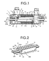
- Fig. 1 is a cross-sectional view of a cylinder type linear motor with a movable assembly of one embodiment of this invention.
- the cylinder type linear motor has a case 1, a stator 3, a movable assembly 5, and a linear sensor 7 to detect a position of the movable assembly 5.
- the case 1 has paired end brackets 11, 13 made of nonmagnetic material (e.g., aluminum). The end brackets 11, 13 are fixed to the ends of a stator core 15 of the stator 3 described later.
- the stator 3 has the cylinder type stator core 15 and a plurality of excitation windings 19.
- the stator core 15 is situated between the end brackets 11, 13.
- the stator core 15 has a yoke 21 and a plurality of magnetic poles 23 arranged at predetermined intervals in an axial direction of the movable assembly 5.
- the construction of the stator core 15 is well known and thus its explanation is omitted here.
- a linear sensor 7 having a hole sensor (a hole element) 8 can be used.
- grease-supplying paths 10, 12 through which grease can be supplied from outside to bearings 11a, 13a described below can be formed in paired end brackets 11, 13.
- the movable assembly 5 comprises two first and second direct drive shafts 27A, 27B, a movable core 29 formed of a laminated yoke fixed to the direct drive shafts 27A, 27B, and a plurality of permanent magnets 31 fixed to the movable core 29.
- the direct drive shafts 27A, 27B are shown shorter than their actual lengths.
- the direct drive shafts 27A, 27B are arranged parallel to each other and have the same shapes and dimensions.
- each of the direct drive shafts 27A, 27B has a yoke mounting portion 27a and paired supported portions 27b at both axial ends of the yoke mounting portion 27a.
- the yoke mounting portion 27a is cylindrically formed and fixed with the movable core.
- the paired supported portions 27b are formed in a cylindrical shape concentric with the yoke mounting portion 27a and, as shown in Fig. 1 , are supported by bearings 11a, 13a in the paired end brackets 11, 13 so that they can perform a linear reciprocal motion.
- the yoke mounting portion 27a of each of the first and second direct drive shafts 27A, 27B has a smaller cross section taken along a lateral line perpendicular to the axial direction than that of the supported portions 27b.
- the first and second direct drive shafts 27A, 27B are formed of a magnetic member whose magnetic resistance is smaller than a magnetic resistance of the laminated yoke 29 in a direction of lamination and which forms a magnetic path extending through the laminated yoke 29 in the direction of lamination (simply referred to as a magnetic path forming member). More specifically, the direct drive shafts 27A, 27B (magnetic path forming member) are formed of carbon steel.
- the laminated yoke 29 has a quadrangular prism structure whose cross section taken along a line perpendicular to the first and second direct drive shafts 27A, 27B is non-circular (in this example, rectangular).
- the laminated yoke 29 is formed by laminating a plurality of rectangular electromagnetic steel plates 33 in an axial direction of the first and second direct drive shafts 27A, 27B. As described later, a single, or a layer of, electromagnetic steel plate 33 is constructed of two divided electromagnetic steel plate pieces.
- the laminated yoke 29 is formed with two through-holes 35, 35 near the center through which the first and second direct drive shafts 27A, 27B are inserted.
- These two through-holes 35, 35 are arranged parallel to paired longer sides of the rectangular shape of the electromagnetic steel plates.
- outer circumferential surfaces 30A-30D of the laminated yoke 29 paired outer surfaces 30A, 30C extending parallel to the axial direction and opposing each other construct permanent magnet mounting surfaces on which a plurality of permanent magnets 31 are placed.
- the permanent magnets 31 are each shaped almost in a cuboid.
- the permanent magnets 31 are arranged to oppose the magnetic poles 23 of the stator 3, with their longitudinal direction set perpendicular to the axial direction of the first and second direct drive shafts 27A, 27B.
- the permanent magnets 31 are so arranged that any two adjacent permanent magnets 31 on the same surface of the laminated yoke 29 have different polarities on their outer surfaces and that any two opposing permanent magnets 31 on the top and bottom surfaces of the laminated yoke 29 that oppose each other through the laminated yoke 29 have different polarities on their outer surfaces.
- each of the electromagnetic steel plates 33 is constructed of first and second divided electromagnetic steel plate pieces 61A, 61B of the same shape.
- the shapes of the first and second divided electromagnetic steel plate pieces 61A, 61B are so determined that, when combined together to enclose the first and second direct drive shafts 27A, 27B, they can form the electromagnetic steel plate 33 that constitutes one of the layers of the laminated yoke 29.
- the first divided electromagnetic steel plate piece 61A has a contour including first and second shaft contact portions 61a, 61b, that are in contact with an outer circumferential surface of the yoke mounting portion 27a of the first direct drive shaft 27A and an outer circumferential surface of the yoke mounting portion 27a of the second direct drive shaft 27B respectively, and a connecting portion 61c connecting the first and second shaft contact portions 61a, 61b.
- the second divided electromagnetic steel plate piece 61B as with the first divided electromagnetic steel plate piece 61A, also has a contour including first and second shaft contact portions 61a, 61b, which are in contact with an outer circumferential surface of the yoke mounting portion 27a of the second direct drive shaft 27B and an outer circumferential surface of the yoke mounting portion 27a of the first direct drive shaft 27A, and a connecting portion 61c connecting the first and second shaft contact portions 61a, 61b.
- the first and second divided electromagnetic steel plate pieces 61A, 61B are pushed in directions of arrows A1, A2, respectively.
- the first and second direct drive shafts 27A, 27B are surrounded by the first divided electromagnetic steel plate piece 61A and the second divided electromagnetic steel plate piece 61B, with the first direct drive shaft 27A held between the first shaft contact portion 61a of the first electromagnetic steel plate piece 61A and the second shaft contact portion 61b of the second divided electromagnetic steel plate piece 61B and with the second direct drive shaft 27B held between the second shaft contact portion 61b of the first divided electromagnetic steel plate piece 61A and the first shaft contact portion 61a of the second divided electromagnetic steel plate piece 61B.
- the connecting portion 61c of the first divided electromagnetic steel plate piece 61A abuts the connecting portion 61c of the second divided electromagnetic steel plate piece 61B.
- the connecting portions 61c of the first and second divided electromagnetic steel plate pieces 61A, 61B incline at less than 45 degrees to an virtual line L1 connecting the centers of the first and second direct drive shafts 27A, 27B.
- first and second divided electromagnetic steel plate pieces 61A, 61B each has a contour including an engaging portion 61d and an engaged portion 61e.
- the engaging portion 61d is provided on one side of the connecting portion 61c where the first shaft contact portion 61a is situated.
- the engaged portion 61e is provided on the other side of the connecting portion 61c where the second shaft contact portion 61b is situated.
- the engaging portion 61d of the first divided electromagnetic steel plate piece 61A fits into the engaged portion 61e of the second divided electromagnetic steel plate piece 61B and the engaging portion 61d of the second divided electromagnetic steel plate piece 61B fits into the engaged portion 61e of the first divided electromagnetic steel plate piece 61A.
- This engagement structure prevents the combined state of the first and second divided electromagnetic steel plate pieces 61A, 61B from being disturbed easily.
- the two direct drive shafts 27A, 27B each have a smaller magnetic resistance than that of the laminated yoke 29 in the direction of lamination and form a magnetic path completely extending through the laminated yoke 29 in the direction of lamination.
- This arrangement can reduce an increase in the magnetic resistance of the movable core in the lamination direction.
- the movable core is constructed of the laminated yoke 29, which is formed by laminating the electromagnetic steel plates 33 in the axial direction, the magnetic characteristic of the movable core can be prevented from deteriorating significantly compared to those of the conventional movable core.
- a plurality of electromagnetic steel plates 33 can be precisely positioned with respect to the shafts 27A, 27B and also be prevented from rotating relative to the shafts 27A, 27B.
- first and second direct drive shafts 27A, 27B are so shaped that their yoke mounting portions 27a have smaller cross sections in the direction orthogonal to the axial direction than those of their supported portions 27b. This can reduce the cross section of the laminated yoke 29, making the laminated yoke more compactly and lighter than the conventional one. Since the outer circumferential surfaces of the first and second direct drive shafts 27A, 27B are enclosed by the first and second divided electromagnetic steel plate pieces 61A, 61B, the laminated yoke 29 can be fixed firmly to the yoke mounting portions 27a if the cross sections of the yoke mounting portions 27a of the first and second direct drive shafts 27A, 27B are made small.
- a plurality of the first divided electromagnetic steel plate pieces 61A are stacked and held together to form a first laminated yoke piece and a plurality of the second divided electromagnetic steel plate pieces 61B are laminated and held to form a second divided yoke piece.
- the first and second divided yoke pieces are combined to form the laminated yoke 29.
- a plurality of permanent magnets 31 on one of the paired side surfaces are arranged in such a manner that polarity appearing on an outer surface of one of the permanent magnets 31 is different from that of the other permanent magnets adjacent to the one of the permanent magnets, and is also different from that of its opposing permanent magnet on the other side of the paired side surfaces.
- step portions between the yoke mounting portion 27a and the pair of supported portions 27b are each formed by a ring-shaped surface 27c orthogonal to the axes of the shafts.
- the step portions between the yoke mounting portion 27a and the paired supported portions 27b can take a variety of forms. For example, in a direct drive shaft 127A(B) shown in Fig.
- step portions between a yoke mounting portion 127a and paired supported portions 127b are formed by an inclining surface 127c that inclines away from the axis of the direct drive shaft 127A(B) from the yoke mounting portion 127a toward the paired supported portions 127b.
- the first and second divided electromagnetic steel plate pieces that together form a single electromagnetic steel plate can also take a variety of shapes.
- An electromagnetic steel plate 133 shown in Fig. 6 is also constructed of first and second divided electromagnetic steel plate pieces 161A, 161B in the same shape.
- a connecting portion 161c of the first divided electromagnetic steel plate piece 161A has a tangent portion 161f extending from an end of a first shaft contact portion 161a along a line tangent to a first direct drive shaft 127A and an abutment portion 161g extending along a line connecting the centers of the first and second direct drive shafts 127A, 127B.
- a connecting portion 161c of the second divided electromagnetic steel plate piece 161B similarly has a tangent portion 161f extending from an end of the first shaft contact portion 161a along a line tangent to the second direct drive shaft 127B and an abutment portion 161g extending along a line connecting the centers of the first and second direct drive shafts 127A, 127B.
- the first and second divided electromagnetic steel plate pieces 161A, 161B are so shaped that, when combined together to enclose the first and second direct drive shafts 127A, 127B, the steel plate pieces 161A, 161B are each formed with an insertion hole 162 at the abutment portion 161g.
- this insertion hole 162 an insertion member 128 is inserted parallel to the first and second direct drive shafts 127A, 127B.
- the insertion member 128 is shaped like a letter H in a cross section orthogonal to the axes of the first and second direct drive shafts 127A, 127B.
- the use of the electromagnetic steel plate 133 of this example can keep the combined state of the first and second divided electromagnetic steel plate pieces 161A, 161B by the insertion member 128, so there is no need for these steel plate pieces to have the engaging portion and the engaged portion at their periphery.
- An electromagnetic steel plate 233 shown in Fig. 7 is constructed of first and second divided electromagnetic steel plate pieces 261A, 261B in the same shape.
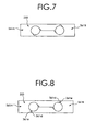
- the electromagnetic steel plate 233 of this example is similar in construction to the electromagnetic steel plate 133 of Fig. 6 , except that it has no insertion hole.
- An electromagnetic steel plate 333 shown in Fig. 8 is constructed of first and second divided electromagnetic steel plate pieces 361A, 361B in the same shape.
- the first and second electromagnetic steel plate pieces 361A, 361B each have an engaging portion 361d and an engaged portion 361e at their contour.
- the engaging portion 361d of the first divided electromagnetic steel plate piece 361A is provided in the form of a projection protruding toward the second divided electromagnetic steel plate piece 361B.
- the engaging portion 361d of the second divided electromagnetic steel plate piece 361B is provided in the form of a projection protruding toward the first divided electromagnetic steel plate piece 361A.
- the engaged portion 361e of the first divided electromagnetic steel plate piece 361A is recessed relative to the second divided electromagnetic steel plate piece 361B and provided in the form of a recess into which the engaging portion 361d of the second divided electromagnetic steel plate piece 361B is fitted.
- the engaged portion 361e of the second divided electromagnetic steel plate piece 361B is recessed relative to the first divided electromagnetic steel plate piece 361A and is provided in the form of a recess into which the engaging portion 361d of the first divided electromagnetic steel plate piece 361A is fitted.
- An electromagnetic steel plate 433 shown in Fig. 9 is constructed of first and second divided electromagnetic steel plate pieces 461A, 461B in the same shape.
- the first and second divided electromagnetic steel plate pieces 461A, 461B each have a contour including an engaging portion 461d and an engaged portion 461e, as with the electromagnetic steel plate 333 in Fig. 8 .
- a connecting portion 461c of the first and second divided electromagnetic steel plate pieces 461A, 461B has three linear portions 461h-461j extending between the first direct drive shaft 27A and the second direct drive shaft 27B, a linear portion 461k extending in a direction orthogonal to the linear portions 461h-461j and connecting the linear portion 461h and the linear portion 461i, and a linear portion 461m extending in a direction orthogonal to the linear portions 461h-461j and connecting the linear portion 461i and the linear portion 461j.
- the linear portion 461h of the first divided electromagnetic steel plate piece 461A abuts the linear portion 461j of the second divided electromagnetic steel plate piece 461B; the linear portion 461i of the first divided electromagnetic steel plate piece 461A abuts the linear portion 461i of the second divided electromagnetic steel plate piece 461B; the linear portion 461j of the first divided electromagnetic steel plate piece 461A abuts the linear portion 461h of the second divided electromagnetic steel plate piece 461B; the linear portion 461k of the first divided electromagnetic steel plate piece 461A abuts the linear portion 461m of the second divided electromagnetic steel plate piece 461B; and the linear portion 461m of the first divided electromagnetic steel plate piece 461A abuts the linear portion 461k of the second divided electromagnetic steel plate piece 461B.
- the connecting portions 461c of the first and second divided electromagnetic steel plate pieces 461A, 461B form engaging step portions through which the first divided electromagnetic steel plate piece 461A and the second divided electromagnetic steel plate piece 461B are firmly connected.
- An electromagnetic steel plate 533 shown in Fig. 10 is constructed of first and second divided electromagnetic steel plate pieces 561A, 561B in the same shape.
- yoke mounting portions 527a of the first and second direct drive shafts 527A, 527B are formed in a shape similar to a rectangle or in a noncircular shape at cross section. More specifically, the cross section of the yoke mounting portions 527a has two parallel sides 527d, 527e and two curved sides 527f, 527g, which are outwardly convex and connect ends of the parallel sides 527d, 527e.
- a first shaft contact portion 561a at the contour of the first divided electromagnetic steel plate piece 561A abuts the side 527d, a half of the side 527e, the curved side 527f and a half of the curved side 527g of the first direct drive shaft 527A.
- a second shaft contact portion 561b at the contour of the first divided electromagnetic steel plate piece 561A abuts a half of the side 527e and a half of the curved side 527g of the second direct drive shaft 527B.
- a first shaft contact portion 561a at the periphery of the second divided electromagnetic steel plate piece 561B abuts the side 527d, a half of the side 527e, the curved side 527f and a half of the curved side 527g of the second direct drive shaft 527B.
- a second shaft contact portion 561b at the periphery of the second divided electromagnetic steel plate piece 561B abuts a half of the side 527e and a half of the curved side 527g of the first direct drive shaft 527A.
- a connecting portion 561c of each of the first and second divided electromagnetic steel plate pieces 561A, 561B extend along a line connecting the centers of the first and second direct drive shafts 527A, 527B.
- each of the connecting portions 561c has a contour including an engaging portion 561d and an engaged portion 561e.
- the engaging portion 561d of the first divided electromagnetic steel plate piece 561A is formed of a projection protruding toward the second divided electromagnetic steel plate piece 561B and the engaging portion 561d of the second divided electromagnetic steel plate piece 561B is formed of a projection protruding toward the first divided electromagnetic steel plate piece 561A.
- the engaged portion 561e of the first divided electromagnetic steel plate piece 561A is recessed relative to the second divided electromagnetic steel plate piece 561B and provided in the form of a recess into which the engaging portion 561d of the second divided electromagnetic steel plate piece 561B is fitted.
- the engaged portion 561e of the second divided electromagnetic steel plate piece 561B is recessed relative to the first divided electromagnetic steel plate piece 561A and provided in the form of a recess into which the engaging portion 561d of the first divided electromagnetic steel plate piece 561A is fitted.
- the movable assembly can adopt a variety of constructions.
- a laminated yoke 629 of a movable assembly 605 in Fig. 11 has a quadrangular square-columnar structure whose cross section in to the direction orthogonal to the direct drive shafts 627A, 627B in the laminated yoke 629 is almost square.
- a plurality of square electromagnetic steel plates 633 are laminated in an axial direction of the direct drive shafts 627A, 627B to form the laminated yoke 629.
- the laminated yoke 629 has on its outer circumference four rectangular permanent magnet mounting surfaces 630A-630D extending parallel to the direct drive shafts 627A, 627B on which a plurality of permanent magnets 631 are mounted. In this example, any four circumferentially aligned permanent magnets 631 mounted one on each of the four permanent magnet mounting surfaces 630A-630D are so arranged that they have the same polarities on their outer surfaces.
- the four circumferentially aligned permanent magnets 631 mounted one on each of the four permanent magnet mounting surfaces 630A-630D may be arranged so that their polarity on their outer surface changes alternately.
- the plurality of permanent magnets 631 thereon are juxtaposed in the axial direction of the direct drive shafts 627 in such a manner that polarity, N or S, appears alternatively in the axial direction.
- the polarity pattern of the permanent magnets 631 on the permanent magnet mounting surface 630A is the same as the polarity pattern of the permanent magnets 631 on the permanent magnet mounting surface 630B.
- the polarity pattern of permanent magnet 631 on the permanent magnet mounting surface 630C is the same as the polarity pattern of the permanent magnets 631 on the permanent magnet mounting surface 630D.
- the polarity pattern of the permanent magnets 631 on the permanent magnet mounting surfaces 630A, 630B is the opposite pattern from that on the permanent magnet mounting surfaces 630C, 630D.
- the polarity appearing on an outer surface of one of the permanent magnets on one of the paired side surface is different from that of the opposing permanent magnets on the other of the paired side surfaces.
- a laminated yoke 729 of a movable assembly 705 shown in Fig. 14(a) is constructed of a plurality of electromagnetic steel plates 733, each of which is formed with four through-holes. These through-holes constitute four permanent magnet receiving holes 737 formed in the laminated yoke 729.
- the four permanent magnet receiving holes 737 are formed at peripheral portions of the laminated yoke 729 along its circumferential surface.
- Each of the four permanent magnet receiving holes 737 receives a plate-like permanent magnet group 739.
- the permanent magnet group 739 comprises a plurality of permanent magnets 731 arranged so that their polarity on the outer surface alternates. They are arranged parallel to each other and joined together, with a spacer 741 of nonmagnetic material interposed between the adjacent permanent magnets.
- Figs. 14(b) to 14(d) show permanent magnet groups whose constructions differ from that of the permanent magnet group of the movable assembly shown in Fig. 14(a) .
- a permanent magnet group 2139 of Fig. 14(b) uses no spacer and, in other respects, has the similar construction to that of the permanent magnet group 739 of Fig. 14(a) .
- a permanent magnet group 3139 shown in Fig. 14(c) has an integrally formed plate of magnetic material magnetized so that N pole and S pole appear alternately on its surface.
- a permanent magnet group 4139 shown in Fig. 14(d) has an integrally formed plate of magnetic material magnetized so that a plurality of permanent magnet portions 4131 and spacer portions 4141 are alternated.
- the spacer portions 4141 are magnetized so that their magnetization direction is rotated 90 degrees from those of the adjacent permanent magnet portions 4131 to form a magnetic path along the polarities of the adjacent permanent magnet portions 4131. That is, the permanent magnet group 4139 is constructed in a so-called Halbach magnet array.
- the permanent magnet group 4139 may be pre-magnetized before being fixed to the laminated yoke or may be formed by one fixing a permanent magnetic material to the laminated yoke and then magnetizing it.
- a movable assembly 805 shown in Fig. 15 has a single direct drive shaft 827.
- the movable assembly 805 of this example as with the one shown in Fig. 11 , also has the direct drive shaft 827 constructed of a magnetic path forming material.
- electromagnetic steel plates 833 are each shaped like a circular plate so that a laminated yoke 829 is constructed in a shape of a circular column.
- a movable assembly 905 shown in Fig. 16 has one direct drive shaft 927.
- the shaft is formed of a nonmagnetic or weak magnetic SUS material.
- a laminated yoke 929 is cylindrically formed. Though not shown in Fig. 16 , the laminated yoke 929 has a plurality of annular permanent magnets fixed thereto.
- the laminated yoke 929 is constructed of a plurality of ring-shaped electromagnetic steel plates 933 laminated. In this example, a cylindrical portion 943 of a magnetic path forming material is arranged between the laminated yoke 929 and the direct drive shaft 927.
- the cylindrical portion 943 is formed in an elongate cylindrical shape and receives the direct drive shaft 927 through its center hole 943a.
- the cylindrical portion 943 has a magnetic resistance smaller than that of the laminated yoke 929 in the lamination direction and forms a magnetic path extending through the laminated yoke 929 in the lamination direction. Further, the cylindrical portion 943 can increase the strength of the laminated yoke 929.
- a movable assembly 1005 shown in Fig. 17(a) has one direct drive shaft 1027.
- the shaft is formed of a nonmagnetic or weak magnetic SUS material.
- a laminated yoke 1029 is cylindrically formed. Though not shown in this example, the laminated yoke 1029 also has a plurality of annular permanent magnets fixed thereto.
- the laminated yoke 1029 is constructed of a plurality of ring-shaped electromagnetic steel plates 1033 laminated.
- a cylindrical structure 1043 made of a magnetic path forming material is arranged between the laminated yoke 1029 and the direct drive shaft 1027. The cylindrical structure 1043, as shown in Fig.
- the cylindrical portion 1043a is shaped like an elongate cylinder.
- the flange portion 1043b is formed like a short cylinder, shorter in length and larger in diameter than the cylindrical portion 1043a, and is provided at one end of the cylindrical portion 1043a.
- the direct drive shaft 1027 extends through a center hole 1043c of the cylindrical portion 1043a and the flange portion 1043b. Thus, the flange portion 1043b abuts one end face of the laminated yoke 1029 in the lamination direction.
- the cylindrical structure 1043 has a smaller magnetic resistance than that of the laminated yoke 1029 in the lamination direction and forms a magnetic path extending through the laminated yoke 1029 in the lamination direction. Further, the flange portion 1043b prevents the laminated yoke 1029 from directly contacting a case of a cylinder type linear motor, thereby protecting the movable assembly 1005 against possible damages.
- a movable assembly 1105 shown in Fig. 18 has one direct drive shaft 1127.
- the shaft is formed of a nonmagnetic or weak magnetic SUS material.
- a laminated yoke 1129 is shaped in a square column. Though not shown in this example, the laminated yoke 1129 also has a plurality of permanent magnets arranged on four permanent magnet mounting surfaces 1130A-1130D.
- the laminated yoke 1129 is constructed of a plurality of almost square electromagnetic steel plates 1133 laminated. In this example, the laminated yoke 1129 is formed therein with four magnet receiving holes 1145A-1145D extending along the direct drive shaft 1127 which correspond to the four permanent magnet mounting surfaces 1130A-1130D.
- the four magnet receiving holes 1145A-1145D form rectangular prism-structured inner spaces in which plate-like divided magnets 1143A-1143D made of a magnetic path forming material are fitted.
- the divided magnets 1143A-1143D form a magnetic path extending in the lamination direction of the laminated yoke 1129 and which has a smaller magnetic resistance than that of the laminated yoke 1129 in the lamination direction.
- the plate-like divided magnets 1143A-1143D can enhance the positioning precision of the electromagnetic steel plates 1133 relative to the direct drive shaft 1127 and also increase their mechanical strength.
- a movable assembly 1205 shown in Fig. 19 has two direct drive shafts 1227 formed of a magnetic path forming material.
- a laminated yoke 1229 of this movable assembly 1205 is constructed of a plurality of electromagnetic steel plates 1233, each of which has four through-holes. These through-holes form four permanent magnet receiving holes 1237 in the laminated yoke 1229.
- the four permanent magnet receiving holes 1237 are formed in a peripheral portions of the laminated yoke 1229 along its outer circumferential surface.
- In these four permanent magnet receiving holes 1237 are fitted plate-like permanent magnet groups 1239, each of which has a plurality of permanent magnets 1231 arranged parallel to each other and joined so that a magnetic polarity on their outer surface alternates between N and S poles.
- the laminated yoke 1229 has an angle base 1251 fixed to one end face, in the lamination direction, of the laminated yoke 1229.
- One of the outer circumferential surfaces of the laminated yoke is formed with a groove 1253 that extends in the lamination direction of the electromagnetic steel plates 1233.
- a position detection linear scale 1252 is fixed to both the groove 1253 and the angle base 1251.
- the position detection linear scale 1252 is an elongate metal strip used to detect a position of the movable assembly with respect to the stator and formed with a number of parallel notches extending in a direction orthogonal to the longitudinal direction of the metal strip.
- An optical reader mounted on the stator reads the scale to determine the position of the movable assembly.
- the groove 1253 is about 0.2 mm deep and has almost no effect on a thrusting force. Since the groove 1253 is formed at the same time that the electromagnetic steel plates 1233 are stamped, the movable assembly can be manufactured at low cost, with enhanced mechanical precision. This arrangement can also enhance the precision of the position at which the position detection linear scale 1252 is fixed.
- a movable assembly 1305 shown in Fig. 20 has two direct drive shafts 1227 formed of a magnetic path forming material.
- a laminated yoke 1329 of this movable assembly 1305 is constructed of a plurality of electromagnetic steel plates 1333, each of which has two permanent magnet mounting surfaces 1330A, 1330B on which permanent magnets 1331 are fixed.
- a groove 1353 extending in the lamination direction of the electromagnetic steel plates 1333 is formed.
- the groove 1353 is rigidly attached with a position detection linear scale 1352. This construction enables the linear scale to be fixed with high precision without increasing the number of parts and makes for a reduction in space.
Landscapes
- Engineering & Computer Science (AREA)
- Power Engineering (AREA)
- Physics & Mathematics (AREA)
- Chemical & Material Sciences (AREA)
- Combustion & Propulsion (AREA)
- Electromagnetism (AREA)
- Linear Motors (AREA)
- Iron Core Of Rotating Electric Machines (AREA)
- Reciprocating, Oscillating Or Vibrating Motors (AREA)
Priority Applications (1)
| Application Number | Priority Date | Filing Date | Title |
|---|---|---|---|
| EP09167640.3A EP2124321B1 (en) | 2003-08-27 | 2004-08-27 | Moveable assembly for cylinder type linear motor |
Applications Claiming Priority (4)
| Application Number | Priority Date | Filing Date | Title |
|---|---|---|---|
| JP2003303027 | 2003-08-27 | ||
| JP2003303027 | 2003-08-27 | ||
| JP2004242594A JP4603316B2 (ja) | 2003-08-27 | 2004-08-23 | シリンダ型リニアモータ用可動子 |
| JP2004242594 | 2004-08-23 |
Related Child Applications (2)
| Application Number | Title | Priority Date | Filing Date |
|---|---|---|---|
| EP09167640.3A Division EP2124321B1 (en) | 2003-08-27 | 2004-08-27 | Moveable assembly for cylinder type linear motor |
| EP09167640.3 Division-Into | 2009-08-11 |
Publications (3)
| Publication Number | Publication Date |
|---|---|
| EP1511163A2 EP1511163A2 (en) | 2005-03-02 |
| EP1511163A3 EP1511163A3 (en) | 2007-05-02 |
| EP1511163B1 true EP1511163B1 (en) | 2010-06-30 |
Family
ID=34106952
Family Applications (2)
| Application Number | Title | Priority Date | Filing Date |
|---|---|---|---|
| EP04255212A Expired - Lifetime EP1511163B1 (en) | 2003-08-27 | 2004-08-27 | Movable assembly for cylinder type linear motor |
| EP09167640.3A Expired - Lifetime EP2124321B1 (en) | 2003-08-27 | 2004-08-27 | Moveable assembly for cylinder type linear motor |
Family Applications After (1)
| Application Number | Title | Priority Date | Filing Date |
|---|---|---|---|
| EP09167640.3A Expired - Lifetime EP2124321B1 (en) | 2003-08-27 | 2004-08-27 | Moveable assembly for cylinder type linear motor |
Country Status (7)
| Country | Link |
|---|---|
| US (2) | US7276820B2 (https=) |
| EP (2) | EP1511163B1 (https=) |
| JP (1) | JP4603316B2 (https=) |
| KR (1) | KR101062710B1 (https=) |
| CN (2) | CN100550582C (https=) |
| DE (1) | DE602004027872D1 (https=) |
| TW (1) | TW200511690A (https=) |
Families Citing this family (41)
| Publication number | Priority date | Publication date | Assignee | Title |
|---|---|---|---|---|
| KR100552586B1 (ko) * | 2004-05-21 | 2006-02-20 | 삼성광주전자 주식회사 | 리니어 모터 및 이를 갖춘 리니어 압축기 |
| JP5107922B2 (ja) * | 2005-08-16 | 2012-12-26 | コーニンクレッカ フィリップス エレクトロニクス エヌ ヴィ | プログラマブル作動機能を有するパーソナルケア装置に対する共振アクチュエータ |
| US20070058188A1 (en) * | 2005-09-14 | 2007-03-15 | Kabushiki Kaisha Toshiba | Image forming apparatus, image forming method, and image forming program |
| DE102005057370B4 (de) * | 2005-12-01 | 2011-12-29 | Siemens Ag | Rotationslinearantriebsanordnung |
| JP5194472B2 (ja) * | 2007-02-09 | 2013-05-08 | 株式会社ジェイテクト | リニアモータおよびそれを備えた工具移動装置 |
| US20090148319A1 (en) * | 2007-12-05 | 2009-06-11 | Industrial Technology Research Institute | Linear compressor with permanent magnets |
| JP5415161B2 (ja) * | 2008-08-08 | 2014-02-12 | 山洋電気株式会社 | リニア同期モータ |
| US7965010B2 (en) * | 2008-09-03 | 2011-06-21 | Bose Corporation | Linear motor with patterned magnet arrays |
| JP5606049B2 (ja) * | 2008-12-11 | 2014-10-15 | 山洋電気株式会社 | リニア同期モータ |
| TWI460966B (zh) | 2009-01-23 | 2014-11-11 | Hitachi Metals Ltd | Moving elements and linear motors |
| KR101046754B1 (ko) * | 2009-05-13 | 2011-07-06 | 주식회사 효성 | 리니어 기기의 이동자 |
| JP2011217535A (ja) * | 2010-03-31 | 2011-10-27 | Sinfonia Technology Co Ltd | リニア駆動装置の可動子及びリニア駆動装置 |
| JP5764929B2 (ja) * | 2010-04-14 | 2015-08-19 | 株式会社安川電機 | 直動回転アクチュエータ |
| US9325232B1 (en) | 2010-07-22 | 2016-04-26 | Linear Labs, Inc. | Method and apparatus for power generation |
| JP5646250B2 (ja) * | 2010-08-18 | 2014-12-24 | Thk株式会社 | 磁界遮蔽機構、アクチュエータ |
| WO2012023565A1 (ja) * | 2010-08-18 | 2012-02-23 | Thk株式会社 | 磁界遮蔽機構、アクチュエータ |
| CN103250330B (zh) * | 2010-10-22 | 2016-09-14 | 弗雷德·E·汉斯德堡 | 一种改进的磁电机 |
| JP5874246B2 (ja) * | 2011-08-31 | 2016-03-02 | シンフォニアテクノロジー株式会社 | リニア駆動装置の可動子 |
| JP5953688B2 (ja) * | 2011-09-27 | 2016-07-20 | シンフォニアテクノロジー株式会社 | リニア駆動装置 |
| JP5356488B2 (ja) * | 2011-10-17 | 2013-12-04 | 山洋電気株式会社 | リニアモータ用可動子 |
| US10128732B2 (en) | 2012-02-20 | 2018-11-13 | Hitachi, Ltd. | Linear motor |
| US9270155B2 (en) | 2012-05-20 | 2016-02-23 | Mts Systems Corporation | Linear actuator assembly |
| WO2014036567A1 (en) | 2012-09-03 | 2014-03-06 | Linear Labs, Inc. | An improved transducer and method of operation |
| CN103337941A (zh) * | 2013-06-20 | 2013-10-02 | 同济大学 | 车用类管状永磁直线电机 |
| CA2831197A1 (en) * | 2013-10-28 | 2015-04-28 | Patrick Mcfadden | Electric linear actuator |
| CN104393737B (zh) * | 2014-11-24 | 2018-08-10 | 北京航空航天大学 | 直线振荡电机 |
| CN204425641U (zh) * | 2015-01-29 | 2015-06-24 | 瑞声科技(南京)有限公司 | 电磁扬声器 |
| RU2586116C1 (ru) * | 2015-05-19 | 2016-06-10 | Общество с ограниченной ответственностью "СПЕЦИАЛЬНАЯ СТРОИТЕЛЬНАЯ ТЕХНИКА" | Электродвигатель с возвратно-поступательным движением якоря |
| WO2017008085A1 (en) * | 2015-07-09 | 2017-01-12 | Linear Labs, Inc. | An improved electric linear motor/generator |
| CN105207441B (zh) * | 2015-09-23 | 2017-11-21 | 歌尔股份有限公司 | 线性振动马达 |
| CN105207440B (zh) | 2015-09-23 | 2017-11-21 | 歌尔股份有限公司 | 磁平衡导向线性振动马达 |
| CN106612046A (zh) * | 2015-10-23 | 2017-05-03 | 大银微系统股份有限公司 | 旋转及直线运动机构 |
| US10381144B1 (en) * | 2016-09-21 | 2019-08-13 | Apple Inc. | Haptic actuator with ferritic core |
| WO2018106910A1 (en) * | 2016-12-07 | 2018-06-14 | Mts Systems Corporation | Electric actuator |
| GB2558677A (en) * | 2017-02-06 | 2018-07-18 | Libertine Fpe Ltd | Linear electrical machine |
| DE102017215238A1 (de) * | 2017-08-31 | 2019-02-28 | Contitech Vibration Control Gmbh | Elektromagnetischer Linearaktor |
| RU2720882C1 (ru) * | 2019-09-04 | 2020-05-13 | Федеральное государственное бюджетное образовательное учреждение высшего образования "Омский государственный технический университет"(ОмГТУ) | Электротехнический комплекс поршневого компрессора на основе линейной магнитоэлектрической машины |
| KR102091358B1 (ko) * | 2019-09-10 | 2020-05-26 | 주식회사 케이메카트로닉스 | 리니어 모터 및 이를 적용한 로봇 장치 |
| JP7491138B2 (ja) * | 2020-08-21 | 2024-05-28 | 富士電機株式会社 | 永久磁石界磁、製造方法、リニアモータ |
| FI20215948A1 (en) * | 2021-09-09 | 2023-03-10 | Mirka Ltd | Method and apparatus for surface processing |
| WO2025209837A1 (en) * | 2024-04-04 | 2025-10-09 | Gea Mechanical Equipment Italia S.P.A. | A linear vernier machine |
Family Cites Families (23)
| Publication number | Priority date | Publication date | Assignee | Title |
|---|---|---|---|---|
| DE1513788A1 (de) * | 1966-01-08 | 1969-06-04 | Licentia Gmbh | Anordnung von geblechten Polen zu einem Polrad fuer Synchron-Innenpolgeneratoren |
| NL6702187A (https=) * | 1967-02-14 | 1968-08-15 | ||
| DE2541599A1 (de) | 1975-09-18 | 1977-03-24 | Weh Herbert | Integrierte magnetfahrtechnik fuer den nahverkehr |
| DE2938379A1 (de) | 1979-09-22 | 1981-04-09 | Herbert Prof. Dr.-Ing. 3300 Braunschweig Weh | Synchronmaschinen mit zweifacher erregung und wechselmagnetisierung fuer lineare und rotatorische anordnung |
| DE3243212A1 (de) * | 1982-11-23 | 1984-05-24 | SWF-Spezialfabrik für Autozubehör Gustav Rau GmbH, 7120 Bietigheim-Bissingen | Elektrischer kleinmotor mit einem anker |
| JPH0797898B2 (ja) * | 1986-05-22 | 1995-10-18 | 株式会社シコ−技研 | リニア磁気エンコ−ダを有するボイスコイル型リニア直流モ−タ |
| US5023495A (en) * | 1990-04-17 | 1991-06-11 | Hitachi Metals & Shicoh Engine | Moving-magnet type linear d.c. brushless motor having plural moving elements |
| JPH0522920A (ja) * | 1990-09-28 | 1993-01-29 | Aisin Seiki Co Ltd | リニアアクチユエータ |
| CN2077389U (zh) * | 1990-11-13 | 1991-05-22 | 青海工程机械厂 | 摆臂式自装卸车倾翻机构 |
| JP3125230B2 (ja) * | 1992-01-07 | 2001-01-15 | 株式会社シコー技研 | リニア直流モ−タ内へのリニア磁気エンコ−ダの組込み形成方法 |
| JPH073253U (ja) * | 1993-06-10 | 1995-01-17 | 株式会社三協精機製作所 | 回転電機の鉄心 |
| JPH07329783A (ja) * | 1994-06-15 | 1995-12-19 | East Japan Railway Co | リニア同期モータ駆動式電気転てつ機 |
| US5751076A (en) * | 1996-01-19 | 1998-05-12 | Inventio Ag | Drive system for lifts |
| CN2309014Y (zh) * | 1997-08-20 | 1999-02-24 | 张云龙 | 管式直线电机 |
| JPH11187639A (ja) * | 1997-12-19 | 1999-07-09 | Matsushita Electric Ind Co Ltd | 磁石可動型リニアアクチュエータ |
| JP3789671B2 (ja) | 1999-02-15 | 2006-06-28 | 三洋電機株式会社 | リニアモータの固定子およびその製造方法 |
| JP2001128434A (ja) * | 1999-10-27 | 2001-05-11 | Matsushita Refrig Co Ltd | リニアモータ |
| CN2418615Y (zh) * | 2000-04-21 | 2001-02-07 | 山东高密豪迈机械有限公司 | 直线电机 |
| JP3945148B2 (ja) * | 2000-11-02 | 2007-07-18 | 株式会社日立製作所 | Xyテーブル及びxyzテーブル |
| JP2002325421A (ja) * | 2001-02-23 | 2002-11-08 | Canon Inc | リニアモータ、およびこれを用いたステージ装置、露光装置ならびにデバイス製造方法 |
| JP3717436B2 (ja) * | 2001-03-30 | 2005-11-16 | 山洋電気株式会社 | シリンダ型リニア同期モータ |
| JP3993073B2 (ja) * | 2001-12-11 | 2007-10-17 | アスモ株式会社 | 回転電機の回転子及びその製造方法 |
| JP2004064852A (ja) * | 2002-07-26 | 2004-02-26 | Matsushita Refrig Co Ltd | リニアモータ及びリニアモータコンプレッサ |
-
2004
- 2004-08-23 JP JP2004242594A patent/JP4603316B2/ja not_active Expired - Fee Related
- 2004-08-26 TW TW093125552A patent/TW200511690A/zh not_active IP Right Cessation
- 2004-08-26 US US10/926,685 patent/US7276820B2/en not_active Expired - Fee Related
- 2004-08-27 DE DE602004027872T patent/DE602004027872D1/de not_active Expired - Lifetime
- 2004-08-27 KR KR1020040068085A patent/KR101062710B1/ko not_active Expired - Fee Related
- 2004-08-27 CN CNB2004100682929A patent/CN100550582C/zh not_active Expired - Fee Related
- 2004-08-27 EP EP04255212A patent/EP1511163B1/en not_active Expired - Lifetime
- 2004-08-27 EP EP09167640.3A patent/EP2124321B1/en not_active Expired - Lifetime
- 2004-08-27 CN CN2009101463616A patent/CN101640468B/zh not_active Expired - Fee Related
-
2007
- 2007-08-27 US US11/845,474 patent/US7501724B2/en not_active Expired - Fee Related
Also Published As
| Publication number | Publication date |
|---|---|
| CN101640468B (zh) | 2012-11-28 |
| KR101062710B1 (ko) | 2011-09-08 |
| EP2124321B1 (en) | 2013-07-03 |
| US7501724B2 (en) | 2009-03-10 |
| CN1592049A (zh) | 2005-03-09 |
| KR20050021939A (ko) | 2005-03-07 |
| CN101640468A (zh) | 2010-02-03 |
| US7276820B2 (en) | 2007-10-02 |
| JP2005102486A (ja) | 2005-04-14 |
| TW200511690A (en) | 2005-03-16 |
| TWI331836B (https=) | 2010-10-11 |
| EP1511163A2 (en) | 2005-03-02 |
| EP2124321A1 (en) | 2009-11-25 |
| CN100550582C (zh) | 2009-10-14 |
| US20050046282A1 (en) | 2005-03-03 |
| US20070296282A1 (en) | 2007-12-27 |
| EP1511163A3 (en) | 2007-05-02 |
| DE602004027872D1 (de) | 2010-08-12 |
| JP4603316B2 (ja) | 2010-12-22 |
Similar Documents
| Publication | Publication Date | Title |
|---|---|---|
| EP1511163B1 (en) | Movable assembly for cylinder type linear motor | |
| JP4687871B2 (ja) | アキシャルギャップ型電動機 | |
| KR101531736B1 (ko) | 직동 회전 엑츄에이터 | |
| US10399122B2 (en) | Vibration motor | |
| US20130207507A1 (en) | Rotor assembly for motor and manufacturing method thereof | |
| JP2009201269A (ja) | 埋込磁石モータおよびその製造方法 | |
| WO2009081766A1 (ja) | 電動機および回転電機用ロータ | |
| JPS63257448A (ja) | 電子的に整流されるコレクタのない直流モータ | |
| JP4286642B2 (ja) | 永久磁石式回転子 | |
| JP2009195055A (ja) | 回転電機 | |
| WO2019116389A1 (en) | Unitary stator, slit rotor and a switched reluctance device thereof | |
| CN112583154A (zh) | 转子和马达 | |
| CN118235313B (zh) | 同步磁阻电动机的转子 | |
| JP5554913B2 (ja) | リニアアクチュエータ | |
| JPH09275652A (ja) | Dcブラシレス用モータのロータ | |
| JP2010017028A (ja) | 回転電機用ロータおよび電動機 | |
| JP2007318859A (ja) | アクチュエータ | |
| JP4801824B2 (ja) | 磁気機械 | |
| JP7688142B2 (ja) | ロータおよびモータ | |
| JP2010017031A (ja) | 回転電機用ロータ | |
| JP2010017030A (ja) | 回転電機用ロータおよび電動機 | |
| JP4648378B2 (ja) | 電動機 | |
| JP2010017029A (ja) | 回転電機用ロータおよび電動機 | |
| JP2010017027A (ja) | 回転電機用ロータ | |
| JP2015142439A (ja) | 希土類磁石モータ |
Legal Events
| Date | Code | Title | Description |
|---|---|---|---|
| PUAI | Public reference made under article 153(3) epc to a published international application that has entered the european phase |
Free format text: ORIGINAL CODE: 0009012 |
|
| AK | Designated contracting states |
Kind code of ref document: A2 Designated state(s): AT BE BG CH CY CZ DE DK EE ES FI FR GB GR HU IE IT LI LU MC NL PL PT RO SE SI SK TR |
|
| AX | Request for extension of the european patent |
Extension state: AL HR LT LV MK |
|
| PUAL | Search report despatched |
Free format text: ORIGINAL CODE: 0009013 |
|
| AK | Designated contracting states |
Kind code of ref document: A3 Designated state(s): AT BE BG CH CY CZ DE DK EE ES FI FR GB GR HU IE IT LI LU MC NL PL PT RO SE SI SK TR |
|
| AX | Request for extension of the european patent |
Extension state: AL HR LT LV MK |
|
| 17P | Request for examination filed |
Effective date: 20071005 |
|
| AKX | Designation fees paid |
Designated state(s): DE FR GB |
|
| 17Q | First examination report despatched |
Effective date: 20090304 |
|
| GRAP | Despatch of communication of intention to grant a patent |
Free format text: ORIGINAL CODE: EPIDOSNIGR1 |
|
| GRAS | Grant fee paid |
Free format text: ORIGINAL CODE: EPIDOSNIGR3 |
|
| GRAA | (expected) grant |
Free format text: ORIGINAL CODE: 0009210 |
|
| AK | Designated contracting states |
Kind code of ref document: B1 Designated state(s): DE FR GB |
|
| REG | Reference to a national code |
Ref country code: GB Ref legal event code: FG4D |
|
| REF | Corresponds to: |
Ref document number: 602004027872 Country of ref document: DE Date of ref document: 20100812 Kind code of ref document: P |
|
| PLBE | No opposition filed within time limit |
Free format text: ORIGINAL CODE: 0009261 |
|
| STAA | Information on the status of an ep patent application or granted ep patent |
Free format text: STATUS: NO OPPOSITION FILED WITHIN TIME LIMIT |
|
| 26N | No opposition filed |
Effective date: 20110331 |
|
| REG | Reference to a national code |
Ref country code: DE Ref legal event code: R097 Ref document number: 602004027872 Country of ref document: DE Effective date: 20110330 |
|
| PGFP | Annual fee paid to national office [announced via postgrant information from national office to epo] |
Ref country code: DE Payment date: 20140821 Year of fee payment: 11 |
|
| PGFP | Annual fee paid to national office [announced via postgrant information from national office to epo] |
Ref country code: FR Payment date: 20140821 Year of fee payment: 11 Ref country code: GB Payment date: 20140820 Year of fee payment: 11 |
|
| REG | Reference to a national code |
Ref country code: DE Ref legal event code: R119 Ref document number: 602004027872 Country of ref document: DE |
|
| GBPC | Gb: european patent ceased through non-payment of renewal fee |
Effective date: 20150827 |
|
| REG | Reference to a national code |
Ref country code: FR Ref legal event code: ST Effective date: 20160429 |
|
| PG25 | Lapsed in a contracting state [announced via postgrant information from national office to epo] |
Ref country code: GB Free format text: LAPSE BECAUSE OF NON-PAYMENT OF DUE FEES Effective date: 20150827 Ref country code: DE Free format text: LAPSE BECAUSE OF NON-PAYMENT OF DUE FEES Effective date: 20160301 |
|
| PG25 | Lapsed in a contracting state [announced via postgrant information from national office to epo] |
Ref country code: FR Free format text: LAPSE BECAUSE OF NON-PAYMENT OF DUE FEES Effective date: 20150831 |