EP1511029A1 - Dispositif d'enregistrement et cassette contenant un support d'enregistrement - Google Patents
Dispositif d'enregistrement et cassette contenant un support d'enregistrement Download PDFInfo
- Publication number
- EP1511029A1 EP1511029A1 EP03757198A EP03757198A EP1511029A1 EP 1511029 A1 EP1511029 A1 EP 1511029A1 EP 03757198 A EP03757198 A EP 03757198A EP 03757198 A EP03757198 A EP 03757198A EP 1511029 A1 EP1511029 A1 EP 1511029A1
- Authority
- EP
- European Patent Office
- Prior art keywords
- cassette
- recording
- data
- hole
- recording medium
- Prior art date
- Legal status (The legal status is an assumption and is not a legal conclusion. Google has not performed a legal analysis and makes no representation as to the accuracy of the status listed.)
- Withdrawn
Links
Images


Classifications
-
- G—PHYSICS
- G11—INFORMATION STORAGE
- G11B—INFORMATION STORAGE BASED ON RELATIVE MOVEMENT BETWEEN RECORD CARRIER AND TRANSDUCER
- G11B15/00—Driving, starting or stopping record carriers of filamentary or web form; Driving both such record carriers and heads; Guiding such record carriers or containers therefor; Control thereof; Control of operating function
- G11B15/02—Control of operating function, e.g. switching from recording to reproducing
- G11B15/05—Control of operating function, e.g. switching from recording to reproducing by sensing features present on or derived from record carrier or container
- G11B15/06—Control of operating function, e.g. switching from recording to reproducing by sensing features present on or derived from record carrier or container by sensing auxiliary features on record carriers or containers, e.g. to stop machine near the end of a tape
- G11B15/07—Control of operating function, e.g. switching from recording to reproducing by sensing features present on or derived from record carrier or container by sensing auxiliary features on record carriers or containers, e.g. to stop machine near the end of a tape on containers
-
- G—PHYSICS
- G11—INFORMATION STORAGE
- G11B—INFORMATION STORAGE BASED ON RELATIVE MOVEMENT BETWEEN RECORD CARRIER AND TRANSDUCER
- G11B23/00—Record carriers not specific to the method of recording or reproducing; Accessories, e.g. containers, specially adapted for co-operation with the recording or reproducing apparatus ; Intermediate mediums; Apparatus or processes specially adapted for their manufacture
- G11B23/02—Containers; Storing means both adapted to cooperate with the recording or reproducing means
- G11B23/04—Magazines; Cassettes for webs or filaments
- G11B23/08—Magazines; Cassettes for webs or filaments for housing webs or filaments having two distinct ends
- G11B23/087—Magazines; Cassettes for webs or filaments for housing webs or filaments having two distinct ends using two different reels or cores
- G11B23/08707—Details
- G11B23/08714—Auxiliary features
-
- G—PHYSICS
- G11—INFORMATION STORAGE
- G11B—INFORMATION STORAGE BASED ON RELATIVE MOVEMENT BETWEEN RECORD CARRIER AND TRANSDUCER
- G11B23/00—Record carriers not specific to the method of recording or reproducing; Accessories, e.g. containers, specially adapted for co-operation with the recording or reproducing apparatus ; Intermediate mediums; Apparatus or processes specially adapted for their manufacture
- G11B23/28—Indicating or preventing prior or unauthorised use, e.g. cassettes with sealing or locking means, write-protect devices for discs
-
- G—PHYSICS
- G11—INFORMATION STORAGE
- G11B—INFORMATION STORAGE BASED ON RELATIVE MOVEMENT BETWEEN RECORD CARRIER AND TRANSDUCER
- G11B23/00—Record carriers not specific to the method of recording or reproducing; Accessories, e.g. containers, specially adapted for co-operation with the recording or reproducing apparatus ; Intermediate mediums; Apparatus or processes specially adapted for their manufacture
- G11B23/02—Containers; Storing means both adapted to cooperate with the recording or reproducing means
- G11B23/04—Magazines; Cassettes for webs or filaments
- G11B23/041—Details
- G11B23/042—Auxiliary features
Definitions
- the present invention relates to a recording apparatus for recording data to a cassette, such as a magnetic tape cassette accommodating a magnetic tape as a recording medium, and a recording medium accommodation cassette used therefor.
- the present invention particularly relates to a recording medium for discriminating two types of cassettes for recording data in different formats on a recording medium and performing data recording processing in accordance with the discriminated cassette, and a recording medium accommodation cassette used therefor.
- a recording/reproducing apparatus for recording data on a recording medium, such as a magnetic tape, accommodated in a recording medium accommodation cassette (hereinafter, simplified to a cassette) and reproducing data from the recording medium
- a recording medium accommodation cassette hereinafter, simplified to a cassette
- a size of a cassette for accommodating a magnetic tape for recording in a new format is made the same as that of a cassette for accommodating a magnetic tape for recording in the current-used format, costs on developing a cassette for accommodating a recording a magnetic tape for recording in the new format can be reduced, and a workload in developing a new recording/reproducing apparatus can be reduced.
- a new recording/reproducing apparatus is required to be able to discriminate a new cassette, by which data recorded on a recording medium is not erroneously erased by a current-used recording/reproducing apparatus.
- An object of the present invention is to provide a recording apparatus capable of discriminating the first cassette from the second cassette having the same shape and size as those of the first cassette, recording data in a first format in a first recording medium accommodated in the first cassette, and recording data in a second format in a second recording medium accommodated in the second cassette.
- Another object of the present invention is to provide a recording apparatus capable of using both of the first cassette and the second cassette as explained above, wherein data recorded in one format on a recording medium is not erroneously erased by the other format.
- Still another object of the present invention is to make such a recording apparatus compact.
- the present invention is to provide a recording medium accommodation cassette applicable to the above recording apparatus.
- a recording apparatus for discriminating whether a set cassette accommodating a recording medium is in a first cassette for recording data in a first format or a second cassette for recording data in a second format, detecting whether it is possible to record data on said recording medium accommodated in the discriminated cassette, and recording data in a format in accordance with the discriminated cassette on said recording medium when recordable, comprising a cassette type detection means for detecting whether said first cassette or said second cassette; a first writing prohibition detection means for detecting whether or not to permit to record data in the first format on said recording medium accommodated in said first cassette or said second cassette; a second writing prohibition detection means for detecting whether or not to record data in the second format on said recording medium accommodated in said first cassette or second cassette; a control means; and a data recording means.
- the control means discriminates whether a cassette set in the recording apparatus is said first cassette or said second cassette from a detection signal of said cassette type detection means, performing data recording on said recording medium in the first format via said data recording means in the case where a detection signal of said first writing prohibition means permits to write data on said recording medium when said first cassette is set, and performing data recording on said recording medium in the second format via said data recording means in the case where a detection signal of said second writing prohibition means permits to write data on said recording medium when said second cassette is set.
- a recording medium accommodation cassette having the same dimensions as those of a first recording medium accommodation cassette for accommodating a recording medium to be recorded data in a first format, characterized by comprising a first discrimination hole provided at the same position as a writing prohibition setting means provided to said first cassette, having a writing prohibition state; and a discrimination means for discriminating from said first cassette and indicating permission and prohibition of writing to said recording medium accommodation cassette.
- FIG. 1 A first embodiment of a recording/reproducing apparatus of the present invention will be explained with reference to FIG. 1, FIG. 2A, FIG. 2B, FIG. 3A, FIG. 3B and FIG. 4.
- FIG. 1 is a view showing the schematic configuration of a recording/reproducing apparatus according to an embodiment of the present invention.
- FIG. 2A and FIG. 2B are sectional views as an example of a relationship of a partial section of a tape cassette 50B (a current-used tape cassette 50B) accommodating a magnetic tape 51 wherein data is recorded in a current-used (first) format and a detection switches 10, 11 and 12 contacting the current-used tape cassette 50B.
- FIG. 2A is a view showing a state of permitting data writing in the current-used tape cassette 50B
- FIG. 2B is a view showing a state of prohibiting data writing in the current-used tape cassette.
- the tape cassette 50B accommodating the magnetic tape 51 wherein data is recorded in the current-used format will be called a current-used tape cassette 50B.
- FIG. 3A and FIG. 3B are sectional views as an example showing a relationship of a partial section of a tape cassette 50A (a new tape cassette 50A) accommodating a magnetic tape 51 wherein data is recorded in a new (second) format and a detection switches 10, 11 and 12 contacting the new tape cassette 50A.
- FIG. 3A shows a state of permitting data writing in the new tape cassette 50A
- FIG. 3B is a view showing a state of prohibiting data writing in the new tape cassette 50A.
- the recording/reproducing apparatus 1 shown in FIG. 1 is mounted with a tape cassette 50 accommodating two reels 50a and 50b wound with the magnetic tape 51, and the recording/reproducing apparatus 1 performs recording of data on the magnetic tape 51 or reading (reproducing) of data from the magnetic tape 51 by running the magnetic tape 51.
- the recording/reproducing apparatus 1 records data on the magnetic tape 51
- data read from the magnetic tape 51 comprises data in the first format and data in the second format being different to each other
- the first format is the conventionally existing current-used format
- the second format is the newly created new format.
- the tape cassette 50B (current-used tape cassette 50B) accommodating the magnetic tape 51 wherein data is recorded in the current-used format and the tape cassette 50A (new tape cassette 50A) accommodating the magnetic tape 51 wherein data is recorded in the new format correspond to the tape cassette 50.
- the current-used tape cassette 50B and the new tape cassette 51A have the same outer appearance and the same dimensions (size).
- the recording/reproducing apparatus 1 comprises a rotation drum 2, a magnetic recording/reproducing circuit 3, a control circuit 5, a second writing prohibition detection switch 10, a cassette type detection switch 11 and a first writing prohibition detection switch 12.
- the rotation drum 2 is provided with two magnetic heads 2a and 2b arranged along the circumference away by 180° from each other and rotated by a not shown motor.
- the magnetic tape 51 contacts the outer circumference of the rotation drum while running and data is written on the magnetic tape 51 by the magnetic heads 2a and 2b in accordance with a drive current output from the magnetic recording/reproducing circuit 3, or data recorded on the magnetic tape 51 is read by the magnetic heads 2a and 2b and reproduced by the magnetic recording/reproducing circuit 3.
- the magnetic recording/reproducing circuit 3 outputs a drive current in accordance with data to be recorded on the magnetic tape 51 or reproduce data recorded on the magnetic tape 51 from signals detected by the magnetic heads 2a and 2b.
- the detection switches 10, 11 and 12 are arranged so as to be able to contact a side surface of the tape cassette 50 and placed on a base 15 of the recording/reproducing apparatus 1 at predetermined intervals.
- the detection switches 10, 11 and 12 are respectively provided with detection pins 10a, 11a and 12a provided so as to be able to be taken in and out from the detection switches 10, 11 and 12 and output detection signals 10s, 11s and 12s to the control circuit 5 in accordance with the in/out state of the detection pins 10a, 11a and 12a.
- the first writing prohibition detection switch 12 is a switch for detecting permission or prohibition of data writing in the current-used format on the magnetic tape 51 accommodated in the current-used tape cassette 50B.
- the second writing prohibition detection switch 10 is a switch for detecting permission or prohibition of data writing in new format on the magnetic tape 51 accommodated in the new tape cassette 50A.
- the cassette type detection switch 11 is a switch for detecting whether a cassette is a new tape cassette 50A or a current-used tape cassette 50B.
- the control circuit 5 totally controls operations of the recording/reproducing apparatus 1.
- the control circuit 5 controls operations of the magnetic recording/reproducing circuit 3, a running system of the magnetic tape 51 and a drive system of the rotation drum 2, etc.
- the control circuit 5 receives as inputs the detection signals 10s, 11s and 12s of the detection switches 10, 11 and 12 and controls to permit or prohibit data writing on the magnetic tape 51 accommodated in the tape cassette 50 (a current-used tape cassette 50B or a new tape cassette 50A) based on the states of the detection signals 10s, 11s and 12s.
- the tape cassette 50B (current-used tape cassette 50B) wherein data is recorded in the current-used format on the magnetic tape 51 is provided with a writing prohibition discrimination hole 50Bh on a side surface contacting (positioned by) the first writing prohibition detection switch 12.
- the writing prohibition discrimination hole 50Bh has a cap 50Bf for opening and closing the writing prohibition discrimination hole 50Bh.
- the cap Bf opens the writing prohibition discrimination hole 50Bh as shown in FIG. 2B, while in the case of permitting data writing to the current-used tape cassette 50B, the cap 50Bf closes the writing prohibition discrimination hole 50Bh as shown in FIG. 2A.
- the cap 50Bf may be anything as far as it prohibits insertion of the pin 12a of the first writing prohibition detection switch 12 to the writing prohibition discrimination hole 50Bh and may be, for example, a tape, a putty for plugging the writing prohibition discrimination hole 50Bh or a plastic plug.
- the detection pin 12a of the first writing prohibition detection switch 12 contacts the cap 50Bf and is pressed so as to be in a state of not protruding (receded state) from the first writing prohibition detection switch 12.
- the detection pin 12a of the first writing prohibition detection switch 12 extends to be inserted into the writing prohibition discrimination hole 50Bh, and the detection pin 12a becomes a projected state (a protruded state) from the first writing prohibition detection switch 12.
- the side surface of the current-used tape cassette 50B that contacts the second writing prohibition detection switch 10 and the cassette type detection switch 11 is flat. Therefore, the detection pin 10a of the second writing prohibition detection switch 10 and the detection pin 11a of the cassette type detection switch 11 are in the receded state regardless of being permitted or prohibited to write to the current-used tape cassette 50B.
- the new tape cassette 50A accommodating the magnetic tape 51 wherein data is recorded in a new format is provided with a third discrimination hole 50Ah3 on a side surface positioned at (contacting) the first writing prohibition detection switch 12, a second discrimination hole 50Ah2 on a side surface contacting the cassette type detection switch 11, and a first discrimination hole 50Ah1 on a side surface contacting the second writing prohibition detection switch 10.
- the outer appearance, size and material of the new tape cassette 50A are the same as those of the 50B.
- the 50B and the new tape cassette 50A are made by a plastic resin.
- the third discrimination hole 50Ah3 is formed at the same position as the writing prohibition discrimination hole 50Bh of the current-used tape cassette 50B illustrated in FIG. 2A and FIG. 2B. Since the third discrimination hole 50Ah3 of the new tape cassette 50A is always open, the new tape cassette 50A is in the data writing prohibited state in the same way as data writing prohibited state of the current-used tape cassette 50B. Accordingly, when a new tape cassette 50A is mounted in the current-used recording/reproducing apparatus for recording and reproducing current-used tape cassette 50B, a control circuit 5 in the current-used recording/reproducing apparatus always identifies that the new tape cassette 50A is in the writing prohibited state.
- the detection pin 11a of the cassette type detection switch 11 is inserted to the second discrimination hole 50Ah2.
- the first discrimination hole 50Ah1 is a hole for identifying prohibition of data writing to the new tape cassette 50A. As shown in FIG. 3A, the first discrimination hole 50Ah1 is closed with a cap 50Af when prohibited to write data to the new tape cassette 50A. Therefore, the detection pin 10a of the second writing prohibition detection switch 10 contacts the cap 50Af and pressed to be in a receded state in the second writing prohibition detection switch 10. As shown in FIG. 3B, the first discrimination hole 50Ah1 is open because a cap 50Af does not exist when prohibited to write to the new tape cassette 50A. Therefore, the detection pin 10a of the second writing prohibition detection switch 10 becomes a state of inserted to the first discrimination hole 50Ah1.
- the cap 50Af is made by the same material as that of the cap 50Bf.
- Step 1 The control circuit 5 of the recording/reproducing apparatus 1 identifies the tape cassette 50 as a current-used tape cassette 50B when the detection pin 11a of the cassette type detection switch 11 is in the receded state and the signal 11s of the cassette type detection switch 11 is "1", for example, as shown in FIG. 2A and FIG. 2B, inversely, identifies the tape cassette 50 as a new tape cassette 50A when the detection pin 11a of the cassette type detection switch 11 is inserted to the second discrimination hole 50Ah2 and the signal 11s of the cassette type detection switch 11 is "0" as illustrated in FIG. 3A and FIG. 3B.
- Steps 2 to 4 When identifying that the cassette is a current-used tape cassette 50B, the control circuit 5 receives as an input a detection signal 12s of the first writing prohibition detection switch 12, performs writing processing in the current-used (first) format on the magnetic tape 51 accommodated in the current-used tape cassette 50B when the detection pin 12a is in a receded state, while when the detection pin 12a is in an inverse state, prohibits to write on the magnetic tape 51.
- Steps 5 to 7 When identifying that the cassette is a new tape cassette 50A, the control circuit 5 receives as an input a detection signal 10s of the second writing prohibition detection switch 10, performs writing processing in the current-used (second) format on the magnetic tape 51 accommodated in the new tape cassette 50A when the detection pin 10a is in a receded state, while when the state of the detection pin 10a is inverse, prohibits to write on the magnetic tape 51.
- the first writing prohibition detection switch 12 indicates to prohibit data writing in a current-used (first) format on the magnetic tape 51, data writing in a current-used format on the magnetic tape 51 is prohibited. Accordingly, even when a new tape cassette 50A is set to the current-used recording/reproducing apparatus, erroneous data writing in the first format is not performed on the magnetic tape 51 accommodated in the new tape cassette 50A.
- control circuit 5 controls the magnetic recording/reproducing circuit 3 so that data recording is performed on the magnetic tape 51 in a format in accordance with the cassette discrimination state, that is, in a new (second) format or in a current-used (first) format.
- the rotation drum of the magnetic recording/reproducing circuit 3 is driven in accordance with the control by the control circuit 5, so that data is recorded in a desired format on the magnetic tape 51.
- the third discrimination hole 50Ah3 on the new tape cassette 50A at the same position as the writing prohibition discrimination hole 50Bh formed on the current-used tape cassette 50B, recorded contents on the magnetic tape 51 set in the new tape cassette 50A is not erroneously erased by the current-used format.
- a second discrimination hole 50Ah2 for enabling discrimination from a current-used tape cassette 50B
- a first discrimination hole 50Ah1 for setting permission or prohibition of data writing in the second format on the new tape cassette 50A
- a cap 50Af for opening and closing the first discrimination hole 50Ah1
- providing on the base 15 of the recording/reproducing apparatus 1 detection switches 10, 11 and 12 for detecting states of the discrimination holes 50Ah1, 50Ah2 and 50Ah3 it is possible to record in the current-used format on the current-used tape cassette 50B and to record data in the new (second) format in the new tape cassette 50A.
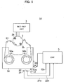
- FIG. 5 A second embodiment of a recording/reproducing apparatus of the present invention will be explained with reference to FIG. 5, FIG. 6A, FIG. 6B, FIG. 7A, FIG. 7B and FIG. 8.
- FIG. 5 is a view showing the schematic configuration of the recording/reproducing apparatus according to the second embodiment of the present invention.
- same reference numbers are used for the same components as those in the recording/reproducing apparatus 1 according to the first embodiment.
- the recording/reproducing apparatus 1A does not have the second writing prohibition detection switch 10 and the cassette type detection switch 11, but has only a writing prohibition detection switch 12 and is provided with a light emission element and light reception elements 21 and 22.
- the light emission element 20, the light reception elements 21 and 22 and the writing prohibition detection switch 12 are provided on the base 15 of the recording/reproducing apparatus 1A at positions illustrated in FIG. 6A, FIG. 6B, FIG. 7A and FIG. 7B.
- the writing prohibition detection switch 12 is a switch for detecting whether it is permitted or prohibited to write data in a current-used format on the magnetic tape 51 accommodated in the current-used tape cassette 50B in the same way as in the case of the first embodiment.
- the light reception element 21 is an element for detecting whether it is permitted or prohibited to write data in a new format on the magnetic tape 51 accommodated in the new tape cassette 50C as same as the second writing prohibition detection switch 10.
- the second light reception element 22 is an element for discriminating between the current-used tape cassette 50B and the new tape cassette 50C as same as the cassette type detection switch 11. Namely, in the recording/reproducing apparatus 1A of the second embodiment, instead of the second writing prohibition detection switch 10 and the cassette type detection switch 11, permission or prohibition of data writing in the second format and discrimination of cassettes are detected optically.
- the light emission element 20 is composed of a light emitting diode and laser, etc. Below, a case of a light emitting diode (LED) as the light emission element 20 will be explained. Of course, a laser can be also used as the light emission element 20.
- the light emission element 20 is arranged at a predetermined position on the tape cassette 50 (a current-used tape cassette 50B or a new tape cassette 50C) and emits an LED light L to the tape cassette 50.
- the light emission element 20 is driven by a control device 5.
- the light reception elements 21 and 22 are arranged at predetermined positions on the tape cassette 50.
- the tape cassette 50 has a higher format (in the case of the new tape cassette 50C)
- one of the light reception elements 21 and 22 receives an LED light L output from the light emission element 20.
- Which of the light reception elements 21 and 22 receives the LED light L is decided in accordance with a writing prohibition state of the new tape cassette 50C. Note that a configuration example of the new tape cassette 50C will be explained later on.
- the light reception elements 21 and 22 When the light reception elements 21 and 22 receive the LED light L, it is converted to an electric signal, and detection signals 21s and 22s are respectively output to the control circuit 5.
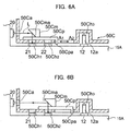
- FIG. 6A and FIG. 6B are sectional views showing an example of an arrangement relationship of a partial section of the new tape cassette 50C, a writing prohibition detection switch 12, a light emission element 20 and light reception elements 21 and 22, wherein FIG. 6A is a view showing a state of permitting data writing to the new tape cassette 50A, and FIG. 6B is a view showing a state of prohibiting data writing to the new tape cassette 50A.
- the new tape cassette 50C is provided with an discrimination hole 50Ch3 on a side surface contacting the first writing prohibition detection switch 12. Also, a light incident hole 50Ca formed on a side surface facing to the light emission element 20, a first emission hole 50Ch1 formed on a side surface facing to the light reception element 21, a second emission hole 50Ch2 formed on a side surface facing to the light reception element 22, and a slide member 50Cp for sliding a reflection member 50Cm are provided.
- the new tape cassette 50C other than the light incident hole 50Ca, the first emission hole 50Ch1 and the second emission hole 50Ch2 provided on the new tape cassette 50C is formed, for example, by a plastic resin which is opaque.
- the discrimination hole 50Ch3 is formed at the same position as the writing prohibition discrimination hole 50Bh formed on the current-used tape cassette 50B illustrated in FIG. 7A and FIG. 7B and has approximately the same shape with that of the writing prohibition discrimination hole 50Bh.
- the light incident hole 50Ca introduces the LED light L output from the light emission element 20 into the new tape cassette 50C, so that it irradiates a reflection surface 50Cma of the reflection member 50Cm.
- the reflection member 50Cm is fixed to the slide member 50Cp.
- the reflection member 50Cm deflects the direction of the incident LED light L to the substantially vertical direction by the reflection surface 50Cma.
- the slide member 50Cp is provided being able to move in the directions of arrows A1 and A2 and has an operation portion 50Cpa projecting outside of the new tape cassette 50C.
- the slide member 50Cp sets to permit data writing to the new tape cassette 50C when moved in the arrow A1 direction, while sets to prohibit data writing to the new tape cassette 50C when moved in the arrow A2 direction.
- the emission hole 50Ch1 is arranged above the light reception element 21 and guides the LED light L reflected on the reflection surface 50Cma of the reflection member 50Cm to the light reception element 21.
- the emission hole 50Ch2 is arranged above the light receiving element 21 and guides the LED light L reflected on the reflection surface 50Cma of the reflection member 50Cm to the light reception element 22.
- the operation portion 50Cpa of the slide member 50Cp is moved in the arrow A1 direction.
- This position is a position of setting to permit writing to the new tape cassette 50C.
- the reflection surface 50Cma of the reflection member 50Cm positions above the emission hole 50Ch1.
- the LED light L irradiates the light reception element 21.
- the operation portion 50Cpa of the slide member 50Cp is moved in the arrow A2 direction.
- This position is a position of setting to prohibit writing to the new tape cassette 50C.
- the reflection surface 50Cma of the reflection member 50Cm positions above the emission hole 50Cha.
- the LED light L irradiates the light reception element 22.
- FIG. 7A and FIG. 7B are sectional views showing an example of an arrangement relationship of the first writing prohibition detection switch 12 and the light reception elements 21 and 22 of the current-used tape cassette 50B, wherein FIG. 7A is a view showing a state of permitting data writing to the current-used tape cassette 50B, and FIG. 7B is a view showing a state of prohibiting data writing to the current-used tape cassette 50B.
- the outer appearance configuration of the current-used tape cassette 50B is the same as the configuration of the current-used tape cassette 50B in the first embodiment.
- the LED light L from the light emission element 20 is blocked by a side surface of the current-used tape cassette 50B facing to the light emission element 20, so that neither of the light receiving elements 21 nor 22 is irradiated.
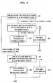
- FIG. 8 is a flowchart of operations of the second embodiment.
- Step 11 The control circuit 5 of the recording/reproducing apparatus 1A identifies as a new tape cassette 50C when either one of the light reception elements 21 and 22 receives the LED L.
- Step 12 to 13 The control circuit 5 judges that the new tape cassette 50C is in a state of permitting data writing when the light receiving element 21 receives the LED light L and controls the magnetic recording/reproducing circuit 3 so that data is recorded in the new (second) format on the magnetic tape 51 accommodated in the new tape cassette 50C.
- Step 14 to 15 The control circuit 5 judges that the new tape cassette 50C is in a state of prohibiting data writing when the light receiving element 22 receives the LED light L and does not perform recording of data on the magnetic tape 51 accommodated in the new tape cassette 50C.
- Step 16 to 18 The control circuit 5 identifies that a current-used tape cassette 50B is set in the recording/reproducing apparatus when neither of the light reception elements 21 nor 22 receives the LED light L, and when detected that the first writing prohibition detection switch 12 is in the state of permitting writing, the control circuit 5 controls the magnetic recording/reproducing circuit 3 to perform writing of data in the current-used format on the magnetic tape 51 accommodated in the current-used tape cassette 50B. When detected that the first writing prohibition detection switch 12 is in the state of prohibiting writing, the control circuit 5 does not perform data writing.
- the discrimination hole 50Ch3 as same as the writing prohibition discrimination hole 50Bh formed on the current-used tape cassette 50B, recorded contents on the magnetic tape 51 accommodated in the new tape cassette 50C is not erroneously erased by the current-used format.
- the new tape cassette 50C is identified by whether or not the light receiving elements 21 and 22 receives a light, and a hole formed on the tape cassette side, the second writing prohibition detection switch 10, the cassette detection switch 11, and other mechanisms and movable portions for identifying the new tape cassette 50C in the writing prohibition state become unnecessary, so that a mechanism for discriminating tape cassettes and detecting of writing prohibition can be simplified.
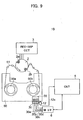
- a recording/reproducing apparatus as a third embodiment of the present invention will be explained with reference to FIG. 9 to FIG. 12.
- FIG. 9 is a view showing the schematic configuration of the recording/reproducing apparatus according to the third embodiment of the present invention.
- the recording/reproducing apparatus 1B is not provided with the second writing prohibition detection switch 10 and the cassette detection switch 11 but provided with a first writing prohibition detection switch 12.
- the recording/reproducing apparatus 1B comprises a connection terminal 30 connected to an IC memory 55 incorporated in a tape cassette 50 and a memory interface 6 connected to the connection terminal 30.
- MIC memory incorporated cassette
- an IC memory made by a non-volatile semiconductor memory such as an EEPROM
- the IC memory in the MIC stores a recorded content, title, date, time, message, recording format, and index information of timer programming, etc.
- a maker option region is secured in the IC memory, on which a user can freely record various data.
- connection terminal 30 is connected to a power source line 30a, a serial data input line 30b, a serial data output line 30c and a ground line 30d and connected to a memory interface 6.
- the memory interface 6 for connecting the IC memory 55 to the ground and supplying power to the IC memory 55 reads data recorded in the IC memory 55 as serial data to the control circuit 5 and transmits data to be recorded in the IC memory 55 as serial data from the control circuit 5 to the IC memory 55.
- the control device 5 transmits data to be written in the IC memory 55 to the memory interface 6 and receives data read from the IC memory 55 by the memory interface 6.
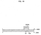
- FIG. 10 is a sectional view showing an example of a partial outer appearance of the new tape cassette 50D accommodating the magnetic tape 51, wherein data is recorded in the new format (first format) and an arrangement of the first writing prohibition detection switch 12.
- the new tape cassette 50D is formed on a side surface facing to (contacting) the first writing prohibition detection switch 12 an discrimination hole 50Dh in the same way as the writing prohibition discrimination hole 50Bh formed on the current-used tape cassette 50B shown as an example in FIG. 2A and FIG. 2B.
- the new tape cassette 50D has entirely the same configuration as that of the current-used tape cassette 50B except that there is not a cap for opening or closing the discrimination hole 50Dh.
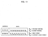
- FIG. 11 is a view showing data in a specific address in the maker option region of the IC memory 55.
- FIG. 12 is a flowchart showing operations of a recording apparatus of the third embodiment.
- Step S21 When a new tape cassette 50D having the above configuration is set in the recording/reproducing apparatus 1B, information in the lowermost bits a 0 and b 0 of the addresses "AAAA" and "BBBB" of the IC memory 55 is transmitted to the control circuit 5 via the memory interface 6, so that the control circuit 5 receives the information as it is.
- Step 22 The control circuit 5 identifies if it is a new tape cassette 50D or a current-used tape cassette 50B from the information in the lowermost bit b 0 of the address "BBBB".
- Step 23 to 25 The control circuit 5 detects if it is prohibited to write to the new tape cassette 50D from the information of the lowermost bit a 0 of the address "AAAA".
- Step 22, 26 to 28 When the current-used tape cassette 50B is set in the recording/reproducing apparatus 1B, the control circuit 5 identifies that it is a current-used tape cassette 50B from the information on the lowermost bit b 0 of the address "BBBB". Then, the control circuit 5 controls the magnetic recording/reproducing circuit 3 and the rotation drum 2, so that data recording in the current-used format is performed on the magnetic tape 51 accommodated in the current-used tape cassette 50B in accordance with a state of a detection signal of the first writing prohibition detection switch 12. Namely, when the pin 12a of the first writing prohibition detection switch 12 is in the receded state, data writing processing in the current-used format is performed, while data writing is prohibited in an inverse case.
- the third embodiment by storing discrimination information of a tape cassette and writing prohibition information of a new tape cassette 50D in advance in the IC memory 55 incorporated in the tape cassette 50 (a current-used tape cassette 50B or a new tape cassette 50D) and detecting the information by the control circuit 5 of the recording/reproducing apparatus 1B, data recording on the magnetic tape 51 accommodated in the new tape cassette 50D or data writing on the magnetic tape 51 accommodated in the current-used tape cassette 50B can be performed.
- the new tape cassette 50D is provided with a writing prohibition discrimination hole 50Dh, there is no erroneous erasing of rewriting information recorded on the magnetic tape 51 accommodated in the new tape cassette 50D by a current-used format.
- the recording/reproducing apparatuses explained in the above embodiments are configured to be able to record to both of a tape cassette wherein data is recorded in the new (second) format and a tape cassette wherein data is recorded in the current-used (first) format, but it can be also applied to a recording/reproducing apparatus capable of recording only to a tape cassette wherein data is recorded in the new format.
- a current-used tape cassette 50B is detected in the recording/reproducing apparatus (control circuit 5)
- a tape cassette ejection mechanism (not shown) is driven by the control circuit 5 and the current-used tape cassette 50B is automatically ejected from the recording/reproducing apparatus.
- a cassette having the same shape and same dimensions as those of the current-used cassette can be used, and data can be recorded in a recording medium accommodated in either of the cassettes for recording data in the new format and in the current-used format.
- the mechanism for discriminating a cassette and the configuration are minimized.
- data recorded in the new format on a recording medium is not erroneously erased by the current-used format by a current-used recording apparatus.
Landscapes
- Engineering & Computer Science (AREA)
- Computer Security & Cryptography (AREA)
- Management Or Editing Of Information On Record Carriers (AREA)
Applications Claiming Priority (3)
| Application Number | Priority Date | Filing Date | Title |
|---|---|---|---|
| JP2002166055A JP2004014009A (ja) | 2002-06-06 | 2002-06-06 | 記録装置 |
| JP2002166055 | 2002-06-06 | ||
| PCT/JP2003/007206 WO2003105147A1 (fr) | 2002-06-06 | 2003-06-06 | Dispositif d'enregistrement et cassette contenant un support d'enregistrement |
Publications (2)
| Publication Number | Publication Date |
|---|---|
| EP1511029A1 true EP1511029A1 (fr) | 2005-03-02 |
| EP1511029A4 EP1511029A4 (fr) | 2007-04-04 |
Family
ID=29727618
Family Applications (1)
| Application Number | Title | Priority Date | Filing Date |
|---|---|---|---|
| EP03757198A Withdrawn EP1511029A4 (fr) | 2002-06-06 | 2003-06-06 | Dispositif d'enregistrement et cassette contenant un support d'enregistrement |
Country Status (6)
| Country | Link |
|---|---|
| US (1) | US7515370B2 (fr) |
| EP (1) | EP1511029A4 (fr) |
| JP (1) | JP2004014009A (fr) |
| KR (1) | KR20050002797A (fr) |
| CN (1) | CN1543646A (fr) |
| WO (1) | WO2003105147A1 (fr) |
Families Citing this family (9)
| Publication number | Priority date | Publication date | Assignee | Title |
|---|---|---|---|---|
| JP2003317346A (ja) * | 2002-04-19 | 2003-11-07 | Sony Corp | 記録再生装置及び記録媒体カセット |
| US7359153B2 (en) * | 2004-07-28 | 2008-04-15 | Fujifilm Corporation | Recording medium cartridge |
| WO2010073601A1 (fr) * | 2008-12-25 | 2010-07-01 | Brother Kogyo Kabushiki Kaisha | Cassette et imprimante sur bande |
| EP2965916B1 (fr) * | 2008-12-25 | 2021-03-03 | Brother Kogyo Kabushiki Kaisha | Cassette de bande et imprimante de bande |
| CN101850665B (zh) | 2009-03-31 | 2015-01-14 | 兄弟工业株式会社 | 带盒 |
| US12296580B2 (en) | 2009-03-31 | 2025-05-13 | Brother Kogyo Kabushiki Kaisha | Tape cassette |
| EP2415610B1 (fr) | 2009-03-31 | 2019-07-03 | Brother Kogyo Kabushiki Kaisha | Cassette |
| WO2011001487A1 (fr) | 2009-06-30 | 2011-01-06 | Brother Kogyo Kabushiki Kaisha | Cassette a bande et imprimante sur bande |
| EP2520437B1 (fr) | 2009-12-28 | 2015-05-20 | Brother Kogyo Kabushiki Kaisha | Cassette à bande |
Family Cites Families (14)
| Publication number | Priority date | Publication date | Assignee | Title |
|---|---|---|---|---|
| JP2545885B2 (ja) * | 1987-10-16 | 1996-10-23 | ソニー株式会社 | テープカセット |
| JP2983998B2 (ja) * | 1989-02-07 | 1999-11-29 | ソニー株式会社 | 記録装置 |
| US5239437A (en) * | 1991-08-12 | 1993-08-24 | Minnesota Mining And Manufacturing Company | Self identifying universal data storage element |
| JP2807119B2 (ja) * | 1992-03-18 | 1998-10-08 | シャープ株式会社 | 磁気テープ装置のカセット検出装置 |
| JPH05325488A (ja) | 1992-05-27 | 1993-12-10 | Sony Corp | ディジタルテープカセット及びディジタルデータ記録装置 |
| JPH07240082A (ja) * | 1994-02-25 | 1995-09-12 | Sony Corp | テープカセット |
| JPH08124350A (ja) | 1994-10-21 | 1996-05-17 | Canon Inc | 記録媒体カセット |
| JPH11185441A (ja) | 1997-12-24 | 1999-07-09 | Aiwa Co Ltd | データストレージ用カセットおよびデータ用記録再生装置 |
| JP2000076824A (ja) | 1998-08-26 | 2000-03-14 | Sony Corp | 記録媒体収納カートリッジ、検出装置および検出方法、ならびに、記録または再生装置 |
| EP1052642B1 (fr) * | 1998-09-25 | 2006-12-20 | Sony Corporation | Cassette a bande |
| JP2000100120A (ja) | 1998-09-25 | 2000-04-07 | Sony Corp | テープカセットにおけるテープ種別識別方法 |
| JP2000100121A (ja) | 1998-09-25 | 2000-04-07 | Sony Corp | テープカセットの書き込み禁止構造 |
| JP2000348463A (ja) * | 1999-06-07 | 2000-12-15 | Tdk Corp | テープカートリッジ |
| JP2003051174A (ja) * | 2001-05-15 | 2003-02-21 | Fuji Photo Film Co Ltd | カートリッジ、及び、ドライブ装置 |
-
2002
- 2002-06-06 JP JP2002166055A patent/JP2004014009A/ja active Pending
-
2003
- 2003-06-06 CN CNA038007843A patent/CN1543646A/zh active Pending
- 2003-06-06 KR KR10-2004-7001767A patent/KR20050002797A/ko not_active Withdrawn
- 2003-06-06 EP EP03757198A patent/EP1511029A4/fr not_active Withdrawn
- 2003-06-06 US US10/485,810 patent/US7515370B2/en not_active Expired - Fee Related
- 2003-06-06 WO PCT/JP2003/007206 patent/WO2003105147A1/fr not_active Ceased
Also Published As
| Publication number | Publication date |
|---|---|
| KR20050002797A (ko) | 2005-01-10 |
| EP1511029A4 (fr) | 2007-04-04 |
| US7515370B2 (en) | 2009-04-07 |
| JP2004014009A (ja) | 2004-01-15 |
| US20050117881A1 (en) | 2005-06-02 |
| WO2003105147A1 (fr) | 2003-12-18 |
| CN1543646A (zh) | 2004-11-03 |
Similar Documents
| Publication | Publication Date | Title |
|---|---|---|
| US20080170330A1 (en) | Recording medium cartridge | |
| US7515370B2 (en) | Recorder and cassette containing recording medium | |
| US6603725B2 (en) | Disk cartridge apparatus | |
| KR100338448B1 (ko) | 내부에기록매체를유지하는다양한치수의카세트및신호기록재생시스템 | |
| EP1052642B1 (fr) | Cassette a bande | |
| WO1997022970A1 (fr) | Cartouche et lecteur pour disques magnetiques | |
| EP0637026B1 (fr) | Appareil à cassette | |
| US6452746B1 (en) | Tape cassette | |
| CN1323403C (zh) | 记录介质盒 | |
| US7113368B2 (en) | Recording and reproducing apparatus for preventing erroneous erasure | |
| JP3093808B2 (ja) | 情報記録再生装置 | |
| JPH02172083A (ja) | 記録媒体及び記録媒体用ドライブ装置及び記録再生システム | |
| JP2006040435A (ja) | 記録メディアカートリッジ | |
| JPH05334786A (ja) | 円盤状記録媒体用の記録及び/又は再生装置及び円盤状記録媒体用の記録及び/又は再生装置に用いられるカートリッジ | |
| JPH0963241A (ja) | 磁気ディスクカートリッジ | |
| JP2000076824A (ja) | 記録媒体収納カートリッジ、検出装置および検出方法、ならびに、記録または再生装置 | |
| JPH0442485A (ja) | ハードケース収納形磁気記憶媒体 | |
| JPS6371962A (ja) | 光磁気記録媒体情報消去装置 | |
| WO2005038798A1 (fr) | Dispositif d'enregistrement/reproduction d'information | |
| JPH09237483A (ja) | ディスクカートリッジ | |
| CN101971261A (zh) | 记录介质盒 | |
| JPH08235808A (ja) | ディスクジャケット | |
| KR19980032076U (ko) | 컴퓨터기기의 드라이브장치 | |
| JPH03238664A (ja) | フロッピーディスクの媒体属性の識別方法 | |
| JPH1186506A (ja) | 情報記録媒体用カートリッジ及び情報記録再生装置 |
Legal Events
| Date | Code | Title | Description |
|---|---|---|---|
| PUAI | Public reference made under article 153(3) epc to a published international application that has entered the european phase |
Free format text: ORIGINAL CODE: 0009012 |
|
| 17P | Request for examination filed |
Effective date: 20040206 |
|
| AK | Designated contracting states |
Kind code of ref document: A1 Designated state(s): AT BE BG CH CY CZ DE DK EE ES FI FR GB GR HU IE IT LI LU MC NL PT RO SE SI SK TR |
|
| AX | Request for extension of the european patent |
Extension state: AL LT LV MK |
|
| DAX | Request for extension of the european patent (deleted) | ||
| RBV | Designated contracting states (corrected) |
Designated state(s): DE GB |
|
| A4 | Supplementary search report drawn up and despatched |
Effective date: 20070305 |
|
| 17Q | First examination report despatched |
Effective date: 20070820 |
|
| STAA | Information on the status of an ep patent application or granted ep patent |
Free format text: STATUS: THE APPLICATION IS DEEMED TO BE WITHDRAWN |
|
| 18D | Application deemed to be withdrawn |
Effective date: 20080103 |