EP1510725B1 - Viscous damper - Google Patents
Viscous damper Download PDFInfo
- Publication number
- EP1510725B1 EP1510725B1 EP03733221A EP03733221A EP1510725B1 EP 1510725 B1 EP1510725 B1 EP 1510725B1 EP 03733221 A EP03733221 A EP 03733221A EP 03733221 A EP03733221 A EP 03733221A EP 1510725 B1 EP1510725 B1 EP 1510725B1
- Authority
- EP
- European Patent Office
- Prior art keywords
- annular
- inertia mass
- mass element
- concave
- convex portion
- Prior art date
- Legal status (The legal status is an assumption and is not a legal conclusion. Google has not performed a legal analysis and makes no representation as to the accuracy of the status listed.)
- Expired - Fee Related
Links
Images


Classifications
-
- F—MECHANICAL ENGINEERING; LIGHTING; HEATING; WEAPONS; BLASTING
- F16—ENGINEERING ELEMENTS AND UNITS; GENERAL MEASURES FOR PRODUCING AND MAINTAINING EFFECTIVE FUNCTIONING OF MACHINES OR INSTALLATIONS; THERMAL INSULATION IN GENERAL
- F16F—SPRINGS; SHOCK-ABSORBERS; MEANS FOR DAMPING VIBRATION
- F16F15/00—Suppression of vibrations in systems; Means or arrangements for avoiding or reducing out-of-balance forces, e.g. due to motion
- F16F15/10—Suppression of vibrations in rotating systems by making use of members moving with the system
- F16F15/16—Suppression of vibrations in rotating systems by making use of members moving with the system using a fluid or pasty material
- F16F15/167—Suppression of vibrations in rotating systems by making use of members moving with the system using a fluid or pasty material having an inertia member, e.g. ring
- F16F15/173—Suppression of vibrations in rotating systems by making use of members moving with the system using a fluid or pasty material having an inertia member, e.g. ring provided within a closed housing
-
- Y—GENERAL TAGGING OF NEW TECHNOLOGICAL DEVELOPMENTS; GENERAL TAGGING OF CROSS-SECTIONAL TECHNOLOGIES SPANNING OVER SEVERAL SECTIONS OF THE IPC; TECHNICAL SUBJECTS COVERED BY FORMER USPC CROSS-REFERENCE ART COLLECTIONS [XRACs] AND DIGESTS
- Y10—TECHNICAL SUBJECTS COVERED BY FORMER USPC
- Y10T—TECHNICAL SUBJECTS COVERED BY FORMER US CLASSIFICATION
- Y10T74/00—Machine element or mechanism
- Y10T74/21—Elements
- Y10T74/2121—Flywheel, motion smoothing-type
- Y10T74/2122—Flywheel, motion smoothing-type with fluid balancing means
-
- Y—GENERAL TAGGING OF NEW TECHNOLOGICAL DEVELOPMENTS; GENERAL TAGGING OF CROSS-SECTIONAL TECHNOLOGIES SPANNING OVER SEVERAL SECTIONS OF THE IPC; TECHNICAL SUBJECTS COVERED BY FORMER USPC CROSS-REFERENCE ART COLLECTIONS [XRACs] AND DIGESTS
- Y10—TECHNICAL SUBJECTS COVERED BY FORMER USPC
- Y10T—TECHNICAL SUBJECTS COVERED BY FORMER US CLASSIFICATION
- Y10T74/00—Machine element or mechanism
- Y10T74/21—Elements
- Y10T74/2173—Cranks and wrist pins
- Y10T74/2183—Counterbalanced
- Y10T74/2184—Vibration dampers
Definitions
- the present invention relates to a viscous damper mounted on a shaft of an internal combustion engine such as an engine of an automobile.
- a viscous damper for absorbing a torsional vibration of a crankshaft of an internal combustion engine includes a case 3 with an opening 2a provided at one side in an axial direction of an annular case body 2 substantially U-shaped in section being closed with a cover 7 to be liquid-sealed, and an annular inertia mass element 4 housed with a damping liquid (not shown) inside the case 3, and the viscous damper is fixed with a bolt to a revolving shaft 1 of the internal combustion engine via a mounting portion 2c integrally formed at the case body 2.
- a closed chamber 2b is defined by the case body 2 and the cover 7, the inertia mass element 4 is placed rotatably in a circumferential direction in the closed chamber 2b with its both sides in an axial direction being supported by thrust bearings 5, and with an inner circumferential surface of the inertia mass element 4 being supported by a journal bearing 6.
- the thrust bearing 5 is constituted of a disc of a material with lubricity such as a nylon resin, and is mounted by being fitted in a shallow mounting hole 8 formed on both side surfaces in a diameter direction of the inertia mass element 4.
- the thrust bearings 5 abut to an inner surface of an orthogonal wall at an opposite side from an open side of the case body 2 and an inner surface of the cover 7, and rotatably support the inertia mass body 4 in a circumferential direction with a fixed narrow clearance being kept between these inner surfaces.
- the journal bearing 6 is constituted of an annular ring of a nylon resin or the like, and formed to be an open ring cut at one spot.
- the journal bearing 6 is placed between an inner circumferential surface of the inertia mass element 4 and an inner surface of an inner circumferential wall of the case body 2, and supports the inertia mass element 4 rotatably in the circumferential direction with a fixed narrow clearance being kept from the inner surface (refer to, for example, Japanese Utility Model No. 2579119 ).
- this viscous damper needs to adjust the inertia mass element 4 correspondingly to the characteristic of the internal combustion engine to which the viscous damper is applied, and if the inertia mass element 4 is changed, the case body 2 and the cover 7 need to be changed.
- the inertia mass element 4 is generally formed by casting due to less waste of the material and its suitability for mass production, and if the inertia mass element is changed, the casting die has to be changed.
- the damping force of a viscous damper is derived from occurance of a shear resistence force to the damping liquid with high viscosity existing between the case 3 and the inertia mass element 4 when a relative speed difference between the case 3 and the inertia mass element 4 occurs, and therefore the damping force is influenced not only by the dimension of the clearance between the case 3 and the inertia mass element 4 but also by the conditions of the inner surface of the case 3 and the outer surface of the inertia mass element 4 to a large extent. Consequently, the cast inertia mass element needs finishing work on its surface by cutting or the like, and therefore the production process is complicated.
- a viscous damper is also known in which the inertia mass element is comprised of a laminate made of annular plates (see, for instance, EP-A-0 013 129 ).
- the inertia mass element is formed by bonding a plurality of annular plates by welding.
- the entrance part of claim 1 is based on the document EP-A-0 013 129 .
- the production process is again complicated.
- an object of the present invention is to provide a viscous damper improved in general versatility, easy to produce, and capable of reduction in the production cost.
- the mass of the inertia mass element can be easily adjusted by increasing and decreasing the number of annular plates to be laminated, increasing and decreasing the specific gravity of the annular plates, and the like. Accordingly, the mass adjustment of the inertia mass element corresponding to the vibration characteristic of the internal combustion engine to which the viscous damper is applied can be facilitated, and general versatility of the viscous damper can be further improved.
- the annular plate is formed by joining a plurality of arc-shaped ring pieces in an annular form.
- the annular plate may be punched out in its entirety by a press, but if a plurality of parts are assembled to form the annular plate, waste of the material can be reduced.
- a plurality of ring pieces are placed in an annular form, and by close-fitting a protruded piece formed at one end of one ring piece of the adjacent ring pieces into a hole formed at a corresponding one end of the other ring piece, a plurality of ring pieces are joined in the annular form.
- a concave portion can be formed at least at one side of a base portion of the protruded piece of the ring piece, and a protruded portion fitted in the concave portion is formed at a corresponding side of an open end of the hole.
- FIG. 1 is a sectional view showing an essential part of one embodiment of a viscous damper of the present invention
- FIG. 2 is a plan view showing a part of an annular plate used in an inertia mass element of the damper in FIG. 1 .
- the viscous damper is constituted of a case 10 in which an opening 12d toward one side, in an axial direction, of an annular case body 12 substantially U-shaped in section is closed with a cover 7 to be liquid-sealed, an annular inertia mass element 14 housed with a damping liquid inside the case 10, and a hub 11 for fixing the case 10 to a revolving shaft of an internal combustion engine, for example, a crankshaft (not shown) of an automobile engine.
- a hub 11 is made by pressing a plate material to have an annular fixing portion 11b at an outer circumference, and is attached to a revolving shaft of an internal combustion engine via a mounting hole 11a provided near a center in its diameter direction, and the case body 12 is attached to an annular fixing portion 11b at the outer circumference.
- the case body 12 is fitted to the annular fixing portion 11b at the outer circumference of the hub 11, and by welding the case body 12 and the annular fixing portion 11b in the circumferential direction at positions of both sides in the axial direction, the case body 12 is fixed to the annular fixing portion 11b.
- a closed chamber 13 substantially rectangular in section is defined inside by an inner circumferential wall 12a, an outer circumferential wall 12b, and an orthogonal wall 12c for connecting them of the case body 12 and the cover 7.
- the inertia mass element 14 is placed inside the closed chamber 13 rotatably in the circumferential direction with both sides in its axial direction being supported by thrust bearings 5 and an inner circumferential surface of the inertia mass element 14 being supported by a journal bearing 6.
- the thrust bearings 5 are each constituted of a disc of a material with lubricity such as a nylon resin, and are attached to shallow mounting holes 8 formed on surfaces of both sides in the axial direction of the inertia mass element 14.
- the thrust bearings 5 abut to an inner surface of the orthogonal wall 12c of the case 12 and an inner surface of the cover 7, and support the inertia mass element 14 rotatably in a circumferential direction with a fixed narrow clearance being kept from these inner surfaces.
- the journal bearing 6 is an annular ring made of a nylon resin or the like, and is formed to be an open ring cut at one spot in a circumferential direction.
- the journal bearing 6 is attached to a shallow annular concave groove 9 provided at an inner circumferential portion of the inertia mass element 14, and is fitted onto the inner circumferential wall 12a of the case body 12.
- the journal bearing 6 abuts to the inner surface of the inner circumferential wall 12a of the case body 12, and supports the inertia mass element 14 rotatably in the circumferential direction with a fixed narrow clearance being kept from the inner surface.
- the inertia mass element 14 is a laminate made by overlaying annular plates 14a on each other and bonding them, and thin annular plates 14a1 located at both sides in an axial direction are provided with the aforesaid mounting holes 8 by punching.
- An annular plate 14a2 located in a center part in a width direction (axial direction) of the inertia mass element 14 has an inner diameter made a little smaller than the other annular plates 14a and 14a1, whereby the aforesaid concave groove 9 is formed on an inner circumferential portion of the inertia mass element 14.
- the case body 12 can be formed by cold forging of a plate material or by pressing work of a plate material.
- a plate material a cold-rolled steel plate defined by Japanese Industrial Standard JIS G3141 or a steel strip SPCC (for general purpose), SPCD (for drawing), SPCE (for deep drawing) and the like can be used.
- SPCC for general purpose
- SPCD for drawing
- SPCE for deep drawing
- annular plates 14a including the annular plates 14a1 and 14a2
- an adhesive can be used, but as will be described later, by forming bonding pieces on the annular plates 14a and pressing the laminate of the annular plates, the annular plates can be mechanically bonded to each other with the bonding pieces.
- the annular plate 14a itself can be formed by pressing work of a plate material.
- the annular plate may be punched out in its entirety, or arc-shaped ring pieces, which are a plurality of divided parts of the annular plate in its circumferential direction, may be punched out, while at the same time, engaging pieces are formed at the ring pieces, and the ring pieces may be bonded at the engaging pieces by a press to form the annular plate.
- the plate material SPCC, SPCD, SPCE and the like can be used.
- a plurality of annular plates 14a are laminated to form the inertia mass element 14, and therefore the mass of the inertia mass element can be adjusted by increasing and decreasing the number of annular plates 14a to be laminated and by increasing and decreasing the thickness of the annular plate.
- the inertia mass element 14 having high dimensional precision can be obtained. Accordingly, the mass adjustment of the inertia mass element 14 corresponding to the vibration characteristic of the internal combustion engine to which the inertia mass element is applied can be facilitated, thus making the viscous damper high in general versatility.
- the mass adjustment of the inertia mass element 14 can be also easily realized by using the annular plates with different specific gravities.
- the mounting holes 8 of the inertia mass element 14 in which the thrust bearing 5 is fitted can be formed by a simple work of punching of the annular plates 14a1 at both sides of the inertia mass element 14.
- the concave groove 9 in which the journal bearing 6 is fitted can be easily formed by reducing the inner diameter of the annular plates 14a2 in the center part of the inertia mass element 14.
- the hub 11 for mounting is separately provided instead of integrally forming the mounting portion at the case body 12 to fix the case 10 to the revolving shaft of the internal combustion engine, and therefore the case body 12 can be easily formed.
- FIG. 3 shows another embodiment of the present invention.
- the inertia mass element 14 is formed by alternately laminating annular plates 14a3 and 14a4 with different inner diameters, and a concave and convex (difference in level) 14A in a comb-teeth shape is provided in an inner circumferential surface of the inertia mass element 14.
- a journal bearing 6A is made to be an annular element with a concave and convex 6A1 on an outer circumferential surface thereof, the concave and convex 6A1 being fitted to the concave and convex 14A with a narrow clearance existing between them, whereby the bearing 6A is given an original function of supporting the inertia mass element 14 in a diameter direction.
- the bearing 6A is also given the width to abut to inner surfaces at both sides in the axial direction of the case 10, namely, an inner surface of the orthogonal wall 12c of the case body 12 and an inner surface of the cover 7, and therefore, is given a function of the thrust bearing for supporting the inertia mass element 14 in the axial direction.
- the inertia mass element 14 can be supported rotatably in a circumferential direction by one bearing 6A, in an axial direction and a diameter direction of the inertia mass element , and the work for the thrust bearing and the mounting hole can be eliminated.
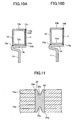
- FIG. 4 shows yet another embodiment of the present invention.
- the inertia mass element 14 is formed by alternately laminating annular plates 14a5 and 14a6 with different outer diameters, so that a concave and convex portion 14B in a comb-teeth shape is provided on an outer circumferential surface of the inertia mass element.
- a concave and convex 6Bl fitted to the aforesaid concave and convex portion 14B with a clearance existing between them is formed on an inner circumferential surface of the bearing 6B.
- the bearing 6B is given the width to abut to inner surfaces at both sides in the axial direction of the case 10, so that the bearing 6B is given the function of a thrust bearing for supporting the inertia mass element 14 in the axial direction.
- a clearance between at least one of the concave and convex 6B1 of the bearing 6B, that is, the concave and convex portion 6B1b at both sides except for a convex portion 6B1a in a center in this example, and the concave and convex portion 14B1b of the inertia mass element 14 to which the concave and convex portion 6B1b is fitted is made comparatively large, whereby the clearance between the concave and convex portions 6B1b and 14B1b becomes a clearance suitably adjusted so that a desired damping force occurs by a damping liquid existing in the clearance.
- a clearance between the convex portion 6B1a at a center of the above-described bearing 6B and the concave and convex portion 14B1a at the center of the inertia mass element 14 to which the convex portion 6B1a is fitted is made a narrow clearance to be given the supporting function in a diameter direction and an axial direction.
- convex portions 14b in a radial direction can be formed on an outer surface of the annular plates 14a located at both sides in the axial direction of the inertia mass element 14 as shown in FIG. 5 .
- a convex portion 14b By providing such a convex portion 14b, clearances from inner surfaces at both sides in the axial direction of the case 10 can be adjusted, and the degree of freedom of adjustment of the damping force is increased.
- the function of an oil reservoir can be added to the surface of the inertia mass element 14. Namely, the viscous damper is generally used with the case 10 being positioned vertically due to the placement position of the internal combustion engine, and therefore a damper liquid in the closed chamber 13 descends in a standstill state.
- the convex portions 14b are formed on the surface of both sides of the inertia mass element 14, the descending damping liquid is easily held on the surface. Consequently, it becomes possible to exhibit a damping force in a short time after the internal combustion engine is actuated.
- grooves 14c in a radial direction can be provided on their outer surface to be inclined to a tip end side in a rotational direction as shown in FIG. 6 . If such grooves 14c are provided, flow of the damping liquid can be changed, and therefore it becomes possible to adjust the damping force.
- the damping liquid leaning in the outer circumferential direction by a centrifugal force when the inertia mass element 14 is rotated can be guided in a center direction by the slantly disposed groove 14c, and therefore it is especially effective in the case in which the journal bearing is provided at a center side of the inertia mass element 14.
- the convex portions 14b and the groove 14c of the annular plates 14a can be formed at the same time when the annular plates 14 are made by a press.
- the annular plate 14a of the inertia mass element 14 may be punched out in its entirety by a press, but according to the invention a plurality of parts are assembled to form the annular plate.
- arc-shaped ring pieces 21, which are a plurality of divided parts of the annular plate in the circumferential direction, for example, four or five parts, are punched out from the long plate material 20, and at the same time, by this stamping, protruded pieces 21b are formed on the ring pieces 21 at one end, and fitting holes 21a fitted to the protruded pieces 21b are formed at the other end.
- a plurality of ring pieces 21 are arranged in the circumferential direction to be placed in an annular form, the protruded piece 21b of one of the adjacent ring pieces 21 is applied to the hole 21a of the other ring piece 21, so that the end portions of the ring pieces 21 and 21 butt against each other, and the butted end portions are pressed to close-fit the protruded piece 21b into the hole 21a, whereby a plurality of ring pieces 21 are joined and formed into the annular plate.
- the ring pieces 21 are thus punched out of the plate material 20, as many the ring pieces 21 as possible, each of which has a predetermined linear length L, are taken from the plate material 20 having the same width L or more, whereby waste of the material can be substantially eliminated.
- rectangular concave portions 21b1 are provided at both sides of a base part of the protruded piece 21b of the ring piece 21 as shown in FIG. 8(a) , and rectangular convex portions 21a1 fitted into the concave portions 21b1 are provided at both sides of an open end of the hole 21a of the ring piece 21.
- the concave portions 21b1 at a base portion of the protruded piece 21b and the convex portion 21a1 at the open end of the hole 21a may be formed only at an outer portion which easily opens. It is preferred that the concave portions 21b1 and the convex portion 21a1 are rectangular, because the rectangular shape provides a strong engaging force, but they may be formed to be circular and the like other than rectangular.
- An adhesive can be used to bond the laminated annular plates 14a, but in order to improve productivity, it is preferred to form engaging pieces at the annular plates 14a and bond them mechanically by a press.
- the engaging piece is shown in FIG. 7 , and in this example, a half blanking work is performed for a center part of the arc of the ring piece 21, and two half-blanked pieces (cut-and-bent pieces) 21c are bent and raised from the surface of the ring piece 21 to protrude.
- annular plates 14a are overlaid on each other so that the cut-and-bent pieces 21c are overlaid on each other.
- the laminate of the annular plates are pressed, and the cut-and-bent piece 21c of one of the overlaid annular plates is fitted into the hole portion of the cut-and-bent piece 21c formed at the other annular plate, whereby the annular plates are bonded to each other.
- the annular plates are bonded to each other in the close-contact state with substantially no clearance between them by deformation by a press.
- annular plate with no joint which is punched out in its entirety, may be used for the annular plate on which the cut-and-bent pieces are formed, instead of the annular plate made by joining the ring pieces, and for the annular plate with no joint, the cut-and-bent pieces are formed with spaces provided in the circumferential direction, and the laminate of the annular plates is similarly bonded by pressing.
- a dowel may be formed to perform bonding.
- a dowel 22 protruded from one surface of the ring piece 21 to the other surface is formed by a half pierce work by a press, and after the ring pieces 21 are joined to be formed into the annular plate 14a, a plurality of annular plates 14a are overlaid on each other so that the dowels 22 are displaced in the circumferential direction. It is preferred that the dowels 22 of every other annular plate 14a are overlaid on each other.
- the convex portion 22a of the dowel 22 it is preferred to form the convex portion 22a of the dowel 22 to be narrower than the concave portion 22b. If the convex portion 22a is made narrower than the concave portion 22b, the convex portion 22a can be formed to be high by ejection by half-piercing work which obtains the convex portion 22a and the concave portion 22b at the same time. Accordingly, bite of the convex portion 22a into the surface of the annular plate 14 is sharpened, which increases the engaging force, and bonding strength of the annular plates to each other becomes high. The shape stability of the obtained inertia mass element 14 is improved.
- the annular plate with the dowels being formed may be an annular plate with no joint, which is punched out in its entirety, instead of the annular plate made by joining the ring pieces.
- the dowels are formed with spaces provided in the circumferential direction, and the laminate of the annular plates is similarly bonded by pressing.
- bonding by means of pins, screws and the like may be performed in addition to or instead of the bonding by means of the dowels and the like of the annular plates 14a.
- a bonding method by means of the pins is shown in FIG. 11 .
- Pin holes 24a are formed at a plurality of spots in the circumferential direction of the annular plate 14a.
- the annular plate 14a may be the one which is punched out in its entirety by a press as the conventional ones, or may be the one which is made by punching out the arc-shaped ring pieces and bonding them, and on the punching of them, or after the punching, a hole 24 is formed by pressing.
- a plurality of annular plates 14a are overlaid on each other so that the pin holes 24 are overlaid on each other, a pin 25 having conical concave portions 25a at its both ends is inserted into the pin hole 24 of the laminate of the annular plates 14a, choking jigs (not shown) of substantially the same shape are applied to the concave portion 25a at the both ends and pressed, and the pin 25 is choked by pressing the concave portions 25a to expand from the state shown by the chain double-dashed line to the state shown by the solid line, whereby the laminated annular plates 14a are bonded.
- the viscous damper may be directly mounted on the revolving shaft of the internal combustion engine by integrally providing the mounting portion at the case body 12, but as described above, it is mounted on the revolving shaft via the hub 11 by fixing the case body 12 at the hub 11 having the annular fixing portion 11b at the outer circumference.
- the case body 12 is joined to the annular fixing portion 11b of the hub 11 by applying welding 15a, 15b in the circumferential direction to the inner circumferential wall 12a of the case body 12 and the annular fixing portion 11b at the positions of both sides in the axial direction, after it is fitted to the outer circumferential portion of the annular fixing portion 11b of the hub 11. If the strength allows, spot welding can be performed.
- FIG. 10(a) is the similar mounting method as in the prior art. Joggling work is applied to the open end portions of the inner circumferential wall 12a and the outer circumferential wall 12b of the case body 12 to provide inner and outer step portions 12e made by cutting the inner surfaces of the open end portions, and upper and lower ends of the cover 7 are fitted in the inner and outer step portions 12e, welding 15c ( FIG.
- FIG. 10 (b) shows an improved mounting method.
- a tip end of the annular fixing portion 11b of the hub 11 is protruded from the open end of the case body 12, the cover 7 is placed on the protruded tip end of the annular fixing portion 11b, so that the cover 7 is applied to the open end of the case body 12, welding 15d and welding 15e are applied in the circumferential direction to the entire circumference of the abutting portions of the upper and lower ends of the cover 7 and the outer circumferential wall 12b and the inner circumferential wall 12a of the case body 12 to join the cover 7 to the open end of the case body 12 to be liquid sealed, and by welding 15e of the lower end of the cover 7 and the inner circumferential wall 12a of the case body 12, the open end of the case body 12 and the annular fixing portion 11b of the hub 11 are joined to each other at the same time.
- welding it is preferable to use beam welding, laser welding and the like.
- the annular inertia mass element housed inside the case with the damper liquid is constructed by overlaying a plurality of annular plates comprised of ring pieces close fitted together and bonding them, and therefore the mass adjustment of the inertia mass element can be facilitated by increasing and decreasing and the like of the number of laminated annular plates, and general versatility of the viscous damper can be further improved.
Applications Claiming Priority (5)
| Application Number | Priority Date | Filing Date | Title |
|---|---|---|---|
| JP2002159193 | 2002-05-31 | ||
| JP2002159193 | 2002-05-31 | ||
| JP2003108368A JP2004053008A (ja) | 2002-05-31 | 2003-04-11 | ビスカスダンパ |
| JP2003108368 | 2003-04-11 | ||
| PCT/JP2003/006890 WO2003102442A1 (fr) | 2002-05-31 | 2003-05-30 | Amortisseur hydraulique |
Publications (3)
| Publication Number | Publication Date |
|---|---|
| EP1510725A1 EP1510725A1 (en) | 2005-03-02 |
| EP1510725A4 EP1510725A4 (en) | 2005-09-07 |
| EP1510725B1 true EP1510725B1 (en) | 2008-11-26 |
Family
ID=29714303
Family Applications (1)
| Application Number | Title | Priority Date | Filing Date |
|---|---|---|---|
| EP03733221A Expired - Fee Related EP1510725B1 (en) | 2002-05-31 | 2003-05-30 | Viscous damper |
Country Status (7)
| Country | Link |
|---|---|
| US (1) | US7448298B2 (ja) |
| EP (1) | EP1510725B1 (ja) |
| JP (1) | JP2004053008A (ja) |
| CN (1) | CN100425866C (ja) |
| AU (1) | AU2003241703A1 (ja) |
| DE (1) | DE60324919D1 (ja) |
| WO (1) | WO2003102442A1 (ja) |
Families Citing this family (14)
| Publication number | Priority date | Publication date | Assignee | Title |
|---|---|---|---|---|
| JP2007177851A (ja) * | 2005-12-27 | 2007-07-12 | Fukoku Co Ltd | ビスカスダンパー |
| JP2008057582A (ja) * | 2006-08-29 | 2008-03-13 | Bridgestone Corp | トーショナルダンパ |
| US20100175956A1 (en) * | 2009-01-13 | 2010-07-15 | Caterpillar Inc. | Viscous pendulum damper |
| EP2218939A1 (en) * | 2009-02-11 | 2010-08-18 | Converteam Technology Ltd | Rotating electrical machines |
| JP2011075514A (ja) * | 2009-10-01 | 2011-04-14 | A & D Co Ltd | エンジンベンチ |
| US20120227536A1 (en) * | 2011-03-10 | 2012-09-13 | General Electric Company | Sectioned tuning ring for rotating body |
| CN103267085B (zh) * | 2013-05-07 | 2015-12-23 | 北京化工大学 | 旋转机械转子液力多频动力吸振器 |
| JP5931945B2 (ja) * | 2014-03-18 | 2016-06-08 | 三菱重工業株式会社 | はずみ車および舶用ディーゼル機関 |
| CN105387114A (zh) * | 2015-12-08 | 2016-03-09 | 无锡亨宇减震器科技有限公司 | 防滑式橡胶隔振装置 |
| CN108035595B (zh) * | 2017-07-04 | 2019-09-27 | 同济大学 | 带独立调节刚度与承载力阻尼器的支撑结构及其设计方法 |
| US10899217B2 (en) * | 2018-07-04 | 2021-01-26 | Patrick J. Dugas | Supplemental regenerative braking system |
| GB2603674B (en) * | 2019-09-12 | 2023-06-28 | Baker Hughes Oilfield Operations Llc | Vibration isolating coupler for reducing vibrations in a drill string |
| CN110748603B (zh) * | 2019-12-26 | 2020-04-10 | 沈阳微控新能源技术有限公司 | 一种高疲劳寿命飞轮和飞轮储能系统 |
| CN115182965B (zh) * | 2022-06-24 | 2023-07-14 | 山东交通学院 | 一种阻尼扭转减振器 |
Family Cites Families (28)
| Publication number | Priority date | Publication date | Assignee | Title |
|---|---|---|---|---|
| US2198135A (en) * | 1938-11-15 | 1940-04-23 | Jesse L Strasburg | Engine vibration eliminator |
| US3285096A (en) * | 1964-07-29 | 1966-11-15 | Bernard E O'connor | Torsional vibration damper |
| US3823619A (en) * | 1972-10-27 | 1974-07-16 | Caterpillar Tractor Co | Multi-plate vibration damper |
| DE2640752C2 (de) * | 1976-09-10 | 1984-11-08 | Dirk Dr.-Ing. 8520 Erlangen Forkel | Drehschwingungsdämpfer |
| DE2640751C2 (de) * | 1976-09-10 | 1984-11-08 | Dirk Dr.-Ing. 8520 Erlangen Forkel | Drehschwingungsdämpfer |
| EP0013129A1 (en) * | 1978-12-26 | 1980-07-09 | Cummins Engine Company, Inc. | Viscous vibration damper |
| US4481840A (en) * | 1981-12-02 | 1984-11-13 | The United States Of America As Represented By The United States Department Of Energy | Layered flywheel with stress reducing construction |
| US4627635A (en) * | 1983-09-20 | 1986-12-09 | Koleda Michael T | Vibration damping units and vibration damped products |
| JPS62270845A (ja) * | 1986-05-15 | 1987-11-25 | Mitsubishi Electric Corp | 粘性ダンパ |
| JPS63293344A (ja) * | 1987-05-26 | 1988-11-30 | Mitsubishi Electric Corp | 粘性ダンパ− |
| JPH0538262Y2 (ja) * | 1987-11-06 | 1993-09-28 | ||
| JPH0260706U (ja) * | 1988-10-28 | 1990-05-07 | ||
| US5058453A (en) * | 1989-05-05 | 1991-10-22 | Caterpillar Inc. | Torsional vibration damper |
| JP2632230B2 (ja) * | 1990-04-20 | 1997-07-23 | 株式会社 シーゲル | 慣性ダンパ |
| JPH0564554U (ja) * | 1992-02-07 | 1993-08-27 | エヌ・オー・ケー・メグラスティック株式会社 | 回転変動吸収プーリ |
| JP2579119B2 (ja) | 1993-03-15 | 1997-02-05 | 方正 彭 | 誘導電動機のベクトル制御装置 |
| JP3672330B2 (ja) * | 1993-04-05 | 2005-07-20 | トヨタ自動車株式会社 | 制振構造体 |
| JPH08200449A (ja) * | 1995-01-30 | 1996-08-06 | Toyota Central Res & Dev Lab Inc | ねじり振動減衰粘性ダンパ |
| US5749269A (en) * | 1996-04-26 | 1998-05-12 | Vibratech, Inc. | Dual-mode, viscous crankshaft vibration damper |
| DE19621460C1 (de) * | 1996-05-29 | 1997-07-31 | Palsis Schwingungstechnik Gmbh | Bauteil zur Übertragung von Drehbewegungen und zur Drehschwingungsdämpfung |
| JPH10202332A (ja) * | 1997-01-21 | 1998-08-04 | Matsushita Electric Ind Co Ltd | 積層プレス品およびその製造装置 |
| US6223574B1 (en) * | 1997-05-14 | 2001-05-01 | Suncall Corporation | Thin-walled ring-shaped member and method of manufacturing same |
| JP3570204B2 (ja) * | 1998-02-12 | 2004-09-29 | Nok株式会社 | イナーシャダンパ |
| JP3686764B2 (ja) * | 1998-11-30 | 2005-08-24 | Tdk株式会社 | マグネットダンパ |
| AU2001296595A1 (en) * | 2000-10-02 | 2002-04-15 | Indigo Energy, Inc. | Stacked disc flywheel |
| EP1233206B1 (en) * | 2001-02-14 | 2008-07-30 | Oiles Corporation | Damper and automobile seat having the damper |
| JP2003028243A (ja) * | 2001-07-18 | 2003-01-29 | Walbro Japan Inc | フライホイールの平衡錘 |
| JP2003322184A (ja) * | 2002-05-09 | 2003-11-14 | Nsk Warner Kk | 摩擦板の製造方法及び装置 |
-
2003
- 2003-04-11 JP JP2003108368A patent/JP2004053008A/ja active Pending
- 2003-05-30 DE DE60324919T patent/DE60324919D1/de not_active Expired - Fee Related
- 2003-05-30 EP EP03733221A patent/EP1510725B1/en not_active Expired - Fee Related
- 2003-05-30 CN CNB038154218A patent/CN100425866C/zh not_active Expired - Fee Related
- 2003-05-30 US US10/514,551 patent/US7448298B2/en not_active Expired - Fee Related
- 2003-05-30 WO PCT/JP2003/006890 patent/WO2003102442A1/ja active Application Filing
- 2003-05-30 AU AU2003241703A patent/AU2003241703A1/en not_active Abandoned
Also Published As
| Publication number | Publication date |
|---|---|
| DE60324919D1 (de) | 2009-01-08 |
| CN1666035A (zh) | 2005-09-07 |
| US20050235943A1 (en) | 2005-10-27 |
| US7448298B2 (en) | 2008-11-11 |
| EP1510725A1 (en) | 2005-03-02 |
| WO2003102442A1 (fr) | 2003-12-11 |
| EP1510725A4 (en) | 2005-09-07 |
| CN100425866C (zh) | 2008-10-15 |
| JP2004053008A (ja) | 2004-02-19 |
| AU2003241703A1 (en) | 2003-12-19 |
Similar Documents
| Publication | Publication Date | Title |
|---|---|---|
| EP1510725B1 (en) | Viscous damper | |
| CN100595452C (zh) | 变矩器 | |
| KR100951630B1 (ko) | 동압 베어링 장치 | |
| US5778738A (en) | Two-mass type of flywheel device | |
| EP0423243B1 (en) | Torsional vibration damper | |
| US8038554B2 (en) | Isolation damper pulley and method of producing the same | |
| US8939123B2 (en) | Countershaft | |
| US5480362A (en) | Double planetary carrier | |
| EP1146254B1 (en) | Carrier and method of manufacturing carrier | |
| US6793394B2 (en) | Hydrodynamic bearing device | |
| EP1510724B1 (en) | Tortional damper pulley | |
| JP2009500581A (ja) | 振動減衰装置、特にデュアルマスフライホイール | |
| JP3520502B2 (ja) | 同軸のカバーと、基板と、リング体を組立る方法 | |
| JPS58156773A (ja) | 遊星歯車キヤリア組立体 | |
| JP2003505249A (ja) | 摩擦溶接により製作した軸付き円板形部材及びその製作方法 | |
| JP3188681B2 (ja) | スクイージング部を用いた結合エレメントの固定を有するハイドロダイナミック・トルクコンバータ | |
| JP3824661B2 (ja) | 孔を加工成形する方法 | |
| EP0212577A1 (en) | Crankshaft | |
| US7150148B2 (en) | Thrust receiving structure of torque converter cover | |
| JP3277470B2 (ja) | 自動車用のクラッチ摩擦板のトーションダンパー | |
| KR20060043482A (ko) | 디스크형 진동 절연 부품 | |
| EP0013129A1 (en) | Viscous vibration damper | |
| KR20050016480A (ko) | 비스커스 댐퍼 | |
| JPH0823387B2 (ja) | トルクコンバータ用カバー部材の成形方法 | |
| JP2002098223A (ja) | 積層枠組立体 |
Legal Events
| Date | Code | Title | Description |
|---|---|---|---|
| PUAI | Public reference made under article 153(3) epc to a published international application that has entered the european phase |
Free format text: ORIGINAL CODE: 0009012 |
|
| 17P | Request for examination filed |
Effective date: 20041229 |
|
| AK | Designated contracting states |
Kind code of ref document: A1 Designated state(s): AT BE BG CH CY CZ DE DK EE ES FI FR GB GR HU IE IT LI LU MC NL PT RO SE SI SK TR |
|
| AX | Request for extension of the european patent |
Extension state: AL LT LV MK |
|
| A4 | Supplementary search report drawn up and despatched |
Effective date: 20050726 |
|
| DAX | Request for extension of the european patent (deleted) | ||
| RBV | Designated contracting states (corrected) |
Designated state(s): DE FR |
|
| 17Q | First examination report despatched |
Effective date: 20051111 |
|
| GRAP | Despatch of communication of intention to grant a patent |
Free format text: ORIGINAL CODE: EPIDOSNIGR1 |
|
| RBV | Designated contracting states (corrected) |
Designated state(s): DE FR |
|
| GRAS | Grant fee paid |
Free format text: ORIGINAL CODE: EPIDOSNIGR3 |
|
| GRAA | (expected) grant |
Free format text: ORIGINAL CODE: 0009210 |
|
| AK | Designated contracting states |
Kind code of ref document: B1 Designated state(s): DE FR |
|
| REF | Corresponds to: |
Ref document number: 60324919 Country of ref document: DE Date of ref document: 20090108 Kind code of ref document: P |
|
| PLBE | No opposition filed within time limit |
Free format text: ORIGINAL CODE: 0009261 |
|
| STAA | Information on the status of an ep patent application or granted ep patent |
Free format text: STATUS: NO OPPOSITION FILED WITHIN TIME LIMIT |
|
| 26N | No opposition filed |
Effective date: 20090827 |
|
| REG | Reference to a national code |
Ref country code: FR Ref legal event code: ST Effective date: 20100129 |
|
| PG25 | Lapsed in a contracting state [announced via postgrant information from national office to epo] |
Ref country code: FR Free format text: LAPSE BECAUSE OF NON-PAYMENT OF DUE FEES Effective date: 20090602 |
|
| PG25 | Lapsed in a contracting state [announced via postgrant information from national office to epo] |
Ref country code: DE Free format text: LAPSE BECAUSE OF NON-PAYMENT OF DUE FEES Effective date: 20091201 |